US2995398A - Expandable trailer - Google Patents
Expandable trailer Download PDFInfo
- Publication number
- US2995398A US2995398A US854190A US85419059A US2995398A US 2995398 A US2995398 A US 2995398A US 854190 A US854190 A US 854190A US 85419059 A US85419059 A US 85419059A US 2995398 A US2995398 A US 2995398A
- Authority
- US
- United States
- Prior art keywords
- trailer
- roof
- movable section
- main unit
- floor
- Prior art date
- Legal status (The legal status is an assumption and is not a legal conclusion. Google has not performed a legal analysis and makes no representation as to the accuracy of the status listed.)
- Expired - Lifetime
Links
Images


Classifications
-
- B—PERFORMING OPERATIONS; TRANSPORTING
- B60—VEHICLES IN GENERAL
- B60P—VEHICLES ADAPTED FOR LOAD TRANSPORTATION OR TO TRANSPORT, TO CARRY, OR TO COMPRISE SPECIAL LOADS OR OBJECTS
- B60P3/00—Vehicles adapted to transport, to carry or to comprise special loads or objects
- B60P3/32—Vehicles adapted to transport, to carry or to comprise special loads or objects comprising living accommodation for people, e.g. caravans, camping, or like vehicles
- B60P3/34—Vehicles adapted to transport, to carry or to comprise special loads or objects comprising living accommodation for people, e.g. caravans, camping, or like vehicles the living accommodation being expansible, collapsible or capable of rearrangement
Definitions
- Another object of the invention is to provide an ex-- pandable trailer consisting of a main unit, having double walled sides, and of a movable section having a back wall and side walls secured thereto and movable within said double walls so that said back wall, which normally closes the main unit, with said side walls, may be pulled out of the main unit.
- section each carry a half of the roof and a half of the floor folded thereon, which halves are thereupon unfolded to form the roof and the floor respectively.
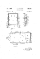
- FIG. 1 is a side view of the trailer constructed in accordance with the teaching of this invention, part of the trailer being shown in section, said trailer being shown contracted.
- FIG. 2 is a side view of said trailer showing the same expanded, a part of the movable section being shown in section.
- FIG. 3 is a vertical cross-section of the trailer along the line 3-3 of FIG. 1.
- FIG. 4 is a vertical section of the right upper corner of the trailer, as shown in FIG. 3, showing the construction of the double side wall and the arrangement of the various parts of the movable section therein.
- FIG. 5 is a horizontal section of the expanded trailer taken along the line 5-5 of FIG. 2, a part of it being shown in section.
- FIG. 6 is a vertical cross-section of the movable section taken along the line 6--6 of FIG. 2.
- FIG. 7 is a vertical section of the left lower corner of the trailer as shown in FIG. 6.
- FIG. 8 is a vertical longitudinal section of said trailer taken along the line 88 of FIG. 6, showing the trailer expanded but with the roof, floor and bed bunks in folded position, and
- FIG. 9 is a vertical cross-section of the back side and floor of the contracted trailer.
- the trailer comprising the subject matter of this invention comprises a main unit 1 and a movable section 20.
- the main section consists of a front wall 2, double walled sides 3, roof 4, and a floor 5 and closed by a back wall -6 of the movable section 20.
- the trailer is supported in a usual manner by a pair of wheels 7.
- the trailer is towed by a draw bar 10 secured to the main unit 1.
- a removable jack 11 may be The side walls of the movable 2,995,398 Patented Aug. 8, 1961 provided under the draw bar 10 for supporting the front end of said trailer while the same is parked.
- the double walled sides 3 are formed by outer sides 12 and partitions 15 arranged parallel to said outer sides and in spaced relation thereto to form long and narrow passages 17 therebetween.
- the partitions 15 extend from the floor 5 to the roof 4 and almost the entire length of the trailer, terminating only the thickness of the back wall 6 away from the very end of the trailer.
- the movable section 20 of the trailer consists of side walls 21 which are slidably arranged in the passages 17 near the outer sides 12.
- the side walls 21 may be made of any suitable material, such as plywood, or aluminum alloy and may be supported, or reinforced, by a suitable frame.
- said side walls have an inverted U-shaped channel 22 and a U-shaped channel 23 riveted or otherwise secured to the top and to the bottom thereof respectively.
- the upper channel 22 has attached thereto a hinge 25 extending outwardly from said side wall a'certain distance, to which hinge one half of the roof 27 is swingably secured, as shown in detail in FIG. 4.
- the half of the roof 27 is normally folded downwardly parallel and in spaced relation to said side wall 21.
- a bunk 28 which is hinged at 30 to approximately the middle of said side wall.
- the channel 22 and the hinge 25 carry a roller 32 supported by ears 33 extending upwardly from the top of said channel and binge.
- the roller 32 abuts a slide 35 secured to the side wall 12 directly and by supports 36 and extends the length of the passage 17.
- the roller 32 abutting the slide 35 keeps the side wall 21 level while the movable section is pulled out or pushed in.
- the outward movement of the movable section is stopped by a stop 37 secured to the underside of the slide 35 near the rear end of the trailer.
- the roller 32 contacts said stop 37 when the movable section is pulled out of the main unit to its outermost position.
- the U-shaped bottom channel 23 is riveted, or otherwise secured, to the lower edge of the side wall 21, and has a hinge 40 secured to or integral with said channel.
- the hinge 40 extends some distance away from the channel 23 and carries swingably secured thereto a half of the floor 41. When folded the floor half extends upwardly and parallel to and some distance away from said wall.
- a bunk 28' is swingably secured between said side Wall and said floor half by a hinge 45 secured to the bottom channel 23 above the hinge 40 and in close proximity thereto.
- the lower edge of the side wall 21 rides on a roller 48 while the movable section is pulled out, or pushed in.
- the roller 48 is rotatably arranged in the rear end of a channel 49 extending under the side 3.
- the rear end of the channel 49 is depressed slightly in relation to the floor 5, as shown in FIG. 7, so that the top of the roller 48 is substantially level with said floor.
- the roof half 27 is provided with a shield 51 in form of a long narrow strip, preferably of metal, or plastic, which is secured to the roof part of the hinge 25 When the movable section is within the main unit 1, the shield 51 extends upwardly, as shown in FIG. 4. When the movable section is pulled out of the main unit, and the roof is properly arranged over the movable section, the shields 51 cover the hinges 25 and thus prevent rain from seeping into the section.
- One of the roof halves 27 is provided with a central protecting strip 53 which is secured to the outer end of said half.
- the strip 53 covers the joint of two halves 27, and thus helps to keep the movable section dry.
- the movable unit is securely connected to the unit by a pair of bolts 56 secured to the cross walls of the channels 49, which bolts pass through respective holes in a cross angle iron 57, supporting the back wall 6, and resting on the rear end of the floor of the main unit.
- the bolts 56 are secured therein by nuts 58.
- locking devices may also be provided on the sides 3 and the back wall 6 to securely hold them to-' gether, as shown at 59.
- The'back wall 6 is provided with two retractable caster wheels 60 carried by said wall in close' proximity to its ends. Each wheel 60 is secured to the end of a threaded bar 61 screwed into a pipe 62. The latter is slidably arranged in a silde 63 fastened to the back wall 6 V The wheels 60 normally are retracted and held in retracted position by a locking bolt 65 passing through an upper hole 66 provided in the slide and through a hole in the pipe 62.
- the bolt 65- is taken out of the upper hole 66, whereupon thewhe'el 60 with the bar 61 and the pipe 62 drop down to the ground and the bolt 65'is placed through a lower hole 67, and through said hole in the pipe 62. If necessary, an adjustment may be made by rotating the wheel 60 with its bar 61 in relation to the pipe 62 so that the 501! 65' is easily passed through said holes while the wheel 60 rests on the ground.
- the movable section 20 is pulled out of the main unit 1.
- the rear end of said section rides on the wheels 60 while its side walls 21 slide on the rollers 48 until the upper rollers 32 strike the stops 37.
- the length of the bars 61 is adjusted to place the movable section" in substantially horizontal position.
- the floor halves are let down.
- the front end of the floor havles -41 rests on the rear end of the main unit while the rear end rests on the angle iron 57.
- the free ends of said halves are made to overlap each other as shown at 59.
- the roof halves 27 are raised and the night half, viewing FIG. 6, is lowered under the strip 3.
- the ends of the roof halves 27 are cut at an angle directed downwardly and to the right, viewing FIG. 6, so that the end of the right half is jammed between the bevelled end of the left half and the strip 54, thus securely holding the roof in place. 7
- a swingable hook 70 may be provided on the ceiling of the main unit near the rear end thereof,
- Two or more removable bolts 68 may be provided in" the back wall 6 to support the rear end of the roof, as shown in FIG. 2.
- a flexible plastic strip 72 is placed at the junction of said roofand wall, as shown in FIG. 2. Then the upper bunks 28 are lowered with their outer sides supported by straps 7-1, and the lower bunks 28' are lowered on supports 72, which may be foldably carried in said bunks.
- a trailer having a front wall, a floor, a roof and double walls on the sides forming the main unit, wheels for supporting the same, a movable unit consistingof a back wall normally closing the main unit, side walls' secured to said back wall, a floor divided into two separate halves each half being hinged to the bottom of the adjoining side wall and foldable against the same, a roof divided into two separate halves, each half being hinged to the top of the adjoining side wall and foldable against the same, said side walls with the halves of said floor and roof folded thereagainst being slid into said double walls for contracting said trailer, said floor and roof halves forming the floor and the roof of the movable section when the trailer is expanded by moving said movable section out of the main unit, means for supporting said main unit, and means for supporting the movable section when the trailer is expanded.
- An expandable trailer comprising a main unit and a movable" section adapted to move in and out of said main unit, the main unit including a floor, two parallelside wane on said floor, a front wall extending from one side wall to the other, and a roof extending from one side wan to the other and from the front wall to the back ends of said side walls, said movable section including two side walls' slidable in the main unit, a back wall secured to the back ends of said side walls of said movable seclion for closing the main unit when the movable section is within the main unit, a floor consisting of two separate halves, each half being hinged to the bottom of the adjoining side wall of the movable section, and a roof consisting of two separate halves, each half being hinged to the top of the adjoining side wall of the movable section, said floor halves and roof halves being folded against the inner sides of said adjoining side walls when the movable section is inside of the main unit, and forming. the floor and the roof of
Description
Aug. 8, 1961 J. R DAVENPORT EXPANDABLE TRAILER 3 Sheets-Sheet 1 Filed Nov. 19, 1959 INVENTOR.
JAM/55 E. DAVENPORT BY fleuuzwwlu/ A TTOENEY 3 SheetsSheet. 2
J. R DAVENPORT EXPANDABLE TRAILER Aug. 8, 1961 Filed Nov. 19, 1959 IN VEN TOR. JA MES 1?. DA l/ENPOJET BY fiz zexmow ATTORNEY 1961' J. R. DAVENPORT 2,995,398
EXPANDABLE TRAILER Filed Nov. 19, 1959 5 Sheets-Sheet. 3
INVENTOR.
JAME5 R DAVENPORT BY fleuwm/fld fi A TTO/ZNEY United States Patent "ice 2,995,398 EXPANDABLE TRAILER James R. Davenport, 1364 Goetinger St., San Francisco, Calif.
Filed Nov. 19, 1959, Ser. No. 854,190 6 Claims. (Cl. 296-26) Another object of the invention is to provide an ex-- pandable trailer consisting of a main unit, having double walled sides, and of a movable section having a back wall and side walls secured thereto and movable within said double walls so that said back wall, which normally closes the main unit, with said side walls, may be pulled out of the main unit. section each carry a half of the roof and a half of the floor folded thereon, which halves are thereupon unfolded to form the roof and the floor respectively.
Other objects and advantages will appear as the specification proceeds and the novel features of the device will be particularly pointed out in the claims hereto annexed.
In this specification and the annexed drawing, the invention is illustrated in the form considcredto be'the best but it is understood that the invention is not limited to such form; and it is also to be understood that in and by the claims following the description, it is desired to cover the invention in whatsoever form it may be embodied.
This invention is illustrated in the accompanying drawings forming a part of this invention, in which:
FIG. 1 is a side view of the trailer constructed in accordance with the teaching of this invention, part of the trailer being shown in section, said trailer being shown contracted.
FIG. 2 is a side view of said trailer showing the same expanded, a part of the movable section being shown in section.
FIG. 3 is a vertical cross-section of the trailer along the line 3-3 of FIG. 1.
FIG. 4 is a vertical section of the right upper corner of the trailer, as shown in FIG. 3, showing the construction of the double side wall and the arrangement of the various parts of the movable section therein.
FIG. 5 is a horizontal section of the expanded trailer taken along the line 5-5 of FIG. 2, a part of it being shown in section.
FIG. 6 is a vertical cross-section of the movable section taken along the line 6--6 of FIG. 2.
FIG. 7 is a vertical section of the left lower corner of the trailer as shown in FIG. 6.
FIG. 8 is a vertical longitudinal section of said trailer taken along the line 88 of FIG. 6, showing the trailer expanded but with the roof, floor and bed bunks in folded position, and
FIG. 9 is a vertical cross-section of the back side and floor of the contracted trailer.
The trailer comprising the subject matter of this invention comprises a main unit 1 and a movable section 20. The main section consists of a front wall 2, double walled sides 3, roof 4, and a floor 5 and closed by a back wall -6 of the movable section 20. The trailer is supported in a usual manner by a pair of wheels 7. The trailer is towed by a draw bar 10 secured to the main unit 1. If desired, a removable jack 11 may be The side walls of the movable 2,995,398 Patented Aug. 8, 1961 provided under the draw bar 10 for supporting the front end of said trailer while the same is parked.
The double walled sides 3 are formed by outer sides 12 and partitions 15 arranged parallel to said outer sides and in spaced relation thereto to form long and narrow passages 17 therebetween. The partitions 15 extend from the floor 5 to the roof 4 and almost the entire length of the trailer, terminating only the thickness of the back wall 6 away from the very end of the trailer.
The movable section 20 of the trailer consists of side walls 21 which are slidably arranged in the passages 17 near the outer sides 12. The side walls 21 may be made of any suitable material, such as plywood, or aluminum alloy and may be supported, or reinforced, by a suitable frame. Preferably, said side walls have an inverted U-shaped channel 22 and a U-shaped channel 23 riveted or otherwise secured to the top and to the bottom thereof respectively. The upper channel 22 has attached thereto a hinge 25 extending outwardly from said side wall a'certain distance, to which hinge one half of the roof 27 is swingably secured, as shown in detail in FIG. 4. The half of the roof 27 is normally folded downwardly parallel and in spaced relation to said side wall 21. Between said side wall 21 and the half of the roof 27 is folded upwardly a bunk 28, which is hinged at 30 to approximately the middle of said side wall. At the front end of said side wall 21 the channel 22 and the hinge 25 carry a roller 32 supported by ears 33 extending upwardly from the top of said channel and binge. The roller 32 abuts a slide 35 secured to the side wall 12 directly and by supports 36 and extends the length of the passage 17. The roller 32 abutting the slide 35 keeps the side wall 21 level while the movable section is pulled out or pushed in. The outward movement of the movable section is stopped by a stop 37 secured to the underside of the slide 35 near the rear end of the trailer. The roller 32 contacts said stop 37 when the movable section is pulled out of the main unit to its outermost position.
The U-shaped bottom channel 23 is riveted, or otherwise secured, to the lower edge of the side wall 21, and has a hinge 40 secured to or integral with said channel. The hinge 40 extends some distance away from the channel 23 and carries swingably secured thereto a half of the floor 41. When folded the floor half extends upwardly and parallel to and some distance away from said wall. A bunk 28' is swingably secured between said side Wall and said floor half by a hinge 45 secured to the bottom channel 23 above the hinge 40 and in close proximity thereto.
The lower edge of the side wall 21 rides on a roller 48 while the movable section is pulled out, or pushed in. The roller 48 is rotatably arranged in the rear end of a channel 49 extending under the side 3. The rear end of the channel 49 is depressed slightly in relation to the floor 5, as shown in FIG. 7, so that the top of the roller 48 is substantially level with said floor.
In order to prevent the hinge 25' from leaking during rain the roof half 27 is provided with a shield 51 in form of a long narrow strip, preferably of metal, or plastic, which is secured to the roof part of the hinge 25 When the movable section is within the main unit 1, the shield 51 extends upwardly, as shown in FIG. 4. When the movable section is pulled out of the main unit, and the roof is properly arranged over the movable section, the shields 51 cover the hinges 25 and thus prevent rain from seeping into the section.
One of the roof halves 27 is provided with a central protecting strip 53 which is secured to the outer end of said half. When the roof is raised and properly arranged over the movable section, the strip 53 covers the joint of two halves 27, and thus helps to keep the movable section dry.
The movable unit is securely connected to the unit by a pair of bolts 56 secured to the cross walls of the channels 49, which bolts pass through respective holes in a cross angle iron 57, supporting the back wall 6, and resting on the rear end of the floor of the main unit. The bolts 56 are secured therein by nuts 58. If desired, locking devices may also be provided on the sides 3 and the back wall 6 to securely hold them to-' gether, as shown at 59.
The'back wall 6 is provided with two retractable caster wheels 60 carried by said wall in close' proximity to its ends. Each wheel 60 is secured to the end of a threaded bar 61 screwed into a pipe 62. The latter is slidably arranged in a silde 63 fastened to the back wall 6 V The wheels 60 normally are retracted and held in retracted position by a locking bolt 65 passing through an upper hole 66 provided in the slide and through a hole in the pipe 62. I
When it is desired to extend the trailer, the bolt 65- is taken out of the upper hole 66, whereupon thewhe'el 60 with the bar 61 and the pipe 62 drop down to the ground and the bolt 65'is placed through a lower hole 67, and through said hole in the pipe 62. If necessary, an adjustment may be made by rotating the wheel 60 with its bar 61 in relation to the pipe 62 so that the 501! 65' is easily passed through said holes while the wheel 60 rests on the ground.
Thereupon the movable section 20 is pulled out of the main unit 1. The rear end of said section rides on the wheels 60 while its side walls 21 slide on the rollers 48 until the upper rollers 32 strike the stops 37. Then the length of the bars 61 is adjusted to place the movable section" in substantially horizontal position.
Then the floor halves are let down. The front end of the floor havles -41 rests on the rear end of the main unit while the rear end rests on the angle iron 57. The free ends of said halves are made to overlap each other as shown at 59. The roof halves 27 are raised and the night half, viewing FIG. 6, is lowered under the strip 3. The ends of the roof halves 27 are cut at an angle directed downwardly and to the right, viewing FIG. 6, so that the end of the right half is jammed between the bevelled end of the left half and the strip 54, thus securely holding the roof in place. 7
If desired, a swingable hook 70 may be provided on the ceiling of the main unit near the rear end thereof,
so that the front end of the roof may be placed thereon.
Two or more removable bolts 68 may be provided in" the back wall 6 to support the rear end of the roof, as shown in FIG. 2. In order to prevent rain from leaking between said roof and the back wall a flexible plastic strip 72 is placed at the junction of said roofand wall, as shown in FIG. 2. Then the upper bunks 28 are lowered with their outer sides supported by straps 7-1, and the lower bunks 28' are lowered on supports 72, which may be foldably carried in said bunks.
I claim:
1. A trailer having a front wall, a floor, a roof and double walls on the sides forming the main unit, wheels for supporting the same, a movable unit consistingof a back wall normally closing the main unit, side walls' secured to said back wall, a floor divided into two separate halves each half being hinged to the bottom of the adjoining side wall and foldable against the same, a roof divided into two separate halves, each half being hinged to the top of the adjoining side wall and foldable against the same, said side walls with the halves of said floor and roof folded thereagainst being slid into said double walls for contracting said trailer, said floor and roof halves forming the floor and the roof of the movable section when the trailer is expanded by moving said movable section out of the main unit, means for supporting said main unit, and means for supporting the movable section when the trailer is expanded.
2. A trailer as described in claim 1 and having means for stopping the outward movement of the movable section when the trailer is expanded to its maximum.
3. A trailer as described in claim 1, and having a roller in the main unit arranged under each side wall of the movable section for reducing friction between said walls and the main unit when the movable section is pulledout of the latter.
4. A trailer as described in claim 1, and having bunks hinged to the sidewalls of the movable section, said bunks being folded against said side walls between the sarne andthe floor and roof halves, when the trailer is contracted.
5. A trailer as described in claim 1, and having a roller secured, to the top of the front end of the side walls of the movable section, said main unit having a slide within each double wall against which the last mentioned roller rides when the movable section is pulled out or pushed in the main unit.
6. An expandable trailer comprising a main unit and a movable" section adapted to move in and out of said main unit, the main unit including a floor, two parallelside wane on said floor, a front wall extending from one side wall to the other, and a roof extending from one side wan to the other and from the front wall to the back ends of said side walls, said movable section including two side walls' slidable in the main unit, a back wall secured to the back ends of said side walls of said movable seclion for closing the main unit when the movable section is within the main unit, a floor consisting of two separate halves, each half being hinged to the bottom of the adjoining side wall of the movable section, and a roof consisting of two separate halves, each half being hinged to the top of the adjoining side wall of the movable section, said floor halves and roof halves being folded against the inner sides of said adjoining side walls when the movable section is inside of the main unit, and forming. the floor and the roof of said movable section whenthe latter is pulled out to expand the trailer; and, a means for supporting said main unit, and a means for supporting the movable section when the trailer is expanded.
References Cited in the file of this patent UNITED STATES PATENTS 2,177,394 Pierce Oct. 24, 1939 2,898,144 Ferrera Aug. 4, 1959 2,901,282 Meaker Aug. 25, 1959' FOREIGN PATENTS 53,167 Austria Aug; 13, 1890'
Priority Applications (1)
| Application Number | Priority Date | Filing Date | Title |
|---|---|---|---|
| US854190A US2995398A (en) | 1959-11-19 | 1959-11-19 | Expandable trailer |
Applications Claiming Priority (1)
| Application Number | Priority Date | Filing Date | Title |
|---|---|---|---|
| US854190A US2995398A (en) | 1959-11-19 | 1959-11-19 | Expandable trailer |
Publications (1)
| Publication Number | Publication Date |
|---|---|
| US2995398A true US2995398A (en) | 1961-08-08 |
Family
ID=25317979
Family Applications (1)
| Application Number | Title | Priority Date | Filing Date |
|---|---|---|---|
| US854190A Expired - Lifetime US2995398A (en) | 1959-11-19 | 1959-11-19 | Expandable trailer |
Country Status (1)
| Country | Link |
|---|---|
| US (1) | US2995398A (en) |
Cited By (16)
| Publication number | Priority date | Publication date | Assignee | Title |
|---|---|---|---|---|
| US3078117A (en) * | 1961-02-27 | 1963-02-19 | Arthur H Martini | Camping and touring trailer |
| US3722947A (en) * | 1971-11-29 | 1973-03-27 | M Zucca | Retractable side frame for flat bed trailer |
| US4397497A (en) * | 1980-10-02 | 1983-08-09 | Alonzo Jr George J | Expandable camper body |
| US4861049A (en) * | 1983-10-28 | 1989-08-29 | Chemical New York Corporation | Mobile bank teller unit |
| US5050927A (en) * | 1990-09-04 | 1991-09-24 | Verne Montanari | Expansible motor home |
| US5090335A (en) * | 1988-08-23 | 1992-02-25 | Russell Kenneth R | Table for truck bed |
| US5127697A (en) * | 1990-04-12 | 1992-07-07 | St Marie Normand | Inconspicuous expandable van |
| US5628541A (en) * | 1995-01-19 | 1997-05-13 | R-N-R International, Inc. | Expandable coach having at least one expansion chamber |
| US5639139A (en) * | 1996-06-11 | 1997-06-17 | Rush; L. C. | Telescoping trailer |
| US5971459A (en) * | 1997-08-29 | 1999-10-26 | Gauthier; Gaston | Camper extension |
| US6561570B2 (en) * | 2000-12-29 | 2003-05-13 | Fleetwood Folding Trailers, Inc. | Expandable travel trailer |
| US6976721B2 (en) | 2003-03-05 | 2005-12-20 | Happijac Company | Slide-out mechanisms and systems |
| US6981728B2 (en) | 1999-11-23 | 2006-01-03 | Happijac Company | Sliding mechanisms and systems |
| US7052064B2 (en) | 1999-11-23 | 2006-05-30 | Happijac Company | Sliding mechanisms and systems |
| US7712820B1 (en) | 2008-02-29 | 2010-05-11 | Gordon Kyle | Easy open collapsible trailer |
| US9007012B2 (en) | 2009-01-21 | 2015-04-14 | Lippert Components Manufacturing, Inc. | Retractable room actuation assembly for recreational vehicle |
Citations (4)
| Publication number | Priority date | Publication date | Assignee | Title |
|---|---|---|---|---|
| AT53167B (en) * | 1908-10-24 | 1912-04-25 | Gustave Weissmann | Lighting fixtures for electrical effect and advertising lighting. |
| US2177394A (en) * | 1937-11-16 | 1939-10-24 | Arthur J Drilling | Extensible vehicle body |
| US2898144A (en) * | 1957-07-22 | 1959-08-04 | Ferrera John | Floor supporting means for expansible trailers |
| US2901282A (en) * | 1957-01-15 | 1959-08-25 | Stanley B Meaker | Trailer construction |
-
1959
- 1959-11-19 US US854190A patent/US2995398A/en not_active Expired - Lifetime
Patent Citations (4)
| Publication number | Priority date | Publication date | Assignee | Title |
|---|---|---|---|---|
| AT53167B (en) * | 1908-10-24 | 1912-04-25 | Gustave Weissmann | Lighting fixtures for electrical effect and advertising lighting. |
| US2177394A (en) * | 1937-11-16 | 1939-10-24 | Arthur J Drilling | Extensible vehicle body |
| US2901282A (en) * | 1957-01-15 | 1959-08-25 | Stanley B Meaker | Trailer construction |
| US2898144A (en) * | 1957-07-22 | 1959-08-04 | Ferrera John | Floor supporting means for expansible trailers |
Cited By (25)
| Publication number | Priority date | Publication date | Assignee | Title |
|---|---|---|---|---|
| US3078117A (en) * | 1961-02-27 | 1963-02-19 | Arthur H Martini | Camping and touring trailer |
| US3722947A (en) * | 1971-11-29 | 1973-03-27 | M Zucca | Retractable side frame for flat bed trailer |
| US4397497A (en) * | 1980-10-02 | 1983-08-09 | Alonzo Jr George J | Expandable camper body |
| US4861049A (en) * | 1983-10-28 | 1989-08-29 | Chemical New York Corporation | Mobile bank teller unit |
| US5090335A (en) * | 1988-08-23 | 1992-02-25 | Russell Kenneth R | Table for truck bed |
| US5127697A (en) * | 1990-04-12 | 1992-07-07 | St Marie Normand | Inconspicuous expandable van |
| US5050927A (en) * | 1990-09-04 | 1991-09-24 | Verne Montanari | Expansible motor home |
| US5628541A (en) * | 1995-01-19 | 1997-05-13 | R-N-R International, Inc. | Expandable coach having at least one expansion chamber |
| US5639139A (en) * | 1996-06-11 | 1997-06-17 | Rush; L. C. | Telescoping trailer |
| US5971459A (en) * | 1997-08-29 | 1999-10-26 | Gauthier; Gaston | Camper extension |
| US7234747B2 (en) | 1999-11-23 | 2007-06-26 | Lippert Components, Inc. | Sliding mechanisms and systems |
| US6981728B2 (en) | 1999-11-23 | 2006-01-03 | Happijac Company | Sliding mechanisms and systems |
| US7052064B2 (en) | 1999-11-23 | 2006-05-30 | Happijac Company | Sliding mechanisms and systems |
| US7052065B2 (en) | 1999-11-23 | 2006-05-30 | Happijac Company | Sliding mechanisms and systems |
| US6561570B2 (en) * | 2000-12-29 | 2003-05-13 | Fleetwood Folding Trailers, Inc. | Expandable travel trailer |
| US6854787B2 (en) * | 2000-12-29 | 2005-02-15 | Fleetwood Folding Trailers, Inc. | Expandable travel trailer |
| US6976721B2 (en) | 2003-03-05 | 2005-12-20 | Happijac Company | Slide-out mechanisms and systems |
| US7150483B2 (en) | 2003-03-05 | 2006-12-19 | Recreation Systems Inc. | Flush floor slide-out mechanisms and systems |
| US7712820B1 (en) | 2008-02-29 | 2010-05-11 | Gordon Kyle | Easy open collapsible trailer |
| US9007012B2 (en) | 2009-01-21 | 2015-04-14 | Lippert Components Manufacturing, Inc. | Retractable room actuation assembly for recreational vehicle |
| US9193291B2 (en) | 2009-01-21 | 2015-11-24 | Lippert Components Manufacturing, Inc. | Retractable room actuation assembly for recreational vehicle |
| US9694733B2 (en) | 2009-01-21 | 2017-07-04 | Lippert Components Manufacturing, Inc. | Retractable room actuation assembly for recreational vehicle |
| US10093219B2 (en) | 2009-01-21 | 2018-10-09 | Lippert Components Manufacturing, Inc. | Retractable room actuation assembly for recreational vehicle |
| US10471878B2 (en) | 2009-01-21 | 2019-11-12 | Lippert Components Manufacturing, Inc. | Retractable room actuation assembly for recreational vehicle |
| US11059413B2 (en) | 2009-01-21 | 2021-07-13 | Lippert Components Manufacturing, Inc. | Retractable room actuation assembly for recreational vehicle |
Similar Documents
| Publication | Publication Date | Title |
|---|---|---|
| US2995398A (en) | Expandable trailer | |
| US3466082A (en) | Pickup truck bed mounted camper tent | |
| US2490014A (en) | Trailer for motor vehicles | |
| US3711882A (en) | Elevated doorway retractable ramp structure | |
| US3572809A (en) | Expansible mobile home and fittings therefore | |
| US2193352A (en) | Trailer | |
| US4192544A (en) | Telescoping extension for vehicles | |
| US3583755A (en) | Camping trailer | |
| US11312288B2 (en) | Trailer and housing system | |
| US2837778A (en) | Folding trailers | |
| US3185518A (en) | Automotive camping device for use with station wagons | |
| US2481230A (en) | Vehicle trailer | |
| US3623762A (en) | Penthouse car camper | |
| US3429608A (en) | Knockdown trailer unit | |
| US2530578A (en) | Body for plumbers' trucks | |
| US3608953A (en) | Collapsible camping trailer | |
| US4199186A (en) | Portable stock rack for pickup truck | |
| US3375959A (en) | Convertible and detachable luggage rack for station wagons | |
| US2182967A (en) | Collapsible auto trailer | |
| US3097013A (en) | Collapsible portable cabin structure for automotive vehicles | |
| US3463540A (en) | Expandable camper | |
| US2719054A (en) | Trailer end gate construction | |
| US3677600A (en) | Camper trailer | |
| US3001813A (en) | Vehicular camping trailers | |
| US2856645A (en) | Trailer house |