US3120877A - Exhaust noise suppressor for reaction engines - Google Patents
Exhaust noise suppressor for reaction engines Download PDFInfo
- Publication number
- US3120877A US3120877A US65389A US6538960A US3120877A US 3120877 A US3120877 A US 3120877A US 65389 A US65389 A US 65389A US 6538960 A US6538960 A US 6538960A US 3120877 A US3120877 A US 3120877A
- Authority
- US
- United States
- Prior art keywords
- rungs
- exhaust
- ranks
- rank
- screen
- Prior art date
- Legal status (The legal status is an assumption and is not a legal conclusion. Google has not performed a legal analysis and makes no representation as to the accuracy of the status listed.)
- Expired - Lifetime
Links
- 238000006243 chemical reaction Methods 0.000 title claims description 21
- 238000011144 upstream manufacturing Methods 0.000 description 22
- 238000001816 cooling Methods 0.000 description 15
- XLYOFNOQVPJJNP-UHFFFAOYSA-N water Substances O XLYOFNOQVPJJNP-UHFFFAOYSA-N 0.000 description 12
- 239000000463 material Substances 0.000 description 10
- 230000009467 reduction Effects 0.000 description 8
- 239000003570 air Substances 0.000 description 7
- 239000002184 metal Substances 0.000 description 7
- 238000012856 packing Methods 0.000 description 7
- 238000009792 diffusion process Methods 0.000 description 6
- 239000010935 stainless steel Substances 0.000 description 5
- 229910001220 stainless steel Inorganic materials 0.000 description 5
- 238000013519 translation Methods 0.000 description 5
- 229910001209 Low-carbon steel Inorganic materials 0.000 description 4
- 239000007921 spray Substances 0.000 description 4
- 230000007704 transition Effects 0.000 description 4
- 241000239290 Araneae Species 0.000 description 3
- 230000007797 corrosion Effects 0.000 description 3
- 238000005260 corrosion Methods 0.000 description 3
- 238000013461 design Methods 0.000 description 3
- 238000010008 shearing Methods 0.000 description 3
- 230000035939 shock Effects 0.000 description 3
- 238000003466 welding Methods 0.000 description 3
- 230000009471 action Effects 0.000 description 2
- 230000008901 benefit Effects 0.000 description 2
- 239000003795 chemical substances by application Substances 0.000 description 2
- 238000010276 construction Methods 0.000 description 2
- 239000000498 cooling water Substances 0.000 description 2
- 230000003028 elevating effect Effects 0.000 description 2
- 239000007789 gas Substances 0.000 description 2
- 238000000034 method Methods 0.000 description 2
- 238000012986 modification Methods 0.000 description 2
- 230000004048 modification Effects 0.000 description 2
- 230000000644 propagated effect Effects 0.000 description 2
- 239000007787 solid Substances 0.000 description 2
- 229910000975 Carbon steel Inorganic materials 0.000 description 1
- 241000582342 Carria Species 0.000 description 1
- 238000010521 absorption reaction Methods 0.000 description 1
- 239000012080 ambient air Substances 0.000 description 1
- 238000013459 approach Methods 0.000 description 1
- 239000010425 asbestos Substances 0.000 description 1
- 230000004888 barrier function Effects 0.000 description 1
- 238000003287 bathing Methods 0.000 description 1
- 239000010962 carbon steel Substances 0.000 description 1
- AQIXAKUUQRKLND-UHFFFAOYSA-N cimetidine Chemical compound N#C/N=C(/NC)NCCSCC=1N=CNC=1C AQIXAKUUQRKLND-UHFFFAOYSA-N 0.000 description 1
- 150000001875 compounds Chemical class 0.000 description 1
- 239000002826 coolant Substances 0.000 description 1
- 230000003292 diminished effect Effects 0.000 description 1
- 238000007599 discharging Methods 0.000 description 1
- 239000000835 fiber Substances 0.000 description 1
- 239000003365 glass fiber Substances 0.000 description 1
- 230000001939 inductive effect Effects 0.000 description 1
- 210000004072 lung Anatomy 0.000 description 1
- 238000004519 manufacturing process Methods 0.000 description 1
- 230000007246 mechanism Effects 0.000 description 1
- 230000002093 peripheral effect Effects 0.000 description 1
- 238000002407 reforming Methods 0.000 description 1
- 229910052895 riebeckite Inorganic materials 0.000 description 1
- 238000012360 testing method Methods 0.000 description 1
- 230000008016 vaporization Effects 0.000 description 1
- 238000009834 vaporization Methods 0.000 description 1
Images


Classifications
-
- B—PERFORMING OPERATIONS; TRANSPORTING
- B64—AIRCRAFT; AVIATION; COSMONAUTICS
- B64F—GROUND OR AIRCRAFT-CARRIER-DECK INSTALLATIONS SPECIALLY ADAPTED FOR USE IN CONNECTION WITH AIRCRAFT; DESIGNING, MANUFACTURING, ASSEMBLING, CLEANING, MAINTAINING OR REPAIRING AIRCRAFT, NOT OTHERWISE PROVIDED FOR; HANDLING, TRANSPORTING, TESTING OR INSPECTING AIRCRAFT COMPONENTS, NOT OTHERWISE PROVIDED FOR
- B64F1/00—Ground or aircraft-carrier-deck installations
- B64F1/26—Ground or aircraft-carrier-deck installations for reducing engine or jet noise; Protecting airports from jet erosion
Definitions
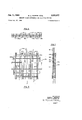
- EXHAUST NoIsE SUPPRESSOR FOR REACTION ENGINES Filed Oct. 27, 1960 4 Sheets-Sheet 3- INVENTORS.
- the noise is primarily due to the tearing or shearing action of the exhaust stream against the ambient air. It has been known to the prior art that if such a shearing action could be diffused or broken up a reduction in noise .would result, and various attempts have been made.
- the self-noise of any such screen is related directly to the velocity of the turbulences created by the grid in the exhaust. If the density of the grid, that is, the amount of grid material interposed in the exhaust, is adequate to provide reasonably effective diffusion of the exhaust it will not allow a sufficient portion of the stream to get through, and back-pressures the motor. If not that dense, there is a tendency for the exhaust stream to reform downstream from the grid.
- a still further object is to provide a suppressor system having an improved exhaust diffusing screen.
- Another object of this invention is to provide an exhaust suppressor wherein the diffused exhaust stream is prevented from reforming.
- An additional object is the provision of a suppressor system wherein the motor is not backapressured.
- a still further object is to provide a suppressor system suitable for use in an exhaust stream during conditions 3,lZ,87? Patented Feb. '51, 1964 of extreme heat such as afterb'urner operation or rocket exhaust.
- FIGURE 1 is a semi-schematic perspective view of the suppressor and its carriage, partially broken away;
- FiGURE 2 is a diagrammatic representation of the general reflection pattern of self-noise from a grid of the prior art
- FIGURE 3 is an elevation in centerl-ine section of the present noise suppressor in operating position with a reaction engine
- FIGURE 4 is a perspective view of one embodiment of the improved three-dimensional cnibwork diffuser screen, with a schematic representation of the Water cooling system thereof;
- FIGURE 5 is a front elevation of another embodiment of the improved three-dimensional cribwork diffuser screen
- FIGURE 6 is a plan view of the screen of FIGURE 5.
- FIGURE 7 is a side elevation of the screen of FIG- URE 5.
- the suppressor 11 on its wheeled carriage 5.
- the suppressor has Ia generally cylindrical exhaust entrance section 12 open at the outer end for reception of the exhaust nozzle of the engine, and communicating coaxially at the inner end with a larger generally cylindrical expansion chamber 13, which in turn communicates with a generally cylindrical vertical discharge stack 14.
- Carria e 5 is provided for moving the suppressor into operating position with an engine, and has stanchions 6 supporting the suppressor.
- the height of the suppressor is controlled by elevating cylinders 7 or other convenient means, in order that it may be opposed to an engine installed on an aircraft, and the elevations of the ends are separately controllable to render it coaxial with an engine which may not be precisely horizontal.
- the device will be operated in an approximately horizontal position, and all references to horizontal position are intended to be approximate.
- An improved diffuser screen 16 is positioned at the inner end of the entrance section transversely to the horizontal axis thereof and across the aperture communicating with the expansion chamber.
- An internal resistance grid 1'7 of different design from the diffusing screen, is positioned within the expansion chamber on the axis thereof and transverse to such axis. The resistance grid is provided with means for axial translation so that its distance firom the diffusing screen may be altered.
- the stack 14 is of the same diameter, in this embodiment, as the expansion chamber, both these elements being double-walled and having sound-absorbing acoustical material 1% disposed between the walls.
- a resonant chamber surrounds the upper portion of the stack and communicates with the interior thereof.
- PlGURE 2 there is shown in diagrammatic fashion the self-noise reflection pattern obtained from placing a simple crisscross grid, as in the prior art, in the exhaust stream of a reaction engine.
- Such an engine 21 is shown in outline discharging exhaust 22 agt inst a crisscross grid 23.
- Strong shock waves are set up ahead of the elements of the Pdthough the main reflection is of generally conical pattern expanding in the upstream direction and somewhat occluded at the center of the cone by the engine, as shown, there is some reflection throughout the entire upstream hemisphere.
- the cone of reflected noise is shown for the purpose of graphic representation as having its point of origin at the center of the grid, but it will be understood that self-noise originates at all portions of the grid upon which the exhaust stream impinges.
- a region of turbulence of the exhaust occurs directly downstream from the grid as shown, but further downstream the gases have a tendency to reform into a jet stream. Placing the grid within a tube or chamber, shown in dotted lines at does not materially alter the reflection pattern nor the reformation of the jet stream.
- the present invention overcomes the foregoing dis advantage of the prior art by two means, staged diffusion and control of diffuser noise beamed into the forward field.
- staged diffusion there is provided a diffuser screen comprising a labyrinthine cribwork structure having considerable extension in the axial direction.
- This screen is hereinafter referred to as threedimensional, to distinguish it from the simple grids of the prior art which were substantially plane.
- staged difusion causes the jet stream to undergo pressure and velocity reduction in increments, thus reducing the strength of any one shock phase.
- Control of noise beamed upstream is accomplished by acoustical bathing and by inducing a flow of aspirated air at sonic velocity into the suppressor entrance, against which flow the diffuser noise cannot be propagated up stream.
- FIGURE 3 shows a sectional elevation of the complete suppressor combination (carriage and elevating mechanism not shown) with the jet nozzle of a reaction engine opposed to the suppressor in operating position.
- the suppressor 11 comprises a generally cylindrical entrance section 12 coaxial with a generally cylindrical expansion section 13 of larger diameter, and a vertical stack 14 communicating with the expansion chamber, the stack being surrounded by a resonant chamber 18 communicating with the interior of the stack.
- the longitudinal axis of the suppressor is shown at it
- the upstream portion 12a of the entrance section is of single-walled construction for which mild steel is satisfactory, whereas the downstream portion 12b is doublewalled, with the outer wall of mild steel and the inner wall of foraminous stainless steel.
- Porton 12b has a smaller inner diameter than portion 12a, with a frustoconical transition portion 25 between the two diameters. The purpose of such reduction is to provide a restricted throat in combination with the jet nozzle, the throat converging in the downstream direction. It has been found convenient to make portions 12a and 12b of approximately equal length, the convergence beginning about midway of the length of entrance section 12.
- Portion 12a is provided with a plurality of equally spaced acoustical fins or baffles 26 extending radially inward from the wall. These fins have their upstream inward corners rounded for smooth air fiow thereover and their downstream ends abutting the conical slope 25.
- Each fin comprises a shell of foraminous metal firmly attached to the cylindrical wall along one edge, the shell being filled with acoustical packing material 19 as described above.
- the fins project inwardly to such a distance that their inner edges are colinear with the inner wall of portion 12b.
- FIGURE 3 For greater clarity of illustration only a few such fins are shown in FIGURE 3, but it will be understood that they are disposed symmetrically and equidistantly around the entire inner diameter of portion 12a.
- a three-dimensional diffuser screen 16 (later to be described in detail) is positioned within the inner diameter of portion 12b, in such a manner that the rearmost extension of the screen is at the plane of entrance into the expansion section 13.
- the screen is of such dimensions in the transverse direction that it substantially spans the inner diameter of portion 121'), and it may be mounted on the inner wall thereof by any convenient structural elements (not shown), such as brackets, a spider, or attachment of the ends of the rungs composing the screen to the wall.
- Expansion section 13 is a double-Walled cylindrical chamber coaxial with the entrance section and of larger internal diameter than either portion of the entrance.
- the inner wall 26 of the expansion section is formed of foraminous metal, preferably stainless steel, having suitable acoustical characteristics such as perforations, indicated at Zita, of such size and spacing as to provide open area of about 16% to 30%.
- he outer wall may be of mild steel.
- the volume between the double walls is filled with acoustical packing 19.
- a resistance grid 1'7 of circular outline is adjustably positioned within the expansion section, disposed on the horizontal axis thereof and transverse to said axis.
- the resistance is preferably formed of metal rods in a simple crisscross pattern, strongly joined together as by welding; the ends of the rods may be enclosed by and attached to a circular metal hoop 36 for greater rigidity. Any metal of sufficient strength and resistance to heat and corrosion may be used for the rods and the circular hoop, stainless steel having been found satisfactory.
- the grid may be supported and maintained in position by a spider 31 as shown, or by other suitable structural elements.
- the grid is nominally positioned approximately halfway between the diffuser screen and the stack entrance, but is provided with means for translating it along the axis of the expansion chamber so that its operating position may be either upstream or downstream from its nominal position, according to the flow conditions encountered.
- Suitable translating means may be the slotted brackets 32 to which the ends of the spider are bolted, shown by way of example, or any other desired means of well known kind.
- the stack 14 may be made of the same diameter as the expansion section, although if desired a stack of larger diameter may be used, with a suitable transition from the expansion section.
- the stack is also double-walled, the outer wall being of mild steel or the like, and the inner foraminous wall of stainless steel or other metal resistant to heat and corrosion.
- the space between walls is filled with acoustical packing, except at the resonant chamber.
- the stack preferably discharges vertically, and in the present embodiment joins the expansion section at but it may be curved or otherwise faired into the expansion section at any desired angle, and it is not required to discharge vertically.
- the elevation of its vent should make an appreciable angle with a circle six feet above the ground at a radius of 250 feet from the suppressor.
- the head of a tall man within a radius of 250 feet should not too closely approach a zero angle with the open top of the stack.
- a stack opening ten feet above the ground when the suppressor is in its lowest position is satisfactory, and this height is gained with the minimum of material when the stack is made vertical.
- An annular resonant chamber 18 is externally positioned around the stack toward its top, communicating with the interior of the stack by means of apertures 18a in the stack inner wall.
- This chamber is of suitable size and shape for trapping the frequencies it is desired to attenuate, and apertures 18a are likewise of suitable size and number for this purpose. Since a large proportion of the exhaust noise of most reaction engines is in the range below 600 c.p.s., in the present embodiment the resonant chamber has been designed to attenuate between approximately 300-600 c.p.s. The height of the chamber on the stack is of relatively little consequence, except that for structural reasons it is preferable not to have if? so large a weight at the top, and in the present instance it has been positioned about midway between the top of the stack and the top of the horizontal expansion chamber.
- the diiluser screen 16 comprising a three-dimensional labyrinthine cribwork, which may be used either with or without water cooling.
- a schematic arrangement for water cooling is shown.
- the screen is formed of a plurality of ranks of metal rungs with a plurality of rungs in each rank.
- Such rungs may be either cylindrical rods when water cooling is not desired, or tubes as shown.
- stainless steel is a satisfactory material, but has a relatively low yield point at high temperatures, and for this reason an uncooled screen is preferably formed of corrosion resistant carbon steel rungs.
- the first rank comprises a plurality of rungs 36a of varying lengths, the longest being of such length as to substantially span the inner diameter of portion 12b of the entrance section. Progressively shorter rungs are arranged on each side of the longest, parallel thereto and equally spaced apart in the same plane.
- the second rank comprises a plurality of similar rungs 365, also of varying lengths and crossing those of the first rank at substantially 90, with the longest rung in the center and flanked on each side by parallel and progressively shorter rungs, spaced as are the rungs of the first rank.
- the second rank is in a plane behind or downstream from the first rank and in contact there-with at the crossing points of the rungs.
- a third rank 36c is provided having rungs parallel to those of the first rank, but behind the second rank and in contact therewith; the longest rung of the third rank is again on the centerline, but the flanking tubes are positioned somewhat closer together than those of the first rank.
- a fourth rank 36d of similar rungs of similar lengths is provided in a plane behind the third rank, substantially normal thereto and in contact therewith, and having spacing as in the third rank. The entire structure may be tied together by welding the rungs at the crossing points, or by the struts 57 shownin Fl- URES 3 and 5, or by both such means. i
- the foregoing construction provides a three-dimensional lattice or cribwork, with none or the rungs except the center ones occluding any parallel rung in the axial direction, and so arranged that the exhaust in passing thercthrough takes a plurality of labyrinthine paths, with a plurality of minor shocks arising in different planes of depth, at a plurality of transverse locations.
- this particular design of four ranks of rungs has been adopted for convenience, and that the diffusing screen may be made with more or less ranks of rungs, with more or less rungs in each rank, and that the crossings need not be perpendi ular.
- the flanking lungs of ranks running in the same direction should not occlude each other in the axial direction when the screen is positioned in the suppressor for use. It is immaterial which rungs may be vertical in the operating position of the screen, or whether any are, and although the rungs are here shown as tubes, rods may be used if cooling is not desired.
- a circular tube 37 disposed in the position of a fifth rank at the back of the screen and coaxial therewith.
- This circular tube is perforated on its rearward face, so that it will discharge a spray of water downstream in the exhaust for cooling of the gases thereof.
- ring 37 will act as an additional diffusing member, and it is to be understood that its circular form has been adopted for convenience and that it may equally well be of any other shape adapted to discharge a spray down stream.
- a reservoir and expansion tank 38 feeding a pump 39 which services a first header 41.
- Feeder tubes 42 (diagrammatically shown) lead from the first header to each of the tubes of the screen, including the circular spray tube 37.
- Output tubes 43 (shown diagrammatically) lead from the tubes of the diffuser screen to a second header M, from which the water is taken to a cooling coil 4-5 disposed around the interior of the expansion chamber of the sup pressor, and then to the reservoir tank.
- the various parts of the cooling system are connected by suitable eonduit 46. it is to be understood that when water cooling is used, the reservoir, pump, and headers are disposed exterior to the suppressor.
- Some of the tubes of the screen are shown not having output tubes to the second header. It is sometimes desirable to allow part of the cooling water, in addition to that discharged by spray tube 37, to escape into the ex haust stream in which the screen is disposed, thereby providing additional cooling of the exhaust by vaporization of the water. It is also possible to dispense entirely with the second header and the cooling coil within the expansion chamber, when plenty of cooling water is available, and allow all the water to discharge into the exhaust.
- FIGURE 5 shows a front elevation of another threedimensional labyrinthine cribwork embodiment 16a of the diffuser screen, that is, the screen as seen in the axial direction from the entrance of the suppressor, and FIG- UR'ES 6 and 7 show the top view and end elevation, respectively.
- Screen lea is formed of six ranks of rungs which may be either rods or tubes as in the previous embodiment, depending on whether Water cooling is to be applicable or not.
- screen ltia differs from screen 16 in having its height and Width of different overall dimensions. It is not material whether the greater dimension shall be height or width when the screen is in operating position, or whether the greater dimension may be diagonally disposed.
- the inventive concept is that the diffusion produced in the exhaust stream shall not be symmetrical about the longitudinal axis.
- the first rank comprises a plurality of parallel rungs 56a of equal length, disposed in a plane in equal number on each side of the centerline.
- the second rank cornprises a plurality of parallel rungs 56b in pairs of varying length, disposed in a plane behind the first rank and having the rungs substantially normal thereto, with one member of each pair on each side of the centerline, the longest pair being more centrally located with the rungs becoming progressively shorter outward on each side of center.
- the longest pair of the second rank is longer than the members of the first rank, and the remaining pairs of the second rank are all shorter than the rungs of the first rank.
- the third rank comprises a plurality of rungs 560 of the same length as those of the first rank, disposed parallel thereto in a plane behind the second rank, with an equal number on each side of the centerline but having the members somewhat more inwardly positioned than the corresponding members of rank one.
- a fourth rank of pairs of rungs 56:! is provided parallel to the second rank, the pairs of rank four being of the same length as those of rank two, positioned inwardly from the corresponding members of the second rank, parallel thereto but behind the third rank.
- the fifth rank of rungs 56s is parallel to the fourth rank but in a plane behind and spaced apart therefrom, the individual members being again positioned inwardly from the corresponding members of rank four.
- the sixth and final rank of rungs 56 is positioned behind rank five, parallel to ranks one and three, and comprises a plane of rungs of varying lengths, the shorter members being spaced progressively outward from center. It will be apparent that in this design of the diffuser screen none of the rungs occiudes any parallel member in the axial direction.
- the entire cribwork is tied together by welding or other fastening means at the crossing points, or by short rodlike struts 57 positioned in the generally axial direction in contact with members of various ranks and securely welded or otherwise fastened thereto, or by both such means.
- Mounting rods 58 are positioned between convenient ranks and secured to the screen structure, the mounting rods being of greater extension than the diffusing rungs in order to completely span the inner diameter of portion 12b of the entrance section. Any required number of mounting rods may be used, and may occlude each other, although they should not occlude any of the rung members. some extent the mounting rods also serve as diffusing members, since they will be in the exhaust stream. Their ends may be provided with any suitable bracket (not shown) for attachment, or they may be secured directly to the inner wall of portion 12b.
- the operation of the suppressor is as follows.
- the suppressor is rolled on its carriage to the nozzle of a reaction engine and placed in operating position with the nozzle interposed within the entrance section.
- the elevation of each end of the suppressor may be separately controlled, so that the device may be substantially coaxial with the exhaust nozzle.
- the nozzle is intromitted to a plane coincident with line NN in FIGURE 3, which plane is located about one-half nozzle diameter upstream rom the first rank of the diffuser screen. Some variation of this distance is permissible, but for optimum operation the orifice should be at one-half diameter from the screen.
- the exhaust passes through the screen in a plurality of labyrinthine paths, whereby its velocity is greatly diminished and it is diverted from an axial direction and expands with considerable turbulence into the expansion section.
- the high velocity of the exhaust leaving the nozzle in combination with the reduced diameter of portion 12b and the restricted converging throat defined by the nozzle and the frustoconical wall 25, causes external air to be aspirated into the suppressor, as indicated by arrows 15.
- Such aspirated air serves a compound purpose.
- the aspirated air will pass through the converging throat at a speed of Mach 1 or higher.
- Self-noise generated by the impingement of the exhaust stream on the diffuser screen cannot be radiated upstream against an inflow of air at Mach 1. or above.
- the disposition of sound baffles 26 is such that any selfnoise which may be radiated upstream will be absorbed by the baffles.
- a unitary three-dimensional labyrinthine cribwork diffusing screen for an exhaust noise suppressor for reaction engines comprising in combination a plurality of ranks of rungs, each of said ranks comprising a plurality of parallel straight rungs having their axes spaced apart from each other in a plane, said ranks being stacked in laminar fashion, the rungs of at least one of said ranks being spaced further apart than the rungs of at least one other of said ranks.
- An exhaust noise suppressor for a reaction engine having an exhaust nozzle comprising in combination a cy iindrical entrance section adapted to receive said nozzle thercwithin and to surround said nozzle coaxially therewith and to receive the exhaust thereof, a diffusing screen comprising a three-dimensional labyrinthine cribw ork positioned within said entrance section transverse to the axis thereof, a cylindrical element extending in the downstream direction from said entrance section and having an inner and an outer wall, said inner wall defining a cylindrical expansion chamber of larger diameter than said entrance section and communicating coaxially therewith, a grid of smaller diameter than said expansion chamber positioned within said expansion chamber on the axis thereof and transverse thereto, and a discharge stack angularly disposed to said expansion chamber and communicating therewith.
- An exhaust noise suppressor for a reaction engine having an exhaust nozzle comprising in combination a cylindrical entrance section adapted to receive said nozzle therewithin and to surround said nozzle coaxially therewith and to receive the exhaust thereof, a cylindrical element extending in the downstream direction from said entrance section and having an inner and an outer wall, said inner wall defining a cylindrical expansion chamber of larger diameter than said entrance section and coaxial therewith and having an aperture communicating with said entrance section, a diffusing screen comprising a threedimensional labyrinthine cribwork positioned within said entrance section transverse to the axis thereof and just upstream from said aperture, a grid positioned within said expansion chamber on the axis thereof and transverse thereto, said grid being slidably mounted and adapted to axial translation, and a discharge stack angularly disposed to said expansion chamber and communicating therewith.
- An exhaust noise suppressor for a reaction engine having an exhaust nozzle comprising in combination a cylindrical entrance section adapted to receive said nozzle therewithin and to surround said nozzle coaxially therewith and to receive the exhaust thereof, said entrance sec tion defining with said nozzle a throat converging in the downstream direction, a cylindrical element extending in the downstream direction from said entrance section and having an inner and an outer wall, said inner wall defining a cylindrical expasion chamber of larger diameter than said entrance section and coaxial therewith and having an aperture communicating with said entrance section, a diffusing screen comprising a three-dimensional labyrinthine cribwork positioned within said entrance section transverse to the axis thereof and downstream from said throat and upstream from said aperture, a grid of smaller diameter than said expansion chamber positioned within said expansion chamber on the axis thereof and transverse thereto,
- said grid being slidably mounted and adapted to axial translation to a position within said expansion chamber where the exhaust stream tends to re-form, and a discharge stack angularly disposed to said expansion chamber and communicating therewith.
- An exhaust noise suppressor for a reaction engine having an exhaust nozzie comprising in combination a generally cylindrical entrance section having an upstream portion and a downstream portion, said upstream portion being adapted to surround said nozzle and to receive the exhaust thereof, said upstream portion having a plurality of acoustical baflles extending radially inward from the periphery thereof, said downstream portion being of smaller inner diameter than said upstream portion and having an internal frustoconical transition portion from said upstream portion to said smaller inner diameter, said frustoconical transition portion defining with said nozzle a throat converging in the downstream direction, a cylindrical element extending in the downstream direction from said entrance section and having an inner and an outer wall, said inner wall defining a cylindrical expansion chamber of larger diameter than said upstream portion of the entrance section and having an aperture communicating with said downstream portion of the entrance section, a diffusing screen comprising a three-dimensional labyrinthine cribwork positioned within said downstream portion transverse to the m's thereof and downstream from said throat and
- said cylindrical element definingsaid expansion chamber has a foraminous inner wall and a solid outer wall surounding said inner wvall and spaced apart therefrom and having acoustical packing material disposed in the space between said inner and outer walls, and in which at least a portion of said stack has a foraminous inner wall and a solid outer wall spaced apart therefrom and having acoustical packing id material disposed in the space between the inner and outer walls of said stack.
- a unitary three-dimensional labyrinthine cribwork diffusing screen for an exhaust noise suppressor for reaction engines comprising in combination a plurality of ranks of rungs, each of said ranks comprising a plurality of parallel straight rungs having their axes spaced apart from each other in a plane, said ranks being stacked in laminar fashion with alternate ranks having rungs disposed at substantially ninety degrees to the rungs of adjacent ranks, the rungs of at least one of said ranks in each direction being spaced further apart than the rungs of at least one other of said ranks in the same direction.
- a unitary three-dimensional labyrinthine cribwork ditiusing screen for an exhaust noise suppressor for reaction engines comprising in combination a plurality of ranks of rungs, each of said ranks comprising a plurality of parallel straight rungs having their axes spaced apart from each other in a plane, said ranks being stacked in laminar fashion with alternate ranks having rungs extending longitudinally in first and second dimensions, said ranks being stacked in the third dimension, the rungs of at least one or" said ranks havin rungs extending in said first dimension being spaced further apart than the rungs of at least one other rank having rungs extending in said first dimension, the rungs of at least one of said ranks having run s extending in said second dimension being spaced further apart than the rungs of at least one other rank having rungs extending in said second dimension, all said ranks being attached to strut members having longitudinal extension substantially in said third dimension.
Description
3,120,877 EXHAUST NOISE SUPPRESSOR FOR REACTION ENGINES Filed Oct. 27. 1960 1964 M. 1.. MORRIS ETAL 4 Sheets-Sheet 1 F I G. 2
PRIOR ART :Q K mmw i; a mm x is WW w v i 2 MM m EXHAUST NOISE SUPPRESSOR FOR REACTION ENGINES Filed Oct. 27. 1960 Feb. 11, 1964 M. L. MORRIS ETAL 4 Sheets-Sheet 2 INVENTORS MARON L. MORRIS AGENT Feb. 11, 1964 M. MORRIS ETAL 3,120,877
EXHAUST NoIsE: SUPPRESSOR FOR REACTION ENGINES Filed Oct. 27, 1960 4 Sheets-Sheet 3- INVENTORS.
MARON L. MORRIS. BY JOHN A. SOBEL JII Feb. 11,1964 MORRIS T L 3,120,877
EXHAUST NOISE SUPPRESSOR FOR REACTION ENGINES Filed Oct. 27, 1960 4 Sheets-Sheet 4 FIG. 6
FIG. 7
FIG. 5
INVENTORS MARON L. MORRIS JOHN A. SOBEL III AGENT United States Patent 3,120,877 EXHAUST NQLSE SWPRESSQR FOR REACTHQN ENGENES larcn L. lviorris, Pine Glen, and .iohn A. Sobel fill, Ulearfield, Pm, assignors to Curtiss-Wright Corporation, a corporation of Delaware Filed (Jet. 27, 196i Ser. No. 65,389 12 Claims. {61. 18151) This invention relates to a method and apparatus for reducing the noise of the exhaust of reaction engines, and more particularly to a method and apparatus for reducing such noise during operation of reaction engines on the ground.
it is well known that the exhaust of reaction engines, whether turbo-jets, ramjets, or rocket motors, produces a great deal of noise of such intensity that the hearing of persons in the immediate vicinity may be severely damaged, and such that persons at considerably greater distances may be much annoyed. The problem is particularly evident in the neighborhood of airports or other areas where such motors are operated on the ground for testing purposes.
The noise is primarily due to the tearing or shearing action of the exhaust stream against the ambient air. It has been known to the prior art that if such a shearing action could be diffused or broken up a reduction in noise .would result, and various attempts have been made.
One such attempt was the introduction of a simple grid or crisscross grid into the exhaust stream, whereby a minor reduction in noise was obtained. Such a grid, however, makes a noise itself in the stream, which noise is propagated in part in a downstream direction, but is principally reflected upstream, so that although a small reduction in downstream noise was obtained, the noise in the area of the hemisphere or half-circle on the upstream side of the grid was even increased.
Another attempt at noise reduction has been made by the use of another type of screen consisting of a series of coaxial rings of progressively smaller size, disposed in a generally conical arrangement with the apex downstream. With such a conical grid the center portion of the exhaust stream travels a considerable distance before encountering any obstruction, and continues. to make its shearing sound until broken up. In addition, this arrangement also radiates its self-noise largely in the upstream half-circle, and to some extent downstream.
The self-noise of any such screen is related directly to the velocity of the turbulences created by the grid in the exhaust. If the density of the grid, that is, the amount of grid material interposed in the exhaust, is suficient to provide reasonably effective diffusion of the exhaust it will not allow a sufficient portion of the stream to get through, and back-pressures the motor. If not that dense, there is a tendency for the exhaust stream to reform downstream from the grid.
It is therefore a principal object of the present invention to provide an integrated suppressor system for reducing exhaust noise over a wide band of frequencies, in the entire area surrounding the motor.
It is a further object to provide a suppressor system having a diffuser element wherein self-noise from the diffuser is not radiated upstream.
A still further object is to provide a suppressor system having an improved exhaust diffusing screen.
Another object of this invention is to provide an exhaust suppressor wherein the diffused exhaust stream is prevented from reforming.
An additional object is the provision of a suppressor system wherein the motor is not backapressured.
A still further object is to provide a suppressor system suitable for use in an exhaust stream during conditions 3,lZ,87? Patented Feb. '51, 1964 of extreme heat such as afterb'urner operation or rocket exhaust.
Other objects and advantages of this invention will become apparent on reading the following specification in connection with the drawings, in which FIGURE 1 is a semi-schematic perspective view of the suppressor and its carriage, partially broken away;
FiGURE 2 is a diagrammatic representation of the general reflection pattern of self-noise from a grid of the prior art;
FIGURE 3 is an elevation in centerl-ine section of the present noise suppressor in operating position with a reaction engine;
FIGURE 4 is a perspective view of one embodiment of the improved three-dimensional cnibwork diffuser screen, with a schematic representation of the Water cooling system thereof;
FIGURE 5 is a front elevation of another embodiment of the improved three-dimensional cribwork diffuser screen;
FIGURE 6 is a plan view of the screen of FIGURE 5; and
FIGURE 7 is a side elevation of the screen of FIG- URE 5.
Referring more particularly to FfGURE 1, there is shown generally the suppressor 11 on its wheeled carriage 5. The suppressor has Ia generally cylindrical exhaust entrance section 12 open at the outer end for reception of the exhaust nozzle of the engine, and communicating coaxially at the inner end with a larger generally cylindrical expansion chamber 13, which in turn communicates with a generally cylindrical vertical discharge stack 14.
Carria e 5 is provided for moving the suppressor into operating position with an engine, and has stanchions 6 supporting the suppressor. The height of the suppressor is controlled by elevating cylinders 7 or other convenient means, in order that it may be opposed to an engine installed on an aircraft, and the elevations of the ends are separately controllable to render it coaxial with an engine which may not be precisely horizontal. Ordinarily the device will be operated in an approximately horizontal position, and all references to horizontal position are intended to be approximate.
An improved diffuser screen 16 is positioned at the inner end of the entrance section transversely to the horizontal axis thereof and across the aperture communicating with the expansion chamber. An internal resistance grid 1'7, of different design from the diffusing screen, is positioned within the expansion chamber on the axis thereof and transverse to such axis. The resistance grid is provided with means for axial translation so that its distance firom the diffusing screen may be altered. The stack 14 is of the same diameter, in this embodiment, as the expansion chamber, both these elements being double-walled and having sound-absorbing acoustical material 1% disposed between the walls. A resonant chamber surrounds the upper portion of the stack and communicates with the interior thereof.
Turning now to PlGURE 2, there is shown in diagrammatic fashion the self-noise reflection pattern obtained from placing a simple crisscross grid, as in the prior art, in the exhaust stream of a reaction engine. Such an engine 21 is shown in outline discharging exhaust 22 agt inst a crisscross grid 23. Strong shock waves are set up ahead of the elements of the Pdthough the main reflection is of generally conical pattern expanding in the upstream direction and somewhat occluded at the center of the cone by the engine, as shown, there is some reflection throughout the entire upstream hemisphere. There is also some propagation, not shown, of self-noise in the downstream direction. The cone of reflected noise is shown for the purpose of graphic representation as having its point of origin at the center of the grid, but it will be understood that self-noise originates at all portions of the grid upon which the exhaust stream impinges.
A region of turbulence of the exhaust occurs directly downstream from the grid as shown, but further downstream the gases have a tendency to reform into a jet stream. Placing the grid within a tube or chamber, shown in dotted lines at does not materially alter the reflection pattern nor the reformation of the jet stream.
The present invention overcomes the foregoing dis advantage of the prior art by two means, staged diffusion and control of diffuser noise beamed into the forward field. To accomplish staged diffusion there is provided a diffuser screen comprising a labyrinthine cribwork structure having considerable extension in the axial direction. This screen is hereinafter referred to as threedimensional, to distinguish it from the simple grids of the prior art which were substantially plane. Such staged difusion causes the jet stream to undergo pressure and velocity reduction in increments, thus reducing the strength of any one shock phase.
Control of noise beamed upstream is accomplished by acoustical bathing and by inducing a flow of aspirated air at sonic velocity into the suppressor entrance, against which flow the diffuser noise cannot be propagated up stream.
FIGURE 3 shows a sectional elevation of the complete suppressor combination (carriage and elevating mechanism not shown) with the jet nozzle of a reaction engine opposed to the suppressor in operating position. The suppressor 11 comprises a generally cylindrical entrance section 12 coaxial with a generally cylindrical expansion section 13 of larger diameter, and a vertical stack 14 communicating with the expansion chamber, the stack being surrounded by a resonant chamber 18 communicating with the interior of the stack. The longitudinal axis of the suppressor is shown at it The upstream portion 12a of the entrance section is of single-walled construction for which mild steel is satisfactory, whereas the downstream portion 12b is doublewalled, with the outer wall of mild steel and the inner wall of foraminous stainless steel. Disposed between the walls is a packing of sound-absorbing acoustical material 19 such as glass fiber, asbestos fiber, or other suitable material, the inner wall being perforated throughout to allow acoustical access to the packing. Porton 12b has a smaller inner diameter than portion 12a, with a frustoconical transition portion 25 between the two diameters. The purpose of such reduction is to provide a restricted throat in combination with the jet nozzle, the throat converging in the downstream direction. It has been found convenient to make portions 12a and 12b of approximately equal length, the convergence beginning about midway of the length of entrance section 12.
A three-dimensional diffuser screen 16 (later to be described in detail) is positioned within the inner diameter of portion 12b, in such a manner that the rearmost extension of the screen is at the plane of entrance into the expansion section 13. The screen is of such dimensions in the transverse direction that it substantially spans the inner diameter of portion 121'), and it may be mounted on the inner wall thereof by any convenient structural elements (not shown), such as brackets, a spider, or attachment of the ends of the rungs composing the screen to the wall.
A resistance grid 1'7 of circular outline is adjustably positioned within the expansion section, disposed on the horizontal axis thereof and transverse to said axis. The resistance is preferably formed of metal rods in a simple crisscross pattern, strongly joined together as by welding; the ends of the rods may be enclosed by and attached to a circular metal hoop 36 for greater rigidity. Any metal of sufficient strength and resistance to heat and corrosion may be used for the rods and the circular hoop, stainless steel having been found satisfactory. The grid may be supported and maintained in position by a spider 31 as shown, or by other suitable structural elements. The grid is nominally positioned approximately halfway between the diffuser screen and the stack entrance, but is provided with means for translating it along the axis of the expansion chamber so that its operating position may be either upstream or downstream from its nominal position, according to the flow conditions encountered. Suitable translating means may be the slotted brackets 32 to which the ends of the spider are bolted, shown by way of example, or any other desired means of well known kind.
For convenience of fabrication the stack 14 may be made of the same diameter as the expansion section, although if desired a stack of larger diameter may be used, with a suitable transition from the expansion section. The stack is also double-walled, the outer wall being of mild steel or the like, and the inner foraminous wall of stainless steel or other metal resistant to heat and corrosion. The space between walls is filled with acoustical packing, except at the resonant chamber. The stack preferably discharges vertically, and in the present embodiment joins the expansion section at but it may be curved or otherwise faired into the expansion section at any desired angle, and it is not required to discharge vertically. It may be of any desired height, but since it comprises a sound barrier it is preferable that the elevation of its vent should make an appreciable angle with a circle six feet above the ground at a radius of 250 feet from the suppressor. In other words, it is desirable that the head of a tall man within a radius of 250 feet should not too closely approach a zero angle with the open top of the stack. For this purpose it has been found that a stack opening ten feet above the ground when the suppressor is in its lowest position is satisfactory, and this height is gained with the minimum of material when the stack is made vertical.
An annular resonant chamber 18 is externally positioned around the stack toward its top, communicating with the interior of the stack by means of apertures 18a in the stack inner wall. This chamber is of suitable size and shape for trapping the frequencies it is desired to attenuate, and apertures 18a are likewise of suitable size and number for this purpose. Since a large proportion of the exhaust noise of most reaction engines is in the range below 600 c.p.s., in the present embodiment the resonant chamber has been designed to attenuate between approximately 300-600 c.p.s. The height of the chamber on the stack is of relatively little consequence, except that for structural reasons it is preferable not to have if? so large a weight at the top, and in the present instance it has been positioned about midway between the top of the stack and the top of the horizontal expansion chamber.
Referring to FIGURE 4, there is shown one embodiment of the diiluser screen 16 comprising a three-dimensional labyrinthine cribwork, which may be used either with or without water cooling. A schematic arrangement for water cooling is shown.
The screen is formed of a plurality of ranks of metal rungs with a plurality of rungs in each rank. Such rungs may be either cylindrical rods when water cooling is not desired, or tubes as shown. When water cooling is to be used stainless steel is a satisfactory material, but has a relatively low yield point at high temperatures, and for this reason an uncooled screen is preferably formed of corrosion resistant carbon steel rungs.
The first rank comprises a plurality of rungs 36a of varying lengths, the longest being of such length as to substantially span the inner diameter of portion 12b of the entrance section. Progressively shorter rungs are arranged on each side of the longest, parallel thereto and equally spaced apart in the same plane. The second rank comprises a plurality of similar rungs 365, also of varying lengths and crossing those of the first rank at substantially 90, with the longest rung in the center and flanked on each side by parallel and progressively shorter rungs, spaced as are the rungs of the first rank. The second rank is in a plane behind or downstream from the first rank and in contact there-with at the crossing points of the rungs. A third rank 36c is provided having rungs parallel to those of the first rank, but behind the second rank and in contact therewith; the longest rung of the third rank is again on the centerline, but the flanking tubes are positioned somewhat closer together than those of the first rank. A fourth rank 36d of similar rungs of similar lengths is provided in a plane behind the third rank, substantially normal thereto and in contact therewith, and having spacing as in the third rank. The entire structure may be tied together by welding the rungs at the crossing points, or by the struts 57 shownin Fl- URES 3 and 5, or by both such means. i
The foregoing construction provides a three-dimensional lattice or cribwork, with none or the rungs except the center ones occluding any parallel rung in the axial direction, and so arranged that the exhaust in passing thercthrough takes a plurality of labyrinthine paths, with a plurality of minor shocks arising in different planes of depth, at a plurality of transverse locations. It is to be understood that this particular design of four ranks of rungs has been adopted for convenience, and that the diffusing screen may be made with more or less ranks of rungs, with more or less rungs in each rank, and that the crossings need not be perpendi ular. The inventive concept is that for optimum diffusion, the flanking lungs of ranks running in the same direction (in this embodiment the flanking rungs of the first and third ranks, and those of the second and fourth ranks) should not occlude each other in the axial direction when the screen is positioned in the suppressor for use. it is immaterial which rungs may be vertical in the operating position of the screen, or whether any are, and although the rungs are here shown as tubes, rods may be used if cooling is not desired.
There is also provided in the present embodiment a circular tube 37 disposed in the position of a fifth rank at the back of the screen and coaxial therewith. This circular tube is perforated on its rearward face, so that it will discharge a spray of water downstream in the exhaust for cooling of the gases thereof. in case water cooling is not used ring 37 will act as an additional diffusing member, and it is to be understood that its circular form has been adopted for convenience and that it may equally well be of any other shape adapted to discharge a spray down stream.
In the cooling system there is shown a reservoir and expansion tank 38 feeding a pump 39 which services a first header 41. Feeder tubes 42 (diagrammatically shown) lead from the first header to each of the tubes of the screen, including the circular spray tube 37. Output tubes 43 (shown diagrammatically) lead from the tubes of the diffuser screen to a second header M, from which the water is taken to a cooling coil 4-5 disposed around the interior of the expansion chamber of the sup pressor, and then to the reservoir tank. The various parts of the cooling system are connected by suitable eonduit 46. it is to be understood that when water cooling is used, the reservoir, pump, and headers are disposed exterior to the suppressor.
Some of the tubes of the screen are shown not having output tubes to the second header. It is sometimes desirable to allow part of the cooling water, in addition to that discharged by spray tube 37, to escape into the ex haust stream in which the screen is disposed, thereby providing additional cooling of the exhaust by vaporization of the water. It is also possible to dispense entirely with the second header and the cooling coil within the expansion chamber, when plenty of cooling water is available, and allow all the water to discharge into the exhaust.
FIGURE 5 shows a front elevation of another threedimensional labyrinthine cribwork embodiment 16a of the diffuser screen, that is, the screen as seen in the axial direction from the entrance of the suppressor, and FIG- UR'ES 6 and 7 show the top view and end elevation, respectively. Screen lea is formed of six ranks of rungs which may be either rods or tubes as in the previous embodiment, depending on whether Water cooling is to be applicable or not. In addition to the greater number of ranks, screen ltia differs from screen 16 in having its height and Width of different overall dimensions. It is not material whether the greater dimension shall be height or width when the screen is in operating position, or whether the greater dimension may be diagonally disposed. The inventive concept is that the diffusion produced in the exhaust stream shall not be symmetrical about the longitudinal axis.
The first rank comprises a plurality of parallel rungs 56a of equal length, disposed in a plane in equal number on each side of the centerline. The second rank cornprises a plurality of parallel rungs 56b in pairs of varying length, disposed in a plane behind the first rank and having the rungs substantially normal thereto, with one member of each pair on each side of the centerline, the longest pair being more centrally located with the rungs becoming progressively shorter outward on each side of center. The longest pair of the second rank is longer than the members of the first rank, and the remaining pairs of the second rank are all shorter than the rungs of the first rank.
The third rank comprises a plurality of rungs 560 of the same length as those of the first rank, disposed parallel thereto in a plane behind the second rank, with an equal number on each side of the centerline but having the members somewhat more inwardly positioned than the corresponding members of rank one. A fourth rank of pairs of rungs 56:! is provided parallel to the second rank, the pairs of rank four being of the same length as those of rank two, positioned inwardly from the corresponding members of the second rank, parallel thereto but behind the third rank.
.The fifth rank of rungs 56s is parallel to the fourth rank but in a plane behind and spaced apart therefrom, the individual members being again positioned inwardly from the corresponding members of rank four. The sixth and final rank of rungs 56 is positioned behind rank five, parallel to ranks one and three, and comprises a plane of rungs of varying lengths, the shorter members being spaced progressively outward from center. It will be apparent that in this design of the diffuser screen none of the rungs occiudes any parallel member in the axial direction.
The entire cribwork is tied together by welding or other fastening means at the crossing points, or by short rodlike struts 57 positioned in the generally axial direction in contact with members of various ranks and securely welded or otherwise fastened thereto, or by both such means. Mounting rods 58 are positioned between convenient ranks and secured to the screen structure, the mounting rods being of greater extension than the diffusing rungs in order to completely span the inner diameter of portion 12b of the entrance section. Any required number of mounting rods may be used, and may occlude each other, although they should not occlude any of the rung members. some extent the mounting rods also serve as diffusing members, since they will be in the exhaust stream. Their ends may be provided with any suitable bracket (not shown) for attachment, or they may be secured directly to the inner wall of portion 12b.
The operation of the suppressor is as follows. The suppressor is rolled on its carriage to the nozzle of a reaction engine and placed in operating position with the nozzle interposed within the entrance section. The elevation of each end of the suppressor may be separately controlled, so that the device may be substantially coaxial with the exhaust nozzle. The nozzle is intromitted to a plane coincident with line NN in FIGURE 3, which plane is located about one-half nozzle diameter upstream rom the first rank of the diffuser screen. Some variation of this distance is permissible, but for optimum operation the orifice should be at one-half diameter from the screen.
When the engine is operated the exhaust passes through the screen in a plurality of labyrinthine paths, whereby its velocity is greatly diminished and it is diverted from an axial direction and expands with considerable turbulence into the expansion section. At the same time, the high velocity of the exhaust leaving the nozzle, in combination with the reduced diameter of portion 12b and the restricted converging throat defined by the nozzle and the frustoconical wall 25, causes external air to be aspirated into the suppressor, as indicated by arrows 15. Such aspirated air serves a compound purpose. It cools the exhaust and assists in diffusing it and in creating turbulence and expansion downstream from the screen; also, owing to the high exit speed of the exhaust from the nozzle, the aspirated air will pass through the converging throat at a speed of Mach 1 or higher. Self-noise generated by the impingement of the exhaust stream on the diffuser screen cannot be radiated upstream against an inflow of air at Mach 1. or above. In the event that perfect adjustment between the engine and the suppressor has not been achieved and the aspirated air may not quite reach Mach 1, the disposition of sound baffles 26 is such that any selfnoise which may be radiated upstream will be absorbed by the baffles.
After the initial expansion of the exhaust in the expansion chamber just behind the diffuser screen, there is some tendency for a portion of it to reform into a jet stream, although at lower velocity. This central portion now passes through the resistance grid 17, which is of considerably smaller diameter than the expansion chamber, in order not to impede the flow of peripheral, expanded and diffused exhaust. The central stream of exhaust undergoes a second immediate diffusion and expansion, with further diminution of velocity, as a result of passing through the grid. The full diffused exhaust now passes through the remainder of the expansion chamber and the stack, with further expansion and reduction of velocity, and with absorption of noise in the range of 3004300 c.p.s. by the resonant chamber. Upon exit from the stack the overall sound pressure level has been reduced, with present jet engines, by as much as 22 to 30 decibels, and in certain octave bands, particularly the third and fourth, the reduction may be as much as 40 decibels.
Although the invention has been described above in a C9 preferred embodiment, by way of example, it will be under stood that various changes and modifications may be made by those skilled in the art without departing from the scope of the invention. It is intended to cover all such modifications by the appended claims.
What is claimed is:
l. A unitary three-dimensional labyrinthine cribwork diffusing screen for an exhaust noise suppressor for reaction engines, comprising in combination a plurality of ranks of rungs, each of said ranks comprising a plurality of parallel straight rungs having their axes spaced apart from each other in a plane, said ranks being stacked in laminar fashion, the rungs of at least one of said ranks being spaced further apart than the rungs of at least one other of said ranks.
2. The combination recited in claim 1, wherein all said rungs are tubular and are provided with fittings at each end for connection to a coolant supply.
3. An exhaust noise suppressor for a reaction engine having an exhaust nozzle, comprising in combination a cy iindrical entrance section adapted to receive said nozzle thercwithin and to surround said nozzle coaxially therewith and to receive the exhaust thereof, a diffusing screen comprising a three-dimensional labyrinthine cribw ork positioned within said entrance section transverse to the axis thereof, a cylindrical element extending in the downstream direction from said entrance section and having an inner and an outer wall, said inner wall defining a cylindrical expansion chamber of larger diameter than said entrance section and communicating coaxially therewith, a grid of smaller diameter than said expansion chamber positioned within said expansion chamber on the axis thereof and transverse thereto, and a discharge stack angularly disposed to said expansion chamber and communicating therewith.
4. The combination recited in claim 3, wherein said grid is slidably mounted and is adapted to axial translation to a position within said expansion chamber where the exhaust stream tends to re-form.
5. An exhaust noise suppressor for a reaction engine having an exhaust nozzle, comprising in combination a cylindrical entrance section adapted to receive said nozzle therewithin and to surround said nozzle coaxially therewith and to receive the exhaust thereof, a cylindrical element extending in the downstream direction from said entrance section and having an inner and an outer wall, said inner wall defining a cylindrical expansion chamber of larger diameter than said entrance section and coaxial therewith and having an aperture communicating with said entrance section, a diffusing screen comprising a threedimensional labyrinthine cribwork positioned within said entrance section transverse to the axis thereof and just upstream from said aperture, a grid positioned within said expansion chamber on the axis thereof and transverse thereto, said grid being slidably mounted and adapted to axial translation, and a discharge stack angularly disposed to said expansion chamber and communicating therewith.
6. An exhaust noise suppressor for a reaction engine having an exhaust nozzle, comprising in combination a cylindrical entrance section adapted to receive said nozzle therewithin and to surround said nozzle coaxially therewith and to receive the exhaust thereof, said entrance sec tion defining with said nozzle a throat converging in the downstream direction, a cylindrical element extending in the downstream direction from said entrance section and having an inner and an outer wall, said inner wall defining a cylindrical expasion chamber of larger diameter than said entrance section and coaxial therewith and having an aperture communicating with said entrance section, a diffusing screen comprising a three-dimensional labyrinthine cribwork positioned within said entrance section transverse to the axis thereof and downstream from said throat and upstream from said aperture, a grid of smaller diameter than said expansion chamber positioned within said expansion chamber on the axis thereof and transverse thereto,
9 said grid being slidably mounted and adapted to axial translation to a position within said expansion chamber where the exhaust stream tends to re-form, and a discharge stack angularly disposed to said expansion chamber and communicating therewith.
7. The combination recited in claim 6, in which said stack is externally surrounded by an annular element defining an annular resonant chamber, said resonant chamber communicating with the interior of said stack.
8. An exhaust noise suppressor for a reaction engine having an exhaust nozzie, comprising in combination a generally cylindrical entrance section having an upstream portion and a downstream portion, said upstream portion being adapted to surround said nozzle and to receive the exhaust thereof, said upstream portion having a plurality of acoustical baflles extending radially inward from the periphery thereof, said downstream portion being of smaller inner diameter than said upstream portion and having an internal frustoconical transition portion from said upstream portion to said smaller inner diameter, said frustoconical transition portion defining with said nozzle a throat converging in the downstream direction, a cylindrical element extending in the downstream direction from said entrance section and having an inner and an outer wall, said inner wall defining a cylindrical expansion chamber of larger diameter than said upstream portion of the entrance section and having an aperture communicating with said downstream portion of the entrance section, a diffusing screen comprising a three-dimensional labyrinthine cribwork positioned within said downstream portion transverse to the m's thereof and downstream from said throat and upstream from said aperture and substantially spanning said smaller inner diameter, a grid positioned within said expansion chamber on the axis thereof and transverse thereto, said grid being slidably mounted and adapted to axial translation, and a discharge stack angularly disposed to said expansion chamber and communicating therewith.
9. The combination recited in claim 8, in which said stack is externally surrounded by an annular element defining an annular resonant chamber, said resonant chamber communicating with the interior of said stack.
10. The combination recited in claim 8, in which said cylindrical element definingsaid expansion chamber has a foraminous inner wall and a solid outer wall surounding said inner wvall and spaced apart therefrom and having acoustical packing material disposed in the space between said inner and outer walls, and in which at least a portion of said stack has a foraminous inner wall and a solid outer wall spaced apart therefrom and having acoustical packing id material disposed in the space between the inner and outer walls of said stack.
11. A unitary three-dimensional labyrinthine cribwork diffusing screen for an exhaust noise suppressor for reaction engines, comprising in combination a plurality of ranks of rungs, each of said ranks comprising a plurality of parallel straight rungs having their axes spaced apart from each other in a plane, said ranks being stacked in laminar fashion with alternate ranks having rungs disposed at substantially ninety degrees to the rungs of adjacent ranks, the rungs of at least one of said ranks in each direction being spaced further apart than the rungs of at least one other of said ranks in the same direction.
12. A unitary three-dimensional labyrinthine cribwork ditiusing screen for an exhaust noise suppressor for reaction engines, comprising in combination a plurality of ranks of rungs, each of said ranks comprising a plurality of parallel straight rungs having their axes spaced apart from each other in a plane, said ranks being stacked in laminar fashion with alternate ranks having rungs extending longitudinally in first and second dimensions, said ranks being stacked in the third dimension, the rungs of at least one or" said ranks havin rungs extending in said first dimension being spaced further apart than the rungs of at least one other rank having rungs extending in said first dimension, the rungs of at least one of said ranks having run s extending in said second dimension being spaced further apart than the rungs of at least one other rank having rungs extending in said second dimension, all said ranks being attached to strut members having longitudinal extension substantially in said third dimension.
References Cited in the file of this patent UNITED STATES PATENTS 2,431,803 Guyer et al. Dec. 2, 1947 2,661,072 Lemmerman Dec. 1, 1953 2,685,936 Brenneman et al Aug. 10, 1954 2,810,449 Coleman Oct. 22, 1957 2,823,756 Bridge et al. Feb. 18, 1958 2,862,354 Barnhart Dec. 2, 1958 2,864,455 Hirschorn Dec. 16, 1958 2,956,637 Lemmerman Oct. 18, 1960 2,987,136 Lilley et a1. June 6, 1961 3,911,584 Lemmerman et a1 Dec. 5, 1961 FOREIGN PATENTS 208,651 Great Britain Dec. 27, 1923 1,153,298 France Sept. 30, 1957 1,171,610 France Oct. 6, 1958
Claims (1)
1. A UNITARY THREE-DIMENSIONAL LABYRINTHINE CRIBWORK DIFFUSING SCREEN FOR AN EXHAUST NOISE SUPPRESSOR FOR REACTION ENGINES, COMPRISING IN COMBINATION A PLURALITY OF RANKS OF RUNGS, EACH OF SAID RANKS COMPRISING A PLURALITY OF PARALLEL STRAIGHT RUNGS HAVING THEIR AXES SPACED APART FROM EACH OTHER IN A PLANE, SAID RANKS BEING STACKED IN LAMINAR FASHION, THE RUNGS OF AT LEAST ONE OF SAID RANKS BEING SPACED FURTHER APART THAN THE RUNGS OF AT LEAST ONE OTHER OF SAID RANKS.
Priority Applications (1)
| Application Number | Priority Date | Filing Date | Title |
|---|---|---|---|
| US65389A US3120877A (en) | 1960-10-27 | 1960-10-27 | Exhaust noise suppressor for reaction engines |
Applications Claiming Priority (1)
| Application Number | Priority Date | Filing Date | Title |
|---|---|---|---|
| US65389A US3120877A (en) | 1960-10-27 | 1960-10-27 | Exhaust noise suppressor for reaction engines |
Publications (1)
| Publication Number | Publication Date |
|---|---|
| US3120877A true US3120877A (en) | 1964-02-11 |
Family
ID=22062384
Family Applications (1)
| Application Number | Title | Priority Date | Filing Date |
|---|---|---|---|
| US65389A Expired - Lifetime US3120877A (en) | 1960-10-27 | 1960-10-27 | Exhaust noise suppressor for reaction engines |
Country Status (1)
| Country | Link |
|---|---|
| US (1) | US3120877A (en) |
Cited By (14)
| Publication number | Priority date | Publication date | Assignee | Title |
|---|---|---|---|---|
| US3343629A (en) * | 1965-01-11 | 1967-09-26 | Koppers Co Inc | Sound suppressor for reaction engines |
| DE1271466B (en) * | 1965-01-11 | 1968-06-27 | Koppers Co Inc | Diffuser that can be used in particular for use in silencer devices behind recoil engines between an inlet part and a vent part |
| US3708036A (en) * | 1970-05-11 | 1973-01-02 | Bertin & Cie | Apparatus for attenuating the noise made by fluid jets ejected from a conduit |
| US4287962A (en) * | 1977-11-14 | 1981-09-08 | Industrial Acoustics Company | Packless silencer |
| US4987970A (en) * | 1988-06-17 | 1991-01-29 | Societe Anonyme Dite: S. A. Andre Boet | Device for collecting the exhaust gas jet of an aircraft reactor and a testing installation for aircraft reactors |
| US5398589A (en) * | 1994-01-12 | 1995-03-21 | Wright Malta Corporation | Large caliber gun muffler |
| US6658983B2 (en) | 2002-04-04 | 2003-12-09 | Wright-Malta Corporation | Gun muffler and noise abatement system for large caliber gun |
| US20090277714A1 (en) * | 2008-05-09 | 2009-11-12 | Siemens Power Generations, Inc. | Gas turbine exhaust sound suppressor and associated methods |
| US8307943B2 (en) * | 2010-07-29 | 2012-11-13 | General Electric Company | High pressure drop muffling system |
| US8430202B1 (en) | 2011-12-28 | 2013-04-30 | General Electric Company | Compact high-pressure exhaust muffling devices |
| US8511096B1 (en) | 2012-04-17 | 2013-08-20 | General Electric Company | High bleed flow muffling system |
| US8550208B1 (en) | 2012-04-23 | 2013-10-08 | General Electric Company | High pressure muffling devices |
| US8939253B1 (en) * | 2012-04-27 | 2015-01-27 | The United States Of America As Represented By The Administrator Of The National Aeronautics And Space Administration | System and method for suppression of unwanted noise in ground test facilities |
| US9399951B2 (en) | 2012-04-17 | 2016-07-26 | General Electric Company | Modular louver system |
Citations (13)
| Publication number | Priority date | Publication date | Assignee | Title |
|---|---|---|---|---|
| GB208651A (en) * | 1923-01-13 | 1923-12-27 | James Stirling Junior | Improvements in exhaust silencers for motor vehicles |
| US2431803A (en) * | 1943-04-24 | 1947-12-02 | Phillips Petroleum Co | Catalyst chamber construction |
| US2661072A (en) * | 1950-11-14 | 1953-12-01 | C W Lemmerman Inc | Air-cooled exhaust muffler with sound absorbing panels |
| US2685936A (en) * | 1950-08-08 | 1954-08-10 | Lockheed Aircraft Corp | Sound reduction equipment for use with jet-propulsion units |
| US2810449A (en) * | 1955-04-12 | 1957-10-22 | North American Aviation Inc | Sound abatement device for jet engines |
| US2823756A (en) * | 1956-10-12 | 1958-02-18 | Lawrence R Bridge | Transportable jet engine test stand |
| FR1153298A (en) * | 1955-05-11 | 1958-03-04 | Quiet | |
| US2862354A (en) * | 1954-09-20 | 1958-12-02 | George E Barnhart | Engine exhaust treating apparatus |
| US2864455A (en) * | 1955-04-13 | 1958-12-16 | Hirschorn Martin | Exhaust noise abatement apparatus |
| FR1171610A (en) * | 1956-11-08 | 1959-01-28 | Werner Genest Ges Fuer Isolier | Muffler for jet engine |
| US2956637A (en) * | 1959-04-23 | 1960-10-18 | Koppers Co Inc | Sound attenuating device |
| US2987136A (en) * | 1955-03-31 | 1961-06-06 | Power Jets Res & Dev Ltd | Apparatus for reducing noise |
| US3011584A (en) * | 1957-12-16 | 1961-12-05 | Koppers Co Inc | Sound attenuating device |
-
1960
- 1960-10-27 US US65389A patent/US3120877A/en not_active Expired - Lifetime
Patent Citations (13)
| Publication number | Priority date | Publication date | Assignee | Title |
|---|---|---|---|---|
| GB208651A (en) * | 1923-01-13 | 1923-12-27 | James Stirling Junior | Improvements in exhaust silencers for motor vehicles |
| US2431803A (en) * | 1943-04-24 | 1947-12-02 | Phillips Petroleum Co | Catalyst chamber construction |
| US2685936A (en) * | 1950-08-08 | 1954-08-10 | Lockheed Aircraft Corp | Sound reduction equipment for use with jet-propulsion units |
| US2661072A (en) * | 1950-11-14 | 1953-12-01 | C W Lemmerman Inc | Air-cooled exhaust muffler with sound absorbing panels |
| US2862354A (en) * | 1954-09-20 | 1958-12-02 | George E Barnhart | Engine exhaust treating apparatus |
| US2987136A (en) * | 1955-03-31 | 1961-06-06 | Power Jets Res & Dev Ltd | Apparatus for reducing noise |
| US2810449A (en) * | 1955-04-12 | 1957-10-22 | North American Aviation Inc | Sound abatement device for jet engines |
| US2864455A (en) * | 1955-04-13 | 1958-12-16 | Hirschorn Martin | Exhaust noise abatement apparatus |
| FR1153298A (en) * | 1955-05-11 | 1958-03-04 | Quiet | |
| US2823756A (en) * | 1956-10-12 | 1958-02-18 | Lawrence R Bridge | Transportable jet engine test stand |
| FR1171610A (en) * | 1956-11-08 | 1959-01-28 | Werner Genest Ges Fuer Isolier | Muffler for jet engine |
| US3011584A (en) * | 1957-12-16 | 1961-12-05 | Koppers Co Inc | Sound attenuating device |
| US2956637A (en) * | 1959-04-23 | 1960-10-18 | Koppers Co Inc | Sound attenuating device |
Cited By (16)
| Publication number | Priority date | Publication date | Assignee | Title |
|---|---|---|---|---|
| US3343629A (en) * | 1965-01-11 | 1967-09-26 | Koppers Co Inc | Sound suppressor for reaction engines |
| DE1271466B (en) * | 1965-01-11 | 1968-06-27 | Koppers Co Inc | Diffuser that can be used in particular for use in silencer devices behind recoil engines between an inlet part and a vent part |
| US3708036A (en) * | 1970-05-11 | 1973-01-02 | Bertin & Cie | Apparatus for attenuating the noise made by fluid jets ejected from a conduit |
| US4287962A (en) * | 1977-11-14 | 1981-09-08 | Industrial Acoustics Company | Packless silencer |
| US4987970A (en) * | 1988-06-17 | 1991-01-29 | Societe Anonyme Dite: S. A. Andre Boet | Device for collecting the exhaust gas jet of an aircraft reactor and a testing installation for aircraft reactors |
| US5398589A (en) * | 1994-01-12 | 1995-03-21 | Wright Malta Corporation | Large caliber gun muffler |
| US5610360A (en) * | 1994-01-12 | 1997-03-11 | Wright Malta Corporation | Large caliber gun muffler |
| US6658983B2 (en) | 2002-04-04 | 2003-12-09 | Wright-Malta Corporation | Gun muffler and noise abatement system for large caliber gun |
| US20090277714A1 (en) * | 2008-05-09 | 2009-11-12 | Siemens Power Generations, Inc. | Gas turbine exhaust sound suppressor and associated methods |
| US7717229B2 (en) * | 2008-05-09 | 2010-05-18 | Siemens Energy, Inc. | Gas turbine exhaust sound suppressor and associated methods |
| US8307943B2 (en) * | 2010-07-29 | 2012-11-13 | General Electric Company | High pressure drop muffling system |
| US8430202B1 (en) | 2011-12-28 | 2013-04-30 | General Electric Company | Compact high-pressure exhaust muffling devices |
| US8511096B1 (en) | 2012-04-17 | 2013-08-20 | General Electric Company | High bleed flow muffling system |
| US9399951B2 (en) | 2012-04-17 | 2016-07-26 | General Electric Company | Modular louver system |
| US8550208B1 (en) | 2012-04-23 | 2013-10-08 | General Electric Company | High pressure muffling devices |
| US8939253B1 (en) * | 2012-04-27 | 2015-01-27 | The United States Of America As Represented By The Administrator Of The National Aeronautics And Space Administration | System and method for suppression of unwanted noise in ground test facilities |
Similar Documents
| Publication | Publication Date | Title |
|---|---|---|
| US3120877A (en) | Exhaust noise suppressor for reaction engines | |
| US3187835A (en) | Jet engine noise suppressor | |
| US3011584A (en) | Sound attenuating device | |
| US2685936A (en) | Sound reduction equipment for use with jet-propulsion units | |
| US3579993A (en) | Sound suppression system | |
| US3815360A (en) | Combined infrared and sound suppressor for aircraft jet engine | |
| US3710890A (en) | Aircraft engine noise suppression | |
| US3002341A (en) | Jet engine noise suppression nozzles | |
| JP6640853B2 (en) | Sound suppression device | |
| US3688865A (en) | Jet engine noise suppressor | |
| US2810449A (en) | Sound abatement device for jet engines | |
| US5060471A (en) | Jet engine noise reduction system | |
| US3153319A (en) | Jet noise suppression means | |
| US2613758A (en) | Baffle type muffler with sound absorbing material | |
| US3027710A (en) | Methods and apparatus for suppressing jet noise | |
| US3084507A (en) | Jet engine sound suppressor and reverser | |
| US5167118A (en) | Jet engine fixed plug noise suppressor | |
| US3196977A (en) | Sound attenuation control means including diffuser for high velocity streams | |
| US3185252A (en) | Jet engine noise attenuator | |
| US3715009A (en) | Jet engine noise suppression system | |
| US3612212A (en) | Method and apparatus for suppressing the noise of a jet engine | |
| JPH02275023A (en) | Frame holder of gas turbine engine after burner | |
| US3525418A (en) | Noise suppression system | |
| US5428954A (en) | System for suppressing engine exhaust noise | |
| CN114151226B (en) | Multi-partition comprehensive stealth structure arranged in straight binary convergent nozzle flow channel |