US3217455A - Building construction of modular panels - Google Patents
Building construction of modular panels Download PDFInfo
- Publication number
- US3217455A US3217455A US399803A US39980364A US3217455A US 3217455 A US3217455 A US 3217455A US 399803 A US399803 A US 399803A US 39980364 A US39980364 A US 39980364A US 3217455 A US3217455 A US 3217455A
- Authority
- US
- United States
- Prior art keywords
- border
- shaped
- face plates
- longitudinal reinforcing
- section
- Prior art date
- Legal status (The legal status is an assumption and is not a legal conclusion. Google has not performed a legal analysis and makes no representation as to the accuracy of the status listed.)
- Expired - Lifetime
Links
Images


Classifications
-
- E—FIXED CONSTRUCTIONS
- E04—BUILDING
- E04C—STRUCTURAL ELEMENTS; BUILDING MATERIALS
- E04C2/00—Building elements of relatively thin form for the construction of parts of buildings, e.g. sheet materials, slabs, or panels
- E04C2/02—Building elements of relatively thin form for the construction of parts of buildings, e.g. sheet materials, slabs, or panels characterised by specified materials
- E04C2/26—Building elements of relatively thin form for the construction of parts of buildings, e.g. sheet materials, slabs, or panels characterised by specified materials composed of materials covered by two or more of groups E04C2/04, E04C2/08, E04C2/10 or of materials covered by one of these groups with a material not specified in one of the groups
- E04C2/284—Building elements of relatively thin form for the construction of parts of buildings, e.g. sheet materials, slabs, or panels characterised by specified materials composed of materials covered by two or more of groups E04C2/04, E04C2/08, E04C2/10 or of materials covered by one of these groups with a material not specified in one of the groups at least one of the materials being insulating
- E04C2/292—Building elements of relatively thin form for the construction of parts of buildings, e.g. sheet materials, slabs, or panels characterised by specified materials composed of materials covered by two or more of groups E04C2/04, E04C2/08, E04C2/10 or of materials covered by one of these groups with a material not specified in one of the groups at least one of the materials being insulating composed of insulating material and sheet metal
Definitions
- My invention relates to building construction and in particular to modular panels used in such construction for heat insulation. My invention is also directed toward providing modular panels which may be used in building construction ⁇ for combined heat and acoustic insulation.
- acoustic insulation In this speciiication I use the terms acoustic insulation and thermal insulation. Both these types of insulation will attenuate the transmission of sound and heat. However, by acoustic insulation I mean a material which is largely intended to attenuate both transmitted and reflected sound waves. By thermal insulation I mean a material which is largely intended to attenuate transmitted heat energy.
- FIGURE 1 is'. aview, in cross-section, of a pair of modular panels offmy invention joined perpendicular to each other.
- FIGURE 2 is a view, in cross-section, of a modular panel of my invention which provides both acoustic and thermal insulation
- FIGURE 3 is a view similar to that of FIGURE 2 of another embodiment of modular panel of my invention which provides both acoustic and thermal insulation,
- FIGURE 4 is a view, partly in elevation and partly in section, showing four modular panels of my invention joined to form a portion of a curtain wall,
- FIGURE 5 is a cross-sectional view along the lines 5-5 of FIGURE 4,
- FIGURE 6 is a sectional view along the lines 6-6 of FIGURE 5, viewed in the direction of the arrows,
- FIGURE 7 is a fragmentary elevational view of modupanel of my invention used for a thermal window made of glass
- FIGURE 8 is a cross-sectional view along the lines 8-8 of FIGURE 7, viewed in the direction of the arrows,
- FIGURE 9 is a perspective view of a portion of one of the insulating eXtrusions used in the embodiment of FIGURE 8,
- FIGURE l0 is a perspective view of a portion of another of the insulating eXtrusions used in the embodiment of FIGURE 8, and
- FIGURE 11 is a view, in cross-section, of a further embodiment of the modular panel of my invention.
- modular panel 20 designates a modular panel of my invention generally.
- modular panel 20 is seen to comprise a border comprising spaced, insulated, outer coverings 26, opposed longitudinal reinforcing strips 30, U-shaped reinforcing strip 32 and insulating insert 31; opposed face plates 22 and 24 and insulation 34.
- the border of modular panel 20 is a peripherally closed figure. While I prefer to form modular panels of my invention in the form of rectangles, they may be formed in any other shape (as required by the particular installation). It should be noted that the border is generally U-shaped in cross-section with the open end of the U facing the inside of the panel.
- Element 30 is embedded in inwardly extending enlarged portion 27 of element 26 and elements 26, 30 and 32 are fused together by vulcanization or a similar process so that the border is formed into a single integrated unit.
- Outer covering 26 is formed of neoprene or similar insulating material and reinforcing strips 30 and 32'are preferably formed of metal such as steel or of a similar material.
- Slots 28 are provided in outer covering 26 to receive face plates 22 and 24. When thin face plates such as face plate 24 are used, insert strip 31 is fitted around lip 37 of reinforcing strip 30 so as to ll a part of slot 28 and leave just enough space for face plate 24.
- insert 31 When a thicker face plate such as face plate 22 is used, no insert is used or is required, Obviously, if face plates having thicknesses between that of face plate 22 and face plate 24 are used, insert 31 must be of nearly the correct dimensions to accommodate the thickness of the face plate. However, due to the fiexible nature of the edge, the slot will, within limits, accept face plates of different dimensions.
- the face plates are preferably formed of steel and suitable insulation 34 such as rock wool, urethane foam, glass fiber or similar material is inserted in the Vchamber between them for obtaining good thermal insulation.
- the face plates normally, but not necessarily, are set in place in slots 28 with caulk, pressure sensitive cement or chemical curing compound.
- acoustic insulation such as glass ber covered with cloth or metal screen, or a honeycomb is used. It should be noted that there is no metalto-metal contact from one side of the panel to the other so that there is no through metal path. This results in better heat and acoustic insulation than is possible in modular panels of the prior art. This feature is particularly important in installations such as are used in: air conditioning equipment housings; controlled temperature instrument rooms; floors and ceilings of pulpits in steel rolling mills; and similar locations.
- outer covering 26 may be smooth, it is preferably corrugated on portions of its outer surface as shown at 33. These corrugations aid in my obtaining good contact between adjacent panels when these panels are formed into walls, ceilings, rooms, etc. and also permit the installer in the field to obtain airtight and weather-tight joints without the field use of caulk or gaskets.
- braces 35 When very large or heavy modular panels of my invention are fabricated or when the panels are used as floors, I have found it advisable to use braces 35 to prevent the face plates from buckling. While these braces are normally attached only to the facing sheets, they 'may be tied into the reinforcing strip 30 which is adjacent to the face plate being braced. The braces should not make contact with any other metallic element in the panel.
- FIGURE 1 there is shown one method of forming a corner using two modular panels of my invention.
- Angle brace 36 is affixed to one of the panels by means of metal self-tapping screw 42 and Z-brace 38 is affixed to the other modular panel by means of metal self-tapping screw 42.
- the two braces 36 and 38 are tied together by means of bolt 40.
- Other methods and means of joining modular panels of my invention may also be used as will be apparent as this description proceeds.
- FIGURE 4 There is shown in FIGURE 4 a group of four panels joined to form a portion of a curtain wall.
- the upper two panels are shown in section along their center lines and the lower two panels are shown in elevation.
- the borders of panels of my invention are formed in accordance with the illustration of FIGURE 4.
- Metal corner clip 58 is held to the two butting U-shaped reinforcing strips 32 by means of screws 60.
- Bolts, blind rivets, spot or tack welds may also be used to join the corner clip to the U-shaped reinforcing strip.
- the heads of screws 60 are not permitted to project beyond the panel edge and they are preferably covered with an insulating or sealing compound prior to joining the adjacent panels together. I prefer to treat all abutting surfaces with caulking compound, pressure sensitive cement, chemically curing rubber compound or similar material prior to yactually making the corner joint of modular panels of my invention.
- FIGURES 5 and 6 I have illustrated a second method for joining adjacent panels of my invention to form the wall of FIGURE 4.
- Commercially available locks which may be obtained from Simmons Fastener Corporation of Albany, New York, are used for the purpose of illustration. However, other locks may also be employed to join the panels of my invention together.
- Male element 66 is firmly attached to U-shaped reinforcing strip 32 of one panel and female element 68 is firmly attached to U- shaped reinforcing strip 32 of the adjacent panel. Openings are provided in both panels to permit the movable male element to move into the female member of the adjacent panel.
- the male element 66 contains a movable rotary lock tongue 67 having outwardly-turned lips (not shown)y which mate with the inwardly-turned fianges 71 of the female element 68.
- a key (not shown) fits into recess 69 in male element 66 and is used to turn rotary lock tongue 67.
- Locking bars 73 are provided to cooperate with the serrations on rotary lock tongue 67 to prevent it from slipping after it has been locked in place.
- Opening 64 is provided in reinforcing strip 30 to provide a keyhole for the key. Plug 62 of flexible insulating material is inserted into the opening 64 after the panels are joined together and when the panels are stored prior to installation.
- FIGURES 2 and 3 there are illustrated two, embodiments of modular panels of my invention designed to provide both acoustic and thermal insulation. While the embodiment of FIGURE 2 is preferred, that of FIGURE 3 may be used equally satisfactorily.
- the border is formed in the same manner and of the same elements as have been previously described.
- insert 44 is placed as shown in FIGURE 2. Insert 44 is slotted as shown at 45. Face plates 24 are inserted in slots 28 and 45. as has been previously described and thermal insulation 34 is placed in the chamber formed Aby the two opposed face plates. Usually the thermalinsulation also fills the chamber formed by thel elements of the border but this may be prevented if it is deemed advisable to do so. This is accomplished by placing a nonmetallic barrier across the opening between the two longitudinal reinforcing strips 30.
- Face plate 48 is usually perforated and is inserted in slots 28 as shown in the figure.
- the acoustic insulation 46 isy inserted between face plate 48 and the face plate 24 which is inserted in slots 45.
- Face plate 48 may be woven wire or other open fabric or may be omitted entirely if acoustic insulation 46 is sufficiently rigid to support itself.
- FIGURE 3 there is illustrated an alternative ernbodiment of combined thermal and acoustic modular panel.
- Face plate 24a is formed into a pan by turning up the sides as shown at 25.
- Face plates 24a and 48 are both inserted in one set of slots 28 as shown in the figure.
- Thermal insulation is placed between face plates 24 and 24a and acoustic insulation is placed between faceplates. 24a and 48.
- URE 2 resides in the fact that it is unnecessary to bend the face plate; while the embodiment of FIGURE 3 does not require a special insert 44 to be fabricated. There are instances when one embodiment should be employed and an equal number of instances when the other should be used.
- FIGURES 7 and 8 there is illustrated a window panel which uses the same border as that of the modular panels which are used for insulation.
- This window panel can be installed in curtain walls formed from modular panels of my invention without requiring any special fabrication of either of the panels in the eld.
- These window panels are particularly useful in installation where it is necessary to see what is occurring on the other side of the wall without changing the climatic conditions on the other side of the wall. This condition prevails in installations in steel rolling mill control rooms or pulpits, environmental test rooms, laboratories and like locations.
- Panel 20a is seen to comprise the usual U-shaped border common to modular panels of my invention, grooved insert 70, groove insert 72, and panes 74 and 76.
- Grooved insert 70 (FIGURE 9) has two undercut grooves 78, projection 80 between grooves 78 and projections 82 project from the surface opposite that in which grooves 78 are cut. Grooves 78 are undercut as shown at 79.
- Insert 72 (FIGURE 10) is adapted to t into grooves 78 and is beveled as shown at 84. It can be seen from an examination of FIGURE 8 that by reversing the position of insert 72, it is possible to accommodate two different window pane thicknesses in the same modular panel.
- Modular panel a is assembled as follows: the border is assembled as described heretofore, inserts 70 are installed by fitting projections 82 into slots 28. Then the window panes are put in place. Now, groove inserts 72 are inserted into undercut grooves 78 and the modular panel is ready for installation in a Wall. The direction of installation of groove inserts 72 is determined by the thickness of the panes to be used with the modular panel. If two thick panes are to be installed in the panel, the position of the insert 72 on the left of FIGURE 8 must be reversed. If two thin panes are to be installed, the insert 72 on the right of FIGURE 8 must be reversed. If desired, modular panels of my invention may be used to hold a single pane of glass. Modular panel 20a may be used to hold special thermal glass windows, plate glass windows or face plates depending on the requirements of the particular installation.
- Insulated, outer covering 90 is U-shaped in cross-section with the open end of the U facing toward the interior of the panel and is preferably formed of neoprene. Other insulators such as butyl or natural rubber, polyvinyl chloride or similar materials may be used also. Outer covering 90 is provided with slots 92 at the ends of the legs of the U and inwardly extending enlarged portions 94 near the base of the U. Longitudinal reinforcing strips 38 are embedded in the enlarged inwardly extending portions 94 as shown in the ligure.
- U-shaped reinforcing strip 32 contacts the inner portion of the base 96 of the U of the insulated, outer covering 90 and all the elements 9i), 38 and 32 are fused together by vulcanization or otherwise as has been set forth earlier in this description.
- An insert strip 31 is iitted around lip 37 of longitudinal reinforcing strip 30 and inserted in slot 92 to lill a portion of the slot when a thin face plate 24 is to be inserted in slot 92.
- the slots 92 of outer covering 90 are similar to the slots 28 of outer covering 26 of FIGURE l and the face plates are inserted therein in the same manner as has been described heretofore.
- Insulation 34 is inserted in the chamber between the face plates.
- the insulated, outer covering may be substituted for the spaced, outer coverings illustrated in all the other ligures of this application.
- each peripherally closed border used in modular panels of my invention be made up of U-shaped border sections which are beveled and connected together.
- a modular panel including a pair of opposed, laterally spaced face plates and a closed border around the periphery of the face plates establishing a closed chamber between the face plates, the border having laterally spaced opposite sides, a plurality of joined border sections establishing the border, each of said border sections comprising:
- an outer covering of insulating material having inner and outer surfaces and a U-shaped lateral crosssection with opposite legs of the U-shape projecting inwardly from the periphery and terminating at innermost ends corresponding with the innermost end of the U-shaped cross-section, each leg including an enlarged portion extending toward one another;
- a third longitudinal reinforcing strip having a U-shaped lateral cross-section and being disposed in the outer covering at the end of said U-shaped cross-section opposite said innermost end and fused to the inner surface of the outer covering;
- said face plates being received within said slots such that insulating material lies between the outer covering and each face plate, between each face plate and each of said first and second longitudinal reinforcing strips, and between each said first and second longitudinal reinforcing strips and the third longitudinal reinforcing strip so that the outer covering interrupts any direct contact between the opposed face plates and among the longitudinal reinforcing strips and the lateral path from one side to the other side of the peripheral bor-der is of low transmission.
- a modular panel as described in claim 1 including insulating material placed in the chamber between the opposed face plates.
- a modular panel as described in claim 1 including a plate located between the face plates so that the chamber is divided into two chambers, the outer periphery of the plate being bent toward one of the face plates and being received in the same slots as said face plate; acoustic insulating material being inserted in one of the two charnbers so formed and thermal insulating material being inserted in the other of the chambers so formed.
- thermal insulating material being inserted in the other of the chambers so formed.
- a modular panel including a pair of opposed, laterally spaced face plates and a closed border around the periphery of the face plates establishing a closed chamber between the face plates, the border having laterally spaced opposite sides, a plurality of joined border sections establishing the border, each of said border sections comprising:
- an outer covering of insulating material having inner and outer surfaces and a U-shaped lateral crosssection with opposite legs of the U-shape projecting inwardly from the periphery and terminating at innermost ends corresponding with the innermost end of the U-shaped cross-section, each leg including an enlarged portion extending toward one another;
- first and second longitudinal reinforcing strips each embedded in one of said enlarged portions and each fused to the inner surface of one leg of the U-shaped border section;
- a third longitudinal reinforcing strip having a U-shaped lateral cross-section and being disposed in the outer covering at the end of said U-shaped cross-section opposite said innermost end and fused to the inner surface of the outer covering;
- a longitudinal insulating strip having a pair of longitudinal projections from one surface thereof and a pair of longitudinal, undercut, parallel grooves with a single longitudinal projection between the grooves on the other surface thereof;
- said face plates being received within said third and fourth slots such that insulating material lies between the outer covering and each face plate, between each face plate and each of said first and second longitudinal reinforcing strips, and between each said first and second longitudinal reinforcing strips and the third longitudinal reinforcing strip so that the outer covering interrupts any direct contact between the opposed face plates and among the longitudinal reinforcing strips and the lateral path from one side to the other side of the peripheral border is of low transmission.
- a modular panel including a pair of opposed, laterally spaced face plates and a closed border around the periphery of the face plates establishing a closed chamber between the face plates, the border having laterally spaced opposite sides and a U-shaped lateral crosssection, a plurality of joined border sections establishing the border, each of said border sections comprising:
- each of the outer coverings projecting inwardly from the periphery and terminating at innermost ends corresponding with the innermost end of the U-shaped cross-section, each inner surface including an enlarged portion extending toward one another;
- first and second longitudinal reinforcing strips each embedded in one of said enlarged portions and each fused to the inner surface of one of the outer coverings;
- a third longitudinal reinforcing strip having a U-shaped lateral cross-section and being disposed between the 8 outer coverings at the end of said U-shaped crosssection opposite said innermost end and fused to the inner surfaces of the outer coverings;
- said face plates being received within said slots such that insulating material lies between the outer covering and each face plate, between each face plate and each of said rst and second longitudinal reinforcing strips, and between each said rst and second longitudinal reinforcing strips and the third longitudinal reinforcing strip so that the outer covering interrupts any direct contact between-'the opposed face plates and among the longitudinal reinforcing strips and the lateral path from one side to the other side of the peripheral border is of low transmission.
- a modular panel as described in claim 8 including insulating material placed in the chamber between the opposed face plates.
- a modular panel as described in claim 9 including a plate located between the face plates so that the chamber is divided into two chambers, the outer periphery of the plate being bent toward one of the face plates and Ibeing received in the same slots as said face plates; acoustic insulating material being inserted in one of the two chambers so formed and thermal insulating material being inserted in the other of the chambers so formed.
- each of said border sections cornprising:
- each of the outer coverings Vprojecting inwardly from the periphery and terminating at innermost ends corresponding with the innermost end of the U-shaped cross-section, each inner surface including an enlarged portion extending toward one another;
- a third longitudinal reinforcing strip having a U-shaped lateral cross-section and being disposed between the outer coverings at the end of said U-shaped crosssection opposite said innermost end and fused to the inner surfaces of the outer coverings;
- a longitudinal insulating strip having a pair of longitudinal projections from one surface thereof and a pair of longitudinal, undercut, parallel grooves with ⁇ a single longitudinal projection between the grooves on the other surface thereof;
- said face plates being received within said third and fourth slots such that insulating material lies between the outer covering and each face plate, between each face plate and each of said first and sec- -ond longitudinal reinforcing strips, and between each said first and second longitudinal reinforcing ystrips and the third longitudinal reinforcing strip so that the outer covering interrupts any direct contact between the opposed face plates and among the longitudinal reinforcing strips and the lateral path from ione side to the other side of the peripheral border is of low transmission.
- a wall including a plurality of joined modular panels, in which at least one of said modular panels includes a pair of opposed, laterally spaced face plates and a closed border -around the periphery of the face plates establishing a closed chamber between the face plates, the border having laterally spaced opposite sides from the periphery, a plurality of joined border sections establishing the border, each of said border sections comprising:
- an outer covering of insulating material having inner and outer surfaces and a U-shaped lateral cross-section with opposite legs of the U-shaped projecting inwardly from the periphery and terminating at innermost ends corresponding with the innermost end of the U-shaped cross-section, each leg including an enlarged portion extending toward one another;
- first and second longitudinal reinforcing strips each embedded in one of said enlarged portions and each fused to the inner surface of one leg of the U-shaped border section;
- a third longitudinal reinforcing strip having a U-shaped lateral cross-section and being disposed in the outer covering at the end of said U-shaped cross-section lopposite said innermost end and fused to the inner surface of the outer covering;
- said face plates being received within said slots such that insulating material lies between the outer covering and each face plate, between each face plate and each of said first and second longitudinal reinforcing strips, and between each said rst and second longitudinal reinforcing strips and the third longitudinal reinforcing strip so that the outer covering interrupts any direct contact between the opposed face plates and among the longitudinal reinforcing strips and the lateral path from one side to the other side of the peripheral border is of low transmission.
- a wall including a plurality of joined modular panels, in which at least one -of said modular panels includes a pair of opposed, laterally spaced face plates and a closed border around the periphery of the face plates establishing a closed chamber between the face plates, the border having laterally spaced opposite sides and Aa U-shaped lateral cross-section, a plurality of joined border sections establishing the border, each of said border sections comprising:
- each of the outer coverings projecting inwardly from the periphery and terminating at innermost ends corresponding with the innermost end of the U-shaped cross-section, each inner surface including an enlarged portion extending toward one another;
- first and second longitudinal reinforcing strips each embedded in one of said enlarged portions and each fused to the inner surface of one of the outer coverings;
- a third longitudinal reinforcing strip having a U-shaped lateral cross-section and being disposed between the outer coverings at the end of ⁇ said U-Shaped crosssection opposite said innermost end and fused to the inner surfaces of the outer coverings;
- said face plates being received within said slots such that insulating material lies between the outer covering and each face plate, between each face plate and each of said irst and second longitudinal reinforcing strips, and between each said rst and second longitudinal reinforcing strips and the third longitudinal reinforcing strip so that the outer covering interrupts any direct contact between the opposed face plates and among the longitudinal reinforcing strips and the lateral path from one side to the other side of the peripheral border is of low transmission.
Description
Nov. 16, 1965 J. H. BuRGf-:s 3,217,455
BUILDING CONSTRUCTION OF MODULAR PANELS Filed Sept. 28, 1964 5 Sheets-Sheet l INVENTOR. JOSEPH H. Bureeas HTTOENEV Nov. 16, 1965 J. H. BURGES 3,217,455
BUILDING CONSTRUCTION OF MODULAR PANELS Filed Sept. 28, 1964 5 Sheets-Sheet 2 INVENTOR.
TUR NE Y C//S/f, 0
'WZTMW 4V d. a I 1 v.90 Z7 Z6 l: 51.5.
x 4 v. M
Nov. 16, 1965 J. H. BURGES BUILDING CONSTRUCTION OF MODULAR PANELS Filed Sept. 28, 1964 5 Sheets-Sheet 3 INVENTOR. Joss-:PH H. BURGES Nov. 16, 1965 J, H, BURGES 3,217,455
BUILDING CONSTRUCTION OF MODULAR PANELS Filed Sept. 28, 1964 5 Sheets-Sheet 5 ze IA-T133 INVENTOR. Josr-:PH H. BURGES United States Patent O 3,217,455 BUILDING CONSTRUCTION F MODULAR PANELS Joseph H. Burges, 164 Howard St., Dumont, NJ. Filed Sept. 28, 1964, Ser. No. 399,803 16 Claims. (Cl. 52-404) This application is a continuance-in-part of my application Serial No. 72,763, tiled November 30, 1960, now abandoned.
My invention relates to building construction and in particular to modular panels used in such construction for heat insulation. My invention is also directed toward providing modular panels which may be used in building construction `for combined heat and acoustic insulation.
In the prior art, there have been many modular panels provided for heat and acoustic insulation. Considering the modular panels used for heat insulation: such modullar panels have generally been formed of a metallic border to which are attached two or more spaced panels between which panels there is inserted heat insulating material. Most of these prior art heat insulating modular panels were capable of being braced with steel frames on each side of the panel but when this was done, there was a through metal path (metal to Imetal path from one side to the other) which materially reduced the heat and sound insulating qualities of the panel. These through metal paths permitted noise to be transmitted from one side of the panel to the other and materially reduced the thermal insulating eciency of the panel. Moreover, these through metal paths permitted the flow of electricity not only from one side of the panel to the other but also from one panel to an adjacent panel.
I achieve low transmisison of sound and heat from one side of the panel to the other by the elimination of through metal paths.
In this speciiication I use the terms acoustic insulation and thermal insulation. Both these types of insulation will attenuate the transmission of sound and heat. However, by acoustic insulation I mean a material which is largely intended to attenuate both transmitted and reflected sound waves. By thermal insulation I mean a material which is largely intended to attenuate transmitted heat energy.
It is an important object of my invention to provide a modular panel -for building construction which will provide heat insulation, acoustic insulation or a combination of both these types of insulation.
It is a further object of my invention to provide such a modular panel which may be easily assembled in combination with other modular panels of my invention.
It is a still further object of my invention to provide a modular panel in which all the complicated construction is concentrated in the edge member and in which the balance of the panel can be readily iield fabricated.
It is a still further object of my invention to provide such a modulator panel with which a large variety of facing materials and facing thicknesses may be used without any change in manufacturing techniques and methods.
It is a still further object of my invention to provide such a modular panel which may be fabricated in large sizes.
It is a still further object of my invention to provide such a modular panel which possesses considerable structural strength.
It is a still further object of my invention to provide such a modular panel which is free of through metal and which may be braced with steel frames on both sides and still remain free of through metal.
Nice
It is a still further object of my invention to provide a modular panel having an internal steel structure.
It is a still further object of my invention to provide a modular panel which will meet or exceed the present building code requirements and will thereby gain wide acceptance among the buliding professions and the public.
It is a still further object of my invention to provide a modular panel which is highly exible in installation.
It is a still further object of my invention to provide lmodular panels which may be assembled and disassembled quickly in the iield.
It is a still further object of my invention to provide a modular panel with built-in airtight gasketing and which possesses excellent thermal characteristics.
It is a still further object of my invention to provide a modular panel which is weatherproof on both sides, individually and as an assembly of a plurality of such modular panels.
It is a still further object of my invention to provide a modular panel which may be stocked by suppliers and distributors in standard sizes and which does not require any in the field fabricating.
It is a still further object of my invention to provide such modular panels which are simple, economical and easy to fabricate.
It is a still further object of my invention to provide electrical insulation between the two outer surfaces of individual panels and between selected surfaces of adjacent panels.
It is a still further object of my invention to provide a modular panel which may be used as a window.
It is a still further object of my invention to provide walls, ceiling or doors formed from the modular panels of the invention.
These and other objects, features, uses and advantages will be apparent during the course of the following description when taken in conjunction with the accompanying drawings wherein:
FIGURE 1 is'. aview, in cross-section, of a pair of modular panels offmy invention joined perpendicular to each other.
FIGURE 2 is a view, in cross-section, of a modular panel of my invention which provides both acoustic and thermal insulation,
FIGURE 3 is a view similar to that of FIGURE 2 of another embodiment of modular panel of my invention which provides both acoustic and thermal insulation,
FIGURE 4 is a view, partly in elevation and partly in section, showing four modular panels of my invention joined to form a portion of a curtain wall,
FIGURE 5 is a cross-sectional view along the lines 5-5 of FIGURE 4,
FIGURE 6 is a sectional view along the lines 6-6 of FIGURE 5, viewed in the direction of the arrows,
FIGURE 7 is a fragmentary elevational view of modupanel of my invention used for a thermal window made of glass,
FIGURE 8 is a cross-sectional view along the lines 8-8 of FIGURE 7, viewed in the direction of the arrows,
FIGURE 9 is a perspective view of a portion of one of the insulating eXtrusions used in the embodiment of FIGURE 8,
FIGURE l0 is a perspective view of a portion of another of the insulating eXtrusions used in the embodiment of FIGURE 8, and
FIGURE 11 is a view, in cross-section, of a further embodiment of the modular panel of my invention.
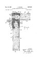
In the drawings, wherein, for the purpose of illustration, are shown several embodiments of the modular panels of my invention, the numeral 20 designates a modular panel of my invention generally. In FIGURE l, modular panel 20 is seen to comprise a border comprising spaced, insulated, outer coverings 26, opposed longitudinal reinforcing strips 30, U-shaped reinforcing strip 32 and insulating insert 31; opposed face plates 22 and 24 and insulation 34. The border of modular panel 20 is a peripherally closed figure. While I prefer to form modular panels of my invention in the form of rectangles, they may be formed in any other shape (as required by the particular installation). It should be noted that the border is generally U-shaped in cross-section with the open end of the U facing the inside of the panel.
While outer covering 26 may be smooth, it is preferably corrugated on portions of its outer surface as shown at 33. These corrugations aid in my obtaining good contact between adjacent panels when these panels are formed into walls, ceilings, rooms, etc. and also permit the installer in the field to obtain airtight and weather-tight joints without the field use of caulk or gaskets. When very large or heavy modular panels of my invention are fabricated or when the panels are used as floors, I have found it advisable to use braces 35 to prevent the face plates from buckling. While these braces are normally attached only to the facing sheets, they 'may be tied into the reinforcing strip 30 which is adjacent to the face plate being braced. The braces should not make contact with any other metallic element in the panel.
In FIGURE 1, there is shown one method of forming a corner using two modular panels of my invention. Angle brace 36 is affixed to one of the panels by means of metal self-tapping screw 42 and Z-brace 38 is affixed to the other modular panel by means of metal self-tapping screw 42. The two braces 36 and 38 are tied together by means of bolt 40. Other methods and means of joining modular panels of my invention may also be used as will be apparent as this description proceeds.
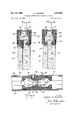
There is shown in FIGURE 4 a group of four panels joined to form a portion of a curtain wall. The upper two panels are shown in section along their center lines and the lower two panels are shown in elevation. Preferably, the borders of panels of my invention are formed in accordance with the illustration of FIGURE 4. Metal corner clip 58 is held to the two butting U-shaped reinforcing strips 32 by means of screws 60. Bolts, blind rivets, spot or tack welds may also be used to join the corner clip to the U-shaped reinforcing strip. The heads of screws 60 are not permitted to project beyond the panel edge and they are preferably covered with an insulating or sealing compound prior to joining the adjacent panels together. I prefer to treat all abutting surfaces with caulking compound, pressure sensitive cement, chemically curing rubber compound or similar material prior to yactually making the corner joint of modular panels of my invention.
In FIGURES 5 and 6, I have illustrated a second method for joining adjacent panels of my invention to form the wall of FIGURE 4. Commercially available locks which may be obtained from Simmons Fastener Corporation of Albany, New York, are used for the purpose of illustration. However, other locks may also be employed to join the panels of my invention together. Male element 66 is firmly attached to U-shaped reinforcing strip 32 of one panel and female element 68 is firmly attached to U- shaped reinforcing strip 32 of the adjacent panel. Openings are provided in both panels to permit the movable male element to move into the female member of the adjacent panel.
The male element 66 contains a movable rotary lock tongue 67 having outwardly-turned lips (not shown)y which mate with the inwardly-turned fianges 71 of the female element 68. A key (not shown) fits into recess 69 in male element 66 and is used to turn rotary lock tongue 67. Locking bars 73 are provided to cooperate with the serrations on rotary lock tongue 67 to prevent it from slipping after it has been locked in place. Opening 64 is provided in reinforcing strip 30 to provide a keyhole for the key. Plug 62 of flexible insulating material is inserted into the opening 64 after the panels are joined together and when the panels are stored prior to installation.
In FIGURES 2 and 3 there are illustrated two, embodiments of modular panels of my invention designed to provide both acoustic and thermal insulation. While the embodiment of FIGURE 2 is preferred, that of FIGURE 3 may be used equally satisfactorily. The border is formed in the same manner and of the same elements as have been previously described. In addition, insert 44 is placed as shown in FIGURE 2. Insert 44 is slotted as shown at 45. Face plates 24 are inserted in slots 28 and 45. as has been previously described and thermal insulation 34 is placed in the chamber formed Aby the two opposed face plates. Usually the thermalinsulation also fills the chamber formed by thel elements of the border but this may be prevented if it is deemed advisable to do so. This is accomplished by placing a nonmetallic barrier across the opening between the two longitudinal reinforcing strips 30.
In FIGURE 3, there is illustrated an alternative ernbodiment of combined thermal and acoustic modular panel. Face plate 24a is formed into a pan by turning up the sides as shown at 25. Face plates 24a and 48 are both inserted in one set of slots 28 as shown in the figure. Thermal insulation is placed between face plates 24 and 24a and acoustic insulation is placed between faceplates. 24a and 48. The advantage of the embodirnent of FIC.-
URE 2 resides in the fact that it is unnecessary to bend the face plate; while the embodiment of FIGURE 3 does not require a special insert 44 to be fabricated. There are instances when one embodiment should be employed and an equal number of instances when the other should be used.
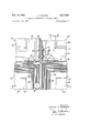
In FIGURES 7 and 8 there is illustrated a window panel which uses the same border as that of the modular panels which are used for insulation. One of the biggest advantages of this window panel is that it can be installed in curtain walls formed from modular panels of my invention without requiring any special fabrication of either of the panels in the eld. These window panels are particularly useful in installation where it is necessary to see what is occurring on the other side of the wall without changing the climatic conditions on the other side of the wall. This condition prevails in installations in steel rolling mill control rooms or pulpits, environmental test rooms, laboratories and like locations.
Modular panel a is assembled as follows: the border is assembled as described heretofore, inserts 70 are installed by fitting projections 82 into slots 28. Then the window panes are put in place. Now, groove inserts 72 are inserted into undercut grooves 78 and the modular panel is ready for installation in a Wall. The direction of installation of groove inserts 72 is determined by the thickness of the panes to be used with the modular panel. If two thick panes are to be installed in the panel, the position of the insert 72 on the left of FIGURE 8 must be reversed. If two thin panes are to be installed, the insert 72 on the right of FIGURE 8 must be reversed. If desired, modular panels of my invention may be used to hold a single pane of glass. Modular panel 20a may be used to hold special thermal glass windows, plate glass windows or face plates depending on the requirements of the particular installation.
While I prefer to form the borders of my modular panels without any of the insulated, outer covering overlying the bottom of the U of the U-shaped reinforcing strip, it is also within the contemplation of my invention to form the insulated, outer coverings of the border sections in one piece as shown in FIGURE ll.
Insulated, outer covering 90 is U-shaped in cross-section with the open end of the U facing toward the interior of the panel and is preferably formed of neoprene. Other insulators such as butyl or natural rubber, polyvinyl chloride or similar materials may be used also. Outer covering 90 is provided with slots 92 at the ends of the legs of the U and inwardly extending enlarged portions 94 near the base of the U. Longitudinal reinforcing strips 38 are embedded in the enlarged inwardly extending portions 94 as shown in the ligure. U-shaped reinforcing strip 32 contacts the inner portion of the base 96 of the U of the insulated, outer covering 90 and all the elements 9i), 38 and 32 are fused together by vulcanization or otherwise as has been set forth earlier in this description. An insert strip 31 is iitted around lip 37 of longitudinal reinforcing strip 30 and inserted in slot 92 to lill a portion of the slot when a thin face plate 24 is to be inserted in slot 92. The slots 92 of outer covering 90 are similar to the slots 28 of outer covering 26 of FIGURE l and the face plates are inserted therein in the same manner as has been described heretofore. Insulation 34 is inserted in the chamber between the face plates. The insulated, outer covering may be substituted for the spaced, outer coverings illustrated in all the other ligures of this application.
As shown in the figures, I prefer that each peripherally closed border used in modular panels of my invention be made up of U-shaped border sections which are beveled and connected together.
While I have disclosed my invention in relation to speciic examples and in speciiic embodiments, I do not wish to be limited thereto, for obvious modifications will occur to those skilled in the art without departing from the spirit and scope of my invention.
Having thus described my invention, I claim:
1, In a modular panel including a pair of opposed, laterally spaced face plates and a closed border around the periphery of the face plates establishing a closed chamber between the face plates, the border having laterally spaced opposite sides, a plurality of joined border sections establishing the border, each of said border sections comprising:
an outer covering of insulating material having inner and outer surfaces and a U-shaped lateral crosssection with opposite legs of the U-shape projecting inwardly from the periphery and terminating at innermost ends corresponding with the innermost end of the U-shaped cross-section, each leg including an enlarged portion extending toward one another;
iirst and second longitudinal reinforcing strips each embedded in one of said enlarged portions and each fused to the inner surface of one leg of the U-shaped border section;
a third longitudinal reinforcing strip having a U-shaped lateral cross-section and being disposed in the outer covering at the end of said U-shaped cross-section opposite said innermost end and fused to the inner surface of the outer covering; and
a longitudinal slot in each leg of the U-shaped border section extending outwardly from said innermost ends;
said face plates being received within said slots such that insulating material lies between the outer covering and each face plate, between each face plate and each of said first and second longitudinal reinforcing strips, and between each said first and second longitudinal reinforcing strips and the third longitudinal reinforcing strip so that the outer covering interrupts any direct contact between the opposed face plates and among the longitudinal reinforcing strips and the lateral path from one side to the other side of the peripheral bor-der is of low transmission.
2. A modular panel as described in claim 1 including insulating material placed in the chamber between the opposed face plates.
3. A modular panel as described in claim 1 including a plate located between the face plates so that the chamber is divided into two chambers, the outer periphery of the plate being bent toward one of the face plates and being received in the same slots as said face plate; acoustic insulating material being inserted in one of the two charnbers so formed and thermal insulating material being inserted in the other of the chambers so formed.
4. A modular panel as described in claim 1 wherein at least one of said longitudinal reinforcing strips has an inwardly-turned lip at the innermost end thereof facing toward the interior of the chamber a longitudinal, insulating strip aiiixed to the longitudinal reinforcing strip surrounding said inwardly-turned lip.
5. A modular panel as described in claim 4 wherein the longitudinal insulating strip surrounding the inwardlyturned lip of the longitudinal reinforcing strip has a slot therein and including a plate inserted in the slot, the plate being within the chamber such that the chamber is divided into two chambers, acoustic insulating material being inserted in one of the chambers so formed, and
thermal insulating material being inserted in the other of the chambers so formed.
6. In a modular panel including a pair of opposed, laterally spaced face plates and a closed border around the periphery of the face plates establishing a closed chamber between the face plates, the border having laterally spaced opposite sides, a plurality of joined border sections establishing the border, each of said border sections comprising:
an outer covering of insulating material having inner and outer surfaces and a U-shaped lateral crosssection with opposite legs of the U-shape projecting inwardly from the periphery and terminating at innermost ends corresponding with the innermost end of the U-shaped cross-section, each leg including an enlarged portion extending toward one another;
first and second longitudinal reinforcing strips each embedded in one of said enlarged portions and each fused to the inner surface of one leg of the U-shaped border section;
a third longitudinal reinforcing strip having a U-shaped lateral cross-section and being disposed in the outer covering at the end of said U-shaped cross-section opposite said innermost end and fused to the inner surface of the outer covering;
a longitudinal slot in each leg of the U-shaped border section extending outwardly from said innermost ends;
a longitudinal insulating strip having a pair of longitudinal projections from one surface thereof and a pair of longitudinal, undercut, parallel grooves with a single longitudinal projection between the grooves on the other surface thereof;
the pair of longitudinal projections from the one surface being received within said slots;
a pair of longitudinal L-shaped inserts reversibly insertable in the longitudinal, undercut, parallel grooves so as to form a third slot between one of the L-shaped inserts and the single longitudinal projection and a fourth slot between the other of the L-shaped inserts and the single longitudinal projection;
said face plates being received within said third and fourth slots such that insulating material lies between the outer covering and each face plate, between each face plate and each of said first and second longitudinal reinforcing strips, and between each said first and second longitudinal reinforcing strips and the third longitudinal reinforcing strip so that the outer covering interrupts any direct contact between the opposed face plates and among the longitudinal reinforcing strips and the lateral path from one side to the other side of the peripheral border is of low transmission.
7. A modular panel as described in claim 6 wherein the plates are formed of a transparent material.
8. In a modular panel including a pair of opposed, laterally spaced face plates and a closed border around the periphery of the face plates establishing a closed chamber between the face plates, the border having laterally spaced opposite sides and a U-shaped lateral crosssection, a plurality of joined border sections establishing the border, each of said border sections comprising:
a pair of spaced outer coverings of insulating material each having inner and outer surfaces, each of the outer coverings projecting inwardly from the periphery and terminating at innermost ends corresponding with the innermost end of the U-shaped cross-section, each inner surface including an enlarged portion extending toward one another;
first and second longitudinal reinforcing strips each embedded in one of said enlarged portions and each fused to the inner surface of one of the outer coverings;
a third longitudinal reinforcing strip having a U-shaped lateral cross-section and being disposed between the 8 outer coverings at the end of said U-shaped crosssection opposite said innermost end and fused to the inner surfaces of the outer coverings; and
a longitudinal slot in each outer covering of the U- shaped border section extending outwardly from said innermost ends;
said face plates being received within said slots such that insulating material lies between the outer covering and each face plate, between each face plate and each of said rst and second longitudinal reinforcing strips, and between each said rst and second longitudinal reinforcing strips and the third longitudinal reinforcing strip so that the outer covering interrupts any direct contact between-'the opposed face plates and among the longitudinal reinforcing strips and the lateral path from one side to the other side of the peripheral border is of low transmission.
9. A modular panel as described in claim 8 including insulating material placed in the chamber between the opposed face plates.
10. A modular panel as described in claim 9 including a plate located between the face plates so that the chamber is divided into two chambers, the outer periphery of the plate being bent toward one of the face plates and Ibeing received in the same slots as said face plates; acoustic insulating material being inserted in one of the two chambers so formed and thermal insulating material being inserted in the other of the chambers so formed.
11. A modular panel as described in claim 9 wherein at least one of said longitudinal reinforcing strips has an inwardly-turned lip at the innermost end thereof facing toward the interior of the chamber -a longitudinal, insulating strip affixed to the longitudinal reinforcing strip surrounding said inwardly-turned lip.
'12. A modular panel as described in claim 11 wherein the longitudinal insulating strip surrounding the inwardlyturned lip of the longitudinal reinforcing strip has a slot therein and including a plate inserted in the slot, the plate being within the chamber such that the chamber is divided into two chambers, acoustic Ainsulating material being inserted in one of the chambers so formed, and thermal insulating material being inserted in the other of the chambers so formed.
13. In a modular panel including a pair of opposed, laterally spaced face plates and a closed border around the periphery of the face plates establishing a closed chamber between the face plates, the border having laterally spaced opposite sides and a U-shaped later-al cross-section, a vplurality of joined border sections establishing kthe border, each of said border sections cornprising:
a pair of spaced outer coverings of insulating material each having inner and outer surfaces, each of the outer coverings Vprojecting inwardly from the periphery and terminating at innermost ends corresponding with the innermost end of the U-shaped cross-section, each inner surface including an enlarged portion extending toward one another;
rst and second longitudinal reinforcing strips each embedded `in one of said enlarged portions and each fused to the inner surface of one of the outer cover- 1ngs;
a third longitudinal reinforcing strip having a U-shaped lateral cross-section and being disposed between the outer coverings at the end of said U-shaped crosssection opposite said innermost end and fused to the inner surfaces of the outer coverings;
a longitudinal slot in each outer covering of the U- shaped border section extending outwardly from said innermost ends;
a longitudinal insulating strip having a pair of longitudinal projections from one surface thereof and a pair of longitudinal, undercut, parallel grooves with `a single longitudinal projection between the grooves on the other surface thereof;
the pair of longitudinal projections from the one surface being received within said slots;
a pair of longitudinal L-shaped inserts reversibly insertable in the longitudinal, undercut, parallel grooves so as to form a third slot between one of the L-shaped inserts and the single longitudinal projection and a fourth slot between the other of the L-shaped inserts and the single longitudinal projection;
said face plates being received within said third and fourth slots such that insulating material lies between the outer covering and each face plate, between each face plate and each of said first and sec- -ond longitudinal reinforcing strips, and between each said first and second longitudinal reinforcing ystrips and the third longitudinal reinforcing strip so that the outer covering interrupts any direct contact between the opposed face plates and among the longitudinal reinforcing strips and the lateral path from ione side to the other side of the peripheral border is of low transmission.
14. A modular panel las described in claim 13 wherein the plates are formed of a transparent material.
15. In a wall including a plurality of joined modular panels, in which at least one of said modular panels includes a pair of opposed, laterally spaced face plates and a closed border -around the periphery of the face plates establishing a closed chamber between the face plates, the border having laterally spaced opposite sides from the periphery, a plurality of joined border sections establishing the border, each of said border sections comprising:
an outer covering of insulating material having inner and outer surfaces and a U-shaped lateral cross-section with opposite legs of the U-shaped projecting inwardly from the periphery and terminating at innermost ends corresponding with the innermost end of the U-shaped cross-section, each leg including an enlarged portion extending toward one another;
first and second longitudinal reinforcing strips each embedded in one of said enlarged portions and each fused to the inner surface of one leg of the U-shaped border section;
a third longitudinal reinforcing strip having a U-shaped lateral cross-section and being disposed in the outer covering at the end of said U-shaped cross-section lopposite said innermost end and fused to the inner surface of the outer covering; and
a longitudinal slot in each leg of the U-shaped border section extending outwardly from said innermost ends;
said face plates being received within said slots such that insulating material lies between the outer covering and each face plate, between each face plate and each of said first and second longitudinal reinforcing strips, and between each said rst and second longitudinal reinforcing strips and the third longitudinal reinforcing strip so that the outer covering interrupts any direct contact between the opposed face plates and among the longitudinal reinforcing strips and the lateral path from one side to the other side of the peripheral border is of low transmission.
16. In a wall including a plurality of joined modular panels, in which at least one -of said modular panels includes a pair of opposed, laterally spaced face plates and a closed border around the periphery of the face plates establishing a closed chamber between the face plates, the border having laterally spaced opposite sides and Aa U-shaped lateral cross-section, a plurality of joined border sections establishing the border, each of said border sections comprising:
a pair of spaced outer coverings of insulating material each having inner and outer surfaces, each of the outer coverings projecting inwardly from the periphery and terminating at innermost ends corresponding with the innermost end of the U-shaped cross-section, each inner surface including an enlarged portion extending toward one another;
first and second longitudinal reinforcing strips each embedded in one of said enlarged portions and each fused to the inner surface of one of the outer coverings;
a third longitudinal reinforcing strip having a U-shaped lateral cross-section and being disposed between the outer coverings at the end of `said U-Shaped crosssection opposite said innermost end and fused to the inner surfaces of the outer coverings; and
a longitudinal slot in each outer covering of the U- shaped border section extending outwardly from said innermost ends;
said face plates being received within said slots such that insulating material lies between the outer covering and each face plate, between each face plate and each of said irst and second longitudinal reinforcing strips, and between each said rst and second longitudinal reinforcing strips and the third longitudinal reinforcing strip so that the outer covering interrupts any direct contact between the opposed face plates and among the longitudinal reinforcing strips and the lateral path from one side to the other side of the peripheral border is of low transmission.
References Cited by the Examiner UNITED STATES PATENTS 2,099,597 11/ 1937 Carr 20-69 2,197,913 4/1940 Axe 20-56.5 X 2,303,149 11/1942 Verhagen 2056.5 X 2,575,854 11/1951 Verhagen 52-127 2,585,082 2/1952 Bollinger 52-619 X 2,670,508 3/ 1954 Sylvan 20-56.5 2,833,003 5/1958 Bourne et al. 52-620 2,893,068 7/ 1959 Johnson et al. 52-474 FRANK L. ABBOTT, Primary Examiner.
JACOB L. NACKENOFF, Examiner,
Claims (1)
15. IN A WALL INCLUDING A PLURALITY OF JOINED MODULAR PANELS, IN WHICH AT LEAST ONE OF SAID MODULAR PANELS INCLUDES A PAIR OF OPPOSED, LATERALLY SPACED FACE PLATES AND A CLOSED BORDER AROUND THE PERIPHERY OF THE FACE PLATES ESTABLISHING A CLOSED CHAMBER BETWEEN THE FACE PLATES, THE BORDER HAVING LATERALLY SPACED OPPOSITE SIDES FROM THE PERIPHERY, A PLURALITY OF JOINED BORDER SECTIONS ESTABLISHING THE BORDER, EACH OF SAID BORDER SECTIONS COMPRISING: AN OUTER COVERING OF INSULATING MATERIAL HAVING INNER AND OUTER SURFACES AND A U-SHAPED LATERAL CROSS-SECTION WITH OPPOSITE LEGS OF U-SHAPED PROJECTING INWARDLY FROM THE PERIPHERY AND TERMINATING AT INNERMOST ENDS CORRESPONDING WITH THE INNERMOST END OF THE U-SHAPED CROSS-SECTION, EACH LEG INCLUDING AN ENLARGED PORTION EXTENDING TOWARD ONE ANOTHER; FIRST AND SECOND LONGITUDINAL REINFORCING STRIPS EACH EMBEDDED IN ONE OF SAID ENLARGED PORTIONS AND EACH FUSED TO THE INNER SURFACE OF ONE LEG OF THE U-SHAPED BORDER SECTION; A THIRD LONGITUDINAL REINFORCING STRIP HAVING A U-SHAPED LATERAL CROSS-SECTION AND BEING DISPOSED IN THE OUTER COVERING AT THE END OF SAID U-SHAPED CROSS-SECTION OPPOSITE SAID INNERMOST END AND FUSED TO THE INNER SURFACE OF THE OUTER COVERING; AND A LONGITUDINAL SLOT IN EACH LEG OF THE U-SHAPED BORDER SECTION EXTENDING OUTWARDLY FROM SAID INNERMOST ENDS; SAID FACE PLATES BEING RECEIVED WITHIN SAID SLOTS SUCH THAT INSULATING MATERIAL LIES BETWEEN THE OUTER COVERING AND EACH FACSE PLATE, BETWEEN EACH FACE PLATE AND EACH OF SAID FIRST AND SECOND LONGITUDINAL REINFORCING STRIPS, AND BETWEEN EACH OF SAID FIRST AND SECOND LONGITUDINAL REINFORCING STRIPS AND THE THIRD LONGITUDINAL REINFORCING STRIP SO THAT THE OUTER COVERING INTERRUPTS ANY DIRECT CONTACT BETWEEN THE OPPOSED FACE PLATES AND AMONG THE LONGITUDINAL REINFORCING STRIPS AND THE LATERAL PATH FROM ONE SIDE TO THE OTHER SIDE OF THE PERIPHERAL BORDER IS OF LOW TRANSMISSION.
Priority Applications (1)
| Application Number | Priority Date | Filing Date | Title |
|---|---|---|---|
| US399803A US3217455A (en) | 1964-09-28 | 1964-09-28 | Building construction of modular panels |
Applications Claiming Priority (1)
| Application Number | Priority Date | Filing Date | Title |
|---|---|---|---|
| US399803A US3217455A (en) | 1964-09-28 | 1964-09-28 | Building construction of modular panels |
Publications (1)
| Publication Number | Publication Date |
|---|---|
| US3217455A true US3217455A (en) | 1965-11-16 |
Family
ID=23581026
Family Applications (1)
| Application Number | Title | Priority Date | Filing Date |
|---|---|---|---|
| US399803A Expired - Lifetime US3217455A (en) | 1964-09-28 | 1964-09-28 | Building construction of modular panels |
Country Status (1)
| Country | Link |
|---|---|
| US (1) | US3217455A (en) |
Cited By (14)
| Publication number | Priority date | Publication date | Assignee | Title |
|---|---|---|---|---|
| US3832812A (en) * | 1972-06-06 | 1974-09-03 | Annapolis Yacht Yard Inc | Fire retardant insulated modular building panels |
| US3834101A (en) * | 1972-08-25 | 1974-09-10 | Mesker Ind Inc | Insulated door construction |
| US3983672A (en) * | 1971-04-05 | 1976-10-05 | Dietrich Richard J | Wall |
| US5634302A (en) * | 1995-04-17 | 1997-06-03 | Lee; Wen-Yuan | Device for temporarily positioning a frame to be connected securely to a concrete wall during construction of the concrete wall |
| US5687529A (en) * | 1996-06-07 | 1997-11-18 | Worldtec Systems, Inc. | Fastening device |
| US6421972B1 (en) | 2000-04-27 | 2002-07-23 | I Mozaic Trust | Modular wall component with insulative thermal break |
| FR2827894A1 (en) * | 2001-07-27 | 2003-01-31 | Usinor | Roofing material for building has self-supporting under-layer of rigid interlocking lengthwise panels with insulating cores |
| US20070033891A1 (en) * | 2003-09-22 | 2007-02-15 | Imbabi Mohammed S | Support panel |
| WO2009086617A1 (en) | 2008-01-08 | 2009-07-16 | Ano Leo | Prefabricated building components and assembly equipments |
| US20100095634A1 (en) * | 2007-09-27 | 2010-04-22 | Caterpillar Japan Ltd. | Door panel |
| US20100281784A1 (en) * | 2008-01-08 | 2010-11-11 | Ano Leo | Prefabricated building components and assembly equipments |
| US20130074431A1 (en) * | 2010-12-06 | 2013-03-28 | Scott Croasdale | System and methods for thermal isolation of components used |
| US9856655B2 (en) | 2013-03-14 | 2018-01-02 | Modern Framing Systems, LLC | Modular system for continuously insulating exterior walls of a structure and securing exterior cladding to the structure |
| US11383276B2 (en) * | 2019-09-13 | 2022-07-12 | Rdbj, Llc | Lumber use designation system and method |
Citations (8)
| Publication number | Priority date | Publication date | Assignee | Title |
|---|---|---|---|---|
| US2099597A (en) * | 1936-03-30 | 1937-11-16 | Jr Frank L Carr | Weather strip for metal sash windows |
| US2197913A (en) * | 1939-01-30 | 1940-04-23 | Om Edwards Co Inc | Window construction |
| US2303149A (en) * | 1940-01-20 | 1942-11-24 | Adlake Co | Rubber glazing strip for multiple glass sash |
| US2575854A (en) * | 1946-10-21 | 1951-11-20 | Adlake Co | Sash |
| US2585082A (en) * | 1947-01-02 | 1952-02-12 | Jr George H Bollinger | Insulated metal panel |
| US2670508A (en) * | 1951-05-26 | 1954-03-02 | Sylvan Joseph | Double pane sash assembly |
| US2833003A (en) * | 1954-11-22 | 1958-05-06 | Joseph B Bourne | Structural panel |
| US2893068A (en) * | 1956-12-17 | 1959-07-07 | Douglas Aircraft Co Inc | Adhesive insulation clip |
-
1964
- 1964-09-28 US US399803A patent/US3217455A/en not_active Expired - Lifetime
Patent Citations (8)
| Publication number | Priority date | Publication date | Assignee | Title |
|---|---|---|---|---|
| US2099597A (en) * | 1936-03-30 | 1937-11-16 | Jr Frank L Carr | Weather strip for metal sash windows |
| US2197913A (en) * | 1939-01-30 | 1940-04-23 | Om Edwards Co Inc | Window construction |
| US2303149A (en) * | 1940-01-20 | 1942-11-24 | Adlake Co | Rubber glazing strip for multiple glass sash |
| US2575854A (en) * | 1946-10-21 | 1951-11-20 | Adlake Co | Sash |
| US2585082A (en) * | 1947-01-02 | 1952-02-12 | Jr George H Bollinger | Insulated metal panel |
| US2670508A (en) * | 1951-05-26 | 1954-03-02 | Sylvan Joseph | Double pane sash assembly |
| US2833003A (en) * | 1954-11-22 | 1958-05-06 | Joseph B Bourne | Structural panel |
| US2893068A (en) * | 1956-12-17 | 1959-07-07 | Douglas Aircraft Co Inc | Adhesive insulation clip |
Cited By (23)
| Publication number | Priority date | Publication date | Assignee | Title |
|---|---|---|---|---|
| US3983672A (en) * | 1971-04-05 | 1976-10-05 | Dietrich Richard J | Wall |
| US3832812A (en) * | 1972-06-06 | 1974-09-03 | Annapolis Yacht Yard Inc | Fire retardant insulated modular building panels |
| US3834101A (en) * | 1972-08-25 | 1974-09-10 | Mesker Ind Inc | Insulated door construction |
| US5634302A (en) * | 1995-04-17 | 1997-06-03 | Lee; Wen-Yuan | Device for temporarily positioning a frame to be connected securely to a concrete wall during construction of the concrete wall |
| US5687529A (en) * | 1996-06-07 | 1997-11-18 | Worldtec Systems, Inc. | Fastening device |
| US6421972B1 (en) | 2000-04-27 | 2002-07-23 | I Mozaic Trust | Modular wall component with insulative thermal break |
| US6857237B1 (en) * | 2000-04-27 | 2005-02-22 | I Mozaic Trust | Modular wall component with insulative thermal break |
| FR2827894A1 (en) * | 2001-07-27 | 2003-01-31 | Usinor | Roofing material for building has self-supporting under-layer of rigid interlocking lengthwise panels with insulating cores |
| US20070033891A1 (en) * | 2003-09-22 | 2007-02-15 | Imbabi Mohammed S | Support panel |
| US20100095634A1 (en) * | 2007-09-27 | 2010-04-22 | Caterpillar Japan Ltd. | Door panel |
| US7934354B2 (en) * | 2007-09-27 | 2011-05-03 | Caterpillar S.A.R.L. | Door panel |
| WO2009086617A1 (en) | 2008-01-08 | 2009-07-16 | Ano Leo | Prefabricated building components and assembly equipments |
| US20100281784A1 (en) * | 2008-01-08 | 2010-11-11 | Ano Leo | Prefabricated building components and assembly equipments |
| US20110120049A1 (en) * | 2008-01-08 | 2011-05-26 | Ano Leo | Prefabricated Building Components and Assembly Equipment |
| US20150184376A1 (en) * | 2010-12-06 | 2015-07-02 | Scott Croasdale | System and methods for thermal isolation of components used |
| US8973334B2 (en) * | 2010-12-06 | 2015-03-10 | Scott Croasdale | System and methods for thermal isolation of components used |
| US20130074431A1 (en) * | 2010-12-06 | 2013-03-28 | Scott Croasdale | System and methods for thermal isolation of components used |
| US9677268B2 (en) | 2010-12-06 | 2017-06-13 | Douglas James Knight | System and methods for thermal isolation of components used |
| US9732518B2 (en) * | 2010-12-06 | 2017-08-15 | Scott Croasdale | System and methods for thermal isolation of components used |
| US9856655B2 (en) | 2013-03-14 | 2018-01-02 | Modern Framing Systems, LLC | Modular system for continuously insulating exterior walls of a structure and securing exterior cladding to the structure |
| US11383276B2 (en) * | 2019-09-13 | 2022-07-12 | Rdbj, Llc | Lumber use designation system and method |
| US20220288643A1 (en) * | 2019-09-13 | 2022-09-15 | Rdbj, Llc | Lumber Use Designation System and Method |
| US11878326B2 (en) * | 2019-09-13 | 2024-01-23 | Spectrum 28, Llc | Lumber use designation system and method |
Similar Documents
| Publication | Publication Date | Title |
|---|---|---|
| US5394664A (en) | Interlocking skylight and roof panel assembly | |
| US3217455A (en) | Building construction of modular panels | |
| US3310917A (en) | Building construction and modular panels therefor | |
| US3750333A (en) | Insulated prime door | |
| US5062250A (en) | Insulating panel system, panels and connectors therefor | |
| US3535844A (en) | Structural panels | |
| US3052330A (en) | Curtain wall assembly | |
| US3788021A (en) | Interconnection system for structural elements | |
| US4207717A (en) | System for improving heat insulating characteristics of existing curtain walls and the like | |
| US3363383A (en) | Joint structures | |
| US3305986A (en) | Insulated enclosures and panels therefor | |
| US3093217A (en) | Insulating unit for curtain wall | |
| US3797190A (en) | Prefabricated, insulated, metal wall panel | |
| US3386218A (en) | Building panel with ribbed sealing element between overlapping edges | |
| US4936069A (en) | Modular building panel having an improved offset thermal barrier joint | |
| US4316351A (en) | Thermally insulated building construction panel and a wall formed from such panels | |
| US3703063A (en) | Profile member for windows, doors, facades, or the like | |
| US3553918A (en) | Insulated curtain wall construction | |
| US3777430A (en) | Complementary mating elements for double-skin foam core panel | |
| US4608796A (en) | Multiple pane glass unit | |
| US5247770A (en) | Exterior composite foam panel wall joint design | |
| US3300934A (en) | Building outer wall structure | |
| US5560155A (en) | Modular solarium | |
| US3238679A (en) | Prefabricated window finishing and framing member | |
| US4716702A (en) | Edge-to-edge panel connection |