US3217618A - Catch basin structure - Google Patents
Catch basin structure Download PDFInfo
- Publication number
- US3217618A US3217618A US153163A US15316361A US3217618A US 3217618 A US3217618 A US 3217618A US 153163 A US153163 A US 153163A US 15316361 A US15316361 A US 15316361A US 3217618 A US3217618 A US 3217618A
- Authority
- US
- United States
- Prior art keywords
- side walls
- mounting
- fitting
- upstanding
- paving material
- Prior art date
- Legal status (The legal status is an assumption and is not a legal conclusion. Google has not performed a legal analysis and makes no representation as to the accuracy of the status listed.)
- Expired - Lifetime
Links
Images

Classifications
-
- E—FIXED CONSTRUCTIONS
- E03—WATER SUPPLY; SEWERAGE
- E03F—SEWERS; CESSPOOLS
- E03F5/00—Sewerage structures
- E03F5/04—Gullies inlets, road sinks, floor drains with or without odour seals or sediment traps
- E03F5/046—Gullies inlets, road sinks, floor drains with or without odour seals or sediment traps adapted to be used with kerbs
Definitions
- the subject invention relates generally to drains and more particularly is directed to improvements in what is commonly referred to as a catch basin or construction primarily adapted for use in conjunction with a gutter.
- catch basin constructions there are many forms of conventional catch basin constructions in use and each usually includes a heavy metal casting or mounting which is supported on a masonry foundation which forms a well leading to a storm sewer.
- the foundation constitutes a permanent installation and the same is substantially true of the mounting as it is customarily embedded in a layer of paving material.
- the principal object of the invention is to provide a fitting or accessory which may be used with the mounting of a conventional catch basin construction in a manner whereby it is not necessary to remove and reinstall the mounting when a new layer of paving material is laid upon an original or bottom layer, thereby overcoming the disadvantages inherent in the customary setup above referred to.
- an important object of the invention is to provide a fitting which is preferably made rectangular or square in shape and includes a vertical front wall, a pair of corresponding vertical parallel side walls, and a brace joining the side walls and forming a vertical rear wall disposed parallel to the front wall.
- the front and side walls are preferably respectively provided with radial portions or flanges which are joined to form a continuous flange surrounding these walls for support upon the upper surface of an original layer of paving material and so that a new layer will overlay and embed such radial portions or flange.
- Another object of the invention is to provide a fitting which can be readily supported on a conventional mounting to replace a conventional cover, grid or grating and a seat on the fitting for receiving the cover.
- a specific object of the invention is to provide a fitting of the character above described in which its radially extending portions are provided with relatively large axial openings which are adapted to receive a new layer of paving material and thereby assist in securing the fitting in place. If found desirable, fastening means may be extended through the openings into the original layer and/ or the new layer to additionally assist in anchoring the fitting in relation to the mounting as well as both layers of paving material.
- the invention also offers advantages with respect to eificiency, adaptability, stability and durability.
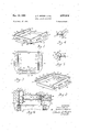
- FIGURE 1 is a perspective view of a fitting embodying the invention
- FIGURE 2 is another perspective view of the fitting
- FIGURE 3 is a top view of the fitting
- FIGURE 4 is a transverse section taken substantially on line 4-4 of FIGURE 3;
- FIGURE 5 is a transverse section taken substantially on line 5-5 of FIGURE 3;
- FIGURE 6 is a partial vertical section showing the fitting installed for use
- FIGURES 7 through 12 illustrate a modified form of fitting and FIGURES 7 and 8 are perspective views of such fitting;
- FIGURE 9 is a top plan view of the fitting
- FIGURE 10 is a partial transverse section taken substantially on line 10-10 of FIGURE 9;
- FIGURE 11 is a partial transverse section taken substantially on line 11-41 of FIGURE 9;
- FIGURE 12 is a partial vertical section exemplifying the mode of installing the fitting.
- FIGURE 13 is a partial vertical section taken through a portion of the fitting showing the shape of an opening in said portion.
- numeral 1 represents a masonry foundation located adjacent a gutter having a curb and forming a well 2 which is communicatively connected with a storm sewer not shown.
- a metal casting or mounting 3 has base flanges supported on the foundation and may be held in place by earth 4 adjacent the curb and by an original layer 5 of paving material laid on a bed 6.
- the mounting is preferably rectangular or square in shape and includes a vertical front wall 7, a pair of corresponding vertical parallel side walls 8 (only one is shown) and a vertical rear Wall 9 parallel to said front wall.
- the front wall 7 is provided with a shoulder 10 and. the side walls with shoulders 11.
- shoulders actually provide a substantially continuous squared or generally U-shaped seat for a fitting or member generally designated 12.
- Each of the shoulders is preferably interrupted to provide a notch 13 for receiving a projection or lug 14 formed integrally on each of the side and front walls of the fitting 12 in order to assist in locating and stabilizing the position of the fitting.
- a vertical casing or housing 15 has a lower extremity disposed in the mounting 3 against the side walls 8 and rear wall E and an upper extremity extending above the mounting to constitute a part of the curb. More specifically, this casing in interposed in the curb to conform generally therewith and includes a rear wall 16, a pair of side walls 17 (only one shown), and an overhanging top wall 18. The casing is preferably detachably connected to the mounting by bolts or screws 19 extending through the lower portions of the side walls 17 of the casing and the side walls 8 of the mounting.
- the fitting 12 generally constitutes a vertical continuation of the mounting and preferably includes a vertical front wall 20, a pair of corresponding vertical parallel side walls 21 (only one is shown), and a brace or bridge 22 joining the side walls and constituting .a vertical rear wall parallel to the front wall.
- the lower portions of the front and side walls of the fitting rest upon the seat formed by the shoulders 10 and 11 on the mounting and upper portions 23 of these walls provide a substantially U-shaped or squared seat for a cover or grid 24-, the latter having been previously removed from the mounting.
- the upper portions 23 are preferably interrupted to provide three notches 25 for receiving an integral depending projection 26 provided on a front rail 27 of the cover and a pair of projections 28 provided on side rails (only one is shown) of the cover to assist in locating and stabilizing its position on the fitting and prevent movement thereof toward the casing 15.
- the front wall 20 of the fitting is preferably provided With an inwardly extending lip 29 to assist in reinforcing this wall.
- the upper extremity of the front wall 20 of the fitting is preferably enlarged to provide an upturned vertical wall 30 offset outwardly from the front wall and the upper extremities of the side walls 21 are preferably enlarged to provide a pair of upturned vertical walls 31 offset outwardly from the side walls.
- the height of these upturned walls is substantially equal to the thickness of the cover so the latter is confined by such walls and sets flush with their upper surfaces.
- the fitting is also preferably constructed to provide each of the front and side walls with an outwardly extending portion or flange 32, which flanges are joined to form a squared or substantially U-shaped continuous flange surrounding the walls 20 and 21.
- Each of the flanges or portions 32 is preferably provided with a depending lip 33 for engaging the upper surface of a lower layer of paving material.
- the portion 32 at each side of the fitting may be provided with a pair of relatively large oblong openings and the portion at the front with relatively large oblong openings so that paving material may extend through the openings to assist in anchoring the flanges or portions 32 to the layers of paving material.
- an inner portion of the fitting and an inner portion of the cover extend into the casing 15 and that a depending portion 35 of the casing in combination with the cover defines an opening 36 of a size which resists or prevents to some extent the flow of foreign material, such as branches of trees, into the Well 2 formed by the foundation.
- the cover 24 also serves this purpose in addition to promoting safety and substantially preventing packed leaves from entering the Well.
- FIGURE 6 the installation exemplified in FIGURE 6 is preferably accomplished by removing the cover from the mounting 3 and laying it aside.
- a bed 37 of a new or top layer 38 of paving material is then placed upon the original or bottom layer and worked about the front and side Walls of the mounting, after which the fitting is placed on the mounting and the bed so that portions of the material will ooze or flow upwardly into or through the openings if provided in the flanges 32.
- the new material is then worked about the fitting and over its flanges, as indicated at 39, so that the upper surface of the new layer is flush with the upper surface or surfaces of the fitting, after which the material is allowed to set and harden.
- the cover 24 or a member which is imperforate may be placed on the fitting before material is worked over the flanges of the fitting in order to substantially prevent entry of the material into the well during the paving operation.
- the fitting can be placed on the mounting without first laying a bed therefor, in which event, the new paving material is worked under its flanges and thereover.
- the paving material flowing into the openings constitutes means extending therethrough for joining or connecting the overlying and underlying portions of the paving material together.
- the original layer of paving material about the mounting may become loose, and this and possible additional material may be removed to provide a trench or cavity Which is filled with the new paving material.
- the bed material may not always ooze or flow upwardly through openings in the flanges, if provided therein, depending on the height of the bed which is being laid, in which event, overlying material will flow downwardly through the openings to effect a connection with the bed below the flanges.
- the fitting may be installed so that these flanges may be constructed for engagement with the original layer Without first laying a bed of new material under the flanges.
- FIG. 1112 A conventional mounting generally designated 1112 is provided with a base flange 103 seated on the foundation.
- This mounting has a rear vertical wall 104 disposed generally in alignrnent with aligned portions of curbing (not shown), a pair of correspond ing parallel vertical Walls 1% (only one shown) projecting outwardly from the rear wall, and a front vertical wall 106 disposed parallel to the rear wall.
- the casing is preferably detachably secured to the mounting by means of bolts 111 or equiv alent means which extend through the side walls of the mounting and lower portions of the side walls of the casing as shown in FIGURE 12.
- the casing is secured in an upstanding position in alignment with adjacent portions of the curbing to constitute a portion thereof to promote continuity.
- Soil 112 is backed against the rear wall of the mounting and an upper portion of the rear wall on a level with or below that of the top wall of the casing.
- the front flange 113 is provided with a recess 115 and each of the side flanges with a recess 116.
- the inturned flanges 113 and 114 provide a squared seat or area for a fitting generally designated 117.
- the fitting 117 is generally rectilinear in shape to" correspond generally with the shape of the mounting for support thereon to constitute a vertical continuation thereof.
- This fitting is preferably cast and includes, among other things, a front vertical wall structure generally designated 118, a pair of parallel vertical wall structures generally designated 119 and a bridge or bar 120 joins the rear ends of the side wall structures as clearly exemplified in FIGURES 7, 8 and 9.
- the front wall structure 118 includes an upper up wardly extending portion 121 disposed in a vertical plane and a lower portion 122 disposed in a plane offset inward ly from the portion 121 in a manner whereby to provide an internal horizontal rest or seat 123 having a recess 124 interrupting its upper surface.
- This front wall structure is further preferably formed with a horizontal per tion or flange 125 extending forwardly from the juncture between the upper and lower vertical portions 121 and 122.
- the flange 125 is preferably provided with a plurality of two spaced elongate corresponding openings 126 extending in parallel relation to the upper portion 121.
- the side wall structures 119 are substantially identical and each preferably includes an upper upwardly extend ing portion 127 and a lower depending vertical portion 123 which is offset inwardly in a plane relative to the plane of the upper portion.
- the depending portion 128 is provided with an upper horizontal planar surface forming a rest or seat 129 which is interrupted to provide a recess 130 similar to the recess 124 provided in the portion 122 of the front wall structure.
- Each of the side wall structures is also preferably provided with a horizontal portion or flange 131 extending outwardly from the junction between its upper and lower portions 127 and 128, with a pair of spaced elongate openings 132 and 133 of different sizes in the flange.
- the upper portions of the front and side walls in combination with the inturned portions thereof define a large recess, socket or receiving means for a cover which will be described subsequently.
- the bridge 120 has an upper surface which defines a rest or seat 134 which is interrupted by a recess 135 similar to the recesses 124 and 130 above referred to. It will be noted that the lower surface of the bridge is preferably disposed in a plane formed by the lower surfaces of the depending portions of the side wall structures 119.
- front or radial flange 125 and the side flanges 131 are preferably joined, disposed in the same plane, and partially surround the wall structures.
- These flanges serve to reenforce the wall structures and provide a relatively large surface area or areas which overlie a lower layer of paving material 136 carried by a bed 137, as depicted in FIGURE 12.
- the bed 137 may be soil, base or back fill material and surrounds the foundation and the mounting and may be part of or different from the soil 112.
- the openings provided in the flanges serve to receive some of the material of an upper or top layer of paving material 138 which overlies the flanges and/ or portions of the lower layer in order to assist in stabilizing and anchoring the fitting for embedment between such layers or paving material.
- a conventional cover or grid 139 has four depending projections or lugs 140 (only two are shown) which are respectively received in the recesses 124, 130 and 135 when the cover is normally seated in the fitting on the inturned flanges and bridge thereof.
- the operation or pnocedure usually followed in installing the fitting comprises the act of conditioning the lower layer of paving material about the mounting by removing any loose material to provide a shallow cavity or trench about the mounting, which is filled by cement, mortar or of the same material as the top layer to form a substantial base for the horizontal flanges 125 and 131 and so that portions of this base material may flow or ooze upwardly into the openings provided in these flanges when the fitting is placed on the mounting. If found desirable, any loose material may be left in place, in which event some base material in a soft condition can be worked between the parts of loose material to bond them together and to the lower layer.
- the fitting may be placed on the mounting without trenching about the latter so that the flanges overlie and are supported on the said lower layer.
- the cover is removed from the mounting, after which the fitting is placed on the mounting so that the lower depending portions 128 of the side wall structures may find support on the inturned side portions 114 of the mounting with the bridge and/ or rear extremities of the side wall structure engaging the side walls 108 of the casing to limit inward movement of the fitting.
- the upper layer of paving material is applied and packed firmly into place about the fitting at a level flush with the upper surface of the fitting, whereupon the cover is mounted in the fitting as described above and illustrated in FIGURE 12.
- the cover can be placed on the fitting prior to placing the latter on the mounting.
- the rear extremities of the side flanges 131 are preferably bevelled as indicated at 141; that the depending portions 128 of the side wall structures terminate below a lower edge of the depending portion of the front wall structure; and that the frontal extremities of the depending portions 128 are preferably notched as indicated at 142 in order that the bevels and notches will provide clearance and facilitate installation of the fitting on various forms of mountings currently in use.
- the depending portions 128 and the recesses 124, 130 and 135 are preferably tapered in order to facilitate piloting of the fitting into the mounting and piloting of the cover into the fitting and afford what might be termed a cam or binding fit to dampen vibration between the components.
- pins or fasten- 6 ing means 143 can be extended through the openings 126, 132 and 133 in a manner whereby to assist in anchoring the fitting to the paving material.
- any one of the lateral portions or flanges of the fitting may be provided with one or more openings 144 of a tapered shape, the purpose of which is to assist in anchoring the fitting in place. It will be observed that the opening is preferably of a dovetail character with its marginal edges diverging downwardly.
- a member adapted for disposition relative to a mounting in paving material said member being of a onepiece construction and comprising a rectilinear formation and also plate means adapted for disposition in paving material, said rectilinear formation having an upper offset extremity and a lower inset extremity, said upper extremity comprising a pair of parallel upstanding side walls and an upstanding front wall disposed transverse to and joining said side walls, said lower extremity comprising a pair of parallel depending side walls, a bridge joining said upstanding and depending side walls and disposed in parallel relation to said upstanding front wall, said depending side walls having upper surfaces defining in combination with said upstanding walls an internal recess adapted to receive an apertured cover, said plate means projecting laterally outward an extent which is appreciably greater than the wall thickness of said rectilinear formation and so that said lower extremity projects below said plate means for disposition in an internal recess of a mounting for locating the member in relation thereto, said plate means having a substantially uniform thickness with opposed substantially parallel surfaces and having portions respectively project
Description
Nov. 16, 1965 J. F. DRIVER ETAL CATCH BASIN STRUCTURE 2 Sheets-Sheet 1 Filed Nov. 17, 1961 INVENTORS JOHN F. DRIVER By GORDON E, BRADLEY ATTORNEY United States Patent 3,217,618 CATCH BASiN STRUCTURE John F. Driver and Gordon E. Bradley, both of Fort Wayne, Inrh, assignnrs to Manholes, Inc, Fort Wayne, IIML, a corporation of l'ndiana Filed Nov. 17, 1961. Ser. No. 153,163 4 Claims. (Cl. 94--31.3)
The subject invention relates generally to drains and more particularly is directed to improvements in what is commonly referred to as a catch basin or construction primarily adapted for use in conjunction with a gutter.
There are many forms of conventional catch basin constructions in use and each usually includes a heavy metal casting or mounting which is supported on a masonry foundation which forms a well leading to a storm sewer. The foundation constitutes a permanent installation and the same is substantially true of the mounting as it is customarily embedded in a layer of paving material. These constructions or installations are satisfactory, but when a new or top layer of paving material is to be laid,
. it then becomes necessary to dig out the mounting, re-
pair and/or rebuild the foundation to a higher elevation and then reinstall the mounting so that its upper surface is flush or level with the upper surface of the new material. This procedure requires considerable time, effort and expense and ofttimes delays other operations in paving a street or highway.
With the foregoing in mind, the principal object of the invention is to provide a fitting or accessory which may be used with the mounting of a conventional catch basin construction in a manner whereby it is not necessary to remove and reinstall the mounting when a new layer of paving material is laid upon an original or bottom layer, thereby overcoming the disadvantages inherent in the customary setup above referred to.
More particularly, an important object of the invention is to provide a fitting which is preferably made rectangular or square in shape and includes a vertical front wall, a pair of corresponding vertical parallel side walls, and a brace joining the side walls and forming a vertical rear wall disposed parallel to the front wall. The front and side walls are preferably respectively provided with radial portions or flanges which are joined to form a continuous flange surrounding these walls for support upon the upper surface of an original layer of paving material and so that a new layer will overlay and embed such radial portions or flange.
Another object of the invention is to provide a fitting which can be readily supported on a conventional mounting to replace a conventional cover, grid or grating and a seat on the fitting for receiving the cover.
A specific object of the invention is to provide a fitting of the character above described in which its radially extending portions are provided with relatively large axial openings which are adapted to receive a new layer of paving material and thereby assist in securing the fitting in place. If found desirable, fastening means may be extended through the openings into the original layer and/ or the new layer to additionally assist in anchoring the fitting in relation to the mounting as well as both layers of paving material.
The invention also offers advantages with respect to eificiency, adaptability, stability and durability.
Additional objects and advantages of the invention will also become apparent after the description hereinafter set forth is considered in conjunction with the drawings annexed thereto.
In the drawings:
FIGURE 1 is a perspective view of a fitting embodying the invention;
FIGURE 2 is another perspective view of the fitting;
FIGURE 3 is a top view of the fitting;
3 ,Z i 7 ,5 l8 Patented Nov. 16, 1965 FIGURE 4 is a transverse section taken substantially on line 4-4 of FIGURE 3;
FIGURE 5 is a transverse section taken substantially on line 5-5 of FIGURE 3;
FIGURE 6 is a partial vertical section showing the fitting installed for use;
FIGURES 7 through 12 illustrate a modified form of fitting and FIGURES 7 and 8 are perspective views of such fitting;
FIGURE 9 is a top plan view of the fitting;
FIGURE 10 is a partial transverse section taken substantially on line 10-10 of FIGURE 9;
FIGURE 11 is a partial transverse section taken substantially on line 11-41 of FIGURE 9;
FIGURE 12 is a partial vertical section exemplifying the mode of installing the fitting; and
FIGURE 13 is a partial vertical section taken through a portion of the fitting showing the shape of an opening in said portion.
Referring more in detail to the structure shown in FIGURES 1 through 6 of the drawings, and particularly to FIGURE 6, numeral 1 represents a masonry foundation located adjacent a gutter having a curb and forming a well 2 which is communicatively connected with a storm sewer not shown. A metal casting or mounting 3 has base flanges supported on the foundation and may be held in place by earth 4 adjacent the curb and by an original layer 5 of paving material laid on a bed 6. The mounting is preferably rectangular or square in shape and includes a vertical front wall 7, a pair of corresponding vertical parallel side walls 8 (only one is shown) and a vertical rear Wall 9 parallel to said front wall. The front wall 7 is provided with a shoulder 10 and. the side walls with shoulders 11. These shoulders actually provide a substantially continuous squared or generally U-shaped seat for a fitting or member generally designated 12. Each of the shoulders is preferably interrupted to provide a notch 13 for receiving a projection or lug 14 formed integrally on each of the side and front walls of the fitting 12 in order to assist in locating and stabilizing the position of the fitting.
A vertical casing or housing 15 has a lower extremity disposed in the mounting 3 against the side walls 8 and rear wall E and an upper extremity extending above the mounting to constitute a part of the curb. More specifically, this casing in interposed in the curb to conform generally therewith and includes a rear wall 16, a pair of side walls 17 (only one shown), and an overhanging top wall 18. The casing is preferably detachably connected to the mounting by bolts or screws 19 extending through the lower portions of the side walls 17 of the casing and the side walls 8 of the mounting.
The fitting 12 generally constitutes a vertical continuation of the mounting and preferably includes a vertical front wall 20, a pair of corresponding vertical parallel side walls 21 (only one is shown), and a brace or bridge 22 joining the side walls and constituting .a vertical rear wall parallel to the front wall. The lower portions of the front and side walls of the fitting rest upon the seat formed by the shoulders 10 and 11 on the mounting and upper portions 23 of these walls provide a substantially U-shaped or squared seat for a cover or grid 24-, the latter having been previously removed from the mounting. The upper portions 23 are preferably interrupted to provide three notches 25 for receiving an integral depending projection 26 provided on a front rail 27 of the cover and a pair of projections 28 provided on side rails (only one is shown) of the cover to assist in locating and stabilizing its position on the fitting and prevent movement thereof toward the casing 15. The front wall 20 of the fitting is preferably provided With an inwardly extending lip 29 to assist in reinforcing this wall.
The upper extremity of the front wall 20 of the fitting is preferably enlarged to provide an upturned vertical wall 30 offset outwardly from the front wall and the upper extremities of the side walls 21 are preferably enlarged to provide a pair of upturned vertical walls 31 offset outwardly from the side walls. The height of these upturned walls is substantially equal to the thickness of the cover so the latter is confined by such walls and sets flush with their upper surfaces.
The fitting is also preferably constructed to provide each of the front and side walls with an outwardly extending portion or flange 32, which flanges are joined to form a squared or substantially U-shaped continuous flange surrounding the walls 20 and 21. Each of the flanges or portions 32 is preferably provided with a depending lip 33 for engaging the upper surface of a lower layer of paving material. The portion 32 at each side of the fitting may be provided with a pair of relatively large oblong openings and the portion at the front with relatively large oblong openings so that paving material may extend through the openings to assist in anchoring the flanges or portions 32 to the layers of paving material.
It will be noted that an inner portion of the fitting and an inner portion of the cover extend into the casing 15 and that a depending portion 35 of the casing in combination with the cover defines an opening 36 of a size which resists or prevents to some extent the flow of foreign material, such as branches of trees, into the Well 2 formed by the foundation. The cover 24 also serves this purpose in addition to promoting safety and substantially preventing packed leaves from entering the Well.
In view of the foregoing, it should be apparent that the installation exemplified in FIGURE 6 is preferably accomplished by removing the cover from the mounting 3 and laying it aside. A bed 37 of a new or top layer 38 of paving material is then placed upon the original or bottom layer and worked about the front and side Walls of the mounting, after which the fitting is placed on the mounting and the bed so that portions of the material will ooze or flow upwardly into or through the openings if provided in the flanges 32. In any event, the new material is then worked about the fitting and over its flanges, as indicated at 39, so that the upper surface of the new layer is flush with the upper surface or surfaces of the fitting, after which the material is allowed to set and harden. The cover 24 or a member which is imperforate may be placed on the fitting before material is worked over the flanges of the fitting in order to substantially prevent entry of the material into the well during the paving operation. However, in some instances, if found more desirable, the fitting can be placed on the mounting without first laying a bed therefor, in which event, the new paving material is worked under its flanges and thereover. When openings are provided in the flanges 32 the paving material flowing into the openings constitutes means extending therethrough for joining or connecting the overlying and underlying portions of the paving material together.
It is to be understood that in some instances the original layer of paving material about the mounting may become loose, and this and possible additional material may be removed to provide a trench or cavity Which is filled with the new paving material. Also, it should be apparent that the bed material may not always ooze or flow upwardly through openings in the flanges, if provided therein, depending on the height of the bed which is being laid, in which event, overlying material will flow downwardly through the openings to effect a connection with the bed below the flanges. Moreover, in some instances the fitting may be installed so that these flanges may be constructed for engagement with the original layer Without first laying a bed of new material under the flanges.
Referring now to the embodiment or modification exemplified in FIGURES 7 through 12, there is illustrated a foundation 1% forming a well 101 leading to a storm sewer, not shown. A conventional mounting generally designated 1112 is provided with a base flange 103 seated on the foundation. This mounting has a rear vertical wall 104 disposed generally in alignrnent with aligned portions of curbing (not shown), a pair of correspond ing parallel vertical Walls 1% (only one shown) projecting outwardly from the rear wall, and a front vertical wall 106 disposed parallel to the rear wall. A casing is dis= posed in and carried by the mounting and preferably includes a rear vertical wall 107 abutting against an inner surface of the rear wall 1% of the mounting, a pair of parallel vertical side walls 108 (only one shown), and an upper or top horizontal wall 109 provided with a depending short wall 110 disposed forwardly of and parallel to the rear wall 107. The casing is preferably detachably secured to the mounting by means of bolts 111 or equiv alent means which extend through the side walls of the mounting and lower portions of the side walls of the casing as shown in FIGURE 12. The casing is secured in an upstanding position in alignment with adjacent portions of the curbing to constitute a portion thereof to promote continuity. Soil 112 is backed against the rear wall of the mounting and an upper portion of the rear wall on a level with or below that of the top wall of the casing.
The front wall of the mounting is provided with an in'= turned portion or flange 113 and the side walls 105 with similar inturned portions or flanges 114 (only one is shown). The front flange 113 is provided with a recess 115 and each of the side flanges with a recess 116. The inturned flanges 113 and 114 provide a squared seat or area for a fitting generally designated 117.
The fitting 117 is generally rectilinear in shape to" correspond generally with the shape of the mounting for support thereon to constitute a vertical continuation thereof. This fitting is preferably cast and includes, among other things, a front vertical wall structure generally designated 118, a pair of parallel vertical wall structures generally designated 119 and a bridge or bar 120 joins the rear ends of the side wall structures as clearly exemplified in FIGURES 7, 8 and 9.
The front wall structure 118 includes an upper up wardly extending portion 121 disposed in a vertical plane and a lower portion 122 disposed in a plane offset inward ly from the portion 121 in a manner whereby to provide an internal horizontal rest or seat 123 having a recess 124 interrupting its upper surface. This front wall structure is further preferably formed with a horizontal per tion or flange 125 extending forwardly from the juncture between the upper and lower vertical portions 121 and 122. The flange 125 is preferably provided with a plurality of two spaced elongate corresponding openings 126 extending in parallel relation to the upper portion 121.
The side wall structures 119 are substantially identical and each preferably includes an upper upwardly extend ing portion 127 and a lower depending vertical portion 123 which is offset inwardly in a plane relative to the plane of the upper portion. The depending portion 128 is provided with an upper horizontal planar surface forming a rest or seat 129 which is interrupted to provide a recess 130 similar to the recess 124 provided in the portion 122 of the front wall structure. Each of the side wall structures is also preferably provided with a horizontal portion or flange 131 extending outwardly from the junction between its upper and lower portions 127 and 128, with a pair of spaced elongate openings 132 and 133 of different sizes in the flange. The upper portions of the front and side walls in combination with the inturned portions thereof define a large recess, socket or receiving means for a cover which will be described subsequently.
The bridge 120 has an upper surface which defines a rest or seat 134 which is interrupted by a recess 135 similar to the recesses 124 and 130 above referred to. It will be noted that the lower surface of the bridge is preferably disposed in a plane formed by the lower surfaces of the depending portions of the side wall structures 119.
Attention is directed to the fact that the front or radial flange 125 and the side flanges 131 are preferably joined, disposed in the same plane, and partially surround the wall structures. These flanges, among other things, serve to reenforce the wall structures and provide a relatively large surface area or areas which overlie a lower layer of paving material 136 carried by a bed 137, as depicted in FIGURE 12. The bed 137 may be soil, base or back fill material and surrounds the foundation and the mounting and may be part of or different from the soil 112. The openings provided in the flanges serve to receive some of the material of an upper or top layer of paving material 138 which overlies the flanges and/ or portions of the lower layer in order to assist in stabilizing and anchoring the fitting for embedment between such layers or paving material.
A conventional cover or grid 139 has four depending projections or lugs 140 (only two are shown) which are respectively received in the recesses 124, 130 and 135 when the cover is normally seated in the fitting on the inturned flanges and bridge thereof.
The operation or pnocedure usually followed in installing the fitting comprises the act of conditioning the lower layer of paving material about the mounting by removing any loose material to provide a shallow cavity or trench about the mounting, which is filled by cement, mortar or of the same material as the top layer to form a substantial base for the horizontal flanges 125 and 131 and so that portions of this base material may flow or ooze upwardly into the openings provided in these flanges when the fitting is placed on the mounting. If found desirable, any loose material may be left in place, in which event some base material in a soft condition can be worked between the parts of loose material to bond them together and to the lower layer. If the lower layer of paving material is firm about the mounting, then the fitting may be placed on the mounting without trenching about the latter so that the flanges overlie and are supported on the said lower layer. However, in most instances, it is desirable to apply a layer of base material on the lower layer so as to provide a firm base for the flanges of the fitting.
Irrespective of whether or not a bed or trenching may be necessary, the cover is removed from the mounting, after which the fitting is placed on the mounting so that the lower depending portions 128 of the side wall structures may find support on the inturned side portions 114 of the mounting with the bridge and/ or rear extremities of the side wall structure engaging the side walls 108 of the casing to limit inward movement of the fitting. After the fitting is placed on the mounting with its flanges resting on the upper surface of the lower layer of paving material and/ or upon a bed prepared therefor under the flanges, the upper layer of paving material is applied and packed firmly into place about the fitting at a level flush with the upper surface of the fitting, whereupon the cover is mounted in the fitting as described above and illustrated in FIGURE 12. Obviously, if desired, the cover can be placed on the fitting prior to placing the latter on the mounting.
Attention is directed to the fact that the rear extremities of the side flanges 131 are preferably bevelled as indicated at 141; that the depending portions 128 of the side wall structures terminate below a lower edge of the depending portion of the front wall structure; and that the frontal extremities of the depending portions 128 are preferably notched as indicated at 142 in order that the bevels and notches will provide clearance and facilitate installation of the fitting on various forms of mountings currently in use. Also, it will be noted that the depending portions 128 and the recesses 124, 130 and 135 are preferably tapered in order to facilitate piloting of the fitting into the mounting and piloting of the cover into the fitting and afford what might be termed a cam or binding fit to dampen vibration between the components. Attention is further directed to the fact that if found desirable, pins or fasten- 6 ing means 143 (only one shown) can be extended through the openings 126, 132 and 133 in a manner whereby to assist in anchoring the fitting to the paving material.
As illustrated in FIGURE 13, any one of the lateral portions or flanges of the fitting may be provided with one or more openings 144 of a tapered shape, the purpose of which is to assist in anchoring the fitting in place. It will be observed that the opening is preferably of a dovetail character with its marginal edges diverging downwardly.
Having thus described our invention, it is obvious that various modifications may be made in the same without departing from the spirit of the invention, and, therefore, we do not wish to be understood as limiting ourselves to the exact forms, constructions, arrangements, and combinations of parts herein shown and described.
We claim:
1. A member adapted for disposition relative to a mounting in paving material, said member being of a onepiece construction and comprising a rectilinear formation and also plate means adapted for disposition in paving material, said rectilinear formation having an upper offset extremity and a lower inset extremity, said upper extremity comprising a pair of parallel upstanding side walls and an upstanding front wall disposed transverse to and joining said side walls, said lower extremity comprising a pair of parallel depending side walls, a bridge joining said upstanding and depending side walls and disposed in parallel relation to said upstanding front wall, said depending side walls having upper surfaces defining in combination with said upstanding walls an internal recess adapted to receive an apertured cover, said plate means projecting laterally outward an extent which is appreciably greater than the wall thickness of said rectilinear formation and so that said lower extremity projects below said plate means for disposition in an internal recess of a mounting for locating the member in relation thereto, said plate means having a substantially uniform thickness with opposed substantially parallel surfaces and having portions respectively projecting laterally from said upstanding side walls, each of said lateral portions being provided with relatively large elongated openings which extend therethrough and are disposed intermediate its width, said openings adjacent one of the surfaces of said plate means being larger than adjacent its other surface to provide tapered surfaces whereby to assist in anchoring said memher in paving material when the latter is received in said openings.
2. The member defined in claim 1, in which said lower extremity is provided with an external planar surface which is inclined downwardly and inwardly toward the longitudinal axis of the member for engagement with a mounting whereby to assist in providing a tight seat between the member and mounting.
3. The member defined in claim 1, in which said depending side walls adjacent said front wall are notched and said portions of said plate means extending from said upstanding side walls are bevelled adjacent the ends of said bridge.
4. The member defined in claim 1, in which said bridge is joined to said depending side Walls and has an upper surface disposed substantially in the same plane as the upper surfaces of said depending side walls.
References Cited by the Examiner UNITED STATES PATENTS Re. 21,880 8/1941 Jacobson 9418 574,760 1/1897 Pierce 94-3 1.3 603,561 5/1898 Gross 94-311 693,511 2/1902 Garrett 94-31.3 833,623 10/1906 Parker 94-32 967,940 8/1910 Kurz 943 1.3
(Other references on following page)
Claims (1)
1. A MEMBER ADAPTED FOR DISPOSITION RELATIVE TO A MOUNTING IN PAVING MATERIAL, SAID MEMBER BEING OF A ONEPIECE CONSTRUCTION AND COMPRISING A RECTILINEAR FORMATION AND ALSO PLATE MEANS ADAPTED FOR DISPOSITION IN PAVING MATERIAL, SAID RECTILINEAR FORMATION HAVING AN UPPER OFFSET EXTREMITY AND A LOWER INSET EXTREMITY, SAID UPPER EXTREMITY COMPRISING A PAIR OF PARALLEL UPSTANDING SIDE WALLS AND AN UPSTANDING FRONT WALL DISPOSED TRANSVERSE TO AND JOINING SAID SIDE WALLS, SAID LOWER EXTREMITY COMPRISING A PAIR OF PARALLEL DEPENDING SIDE WALLS, A BRIDGE JOINING SAID UPSTANDING AND DEPENDING SIDE WALLS AND DISPOSED IN PARALLEL RELATION TO SAID UPSTANDING FRONT WALL, SAID DEPENDING SIDE WALLS HAVING UPPER SURFACES DEFINING IN COMBINATION WITH SAID UPSTANDING WALLS AN INTERNAL RECESS ADAPTED TO RECEIVE AN APERTURED COVER, SAID PLATE MEANS PROJECTING LATERALLY OUTWARD AN EXTENT WHICH IS APPRECIABLY GREATER THAN THE WALL THICKNESS OF SAID RECTILINEAR FORMATION AND SO THAT SAID LOWER EXTREMITY PROJECTS BELOW SAID PLATE MEANS FOR DISPOSITION IN AN INTERNAL RECESS OF A MOUNTING FOR LOCATING THE MEMBER IN RELATION THERETO, SAID PLATE MEANS HAVING A SUBSTANTIALLY UNIFORM THICKNESS WITH OPPOSED SUBSTANTIALLY PARALLEL SURFACES AND HAVING PORTIONS RESPECTIVELY PROJECTING LATERALLY FROM SAID UPSTANDING SIDE WALLS, EACH OF SAID LATERAL PORTIONS BEING PROVIDED WITH RELATIVELY LARGE ELONGATED OPENINGS WHICH EXTEND THERETHROUGH AND ARE DISPOSED INTERMEDIATE ITS WIDTH, SAID OPENINGS ADJACENT ONE OF THE SURFACES OF SAID PLATE MEANS BEING LARGER THAN ADJACENT ITS OTHER SURFACE TO PROVIDE TAPERED SURFACES WHEREBY TO ASSIST IN ANCHORING SAID MEMBER IN PAVING MATERIAL WHEN THE LATTER IS RECEIVED IN SAID OPENINGS.
Priority Applications (1)
| Application Number | Priority Date | Filing Date | Title |
|---|---|---|---|
| US153163A US3217618A (en) | 1961-11-17 | 1961-11-17 | Catch basin structure |
Applications Claiming Priority (1)
| Application Number | Priority Date | Filing Date | Title |
|---|---|---|---|
| US153163A US3217618A (en) | 1961-11-17 | 1961-11-17 | Catch basin structure |
Publications (1)
| Publication Number | Publication Date |
|---|---|
| US3217618A true US3217618A (en) | 1965-11-16 |
Family
ID=22546027
Family Applications (1)
| Application Number | Title | Priority Date | Filing Date |
|---|---|---|---|
| US153163A Expired - Lifetime US3217618A (en) | 1961-11-17 | 1961-11-17 | Catch basin structure |
Country Status (1)
| Country | Link |
|---|---|
| US (1) | US3217618A (en) |
Cited By (3)
| Publication number | Priority date | Publication date | Assignee | Title |
|---|---|---|---|---|
| FR2708944A1 (en) * | 1993-07-20 | 1995-02-17 | Von Roll Ag | Street / sidewalk degree coating. |
| US20060000158A1 (en) * | 2004-07-01 | 2006-01-05 | Mark Karow | Temporary ground-level member and method for positioning below-ground structures |
| US20060000157A1 (en) * | 2004-07-01 | 2006-01-05 | Mark Karow | Temporary ground-level road-edge member and method for positioning below-ground structures |
Citations (6)
| Publication number | Priority date | Publication date | Assignee | Title |
|---|---|---|---|---|
| US574760A (en) * | 1897-01-05 | Catgh-basin for streets | ||
| US603561A (en) * | 1898-05-03 | Sidewalk-curb and culvert-cover | ||
| US693511A (en) * | 1901-09-16 | 1902-02-18 | Hennessy Foundry Company | Sewer-inlet. |
| US833623A (en) * | 1905-04-11 | 1906-10-16 | John W Parker | Gutter-curb and means for protecting curb angles. |
| US967940A (en) * | 1908-12-11 | 1910-08-23 | August W Kurz | Vault-head. |
| USRE21880E (en) * | 1941-08-19 | Road join |
-
1961
- 1961-11-17 US US153163A patent/US3217618A/en not_active Expired - Lifetime
Patent Citations (6)
| Publication number | Priority date | Publication date | Assignee | Title |
|---|---|---|---|---|
| US574760A (en) * | 1897-01-05 | Catgh-basin for streets | ||
| US603561A (en) * | 1898-05-03 | Sidewalk-curb and culvert-cover | ||
| USRE21880E (en) * | 1941-08-19 | Road join | ||
| US693511A (en) * | 1901-09-16 | 1902-02-18 | Hennessy Foundry Company | Sewer-inlet. |
| US833623A (en) * | 1905-04-11 | 1906-10-16 | John W Parker | Gutter-curb and means for protecting curb angles. |
| US967940A (en) * | 1908-12-11 | 1910-08-23 | August W Kurz | Vault-head. |
Cited By (5)
| Publication number | Priority date | Publication date | Assignee | Title |
|---|---|---|---|---|
| FR2708944A1 (en) * | 1993-07-20 | 1995-02-17 | Von Roll Ag | Street / sidewalk degree coating. |
| US20060000158A1 (en) * | 2004-07-01 | 2006-01-05 | Mark Karow | Temporary ground-level member and method for positioning below-ground structures |
| US20060000157A1 (en) * | 2004-07-01 | 2006-01-05 | Mark Karow | Temporary ground-level road-edge member and method for positioning below-ground structures |
| US7266926B2 (en) | 2004-07-01 | 2007-09-11 | Mark Karow | Temporary ground-level member and method for positioning below-ground structures |
| US7313889B2 (en) | 2004-07-01 | 2008-01-01 | Mark Karow | Temporary ground-level road-edge member and method for positioning below-ground structures |
Similar Documents
| Publication | Publication Date | Title |
|---|---|---|
| KR100640716B1 (en) | Precast concrete block for cantilever retaining wall and construction method using the same | |
| US3217619A (en) | Manhole structure | |
| US3217618A (en) | Catch basin structure | |
| GB2231904A (en) | Kerb/drainage channel | |
| JPH08246407A (en) | Lining method and lining plate | |
| JP2001123519A (en) | U-shaped free slope culvert side ditch | |
| US2159752A (en) | Curb inlet | |
| JP2012012827A (en) | Gutter cover, installation method for the same and gutter | |
| JPH0614201U (en) | Overhang walkway block and overhang walkway structure using it | |
| JPH0718723A (en) | Adjustable-slope road side ditch | |
| JPS6124623Y2 (en) | ||
| JP2005097999A (en) | Protrusion sidewalk structure and foundation part block used for the same | |
| KR100488130B1 (en) | Precast concrete counterforts retaining wall | |
| US2236463A (en) | Supporting frame for load transfer devices | |
| JPS6235733Y2 (en) | ||
| JPH072699Y2 (en) | Rectangular assembly human hole | |
| JPS5828072Y2 (en) | Assembly type two-stage gutter | |
| KR101796825B1 (en) | A wall plate assembly using concrete block | |
| JPS6141826Y2 (en) | ||
| JPH0712580U (en) | Gutter drain pipe | |
| JPH0453153Y2 (en) | ||
| US1647564A (en) | Supporting device for concrete-separating strips | |
| JPH0411134A (en) | Execution process of channel | |
| JPH053582Y2 (en) | ||
| JPS60126443A (en) | Replacement construction of existing flash type japanese toilet bowl to sitting one |