US3389487A - Automatic shotgun - Google Patents
Automatic shotgun Download PDFInfo
- Publication number
- US3389487A US3389487A US553168A US55316866A US3389487A US 3389487 A US3389487 A US 3389487A US 553168 A US553168 A US 553168A US 55316866 A US55316866 A US 55316866A US 3389487 A US3389487 A US 3389487A
- Authority
- US
- United States
- Prior art keywords
- cartridge
- magazine
- shotgun
- lifter
- barrel
- Prior art date
- Legal status (The legal status is an assumption and is not a legal conclusion. Google has not performed a legal analysis and makes no representation as to the accuracy of the status listed.)
- Expired - Lifetime
Links
Images


Classifications
-
- F—MECHANICAL ENGINEERING; LIGHTING; HEATING; WEAPONS; BLASTING
- F41—WEAPONS
- F41C—SMALLARMS, e.g. PISTOLS, RIFLES; ACCESSORIES THEREFOR
- F41C7/00—Shoulder-fired smallarms, e.g. rifles, carbines, shotguns
-
- F—MECHANICAL ENGINEERING; LIGHTING; HEATING; WEAPONS; BLASTING
- F41—WEAPONS
- F41A—FUNCTIONAL FEATURES OR DETAILS COMMON TO BOTH SMALLARMS AND ORDNANCE, e.g. CANNONS; MOUNTINGS FOR SMALLARMS OR ORDNANCE
- F41A9/00—Feeding or loading of ammunition; Magazines; Guiding means for the extracting of cartridges
- F41A9/01—Feeding of unbelted ammunition
- F41A9/06—Feeding of unbelted ammunition using cyclically moving conveyors, i.e. conveyors having ammunition pusher or carrier elements which are emptied or disengaged from the ammunition during the return stroke
- F41A9/09—Movable ammunition carriers or loading trays, e.g. for feeding from magazines
- F41A9/10—Movable ammunition carriers or loading trays, e.g. for feeding from magazines pivoting or swinging
- F41A9/13—Movable ammunition carriers or loading trays, e.g. for feeding from magazines pivoting or swinging in a vertical plane
- F41A9/16—Movable ammunition carriers or loading trays, e.g. for feeding from magazines pivoting or swinging in a vertical plane which is parallel to the barrel axis
- F41A9/17—Movable ammunition carriers or loading trays, e.g. for feeding from magazines pivoting or swinging in a vertical plane which is parallel to the barrel axis mounted within a smallarm
- F41A9/19—Movable ammunition carriers or loading trays, e.g. for feeding from magazines pivoting or swinging in a vertical plane which is parallel to the barrel axis mounted within a smallarm feeding from a tubular magazine mounted in the stock
Definitions
- Single barreled multiple-shot, or repeating, Shotguns are known, wherein the expulsion of the cartridge which has been tired, the introduction into the tiring chamber of the cartridges to be fired, and the loading or cocking of the percussion elements, are effected automatically by the reaction of the gases (recoil) which causes the barrel to move backwards integrally with the loading and tiring mechanism.
- Such Shotguns generally have the cartridge magazine in the initial section of the barrel and this leads to an unbalance of the weapon, because it is made heavier by the weight ofthe said cartridges at the front.
- Another object of the present invention is to provide a device to feed the cartridges into the tiring chamber which will permit introduction of the cartridges into the magazine in a simple and reliable manner. 5
- the automatic shotgun according to the present invention is characterised in that it comprises a cartridge magazine arranged on the triggerguard element and extended into the stock, and a lifter arranged at the end of the magazine and consisting in a sec- 50 tion pivoted to the casing of the shotgun and a section pivoted to the iirst section so that the two sections tilt in both directions to permit the introduction of the cartridge into the magazine and to carry the cartridge which is to be tired from time to time into the tiring chamber.
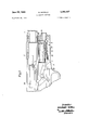
- FIG. 1 is partial section of the lifter and the cartridge magazine with the lifter in the condition of manual introduction of the cartridges linto the magazine;
- FIG. 2 is a section similar to FIGURE 1, but with the lifter in the cartridge locking condition;
- FIG. 3 is a section similar to FIGURE l, but in the condition of housing a cartridge on the lifter;
- FIG. 4 is a section similar to FIGURE l, but in the condition of positioning the cartridge in the barrel;
- FIGS. 5 and 6 are perspective views of the lifter in two different conditions. F
- an automatic shotgun is shown ICC having a barrel 1 integral with the breech 2 and which, when tiring has occurred, moves backwards with the latter and then returns into the normal position by means of a customary return spring. During the return movement, a fresh cartridge which is to be red enters the tiring chamber.
- a bore 4 which is extended into the stock of the shotgun and in which there is inserted a metallic tube 5 which constitutes the cartridge magazine with a cup 6 slidable therein and urged towards the right-hand side of the drawing by a helical spring 7 inserted in the tube 5 between the cup and the closed end of the magazine.
- the trigger-guard element 3 has a chamber 8 in front of the open end of the magazine, and opens downwardly to permit the introduction of the cartridges into the magazine.
- a lifter generally designated at 9 (see FIGS. 5 and 6) and substantially consisting in two elements.
- One element, designated 10, has a frontal plate 11 on the sides of which are fixed two arms 12 and 13 extending at right angles to the plate 11.
- the plate 11 has at the rear two shoulders 14 and 15, one on each side, having in their upper portion two holes 22 disposed in mutual coaxial alignment intended to receive a pin 16 (FIG. l) of a positioner 17 inserted in a tube 18 provided in the hand-guard rod 19 of the shotgun and continuously urged by a helical spring 20 disposed in the tube 18.
- the free ends of the two arms 12 and 13 each has a through hole 21 arranged coaxially aligned.
- the arm 12 has on its upper edge a semi-circular recess 23, the purpose of which will be explained hereinbelow.
- the other element, designated 24, is arcuate and has a cylindrical seat 25 suitable for housing a cartridge.
- a projection 26 carrying an outwardly projecting stud 27 which is intended to be normally housed in the semi-circular recess 23 of the element 1i).
- One end of the element 24 has a through hole (not shown in the figure) which serves to pivotally connect the said end to the free end of the arms 12 and 13 by means of a pin 28. In this way the element 10 is pivoted to the casing of the shotgun by means of the pin 16, whereas the element 24 is pivoted in the element 10 by the pin 28, and the two elements are thus pivotally movable in both directions.
- FIGS. 1 4 are views of subsequent steps of the movement ofthe lifter.
- FIG. l illustrates the position of the lifter 9 at the step of introducing the cartridge C manually into the attached magazine 5 which, as already stated, extends from the trigger-guard element 3 into the stock of the shotgun.
- the lifter 9 By pressing the lifter 9 towards the breech block 29, the lifter permits entry of the cartridge C into the magazine 5.
- the lifter 9 is automatically restored into the cartridge holding position by means of the positioner 17, which slides in the tube 18 and is urged continuously forward by the spring 20. This movement is repeated at each introduction of a cartridge until the magazine 5 is full.
- FIG. 2 illustrates the position of the lifter 9 at the cartridge blocking step in the magazine 5, maintained by the positioner 17.
- FIG. 3 illustrates the beginning of the step of loading the cartridge C into the barrel 1.
- This movement of the lifter 9 occurs after the expulsion of the fired cartridge and after the recoil has occurred, with the return into position of the breech-barrel 2-1.
- a suitable ⁇ ltasaasv' rotate downwardly about the pin 16, permitting the eartridge C, urged by the spring 7, to slide in the cylindrical seat 25 of the element 24 of the lifter 9 until it strikes against the plate 11.
- FIG, 4 illustrates the final step for the leading ot the cartridge C into the barrel l. Whilst the cartridge C is travelling the final millimetres of its travel in the seat 25 of the element 24 of the lifter 9, it squeezes a lug (not shown) which releases a lever 30 which rotates by the action of a bias-tensioned spring of the breech block 29, and in its rotation the lever 30 displaces the element 24 of the elevator by means of the stud 27 upwardly about its pivot 28 and transports the cartridge C into the position of introduction into the barrel l. Upon movement of the lever 30, the breech block 29 is released and urges the cartridge into the barrel, returns, the lever 30 into the position of abutment, and terminates with the closure of the weapon.
- a single barreled automatic shotgunsof the multipleshot or repeating type having a stock, a casing defining a tiring chamber supported on said stock, a trigger-guard mounted ou said stock adjacent said tiring chamber, and a cartridge-loading mechanism comprising a cartridge magazine having an open and a closed end disposed on the trigger-guard element with said closed end extending into the stock, and a lifter arranged at said open end of the magazine consisting in a first section pivoted adjacent one end to said casing and a second section pivoted to the opposite free end of said rst section such that said sections are operatively arranged for pivotal lifting movement effective to carry a cartridge placed on said second section into said firing chamber, said second section having a cylindrical surface forming a seat for said cartridge and a laterally projecting stud thereon which serves as a grip facilitating the raising of said sections through said pivotal lifting movement.
Description
June 25, 1968 G. BENELLI AUTOMATIC SHOTGUN 5 Sheets-Sheet l Filed May 25 1966 Inventor.- GIOVANM BENELU HTRSRNEYS G. BEN ELL;
AUTOMATIC SHOTGUN June 25, 1968 5 Sheets-Sheet 2 Filed May 26, 1966 /nventor GIOV/1N NI BENE LU Mem N .um
June 25, 1968 G. BENELLI AUTOMATIC SHOTGUN 5 Sheets-Sheet 3 Filed May 26. 1966 /nvenorf GloVANM BENELu 70mm/em ATTORNSYS June 25, 1968 G. BENELLI 3,389,487
AUTOMATIC SHOTGUN Filed May 26, 1966 5 Sheets-Sheet 4 Fig.
nvenor: Gaovmm Einem WMI: mi
June 25, 1968 G BENELU AUTOMAT I C SHOTGUN 5 Sheets-Sheet 5 Filed May 26, 1966 Inventor.
" Gsm/Anm Baum mem Anevs F ig.6
United States Patent O 3,339,487 AUTOMATIC SHOTGUN Giovanni Benelli, Pesaro, Italy, assgnor to S.A.S. F.lli
Benelli G.F. & C., Pesaro, Italy, a corporation of 5 Italy Filed May 26, 1966, Ser. No. 553,168 Claims priority, application Italy, Aug. 6, 1965, 17 ,802/ 65 1 Claim. (Cl. 42-17) ABSTRACT OF THE DISCLOSURE This invention relates to an automatic shotgun with a cartridge magazine in the stock, and to a cartridge feeder device for said shotgun.
Single barreled multiple-shot, or repeating, Shotguns are known, wherein the expulsion of the cartridge which has been tired, the introduction into the tiring chamber of the cartridges to be fired, and the loading or cocking of the percussion elements, are effected automatically by the reaction of the gases (recoil) which causes the barrel to move backwards integrally with the loading and tiring mechanism.
Such Shotguns generally have the cartridge magazine in the initial section of the barrel and this leads to an unbalance of the weapon, because it is made heavier by the weight ofthe said cartridges at the front.
It is the object of this invention to provide a shotgun of the aforesaid type which is more highly balanced by means of a special arrangement of the cartridge magazine in the shotgun.
Another object of the present invention is to provide a device to feed the cartridges into the tiring chamber which will permit introduction of the cartridges into the magazine in a simple and reliable manner. 5
More particularly, the automatic shotgun according to the present invention is characterised in that it comprises a cartridge magazine arranged on the triggerguard element and extended into the stock, and a lifter arranged at the end of the magazine and consisting in a sec- 50 tion pivoted to the casing of the shotgun and a section pivoted to the iirst section so that the two sections tilt in both directions to permit the introduction of the cartridge into the magazine and to carry the cartridge which is to be tired from time to time into the tiring chamber. 55
The invention will now be described in further detail with reference to a preferred embodiment thereof, given purely as an example and therefore in no limiting sense, and illustrated in the accompanying drawings, wherein:
FIG. 1 is partial section of the lifter and the cartridge magazine with the lifter in the condition of manual introduction of the cartridges linto the magazine;
FIG. 2 is a section similar to FIGURE 1, but with the lifter in the cartridge locking condition;
FIG. 3 is a section similar to FIGURE l, but in the condition of housing a cartridge on the lifter;
FIG. 4 is a section similar to FIGURE l, but in the condition of positioning the cartridge in the barrel;
FIGS. 5 and 6 are perspective views of the lifter in two different conditions. F
Referring now to the drawings, and more particularly to FIGS. 1, 5 and 6, an automatic shotgun is shown ICC having a barrel 1 integral with the breech 2 and which, when tiring has occurred, moves backwards with the latter and then returns into the normal position by means of a customary return spring. During the return movement, a fresh cartridge which is to be red enters the tiring chamber.
In the trigger-guard element 3 there is provided a bore 4 which is extended into the stock of the shotgun and in which there is inserted a metallic tube 5 which constitutes the cartridge magazine with a cup 6 slidable therein and urged towards the right-hand side of the drawing by a helical spring 7 inserted in the tube 5 between the cup and the closed end of the magazine. The trigger-guard element 3 has a chamber 8 in front of the open end of the magazine, and opens downwardly to permit the introduction of the cartridges into the magazine.
In the chamber 8 is disposed a lifter generally designated at 9 (see FIGS. 5 and 6) and substantially consisting in two elements. One element, designated 10, has a frontal plate 11 on the sides of which are fixed two arms 12 and 13 extending at right angles to the plate 11. The plate 11 has at the rear two shoulders 14 and 15, one on each side, having in their upper portion two holes 22 disposed in mutual coaxial alignment intended to receive a pin 16 (FIG. l) of a positioner 17 inserted in a tube 18 provided in the hand-guard rod 19 of the shotgun and continuously urged by a helical spring 20 disposed in the tube 18.
The free ends of the two arms 12 and 13 each has a through hole 21 arranged coaxially aligned. The arm 12 has on its upper edge a semi-circular recess 23, the purpose of which will be explained hereinbelow.
The other element, designated 24, is arcuate and has a cylindrical seat 25 suitable for housing a cartridge. On one side of the element 24 there is a projection 26 carrying an outwardly projecting stud 27 which is intended to be normally housed in the semi-circular recess 23 of the element 1i). One end of the element 24 has a through hole (not shown in the figure) which serves to pivotally connect the said end to the free end of the arms 12 and 13 by means of a pin 28. In this way the element 10 is pivoted to the casing of the shotgun by means of the pin 16, whereas the element 24 is pivoted in the element 10 by the pin 28, and the two elements are thus pivotally movable in both directions.
The operation of the device will now be described with reference to FIGS. 1 4, which are views of subsequent steps of the movement ofthe lifter.
FIG. l illustrates the position of the lifter 9 at the step of introducing the cartridge C manually into the attached magazine 5 which, as already stated, extends from the trigger-guard element 3 into the stock of the shotgun.
By pressing the lifter 9 towards the breech block 29, the lifter permits entry of the cartridge C into the magazine 5.
As soon as the cartridge C is fully introduced into the magazine 5, the lifter 9 is automatically restored into the cartridge holding position by means of the positioner 17, which slides in the tube 18 and is urged continuously forward by the spring 20. This movement is repeated at each introduction of a cartridge until the magazine 5 is full.
FIG. 2 illustrates the position of the lifter 9 at the cartridge blocking step in the magazine 5, maintained by the positioner 17.
FIG. 3 illustrates the beginning of the step of loading the cartridge C into the barrel 1. This movement of the lifter 9 occurs after the expulsion of the fired cartridge and after the recoil has occurred, with the return into position of the breech-barrel 2-1. As soon as the breechbarrel unit returns into the blocking position, a suitable `ltasaasv' rotate downwardly about the pin 16, permitting the eartridge C, urged by the spring 7, to slide in the cylindrical seat 25 of the element 24 of the lifter 9 until it strikes against the plate 11.
FIG, 4 illustrates the final step for the leading ot the cartridge C into the barrel l. Whilst the cartridge C is travelling the final millimetres of its travel in the seat 25 of the element 24 of the lifter 9, it squeezes a lug (not shown) which releases a lever 30 which rotates by the action of a bias-tensioned spring of the breech block 29, and in its rotation the lever 30 displaces the element 24 of the elevator by means of the stud 27 upwardly about its pivot 28 and transports the cartridge C into the position of introduction into the barrel l. Upon movement of the lever 30, the breech block 29 is released and urges the cartridge into the barrel, returns, the lever 30 into the position of abutment, and terminates with the closure of the weapon.
At this point the weapon is ready for tiring. Although only one embodiment of the invention has been illustrated, it is obvious that a number of changes may be made therein without departing from the scope of the invention.
I claim:
l. A single barreled automatic shotgunsof the multipleshot or repeating type having a stock, a casing defining a tiring chamber supported on said stock, a trigger-guard mounted ou said stock adjacent said tiring chamber, and a cartridge-loading mechanism comprising a cartridge magazine having an open and a closed end disposed on the trigger-guard element with said closed end extending into the stock, and a lifter arranged at said open end of the magazine consisting in a first section pivoted adjacent one end to said casing and a second section pivoted to the opposite free end of said rst section such that said sections are operatively arranged for pivotal lifting movement effective to carry a cartridge placed on said second section into said firing chamber, said second section having a cylindrical surface forming a seat for said cartridge and a laterally projecting stud thereon which serves as a grip facilitating the raising of said sections through said pivotal lifting movement.
References Cited llJNITED STATES PATENTS 272.636 `M1883 Boch 42-17 Il,l90,352 "il/1916 Winks 42-17 L27/0,408 `ll/l942 Burton 42-17 lBENJAMIN A. BORCHELT, Primary Examiner.
Applications Claiming Priority (1)
| Application Number | Priority Date | Filing Date | Title |
|---|---|---|---|
| IT1780265 | 1965-08-06 |
Publications (1)
| Publication Number | Publication Date |
|---|---|
| US3389487A true US3389487A (en) | 1968-06-25 |
Family
ID=11150947
Family Applications (1)
| Application Number | Title | Priority Date | Filing Date |
|---|---|---|---|
| US553168A Expired - Lifetime US3389487A (en) | 1965-08-06 | 1966-05-26 | Automatic shotgun |
Country Status (4)
| Country | Link |
|---|---|
| US (1) | US3389487A (en) |
| BE (1) | BE674177A (en) |
| FR (1) | FR1456367A (en) |
| GB (1) | GB1136604A (en) |
Cited By (3)
| Publication number | Priority date | Publication date | Assignee | Title |
|---|---|---|---|---|
| US6347569B1 (en) * | 2000-07-24 | 2002-02-19 | Lawrence V Butler | Semi-automatic gas-operated shotgun |
| US6612062B1 (en) | 2001-02-20 | 2003-09-02 | R.A. Brands, L.L.C. | Carrier locking device |
| US9417019B2 (en) | 2012-08-24 | 2016-08-16 | Ra Brands, L.L.C. | Fire control for auto-loading shotgun |
Citations (3)
| Publication number | Priority date | Publication date | Assignee | Title |
|---|---|---|---|---|
| US272636A (en) * | 1883-02-20 | Magazine gun | ||
| US1190352A (en) * | 1914-04-07 | 1916-07-11 | John O Winks | Automatic firearm. |
| US2270408A (en) * | 1939-04-13 | 1942-01-20 | Western Cartridge Co | Cartridge-detent mechanism for repeating firearms |
-
1965
- 1965-12-02 FR FR46659A patent/FR1456367A/en not_active Expired
- 1965-12-21 GB GB54109/65A patent/GB1136604A/en not_active Expired
- 1965-12-22 BE BE674177D patent/BE674177A/xx unknown
-
1966
- 1966-05-26 US US553168A patent/US3389487A/en not_active Expired - Lifetime
Patent Citations (3)
| Publication number | Priority date | Publication date | Assignee | Title |
|---|---|---|---|---|
| US272636A (en) * | 1883-02-20 | Magazine gun | ||
| US1190352A (en) * | 1914-04-07 | 1916-07-11 | John O Winks | Automatic firearm. |
| US2270408A (en) * | 1939-04-13 | 1942-01-20 | Western Cartridge Co | Cartridge-detent mechanism for repeating firearms |
Cited By (4)
| Publication number | Priority date | Publication date | Assignee | Title |
|---|---|---|---|---|
| US6347569B1 (en) * | 2000-07-24 | 2002-02-19 | Lawrence V Butler | Semi-automatic gas-operated shotgun |
| US6612062B1 (en) | 2001-02-20 | 2003-09-02 | R.A. Brands, L.L.C. | Carrier locking device |
| US6742298B1 (en) | 2001-02-20 | 2004-06-01 | Ra Brands, Llc | Carrier locking device |
| US9417019B2 (en) | 2012-08-24 | 2016-08-16 | Ra Brands, L.L.C. | Fire control for auto-loading shotgun |
Also Published As
| Publication number | Publication date |
|---|---|
| BE674177A (en) | 1966-04-15 |
| GB1136604A (en) | 1968-12-11 |
| FR1456367A (en) | 1966-10-21 |
Similar Documents
| Publication | Publication Date | Title |
|---|---|---|
| US4061074A (en) | Ammunition feed mechanism | |
| US2554116A (en) | Gas operated gun | |
| US3736839A (en) | Dual mode shotgun | |
| GB1167536A (en) | Improvements in Automatic Guns | |
| US2675638A (en) | Fire control for firearms | |
| US3442173A (en) | Combined rifle and grenade launcher weapon selectively fired by a single trigger | |
| US2744448A (en) | Automatic pistol | |
| US2336146A (en) | Firearm | |
| US2401903A (en) | Repeating firearm | |
| US580924A (en) | Firearm | |
| GB1229025A (en) | ||
| US4679486A (en) | Combination gun with repeater mechanism | |
| US2448081A (en) | Automatic ammunition feed for firearms | |
| GB616595A (en) | Improvements in or relating to automatic guns | |
| US3389487A (en) | Automatic shotgun | |
| US3680433A (en) | Semi-automatic shotgun having rotary and sliding breech block | |
| US3355988A (en) | Laterally sliding breechblock for loading a large caliber gun | |
| US1651128A (en) | Automatic gun | |
| US3866516A (en) | Semi-automatic piston employing a pivotally, slideable member | |
| US2922240A (en) | Firearm with interengageable breech block and slide block and double action bars | |
| US3044203A (en) | Firearm with reciprocable bolt having transverse movement | |
| US486273A (en) | Breegh-loadslsfq firearm | |
| US3759135A (en) | Semi-automatic shotgun | |
| US3172222A (en) | Self-locking carrier | |
| US1395460A (en) | Double-barreled gun |