US3441289A - Drop out front cross member - Google Patents
Drop out front cross member Download PDFInfo
- Publication number
- US3441289A US3441289A US577004A US3441289DA US3441289A US 3441289 A US3441289 A US 3441289A US 577004 A US577004 A US 577004A US 3441289D A US3441289D A US 3441289DA US 3441289 A US3441289 A US 3441289A
- Authority
- US
- United States
- Prior art keywords
- isolator
- cross member
- socket
- side rail
- mounting
- Prior art date
- Legal status (The legal status is an assumption and is not a legal conclusion. Google has not performed a legal analysis and makes no representation as to the accuracy of the status listed.)
- Expired - Lifetime
Links
Images
Classifications
-
- B—PERFORMING OPERATIONS; TRANSPORTING
- B60—VEHICLES IN GENERAL
- B60G—VEHICLE SUSPENSION ARRANGEMENTS
- B60G99/00—Subject matter not provided for in other groups of this subclass
-
- B—PERFORMING OPERATIONS; TRANSPORTING
- B62—LAND VEHICLES FOR TRAVELLING OTHERWISE THAN ON RAILS
- B62D—MOTOR VEHICLES; TRAILERS
- B62D21/00—Understructures, i.e. chassis frame on which a vehicle body may be mounted
- B62D21/11—Understructures, i.e. chassis frame on which a vehicle body may be mounted with resilient means for suspension, e.g. of wheels or engine; sub-frames for mounting engine or suspensions
Definitions
- This invention relates to a front suspension system for a motor vehicle. More particularly, it relates to a front suspension system especially designed to prevent noise and vvibration lgenerated at the front wheel assemblies from entering the body structure.
- the front suspension system of the invention is especially suited to, but not limited to, a body structure of the unitized type wherein no separate frame is employed.
- a more specific object is to provide a front suspension system which is especially suitable for use with a motor vehicle having a unitized body.
- Yet another object is to provide a front suspension effective to absorb noises and vibrations generated at the wheel assemblies and prevent their transmittal to the body structure.
- a more specific object is to provide a front end suspension for use with a motor vehicle having a unitized body structure wherein means are provided to prevent or substantially reduce telegraphing of road noises and vibrations generated at the wheel assemblies to the passenger compartment through the unitized body structure.
- the front end suspension of the invention includes a cross member which extends transversely of the body side rail members adjacent the forward end of the motor vehicle and to the opposite ends of which the left and right front wheel assemblies are pivotally mounted.
- means are provided to mount each end of the cross member to the adjacent side rail member at at least two longitudinally spaced points along that rail member and an isolator member of resilient material is interposed between the cross member and the adjacent side rail at each of the mounting points.
- This arrangement precludes direct metal to metal contact between the cross members and the side rail members and 3,441,289 Patented Apr. 29, 1 969 ice serves to cushion the body structure against road shocks and noise generated at the wheel assemblies.
- each of the resilient isolator members is generally tubular in form and the aforesaid mounting means for each isolator member comprises a pin passing through the related isolator member and a socket receiving the isolator member.
- the longitudinal axis of each of the mounting pins, and therefore of the tubular isolator member received thereover, is generally parallel to the longitudinal axis of the vehicle so as to allow a controlled amount of fore and aft movement of the suspension cross member relative to the body structure.
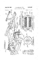
- FIG. 1 is a perspective view of a portion of a motor vehicle having a front end suspension system according to the invention
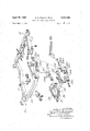
- FIG. 2 is an exploded perspective view similar to FIG. l but with the fro-nt wheel assemblies omitted;
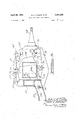
- FIG. 3 is a cross sectional view taken on kline 3-3 of FIG. l;
- FIG. 4 is a fragmentary cross sectional view showing details of one of the mounting means for the front suspension cross member.
- FIG. 5 is a cross sectional view taken on line 5--5 of FIG. 4.
- FIGS. 1 and 2 disclose a sub-frame assembly 10 of box form comprising a right side rail 12, left side rail 14, front cross member 16, and rear cross member 18.
- Subframe assembly 10 is adapted to be bolted to a body of unitized construction to form the forestructure of that body.
- the invention is described herein with particular reference to a unitized body having a subframe forestructure, it will be understood that the invention is not limited to such a body structure but is also applicable to fully unitized body structures or to body structures employing separate, full length, frames.
- the suspension system of the invention includes a special suspension cross member 20 extending transversely between side rails 12 and 14 adjacent the forward end of the Vehicle.
- ⁇ Cross member 20 is seen in assembled relation to sub-frame 10 in FIG. 1 and in exploded relation to sub-frame 10 in FIG. 2.
- Cross member 20 is a composite welded structure comprising a central beam mem-ber 22 of box cross section and left and right tower structures 24 welded to the opposite ends of central beam member 22.
- Each tower structure 24 comprises a horizontally disposed channel member 26 (FIG. 3) welded to a vertical plate 28 to form therewith a box structure which is Welded to the respective end of the beam member 22.
- Cross member 20 further includes left and right diagonal braces 30 which are welded at one end to the central beam member 22 and extend diagonally forward therefrom to pass immediately -beneath the forward end of the related tower structure 24. Each brace 30 is welded to the respective tower structure 24 at the interface therebetween.
- each diagonal brace 30 outboard of the related tower structure 24 is configured to define a pair of longitudinally spaced, vertically extending walls 30a and 30b having longitudinally aligned apertures therein.
- the rearward portion of each tower structure 24 is similarly conligured to deline a pair of spaced walls 24a and 24b havin-g longitudinally aligned apertures therein.
- the upper portion of each tower structure plate 28 is selectively recessed to provide an outwardly facing mounting surface 31.
- Cross member 20 further includes left and right brackets or cradles 32 which present angled, opposed surfaces 33 on which the front end of the engine (not shown) is cradled.
- the vehicle steering gear (not shown) is also carried by cross member 20.
- a socket member 34 is bolted to the underside of each side rail 12, 14 adjacent the forward end thereof and a socket member 36 is bolted to the underface of each side rail 12, 14 in rearwardly spaced relation to the related socket member 34.
- Each of the socket members 34, 36 includes a base portion 34a, 36a by which the socket member is secured to the overlying side rail and a tubular portion 34b, 36b which is adapted to be received between the spaced walls 30a, 30b and 24a, 24b, respectively.
- the suspension cross member 20 is connected to side rails 12 and 14 by resilient isolator members 38, best seen in FIGS. 4 and 5.
- Each isolator member 38 is formed of a suitable resilient material, such for example as hard rubber, and is generally tubular in form.
- An outer metallic sleeve or shell 38a forms the external periphery of each isolator member and an inner sleeve 3811 forms the internal periphery of each isolator member.
- Each isolator member further includes a resilient flange portion 38C extending radially outwardly from the cylindrical outer periphery of the main body portion at one end of the isolator member.
- each isolator member is chamfered at 38d; each flange portion is also selectively cut away at 38e to divide the radially outer portion of the ange portion into a plurality of circumferentially spaced segrnents.
- each isolator member is provided with a flange portion 38)c to provide a metallic backing for resilient flange portion 38e.
- the forward isolator members 38 are inserted with a press lit into the related socket 34b to press ilange portion 38e ⁇ against the forward face of socket portion 34b.
- Each forward isolator member is further received between the spaced walls 30a, 30b provided by the related diagonal brace 30. Walls 30a, 30b are squeezed tightly against the opposite ends of the isolator member by a pin or bolt 40 passing through the aligned apertures in walls 30a, 30b and through the inner sleeve 38b for engagement by a nut 42.
- Each rearward isolator member is inserted into rearward socket portion 36b to press ange portion 38C against the rearward face of socket portion 36b.
- Each rearward isolator member is positioned between spaced walls 24a, 24b provided by the related tower structure 24. Walls 24a, 24b are thereafter squeezed together in clamping relation to the isolator member by a pin or bolt 44 passing through the aligned apertures in walls 24a, 24b and through central sleeve 38b for engagement by a nut 46.
- cross member 20 is thus rubber mounted at each end to the adjacent side rail at two longitudinally spaced points along that rail.
- This mounting arrangement precludes metal to metal contact between cross member 20 and side rails 12, 14 so that any noise or vibration generated in cross member 20 will be largely absorbed by the resilient material comprising isolator members 38.
- forward or rearward movement of the cross member 20 relative to the sub-frame assembly is limited by the engagement of socket portions 34b by the llange portions 38d of the forward isolator members and the engagement of socket portions 36b by the flange portions 38d of the rear isolator members.
- a controlled amount of relative forward movement is permitted however by the yielding compression of flange portions 38e of the rear isolator members between socket portions 36b and walls 24b and a controlled amount of relative rearward movement is permitted by the yielding compression of flange portions 38e of the front isolator members between socket portions 34b and walls 30a.
- the chamfer 38d on the flange portion of each isolator member allows that portion to yield readily to relatively small forces generated at the wheel asesmblies, whereby to absorb these forces and preclude their transmittal to the body structure.
- the flange portions When larger forces are generated at the wheel assemblies, however, the flange portions quickly initially yield or deflect to take up the void created by the chamfer, whereafter the yield rate is determined by the compression of the rubber of the flange portions between the confronting faces of the socket portions 34b, 36h and the walls 30a, 24b.
- the yield rate of the isof lator member is initially relatively high, whereby to effectively absorb small shocks generated by minor irregularities in the road surface, whereafter the yield rate becomes significantly lower to avoid mushiness or excessive lost motion in the front end suspension.
- the amount and rate of relative fore and aft movement permitted may be selectively varied by varying the durometer of the material of the isolator member and/or by varying the size and/or shape of the chamfer 38d.
- Each wheel suspension assembly as best seen in FIG. 3, includes a bracket 52 secured in cantilever fashison to the mounting face 32 of the respective tower structure plate 28 by bolts 54; a pivot shaft 56 secured to bracket 52 by bolts 58 (FIG.
- each torsion bar is also hexagonal in cross section and passes through rear cross member 18 for receipt in a hexagonal socket 92 provided in a rear anchor cross member 93.
- Rear anchor member 93 is adapted to be bolted to rear cross member 18 with resilient isolator members 94 positioned therebetween to isolate the subframe 10 from noise and vibration transmitted from the wheel assemblies through the torsion bars. Further details of the manner in which the torsion bars are isolated from the sub-frame are disclosed in copending United States patent application Ser. No. 385,699 filed July 28, 1964 now Patent No. 3,288,487.
- suspension cross member 20 Since the wheel suspension assemblies are carried in their entirety by suspension cross member 20 and since cross member 20 is rubber isolated in the manner previously described from sub-frame 10, it will be seen that the sub-frame and therefore the passenger compartment are cushioned from noise and vibration generated at the wheel assemblies.
- Amotor vehicle comprising: (A) a body structure defining spacedvlon'gitudinal side rail members; (B) a front suspension assembly comprising (1) a cross memberextending traversely of said siderail members adjacent the forward end of said motor vehicle,
- (C) means mounting each end of said cross member to the adjacent side 4rail member at at' least two longitudinally spaced points along that rail;
- each said socket is carried by the related side rail member and (F) each said pair of mounting walls is defined by said cross member.
- a motor vehicle according to claim 1 wherein:
- each said tubular isolator element includes a ange portion at one end thereof
- each forward isolator element being positioned within the related socket with the flange portion thereof engaging the forward face of the socket, whereby to preclude rearward movement of said cross member relative to said body structure and (2) each rearward isolator element being positioned within the related socket with the ange portion thereof engaging the rearward face of the socket, whereby to preclude forward movement of said cross member relative to said body structure.
- each said socket is carried by the related side rail member
- each said pair of mounting walls is defined by said cross member.
- each said independent suspension means includes (l) a torsion bar extending generally longitudinally of the vehicle and having one end arranged to be rotated in response to movement of said wheel assemblies Arelative to said cross member;
- a resilient isolator element interposed between said anchor member and said body structure to allow fore and aft movement of said anchor member ⁇ and torsion bar relative to said body structure in response to fore and aft movement of said cross member relative to said side rails.
- a motor vehicle comprising:
- a front suspension assembly comprising (l) a cross member extending transversely of said side rail members adjacent the forward end of said motor vehicle,
- (C) means mounting each end of l'said cross member to the adjacent side rail member at at least two longitudinally spaced points along that rail,
- each such mounting means comprising (a) a generally tubular isolator member arranged with its longitudinal axis generally parallel to the longitudinal axis of the vehicle, v
- each isolator member including a flange portion at one end thereof with each forward isolator being positioned within the related socket with the flange portion thereof engaging the forward face of the socket a-n-d each rearward isolator being positioned within the related socket with the ange portion thereof engaging the rearward face of the socket, and
- a motor vehicle comprising:
- (C) means mounting each end of said cross member to the adjacent side rail member at at least two longitudinally spaced points along that rail;
- said cross member comprises (l) a central, transversely extending beam member
- each such end structure further includes mounting 'structure extending forwardly and rearwardly of saidl 7 8 cross beam member to respectively ⁇ dene forward erally cylindrical, longitudinally extending sockand rearward mounting points, as aforesaid, for interet positioned between said mounting rails and connection of said cross member and said side rails. receiving said isolator element therewithin.
- each said isolator element is generally tubular in 5 References Cited h d tr t r d t h f s d UNITED STATES PATENTS eac en s uc ure 1s con gu e a eac o a1 forward ⁇ and rearward mounting points to define a Xly 25g-151g? pair of longitudinally spaced generally vertical, con- 3068020 :l2/1962 Muue" 'tg 28O 106 ⁇ 5 frontmg mounting walls defining a pocket therebelo 3201142 8/1965 D teh.
- said mounting means at each mounting poi-nt fur- 3288487 11/1966 Bosley et al *T 28o-124 ther includes (l) a pin passing through longitudinally aligned BENJAMIN HERSH Primary Examlner' apertures in said mounting walls and through 15 L. DANIEL MORRIS, JR., Assistant Examiner. said isolator element 0r orient the isolator element with its central axis extending generally U-S Cl- X-R- longitudinally, and 296--28 (2) means on the related side rail defining a gen-
Description
Applications Claiming Priority (1)
| Application Number | Priority Date | Filing Date | Title |
|---|---|---|---|
| US57700466A | 1966-09-02 | 1966-09-02 |
Publications (1)
| Publication Number | Publication Date |
|---|---|
| US3441289A true US3441289A (en) | 1969-04-29 |
Family
ID=24306892
Family Applications (1)
| Application Number | Title | Priority Date | Filing Date |
|---|---|---|---|
| US577004A Expired - Lifetime US3441289A (en) | 1966-09-02 | 1966-09-02 | Drop out front cross member |
Country Status (1)
| Country | Link |
|---|---|
| US (1) | US3441289A (en) |
Cited By (15)
| Publication number | Priority date | Publication date | Assignee | Title |
|---|---|---|---|---|
| EP0182480A2 (en) * | 1984-11-15 | 1986-05-28 | Ford Motor Company Limited | Automotive suspension control arm |
| US4763948A (en) * | 1985-07-16 | 1988-08-16 | Mazda Motor Corporation | Automobile front body construction |
| US5641181A (en) * | 1995-03-23 | 1997-06-24 | Ford Motor Company | Cross member for a vehicle having rack and pinion steering |
| DE19612885A1 (en) * | 1996-03-30 | 1997-10-02 | Porsche Ag | Support component for drive assembly of motor vehicle |
| US5971412A (en) * | 1996-06-15 | 1999-10-26 | Daimler Chryler A.G. | Support frame for connecting the wheel support elements of a vehicle to a vehicle body |
| US6120059A (en) * | 1997-06-04 | 2000-09-19 | Dana Corporation | Vehicle frame assembly |
| US6149197A (en) * | 1997-06-06 | 2000-11-21 | Suzuki Motor Corporation | Structure of front body of automobiles |
| US6398262B1 (en) * | 2000-09-26 | 2002-06-04 | Dana Corporation | Modular subframe assembly for a motor vehicle |
| US6516914B1 (en) * | 1993-04-14 | 2003-02-11 | Oshkosh Truck Corporation | Integrated vehicle suspension, axle and frame assembly |
| US20070221430A1 (en) * | 2006-03-21 | 2007-09-27 | Allison Kenneth M Sr | Modular automobile system and method |
| US7559403B2 (en) | 2006-04-05 | 2009-07-14 | Schmitz Geoffrey W | Modular, central frame, offset, dual control arm independent suspension and suspension retrofit |
| DE102008007092A1 (en) * | 2008-01-31 | 2009-08-06 | Zf Friedrichshafen Ag | Elastomeric bush bearing for supporting parts of chassis in vehicle construction, has elastomeric buffer pre-stressed between adjoined geometry of attachment and outer contour of outer sleeve, and provided in subsection of eye-shaped recess |
| US20110068551A1 (en) * | 2008-05-26 | 2011-03-24 | Ksm Castings Gmbh | Axle bracket for motor vehicles |
| US20140091599A1 (en) * | 2012-09-28 | 2014-04-03 | Ford Motor Company | Front end assembly for vehicle chassis |
| USD749466S1 (en) * | 2014-09-08 | 2016-02-16 | Dennis Michael Nosworthy | Passenger vehicle chassis rear crossmember |
Citations (5)
| Publication number | Priority date | Publication date | Assignee | Title |
|---|---|---|---|---|
| US2636750A (en) * | 1950-12-12 | 1953-04-28 | Budd Co | Crossbeam attachment for automobiles |
| US2939720A (en) * | 1957-02-12 | 1960-06-07 | Gen Motors Corp | Road noise isolation means for a motor vehicle suspension support |
| US3068020A (en) * | 1958-08-20 | 1962-12-11 | Daimler Benz Ag | Wheel suspension for vehicles |
| US3201142A (en) * | 1962-11-22 | 1965-08-17 | Applic Ind Commerciales Et Imm | Automobile vehicle suspension |
| US3288487A (en) * | 1964-07-28 | 1966-11-29 | Chrysler Corp | Torsion bar wheel suspension |
-
1966
- 1966-09-02 US US577004A patent/US3441289A/en not_active Expired - Lifetime
Patent Citations (5)
| Publication number | Priority date | Publication date | Assignee | Title |
|---|---|---|---|---|
| US2636750A (en) * | 1950-12-12 | 1953-04-28 | Budd Co | Crossbeam attachment for automobiles |
| US2939720A (en) * | 1957-02-12 | 1960-06-07 | Gen Motors Corp | Road noise isolation means for a motor vehicle suspension support |
| US3068020A (en) * | 1958-08-20 | 1962-12-11 | Daimler Benz Ag | Wheel suspension for vehicles |
| US3201142A (en) * | 1962-11-22 | 1965-08-17 | Applic Ind Commerciales Et Imm | Automobile vehicle suspension |
| US3288487A (en) * | 1964-07-28 | 1966-11-29 | Chrysler Corp | Torsion bar wheel suspension |
Cited By (19)
| Publication number | Priority date | Publication date | Assignee | Title |
|---|---|---|---|---|
| EP0182480A2 (en) * | 1984-11-15 | 1986-05-28 | Ford Motor Company Limited | Automotive suspension control arm |
| EP0182480A3 (en) * | 1984-11-15 | 1987-08-19 | Ford Motor Company Limited | Automotive suspension control arm |
| US4763948A (en) * | 1985-07-16 | 1988-08-16 | Mazda Motor Corporation | Automobile front body construction |
| US6516914B1 (en) * | 1993-04-14 | 2003-02-11 | Oshkosh Truck Corporation | Integrated vehicle suspension, axle and frame assembly |
| US5641181A (en) * | 1995-03-23 | 1997-06-24 | Ford Motor Company | Cross member for a vehicle having rack and pinion steering |
| DE19612885C2 (en) * | 1996-03-30 | 2001-09-06 | Porsche Ag | Carrying device |
| DE19612885A1 (en) * | 1996-03-30 | 1997-10-02 | Porsche Ag | Support component for drive assembly of motor vehicle |
| US5971412A (en) * | 1996-06-15 | 1999-10-26 | Daimler Chryler A.G. | Support frame for connecting the wheel support elements of a vehicle to a vehicle body |
| US6120059A (en) * | 1997-06-04 | 2000-09-19 | Dana Corporation | Vehicle frame assembly |
| US6149197A (en) * | 1997-06-06 | 2000-11-21 | Suzuki Motor Corporation | Structure of front body of automobiles |
| US6398262B1 (en) * | 2000-09-26 | 2002-06-04 | Dana Corporation | Modular subframe assembly for a motor vehicle |
| US20070221430A1 (en) * | 2006-03-21 | 2007-09-27 | Allison Kenneth M Sr | Modular automobile system and method |
| US7559403B2 (en) | 2006-04-05 | 2009-07-14 | Schmitz Geoffrey W | Modular, central frame, offset, dual control arm independent suspension and suspension retrofit |
| DE102008007092A1 (en) * | 2008-01-31 | 2009-08-06 | Zf Friedrichshafen Ag | Elastomeric bush bearing for supporting parts of chassis in vehicle construction, has elastomeric buffer pre-stressed between adjoined geometry of attachment and outer contour of outer sleeve, and provided in subsection of eye-shaped recess |
| US20110068551A1 (en) * | 2008-05-26 | 2011-03-24 | Ksm Castings Gmbh | Axle bracket for motor vehicles |
| US8684382B2 (en) * | 2008-05-26 | 2014-04-01 | Ksm Castings Group Gmbh | Axle bracket for motor vehicles |
| US20140091599A1 (en) * | 2012-09-28 | 2014-04-03 | Ford Motor Company | Front end assembly for vehicle chassis |
| US8876132B2 (en) * | 2012-09-28 | 2014-11-04 | Ford Global Technologies, Llc | Front end assembly for vehicle chassis |
| USD749466S1 (en) * | 2014-09-08 | 2016-02-16 | Dennis Michael Nosworthy | Passenger vehicle chassis rear crossmember |
Similar Documents
| Publication | Publication Date | Title |
|---|---|---|
| US3441289A (en) | Drop out front cross member | |
| US3913696A (en) | Chassis construction for a motor vehicle | |
| US2809851A (en) | Fifth wheel coupler mounting | |
| US4406474A (en) | Vehicle fender attachment and support structure | |
| US3520550A (en) | Energy absorbing structure for a motor vehicle | |
| US2751992A (en) | Unit power plant and axle unit suspension in motor vehicles | |
| US4501436A (en) | Supporting assembly for a suspension | |
| US4046415A (en) | Body mount system for a motor vehicle | |
| US3209851A (en) | Suspension system and engine mounting arrangement for motor vehicles | |
| US2564888A (en) | Cab mounting for motor vehicles | |
| US4097057A (en) | Independent suspension system | |
| US2715041A (en) | Shock absorbing and suspension means for vehicle bodies | |
| US4257623A (en) | Supporting structure for a suspension member for a vehicle | |
| US3817556A (en) | Motorcycle trailer | |
| US4451054A (en) | Vehicle suspension system | |
| US2322890A (en) | Vehicle wheel suspension | |
| US3177963A (en) | Vehicle suspension system | |
| US2480526A (en) | Vehicle spring suspension | |
| US3512800A (en) | Suspension of an auxiliary frame at the main frame of a vehicle,especially of a motor vehicle | |
| US3178202A (en) | Vehicle wheel suspension | |
| US3119628A (en) | Mounting of an auxiliary frame in vehicles | |
| US6095563A (en) | Pocketed four-link front suspension | |
| US3386752A (en) | Vehicle suspension system having torsion spring | |
| JP3129124B2 (en) | Suspension device | |
| US3288487A (en) | Torsion bar wheel suspension |
Legal Events
| Date | Code | Title | Description |
|---|---|---|---|
| AS | Assignment |
Owner name: FIDELITY UNION TRUST COMPANY, TRUSTEE,NEW JERSEY Free format text: MORTGAGE;ASSIGNOR:CHRYSLER CORPORATION;REEL/FRAME:003832/0358 Effective date: 19810209 Owner name: FIDELITY UNION TRUST COMPANY, 765 BROAD ST., NEWAR Free format text: MORTGAGE;ASSIGNOR:CHRYSLER CORPORATION;REEL/FRAME:003832/0358 Effective date: 19810209 |
|
| AS | Assignment |
Owner name: CHRYSLER CORPORATION, HIGHLAND PARK, MI 12000 LYNN Free format text: ASSIGNORS HEREBY REASSIGN, TRANSFER AND RELINQUISH THEIR ENTIRE INTEREST UNDER SAID INVENTIONS AND RELEASE THEIR SECURITY INTEREST.;ASSIGNORS:FIDELITY UNION BANK;ARNEBECK, WILLIAM, INDIVIDUAL TRUSTEE;REEL/FRAME:004063/0604 Effective date: 19820217 |
|
| AS | Assignment |
Owner name: CHRYSLER CORPORATION Free format text: PARTES REASSIGN, TRANSFER AND RELINQUISH THEIR ENTIRE INTEREST UNDER SAID PATENTS ALSO RELEASE THEIR SECURITY INTEREST.;ASSIGNOR:MANUFACTURERS NATIONAL BANK OF DETROIL (CORPORATE TRUSTEE) AND BLACK DONALD E., (INDIVIDUAL TRUSTEE);REEL/FRAME:004355/0154 Effective date: 19840905 |