US3476029A - Electrochromic shutter system - Google Patents
Electrochromic shutter system Download PDFInfo
- Publication number
- US3476029A US3476029A US661100A US3476029DA US3476029A US 3476029 A US3476029 A US 3476029A US 661100 A US661100 A US 661100A US 3476029D A US3476029D A US 3476029DA US 3476029 A US3476029 A US 3476029A
- Authority
- US
- United States
- Prior art keywords
- cell
- electrochromic
- zone
- exposure
- lens
- Prior art date
- Legal status (The legal status is an assumption and is not a legal conclusion. Google has not performed a legal analysis and makes no representation as to the accuracy of the status listed.)
- Expired - Lifetime
Links
Images

Classifications
-
- G—PHYSICS
- G02—OPTICS
- G02F—OPTICAL DEVICES OR ARRANGEMENTS FOR THE CONTROL OF LIGHT BY MODIFICATION OF THE OPTICAL PROPERTIES OF THE MEDIA OF THE ELEMENTS INVOLVED THEREIN; NON-LINEAR OPTICS; FREQUENCY-CHANGING OF LIGHT; OPTICAL LOGIC ELEMENTS; OPTICAL ANALOGUE/DIGITAL CONVERTERS
- G02F1/00—Devices or arrangements for the control of the intensity, colour, phase, polarisation or direction of light arriving from an independent light source, e.g. switching, gating or modulating; Non-linear optics
- G02F1/01—Devices or arrangements for the control of the intensity, colour, phase, polarisation or direction of light arriving from an independent light source, e.g. switching, gating or modulating; Non-linear optics for the control of the intensity, phase, polarisation or colour
- G02F1/17—Devices or arrangements for the control of the intensity, colour, phase, polarisation or direction of light arriving from an independent light source, e.g. switching, gating or modulating; Non-linear optics for the control of the intensity, phase, polarisation or colour based on variable-absorption elements not provided for in groups G02F1/015 - G02F1/169
- G02F1/172—Devices or arrangements for the control of the intensity, colour, phase, polarisation or direction of light arriving from an independent light source, e.g. switching, gating or modulating; Non-linear optics for the control of the intensity, phase, polarisation or colour based on variable-absorption elements not provided for in groups G02F1/015 - G02F1/169 based on a suspension of orientable dipolar particles, e.g. suspended particles displays
-
- G—PHYSICS
- G03—PHOTOGRAPHY; CINEMATOGRAPHY; ANALOGOUS TECHNIQUES USING WAVES OTHER THAN OPTICAL WAVES; ELECTROGRAPHY; HOLOGRAPHY
- G03B—APPARATUS OR ARRANGEMENTS FOR TAKING PHOTOGRAPHS OR FOR PROJECTING OR VIEWING THEM; APPARATUS OR ARRANGEMENTS EMPLOYING ANALOGOUS TECHNIQUES USING WAVES OTHER THAN OPTICAL WAVES; ACCESSORIES THEREFOR
- G03B9/00—Exposure-making shutters; Diaphragms
- G03B9/08—Shutters
Definitions
- a camera shutter system uses a normally opaque electrochromic cell and a mechanical light blocking device in series across the cameras light path and arranged so that full opening of the light blocking device closes a switch to electrically energize the cell.
- Such energization opens the cell to light and is maintained for a preselected interval for a photographic exposure. After the energiza tion is stopped, the cell relaxes to its opaque condition, and the mechanical device returns to its light blocking position.
- the light blocking device can be a variety of movable mechanical structures including a simple mechanical shutter of fixed opening period with the electrochromic cell energized upon full opening of the shutter.
- the cell and the light blocking device can be arranged in front of the lens, between elements of the lens, behind the lens, or ahead of the focal plane.
- the cell can be formed with several pairs of electrodes arranged as desired for photographic effects. Multiple electrode arrangements include concentric electrodes for a variable aperture cell and parallel zone electrodes that are variably energized for a focal plane cell.
- This invention relates to a general chromic camera shutter system.
- Electrochromic cells are generally known and have been used for goggles and variable density panels. Also, it has been suggested that such cells be used as camera shutters, but for various reasons they have not proved practically effective as suggested.
- the objects of this invention include, without limita tion, the following:
- the inventive shutter system includes an electrochromic cell and a mechanical light blocking de vice arranged in series across the light path of a camera.
- the protection afforded by a lens cap or dark slide is combined with the speed, versatility, simplicity, and
- electrochromic cell or more simply cell refers to .a liquid suspension of oblong particles between substantial- 1y transparent plates," the particles being normally randomly oriented making the suspension opaque to light, but the particles being'orientable in an electric field to align their major axes with the field for opening the cell to light.
- Such cells can be made of a liquid suspension of submicroscopic particles of various lengths that act as dipoles aligning with a high frequency electric field passed between the plates.
- Transparent electrodes are formed on each plate to apply high frequency energization across the liquid suspension.
- a variety of liquids, particle materials and sizes, plate"'materials, electrode material and arrangements, frequencies, voltages, etc. are possible for such electrochromic cells.
- electrochromic cell included within the meaning of such term in this application is a liquid suspension of needle-like magnetic bodies normally randomly oriented to make the suspension opaque, but capable of being oriented with an electro-rnagnetic field to" open the cell to light.
- electrochromic cell capable of changing their optical density in response to an electric field.
- Electrochromic cells 1" adaptable to the invention are presently marketed under, the brand name of Varad by the Marx Polarized Corporation of Whitestone, N.Y.
- electrochrom ells When electrochrom ells are referred to in the specification and claims as d to light, this means either random orientation of the suspended particles under the influence of Brownian movement, or orientation of the particles transverse to the light transmission axis in response to an applied electric field. Conversely, open refers to orientation of the cell particles in an electric field so as to transmit light through the cell as desired for photographic purposes. Such orientation is normally parallel with the axis of the camera lens system, but it could be oblique to such axis for special photographic purposes.
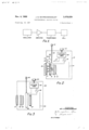
- FIG. 1 is a schematic block diagram of a power supply system usable according to the invention for energizing an electrochromic cell
- FIG. 2 is a schematic view of an electrochromic cell positioned between the lens elements of a camera, with a mechanical light blocking device arranged in front of the lens according to the invention;
- FIG. 3 is a schematic view of an electrochromic cell and a mechanical shutter arranged in series according to the invention behind the lens of a camera;
- FIG. 4 is a schematic view of an electrochromic cell and a mechanical dark slide arranged according to the invention ahead of the focal plane of a camera;
- FIG. 5 shows an electrochromic cell having electrodes arranged in correspondingly concentric annular zones for a varaible aperture cell
- FIG. 6 shows an electrochromic cell having electrodes arranged in generally parallel and linear zones for a focal plane cell
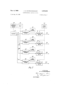
- FIG. 7 is a schematic block diagram of a control means for energizing multi-zoned electrochromic cells according to the invention.
- An electrochromic cell and a mechanical light blocking device are arranged in series across the axis of a camera lens system, but either of these elements can be arranged anywhere along the lens axis within the spirit of the invention. Thus, these elements can be placed in front of the lens, between lens elements, behind the lens, or ahead of the focal plane of the camera and the drawings show several alternative arrangements.
- FIG. 1 schematically shows an ocsillator, amplifier, and transformer arranged for energizing an electrochromic cell.
- a range of frequencies and voltages can accomplish the required cell energization depending upon the characteristics of: the cell selected, and workable voltages are generally lower than required for electrooptic crystal cells or Kerfcells which are generally energized by a high voltage capacitive discharge.
- Electrochromic cells usable in the inventive system are preferably energized by a short burst of high frequency, moderate voltage energy. The required voltages vary with the thickness of the cells selected and with other factors, and satisfactory operating voltages have fallen between 200 v. and 600 v. RMS.
- Optimum frequencies vary with the length of dipole particles and other factors, and electrochromic cells have been successfully operated according to the invention at many frequencies between 5 kcs. and 25 kcs.
- the power supply schematically illustrated in FIG. 1 is preferably battery powered, formed of solid state miniature components, and arranged to be compact and portable so as to be carried in a conventional photographic camera.
- the details of such circuitry are not part of this invention and are generally well-known to those skilled in the art.
- FIGS. 2-4 show three of the many possible arrangements of electrochromic cells and light blocking mechanisms in the inventive shutter system.
- camera 10 includes lens elements 11, 12, and 13 establishing a light path to film 14 arranged at the focal plane for exposure.
- An electrochromic cell 15 is disposed between elements 11 and 12 of the camera lens system.
- Cell 15 contains a liquid 16 in which dipole particles are suspended to form an electrochromic material.
- Liquid 16 is contained between transparent plates ,17 and 18, the inner faces of which bear transparent electrodes 19 and 20 respectively.
- High frequency energy applied to electrodes 19 and 20 orients particles in liquid 16 parallel with the axis of the camera lens system to; open cell 15 to light.
- cell 15 When not energized, cell 15 is normally opaque and closed to light with the particles in liquid 16 randomly oriented under the influence of Brownian movement.
- Power supply 21 containing the elements illustrated in FIG. 1 energizes cell 15, and exposure timer 22 controls the length of energization to determine the photographic exposure time.
- Exposure timer 22 is manually adjustable by knob 23 for preseleeting the. desired exposure time.
- Switch arm-.24 is pivotal around axis 25 for closing contacts 26 and 27 to complete the energization circuit to cell 15. Upon closure of contacts 26 and 27, energy from power supply 21 is applied to electrodes 19 and 20 to open cell 15 for a predetermined interval.
- a light blocking device 30 is arranged ahead of lens element 11 and is mounted for pivoting aroundl axis 25 with switch arm 24.
- Axis 25 also supports pinion 31 driven by a rack 32 on camera actuating button 33.
- rack 32 drives downward to rotate pinion 31 which turns spring arm 24 and lifts light blocking element 30 upward from in front of lens element 11.
- Light blocking element 30 is arranged to function as a removable lens cap, and when cap 30 is fully lifted from in front of lens element 11, contacts -26 and 27 close the circuit to cell 15 for opening the cell to transmit light to film 14 as described above.
- the duration of opening of cell 15 is controlled by timer 22 for a desired exposure after which actuator button 33 is released to own contacts 26 and 27 to allow lens cap 30 to return to its illustrated protective position in front of lens element 11.
- Camera 40 of FIG. 3 is provided with lens elements 41, 42,- and 43 establishing a light path to film 44 arranged at the focal plane for exposure. Behind lens element 43 is arranged a simple mechanical shutter 45 of fixed opening period. Shutter 45 is actuated by camera operating button 46 in a generally known manner.
- An electrochromic cell 47 behind shutter 45 is energized by a power supply 48 for an interval determined by exposure timer 49 as adjusted by knob 50.
- the energization circuit to cell 47 is completed through shutter 45 by full opening of such shutter.
- a relatively moving part in shutter 45 makes electrical contact to close the circuit to cell 47 upon full opening of shutter 45.
- Camera 60 as shown in FIG. 4 is provided with lens elements 61, 62, and 63 establishing a light path to film 64 arranged at the focal plane for exposure.
- electrochromic cell 65 Immediately ahead of film 64 is electrochromic cell 65, and ahead of cell 65 is a removable dark slide 66.
- a power supply 67 controlled by exposure timer 68 as adjusted by knob 69 controls the energization of cell 65.
- Dark slide 66 can be moved upward for removal from in front of cell 65, and such removal of dark slide 66 closes the energization circuit to cell 65. This is accomplished by electrical contact 70 engaging dark slide 66 continuously and contact 71 carried by the trailing edge of dark slide 66 engaging contact 72 to complete the energization circuit to cell 65 only when dark slide 66 is fully removed from in front of cell 65.
- Removal of dark slide 66 is accomplished by depressing camera actuator button 74 which moves rack 73 downward, this drives gear 75 to rotate gear 76 engaging a rack 77 on dark slide 66 to lift dark slide 66 relatively rapidly from in front of cell 65.
- contact 71 engages contact 72 to close the energization circuit for cell 65 to produce a timed opening of cell 65 for an exposure of film 64.
- dark slide 66 Upon release of camera actuator button 74 after exposure, dark slide 66 lowers to its illustrated position blocking light to ce 1 65.
- FIG. 5 shows an electrochromic cell 80 suitable for between or behind the lens positioning such as shown in FIGS. 2 and 3 respectively.
- Cell 80 is divided into con centric electrode zones for variable aperture energization.
- Central zone 81 is formed of coaxial circular electrodes confronting each other on each face plate of cell 80.
- Annular zone electrodes 82 encircle zones 81 on each plate of cell 80; annular zone electrodes 83 encircle zones 82 on each plate of zone 80, etc.
- concentric zones can be used as desired within the spirit of the invention.
- Zones 81-84 are separated by nonconductive spaces 85 for electrical insulation from one another. Pairs of conductors86-89 connect to each pair of electrode zones 81-84 respectively for energizing such zones to open the cell liquid between such electrodes. Selective energization through conductors 86-89 accomplishes variable aperture opening of cell 80.
- FIG. 6 shows a four-zone, electrochromic cell 90 suitable for focal plane use in camera 60 as illustrated in FIG. 4.
- Cell 90 is divided into electrode zones 91-94 extending horizontally and linearly of cell 90 and separated by nonconducting spaces 95 for electrical insulation.
- zones on cell 90 are formed by electrodes arranged in respective confronting pairs on each plate of cell 90.
- Pairs of conductors 96-99 connect to each pair of electrode zones 91-94 for energizing such 'zones successively to provide a cell-opening sweep across cell 90 for a photographic exposure.
- the period of eriergization of each zone of cell 90 can be varied as desired to control the exposure of areas on a film.
- FIG. 7 shows a power control device for energizing multizoned cells such as cell 80 or cell 90.
- Power supply 100 is connected through control switches 101-104 to provide cell zone energizeition outputs through conductors 106-109 respectively.
- Switches 101-104 are controlled respectively by triggers 111-114 preferably operating at lower power levels. Switches 101-104 are open whenever an output pulse is present from a respective control trigger 111-114. g; r
- the input to triggers.-11l-114 includes a reset input from reset 115 and pulses ihput respectively through lines 131-134 from counter 117 which is supplied by pulses from variable frequency clock 116. Also, the output intervals of triggers 111-114 is controlled by manually setable zone controllers 121-124; which can be independently or collectively adjusted. A pulse received from counter 117 by any trigger 111-114 in reset condition, produces an output to its respective - ⁇ switch 101-104 for an interval preselected respectively by controllers 121-124. Resetting of triggers 111-114 enables them to produce another output upon receipt of another pulse from counter 117.
- conductors 106-109 are connected respectively with conductor pairs 96-99 of cell 90.
- triggers 111-114 are reset and an exposure is initiated by starting variable frequency clock 116.
- Counter 117 is set for decade operation, and the first pulse from clock 116 produces an output in line 131 from counter 117 to trigger 111 which opens controlled switch 101 for an interval predetermined by zone control 121. This sends energy through line 106 to lines 96 of cell 90 to energize and open zone 91 for exposure.
- trigger 111 turns off, switch 101 closes, and zone 91 is de-energized to revert to normal opaqueness.
- the second pulse from clock 116 produces an output in lines 131 and 132 from decade counter 117 but since trigger 111 has been fired and not reset, the output in line 131 has no eifect.
- the output in line 132 trips trigger 112 for an output measured by controller 122 to open switch 102. This sends power through line 107 to lines 97 of cell 90 to open zone 92.
- the third pulse from counter 116 produces inelfective pulses in lines 131 and 132 and a pulse in line 133 effective to trip trigger 113 to open switch 103 sending power through line 108 to lines 98 for opening zone 93 of cell 90.
- a fourth pulse from clock 116 produces an effective pulse in lines 134 from counter 117 to trip trigger 114 for opening switch 104 to energize zone 94 of cell 90.
- operation counter 117 can also be set for ring operation to produce a single pulse successively in the lines 131-134 for each incoming pulse from clock 116.
- each of the zones 91-94 of cell 90 are successively energized and de-en'ergized in an exposure sweep across cell 90.
- the speed of such sweep is controlled by the frequency of pulses from clock 116-higher frequencies producing a fastei sweep.
- the duration of the exposure of each zone is controlled by manual setting of respective zone controllers 121-124.
- each of the zones 91-94 can be variably exposed as desired. For example, an overly bright sky can be relatively under exposed by proper setting of the proper zone controller, or a shady spot or a dark foreground can be relatively over-exposed to achieve the desired photographic purpose.
- the power control system of FIG. 7 is also usable with variable aperture cell and for such purpose, conductors 106-109 are connected respectively with conductor pairs 86-89 of cell 80.
- Variable aperture cell 80 can be operated in two differ ent ways by the power supply system of FIG. 7.
- the exposure duration is controlled by the total number of output pulses from-variable fre quency clock 116 and the aperture size is controlled by zone controllers 121-124.
- zone control 121 is set to enable trigger 111
- zone controllers 122-124 are set to enable their respective triggers 112-114 for the aperture size desired.
- controllers 123 and 124 are set to disable triggers 113 and 114.
- the output interval of the triggers is set for a slightly shorter interval than the period of variable frequency clock 116, a continuous reset is applied to the trigger by reset 115, and counter 117 is set for decade operation.
- variable cell 80 can be powered by the power control system of FIG. 7 is for zone controllers 121-124 to be set not only for enabling or disabling re spective triggers 111-114, but for zone controllers 121- 124 to set the exposure interval into eanll trigger as manually adjusted from outside the camera ⁇ : Of course, such an adjustment can be collective With such an arrangement, clock 116 does not measure'the exposure interval, triggers 111-114 are. not reset until after the exposure'is completed, and counter 117 is operated in either the decade or ring mode. t
- This sends power through line 106 to lines 86 of cell 80 to open zone 81 for the predetermined interval.
- trigger 112 is enabled by zone controller 122, and the second pulse from counter 117 produces a pulse in line 132 effective to trip trigger 112 for opening switch 102.
- This sends power through line 107 to lines 87 of. cell 80 to open zone 82 for the interval preselected by controller 112.
- the opening of outer zones of cell 80 proceeds as described for inner zones 81 and 82 on subse quent pulses from clock 116 and counter 117 providing that triggers 113 and 114 are enabled by the camera operator for a wider aperture.
- Electrode zone arrangements for electro chromie cells are possible within the spirit of the invention, and such zones can be energized simultaneously or in any sequence desired. Since the electrochromic cell in the inventive system is electronically controlled, a great variety of speeds, timing arrangement, adjustments, etc. are possible within the spirit of the invention.
- the inventive shutter system accomplishes its objects in providing an economical, simple, and reliable shutter system having few moving parts and minimal vibration.
- the inventive system is also compact, portable, fast, and photographically versatile. It combines the speed, etficiency, and variability with security, reliability and ruggedness. It provides a focal plane shutter of exceptionally high speed and with variable zone exposure to achieve many advantages of focal plane shutters without the disadvantages of slow speed and difficulty of control. It also ofiers the protection of a lens cap or dark slide without requiring inconvenient or extra motions by the camera operator or risking operator error as to removal of such items.
- a shutter system for a camera having a lens system providing a light path comprising:
- said light blocking means comprises a mechanical shutter of fixed period.
- said energizing means comprises a power supply, pulse generating means, trigger means responsive to said pulse generating means, and switch means actuated by said trigger means for com necting said preselected pairs of electrodes to said power supply.
- the system of claim 17 includes means for adjusting said trigger means to determine the interval of said energization.
Description
V... ..---w\... Un
N 1969 J. G. SCHRECKENDGUST ELECTROCHROMIC SHUTTER SYSTEM Filed Aug. 16, 1967 3 Sheets-Sheet l OSCILLATOR AMPLIFIER TRANSFORMER CELL EXPOSURE TIMER L22 III Fla 2 EXPOSURE 49 TIMER INVENTOR. JAY a. SCHREC/(ENQGUST HIS ATTORNEY 1969 J. G. SCHRECKENDGUST ELECTROCHROMIC SHUTTER SYSTEM 3 Sheets-Sheet 5 Filed Aug. 16, 1967 WIH EXPOSURE TIMER INVENTOR. JAY 6. SCHRECKENDGUST H/SATTORNEY Nov. 4, 1969 J. G. SCHRECKENDGUST 3,476,029
ELECTROCHROMIC SHUTTER SYSTEM Filed Aug. 16. 1967 3 Sheets-S'neet 1- VARIABLE FREQUENCY REsET 835? CLOCK 2/ zoNE //7 CONTROL I CONTROLLED I06 TRIGGER CONTROLLED 1 /2 zONE CONTROL /02 I CONTROLLED [07 TR'GGER CONTROLLED s ITCH /32 w I Q 1/3 zONE CONTROL CONTROLLED I08 TR'GGER CONTROLLED 1 a SWITCH 1/4 zONE /a4 CONTROL CONTROLLED TR'GGER CONTROLLED T L SWITCH I N V E NTOR. JAY G. SCHRE CKE NDGUS T HIS ATTORNEY United States Patent ABSTRACT OF THE DISCLOSURE A camera shutter system uses a normally opaque electrochromic cell and a mechanical light blocking device in series across the cameras light path and arranged so that full opening of the light blocking device closes a switch to electrically energize the cell. Such energization opens the cell to light and is maintained for a preselected interval for a photographic exposure. After the energiza tion is stopped, the cell relaxes to its opaque condition, and the mechanical device returns to its light blocking position. The light blocking device can be a variety of movable mechanical structures including a simple mechanical shutter of fixed opening period with the electrochromic cell energized upon full opening of the shutter. The cell and the light blocking device can be arranged in front of the lens, between elements of the lens, behind the lens, or ahead of the focal plane. The cell can be formed with several pairs of electrodes arranged as desired for photographic effects. Multiple electrode arrangements include concentric electrodes for a variable aperture cell and parallel zone electrodes that are variably energized for a focal plane cell.
This invention relates to a general chromic camera shutter system.
Electrochromic cells are generally known and have been used for goggles and variable density panels. Also, it has been suggested that such cells be used as camera shutters, but for various reasons they have not proved practically effective as suggested.
The objects of this invention include, without limita tion, the following:
(a) a fast, versatile, and reliable general purpose camera shutter system that is economically manufactured;
(b) a camera shutter system having relatively few moving parts and minimal vibration in operation; and
(c) a shutter system that is economical to maintain, convenient to operate, and portable, compact, and rugged.
These and other objects of the invention will be ap parent hereinafter from the specification which describes the invention, its use, operation, and preferred embodiments, from the drawings which constitute a part of the disclosure, and from the subject matter claimed.
In general, the inventive shutter system includes an electrochromic cell and a mechanical light blocking de vice arranged in series across the light path of a camera. The light blocking device can be a simple mechanical shutter of fixed period, a removable dark slide, a re= movable member positioned in front of the lens to function as a lens cap, or some other light obstructing device. Full removal of the light blocking device from the light path actuates a switch to energize the cell. The particles in the liquid suspension in the cell rapidly align with the electric field to open the cell for the interval desiredfor exposure. The cell reverts to a normally closed condition when the .timed energization stops, and thereafter, the mechanical device returns to its light blocking position. Thus, the protection afforded by a lens cap or dark slide is combined with the speed, versatility, simplicity, and
purpose electroice economy of an electrochromic cell for a decisive advance in the art of photographic shutters.
Throughout the specification and claims the term electrochromic cell or more simply cell refers to .a liquid suspension of oblong particles between substantial- 1y transparent plates," the particles being normally randomly oriented making the suspension opaque to light, but the particles being'orientable in an electric field to align their major axes with the field for opening the cell to light. Such cells can be made of a liquid suspension of submicroscopic particles of various lengths that act as dipoles aligning with a high frequency electric field passed between the plates. Transparent electrodes are formed on each plate to apply high frequency energization across the liquid suspension. A variety of liquids, particle materials and sizes, plate"'materials, electrode material and arrangements, frequencies, voltages, etc. are possible for such electrochromic cells. They are so named because of their capacity for changing their optical density in response to an electrici field. Another type of electrochromic cell included within the meaning of such term in this application is a liquid suspension of needle-like magnetic bodies normally randomly oriented to make the suspension opaque, but capable of being oriented with an electro-rnagnetic field to" open the cell to light. These and equivalent liquid particle suspension cells capable of changing their optical density in response to an electric field are included Within the meaning of the term electrochromic throughout this application. Cells such as included within this term are shown in the following U.S. Patents Pierson, No. 1,835,612; Marks, No. 3,257,903.
Electrochromic cells 1" adaptable to the invention are presently marketed under, the brand name of Varad by the Marx Polarized Corporation of Whitestone, N.Y.
Various crystals, birefringent materials and Kerr cells have been used for special purpose and high speed photographic shutters, but these have not been satisfactory for general purpose cameras. Kerr cells, polarizers, and crystal structures are expensive, and crystals in particular are limited to relatively small size. Furthermore, such cells require high voltages for energization, and their power supplies are large, heavy, and expensive. Accordingly, at the present time, no portable electrooptic crystal cells or Kerr cells havebeen available for use as a gen= eral purpose photograp shutter.
When electrochrom ells are referred to in the specification and claims as d to light, this means either random orientation of the suspended particles under the influence of Brownian movement, or orientation of the particles transverse to the light transmission axis in response to an applied electric field. Conversely, open refers to orientation of the cell particles in an electric field so as to transmit light through the cell as desired for photographic purposes. Such orientation is normally parallel with the axis of the camera lens system, but it could be oblique to such axis for special photographic purposes.
In the drawings:
FIG. 1 is a schematic block diagram of a power supply system usable according to the invention for energizing an electrochromic cell;
FIG. 2 is a schematic view of an electrochromic cell positioned between the lens elements of a camera, with a mechanical light blocking device arranged in front of the lens according to the invention;
FIG. 3 is a schematic view of an electrochromic cell and a mechanical shutter arranged in series according to the invention behind the lens of a camera;
FIG. 4 is a schematic view of an electrochromic cell and a mechanical dark slide arranged according to the invention ahead of the focal plane of a camera;
FIG. 5 shows an electrochromic cell having electrodes arranged in correspondingly concentric annular zones for a varaible aperture cell;
FIG. 6 shows an electrochromic cell having electrodes arranged in generally parallel and linear zones for a focal plane cell; and
FIG. 7 is a schematic block diagram of a control means for energizing multi-zoned electrochromic cells according to the invention.
An electrochromic cell and a mechanical light blocking device are arranged in series across the axis of a camera lens system, but either of these elements can be arranged anywhere along the lens axis within the spirit of the invention. Thus, these elements can be placed in front of the lens, between lens elements, behind the lens, or ahead of the focal plane of the camera and the drawings show several alternative arrangements. I
A variety of generally known electronic power supply systems can be used for energizing an electrochromic cell in the inventive shutter system. FIG. 1 schematically shows an ocsillator, amplifier, and transformer arranged for energizing an electrochromic cell. A range of frequencies and voltages can accomplish the required cell energization depending upon the characteristics of: the cell selected, and workable voltages are generally lower than required for electrooptic crystal cells or Kerfcells which are generally energized by a high voltage capacitive discharge. Electrochromic cells usable in the inventive system are preferably energized by a short burst of high frequency, moderate voltage energy. The required voltages vary with the thickness of the cells selected and with other factors, and satisfactory operating voltages have fallen between 200 v. and 600 v. RMS. Optimum frequencies vary with the length of dipole particles and other factors, and electrochromic cells have been successfully operated according to the invention at many frequencies between 5 kcs. and 25 kcs.
The power supply schematically illustrated in FIG. 1 is preferably battery powered, formed of solid state miniature components, and arranged to be compact and portable so as to be carried in a conventional photographic camera. The details of such circuitry are not part of this invention and are generally well-known to those skilled in the art.
FIGS. 2-4 show three of the many possible arrangements of electrochromic cells and light blocking mechanisms in the inventive shutter system. In FIG. 2, camera 10 includes lens elements 11, 12, and 13 establishing a light path to film 14 arranged at the focal plane for exposure. An electrochromic cell 15 is disposed between elements 11 and 12 of the camera lens system. Cell 15 contains a liquid 16 in which dipole particles are suspended to form an electrochromic material. Liquid 16 is contained between transparent plates ,17 and 18, the inner faces of which bear transparent electrodes 19 and 20 respectively. High frequency energy applied to electrodes 19 and 20 orients particles in liquid 16 parallel with the axis of the camera lens system to; open cell 15 to light. When not energized, cell 15 is normally opaque and closed to light with the particles in liquid 16 randomly oriented under the influence of Brownian movement.
Power supply 21 containing the elements illustrated in FIG. 1 energizes cell 15, and exposure timer 22 controls the length of energization to determine the photographic exposure time. Exposure timer 22 is manually adjustable by knob 23 for preseleeting the. desired exposure time.
Switch arm-.24is pivotal around axis 25 for closing contacts 26 and 27 to complete the energization circuit to cell 15. Upon closure of contacts 26 and 27, energy from power supply 21 is applied to electrodes 19 and 20 to open cell 15 for a predetermined interval.
A light blocking device 30 is arranged ahead of lens element 11 and is mounted for pivoting aroundl axis 25 with switch arm 24. Axis 25 also supports pinion 31 driven by a rack 32 on camera actuating button 33. When button 33 is depressed, rack 32 drives downward to rotate pinion 31 which turns spring arm 24 and lifts light blocking element 30 upward from in front of lens element 11. Light blocking element 30 is arranged to function as a removable lens cap, and when cap 30 is fully lifted from in front of lens element 11, contacts -26 and 27 close the circuit to cell 15 for opening the cell to transmit light to film 14 as described above. The duration of opening of cell 15 is controlled by timer 22 for a desired exposure after which actuator button 33 is released to own contacts 26 and 27 to allow lens cap 30 to return to its illustrated protective position in front of lens element 11.
Camera 40 of FIG. 3 is provided with lens elements 41, 42,- and 43 establishing a light path to film 44 arranged at the focal plane for exposure. Behind lens element 43 is arranged a simple mechanical shutter 45 of fixed opening period. Shutter 45 is actuated by camera operating button 46 in a generally known manner.
An electrochromic cell 47 behind shutter 45 is energized by a power supply 48 for an interval determined by exposure timer 49 as adjusted by knob 50. The energization circuit to cell 47 is completed through shutter 45 by full opening of such shutter. For such purpose, a relatively moving part in shutter 45 makes electrical contact to close the circuit to cell 47 upon full opening of shutter 45.
ably fixed and relatively long intervalfor example, one a tenth of a second. As shutter 45 reaches its fuly opened position the circuit to cell 47 is closed to effect a timed Opening of cell 47 for a desired photographic exposure. At the expiration of the energization interval cell 47 reverts to its normally closed condition, and shutter 45 thereafter closes at the end of its set period. Camera 40 is then ready for exposure of another frame of film of 44.
Camera 60 as shown in FIG. 4 is provided with lens elements 61, 62, and 63 establishing a light path to film 64 arranged at the focal plane for exposure. Immediately ahead of film 64 is electrochromic cell 65, and ahead of cell 65 is a removable dark slide 66. A power supply 67 controlled by exposure timer 68 as adjusted by knob 69 controls the energization of cell 65. Dark slide 66 can be moved upward for removal from in front of cell 65, and such removal of dark slide 66 closes the energization circuit to cell 65. This is accomplished by electrical contact 70 engaging dark slide 66 continuously and contact 71 carried by the trailing edge of dark slide 66 engaging contact 72 to complete the energization circuit to cell 65 only when dark slide 66 is fully removed from in front of cell 65.
Removal of dark slide 66 is accomplished by depressing camera actuator button 74 which moves rack 73 downward, this drives gear 75 to rotate gear 76 engaging a rack 77 on dark slide 66 to lift dark slide 66 relatively rapidly from in front of cell 65. At the top of the travel of dark slide 66, contact 71 engages contact 72 to close the energization circuit for cell 65 to produce a timed opening of cell 65 for an exposure of film 64. Upon release of camera actuator button 74 after exposure, dark slide 66 lowers to its illustrated position blocking light to ce 1 65.
FIG. 5 shows an electrochromic cell 80 suitable for between or behind the lens positioning such as shown in FIGS. 2 and 3 respectively. Cell 80 is divided into con centric electrode zones for variable aperture energization. Central zone 81 is formed of coaxial circular electrodes confronting each other on each face plate of cell 80. Annular zone electrodes 82 encircle zones 81 on each plate of cell 80; annular zone electrodes 83 encircle zones 82 on each plate of zone 80, etc. Of course, as many concentric zones can be used as desired within the spirit of the invention.
Zones 81-84 are separated by nonconductive spaces 85 for electrical insulation from one another. Pairs of conductors86-89 connect to each pair of electrode zones 81-84 respectively for energizing such zones to open the cell liquid between such electrodes. Selective energization through conductors 86-89 accomplishes variable aperture opening of cell 80.
FIG. 6 shows a four-zone, electrochromic cell 90 suitable for focal plane use in camera 60 as illustrated in FIG. 4. Cell 90 is divided into electrode zones 91-94 extending horizontally and linearly of cell 90 and separated by nonconducting spaces 95 for electrical insulation. As with cell 80, zones on cell 90 are formed by electrodes arranged in respective confronting pairs on each plate of cell 90. Also, any desired number of zones can be used. Pairs of conductors 96-99 connect to each pair of electrode zones 91-94 for energizing such 'zones successively to provide a cell-opening sweep across cell 90 for a photographic exposure. The period of eriergization of each zone of cell 90 can be varied as desired to control the exposure of areas on a film.
FIG. 7 shows a power control device for energizing multizoned cells such as cell 80 or cell 90. Power supply 100 is connected through control switches 101-104 to provide cell zone energizeition outputs through conductors 106-109 respectively. Switches 101-104 are controlled respectively by triggers 111-114 preferably operating at lower power levels. Switches 101-104 are open whenever an output pulse is present from a respective control trigger 111-114. g; r
The input to triggers.-11l-114 includes a reset input from reset 115 and pulses ihput respectively through lines 131-134 from counter 117 which is supplied by pulses from variable frequency clock 116. Also, the output intervals of triggers 111-114 is controlled by manually setable zone controllers 121-124; which can be independently or collectively adjusted. A pulse received from counter 117 by any trigger 111-114 in reset condition, produces an output to its respective -{switch 101-104 for an interval preselected respectively by controllers 121-124. Resetting of triggers 111-114 enables them to produce another output upon receipt of another pulse from counter 117.
To operate the zones of cell 90 with the power control system of FIG. 7, conductors 106-109 are connected respectively with conductor pairs 96-99 of cell 90. Of course, any additional or lesser number of zones and corresponding control components can be used according to the invention. With such an arrangement, triggers 111-114 are reset and an exposure is initiated by starting variable frequency clock 116. Counter 117 is set for decade operation, and the first pulse from clock 116 produces an output in line 131 from counter 117 to trigger 111 which opens controlled switch 101 for an interval predetermined by zone control 121. This sends energy through line 106 to lines 96 of cell 90 to energize and open zone 91 for exposure. When the interval preselected by controller 121 expires, trigger 111 turns off, switch 101 closes, and zone 91 is de-energized to revert to normal opaqueness. The second pulse from clock 116 produces an output in lines 131 and 132 from decade counter 117 but since trigger 111 has been fired and not reset, the output in line 131 has no eifect. The output in line 132 trips trigger 112 for an output measured by controller 122 to open switch 102. This sends power through line 107 to lines 97 of cell 90 to open zone 92. The third pulse from counter 116 produces inelfective pulses in lines 131 and 132 and a pulse in line 133 effective to trip trigger 113 to open switch 103 sending power through line 108 to lines 98 for opening zone 93 of cell 90.
Finally, a fourth pulse from clock 116 produces an effective pulse in lines 134 from counter 117 to trip trigger 114 for opening switch 104 to energize zone 94 of cell 90.
For the above described operation counter 117 can also be set for ring operation to produce a single pulse successively in the lines 131-134 for each incoming pulse from clock 116.
,After the exposure is completed by subsequent energization of zones 91-94, clock 116 is turned off, counter 117 is reset to receive a first pulse, and resetting of triggers 111-114 is accomplished by reset mechanism 115. The control system is then in condition for a subsequent ex-= posure.
Thus, it can be seen that each of the zones 91-94 of cell 90 are successively energized and de-en'ergized in an exposure sweep across cell 90. The speed of such sweep is controlled by the frequency of pulses from clock 116-higher frequencies producing a fastei sweep. The duration of the exposure of each zone is controlled by manual setting of respective zone controllers 121-124. By this, each of the zones 91-94 can be variably exposed as desired. For example, an overly bright sky can be relatively under exposed by proper setting of the proper zone controller, or a shady spot or a dark foreground can be relatively over-exposed to achieve the desired photographic purpose.
The power control system of FIG. 7 is also usable with variable aperture cell and for such purpose, conductors 106-109 are connected respectively with conductor pairs 86-89 of cell 80.
Variable aperture cell 80 can be operated in two differ ent ways by the power supply system of FIG. 7. In one mode of operation, the exposure duration is controlled by the total number of output pulses from-variable fre quency clock 116 and the aperture size is controlled by zone controllers 121-124. By manual adjustment from outside the camera, zone control 121 is set to enable trigger 111, and zone controllers 122-124 are set to enable their respective triggers 112-114 for the aperture size desired. For example, if it is not desired to open zones 83 and 84, then controllers 123 and 124 are set to disable triggers 113 and 114. Also, with such an arrangement, the output interval of the triggers is set for a slightly shorter interval than the period of variable frequency clock 116, a continuous reset is applied to the trigger by reset 115, and counter 117 is set for decade operation.
Then, as pulses from clock 116 are applied to triggers 111-114 from decade counter 117, the enabled triggers are opened with each pulse from the counter, and the ex= posure end when the pulses cease.
Another way the variable cell 80 can be powered by the power control system of FIG. 7 is for zone controllers 121-124 to be set not only for enabling or disabling re spective triggers 111-114, but for zone controllers 121- 124 to set the exposure interval into eanll trigger as manually adjusted from outside the camera}: Of course, such an adjustment can be collective With such an arrangement, clock 116 does not measure'the exposure interval, triggers 111-114 are. not reset until after the exposure'is completed, and counter 117 is operated in either the decade or ring mode. t
In such operation, a first pulse from clock 16 pro= duces an output in line 131 from counter 117 to trip enabled trigger 111 for an interval set by bontroller 121 to open switch 101 for the desired interval. This sends power through line 106 to lines 86 of cell 80 to open zone 81 for the predetermined interval. If a larger aperture is desired, trigger 112 is enabled by zone controller 122, and the second pulse from counter 117 produces a pulse in line 132 effective to trip trigger 112 for opening switch 102. This sends power through line 107 to lines 87 of. cell 80 to open zone 82 for the interval preselected by controller 112. The opening of outer zones of cell 80 proceeds as described for inner zones 81 and 82 on subse quent pulses from clock 116 and counter 117 providing that triggers 113 and 114 are enabled by the camera operator for a wider aperture.
Many other electrode zone arrangements for electro chromie cells are possible within the spirit of the invention, and such zones can be energized simultaneously or in any sequence desired. Since the electrochromic cell in the inventive system is electronically controlled, a great variety of speeds, timing arrangement, adjustments, etc. are possible within the spirit of the invention.
Thus it will be seen that the inventive shutter system accomplishes its objects in providing an economical, simple, and reliable shutter system having few moving parts and minimal vibration. The inventive system is also compact, portable, fast, and photographically versatile. It combines the speed, etficiency, and variability with security, reliability and ruggedness. It provides a focal plane shutter of exceptionally high speed and with variable zone exposure to achieve many advantages of focal plane shutters without the disadvantages of slow speed and difficulty of control. It also ofiers the protection of a lens cap or dark slide without requiring inconvenient or extra motions by the camera operator or risking operator error as to removal of such items.
"While the invention has been disclosed herein by reference to the details of preferred embodiments, it is to be understood that such disclosure is intended in an illustrative rather than a limiting sense, and it is contemplated that various modifications of the construction and arrangement of the parts will readily occur to those skilled in the art within the spirit of the invention and the scope of the appended claims.
I claim:
1. A shutter system for a camera having a lens system providing a light path, said shutter system comprising:
(a) an electrochromic cell arranged across said light path, said cell being normally closed to light;
(b) electric means for energizing said cell to open said cell to light;
(c) electric switch means for actuating said energizing means to open said cell;
(d) movable light blocking means normally arranged across said light path;
(e) means for moving said light blocking means from said light path; and
(f) means for actuating said switch means upon re-= moval of said light blocking means from said light path.
2. The system of claim 1 wherein said light blocking means comprises a mechanical shutter of fixed period.
3. The system of claim 2 wherein said actuating means is arranged for actuating said mechanical shutter.
4. The system of claim 1 wherein said electric energization .means includes means for varying the interval of said energization.
5. The system of claim 1 wherein said cell is arranged between elements of said lens system.
6. The system of claim 1 wherein said cell is arranged behind said lens system.
7. The system of claim 1 wherein said cell is arranged in the region of the focal plane of said lens system.
8. The system of claim 1 wherein said light blocking means is arranged adjacent said cell.
9. The system of claim 1 wherein said light blocking means is arranged in front of said lens system.
10. The system of claim 1 wherein said light blocking means is arranged between elements of said lens system.
11. The system of claim 1 wherein said light blocking means is arranged behind said lens system.
12. The system of claim 1 wherein said light blocking .means is arranged in the region of the focal plane of said lens system.
13. The system of claim 1 wherein said cell is formed with a plurality of pairs of electrodes, and wherein said energizing means is arranged for preselected energization of said pairs of electrodes.
14. The system of claim 13 wherein said pairs of electrodes are arranged in correspondingly concentric annular zones on opposite sides of said cell.
15 The system of claim 13 wherein said pairs of electrodes are arranged in generally parallel and linear zones on opposite sides of said cell.
16. The system of claim 15 wherein said energizing means is arranged for energizing said pairs of electrodes in succession.
17. The system of claim 13 wherein said energizing means comprises a power supply, pulse generating means, trigger means responsive to said pulse generating means, and switch means actuated by said trigger means for com necting said preselected pairs of electrodes to said power supply.
18. The system of claim 17 includes means for adjusting said trigger means to determine the interval of said energization.
References Cited UNITED STATES PATENTS 3,270,638 9/1966 Anwyl 350- 3,322,482 5/1967 Harmon 350-267 3,342,539 9/1967 Nelson 350-160 3,402,001 9/1968 Fleisher 350-160 NORTON ANSHER, Primary Examiner L. H. MCCORMICK, JR., Assistant Examiner US. Cl. X.R.
Applications Claiming Priority (1)
| Application Number | Priority Date | Filing Date | Title |
|---|---|---|---|
| US66110067A | 1967-08-16 | 1967-08-16 |
Publications (1)
| Publication Number | Publication Date |
|---|---|
| US3476029A true US3476029A (en) | 1969-11-04 |
Family
ID=24652208
Family Applications (1)
| Application Number | Title | Priority Date | Filing Date |
|---|---|---|---|
| US661100A Expired - Lifetime US3476029A (en) | 1967-08-16 | 1967-08-16 | Electrochromic shutter system |
Country Status (2)
| Country | Link |
|---|---|
| US (1) | US3476029A (en) |
| GB (1) | GB1209219A (en) |
Cited By (29)
| Publication number | Priority date | Publication date | Assignee | Title |
|---|---|---|---|---|
| US3815982A (en) * | 1971-11-13 | 1974-06-11 | Agfa Gevaert Ag | Motion picture fade-out and fade-in arrangement using a fluid crystal |
| DE2329014A1 (en) * | 1973-06-07 | 1975-01-02 | Agfa Gevaert Ag | PHOTOGRAPHIC CAMERA |
| US3890628A (en) * | 1973-10-23 | 1975-06-17 | Motorola Inc | Liquid crystal light control device and circuit |
| FR2285630A1 (en) * | 1974-09-18 | 1976-04-16 | Nippon Kogaku Kk | DEVICE FOR ADJUSTING THE EXPOSURE OF A PHOTOGRAPHIC CAMERA |
| US4050814A (en) * | 1974-12-24 | 1977-09-27 | Rockwell International Corporation | Programmable light control matrix device |
| JPS5325429A (en) * | 1977-06-06 | 1978-03-09 | Nippon Chemical Ind | Camera exposure controller using electrooptic light control element |
| JPS53131337U (en) * | 1978-03-02 | 1978-10-18 | ||
| JPS54106838U (en) * | 1978-09-18 | 1979-07-27 | ||
| JPS54106837U (en) * | 1978-09-18 | 1979-07-27 | ||
| US4190343A (en) * | 1972-08-31 | 1980-02-26 | Agfa-Gevaert Ag | Photographic camera with exposure control utilizing a phase controllable crystal |
| US4218120A (en) * | 1978-01-17 | 1980-08-19 | Minolta Camera Kabushiki Kaisha | Electrochromic light regulator |
| US4251141A (en) * | 1978-04-18 | 1981-02-17 | Agfa-Gevaert, A.G. | Shutter-diaphragm system with light-totalizing circuit |
| US4333720A (en) * | 1979-06-14 | 1982-06-08 | Canon Kabushiki Kaisha | Stop control device |
| US4609275A (en) * | 1984-09-29 | 1986-09-02 | Copal Company Limited | Exposure control unit |
| US4614415A (en) * | 1973-06-04 | 1986-09-30 | Hyatt Gilbert P | Illumination signal processing system |
| FR2580827A1 (en) * | 1985-04-19 | 1986-10-24 | Thomson Cgr | RADIOLOGY INSTALLATION |
| DE3700243A1 (en) * | 1986-02-20 | 1987-08-27 | Gx Holding Ag | METHOD FOR THE ELECTRONIC PRODUCTION OF A THERMAL IMAGE AND DEVICE FOR IMPLEMENTING THE METHOD |
| US5387958A (en) * | 1992-06-30 | 1995-02-07 | Sony Electronics, Inc. | Electro-optical control of light attenuation in the optical path of a camera |
| US5398041A (en) * | 1970-12-28 | 1995-03-14 | Hyatt; Gilbert P. | Colored liquid crystal display having cooling |
| US5432526A (en) * | 1970-12-28 | 1995-07-11 | Hyatt; Gilbert P. | Liquid crystal display having conductive cooling |
| US5555069A (en) * | 1995-02-28 | 1996-09-10 | Eastman Kodak Company | Camera with electrochromic filter |
| US5724175A (en) * | 1997-01-02 | 1998-03-03 | Optical Coating Laboratory, Inc. | Electrochromic device manufacturing process |
| US5875357A (en) * | 1994-05-18 | 1999-02-23 | Fuji Photo Film Co., Ltd. | Lens-fitted photo film unit and electronic flash device for use therewith |
| DE102004059798A1 (en) * | 2004-12-10 | 2006-06-29 | Ovd Kinegram Ag | Optically variable element with electrically active layer |
| US20080124072A1 (en) * | 2006-11-24 | 2008-05-29 | Hon Hai Precision Industry Co., Ltd. | Electric shutter with electrochromic layer and camera having same |
| US20100021156A1 (en) * | 2008-07-22 | 2010-01-28 | Hon Hai Precision Industry Co., Ltd. | Shutter and camera module with same |
| US20150126849A1 (en) * | 2013-11-04 | 2015-05-07 | Samsung Medison Co., Ltd. | Photoacoustic probe and photoacoustic diagnostic apparatus including same |
| US10771710B2 (en) | 2018-10-22 | 2020-09-08 | Raytheon Company | Shutter assembly for managing light relative to a photosensitive device |
| US11473616B2 (en) | 2018-10-22 | 2022-10-18 | Raytheon Company | Flexure device |
Families Citing this family (1)
| Publication number | Priority date | Publication date | Assignee | Title |
|---|---|---|---|---|
| DE102010056203A1 (en) * | 2010-08-05 | 2012-02-09 | Daimler Ag | Device and method for operating transparent surface elements |
Citations (4)
| Publication number | Priority date | Publication date | Assignee | Title |
|---|---|---|---|---|
| US3270638A (en) * | 1963-07-22 | 1966-09-06 | Eastman Kodak Co | Photometric system |
| US3322482A (en) * | 1965-04-12 | 1967-05-30 | James V Harmon | Panel for controlling light transmission by the selective orientation of free particles |
| US3342539A (en) * | 1963-12-24 | 1967-09-19 | Bell Telephone Labor Inc | Digitally responsive pattern recognition systems |
| US3402001A (en) * | 1963-06-06 | 1968-09-17 | Ibm | Selective gating of radiation |
-
1967
- 1967-08-16 US US661100A patent/US3476029A/en not_active Expired - Lifetime
-
1968
- 1968-08-16 GB GB39259/68A patent/GB1209219A/en not_active Expired
Patent Citations (4)
| Publication number | Priority date | Publication date | Assignee | Title |
|---|---|---|---|---|
| US3402001A (en) * | 1963-06-06 | 1968-09-17 | Ibm | Selective gating of radiation |
| US3270638A (en) * | 1963-07-22 | 1966-09-06 | Eastman Kodak Co | Photometric system |
| US3342539A (en) * | 1963-12-24 | 1967-09-19 | Bell Telephone Labor Inc | Digitally responsive pattern recognition systems |
| US3322482A (en) * | 1965-04-12 | 1967-05-30 | James V Harmon | Panel for controlling light transmission by the selective orientation of free particles |
Cited By (39)
| Publication number | Priority date | Publication date | Assignee | Title |
|---|---|---|---|---|
| US5398041A (en) * | 1970-12-28 | 1995-03-14 | Hyatt; Gilbert P. | Colored liquid crystal display having cooling |
| US5432526A (en) * | 1970-12-28 | 1995-07-11 | Hyatt; Gilbert P. | Liquid crystal display having conductive cooling |
| US3815982A (en) * | 1971-11-13 | 1974-06-11 | Agfa Gevaert Ag | Motion picture fade-out and fade-in arrangement using a fluid crystal |
| US4190343A (en) * | 1972-08-31 | 1980-02-26 | Agfa-Gevaert Ag | Photographic camera with exposure control utilizing a phase controllable crystal |
| US4614415A (en) * | 1973-06-04 | 1986-09-30 | Hyatt Gilbert P | Illumination signal processing system |
| DE2329014A1 (en) * | 1973-06-07 | 1975-01-02 | Agfa Gevaert Ag | PHOTOGRAPHIC CAMERA |
| US3955208A (en) * | 1973-06-07 | 1976-05-04 | Agfa-Gevaert, A.G. | Photographic camera with liquid-crystal diaphragm arrangement |
| US3890628A (en) * | 1973-10-23 | 1975-06-17 | Motorola Inc | Liquid crystal light control device and circuit |
| FR2285630A1 (en) * | 1974-09-18 | 1976-04-16 | Nippon Kogaku Kk | DEVICE FOR ADJUSTING THE EXPOSURE OF A PHOTOGRAPHIC CAMERA |
| US4054890A (en) * | 1974-09-18 | 1977-10-18 | Nippon Kogaku K.K. | Exposure control device in a camera using an electro-optic light control element |
| US4050814A (en) * | 1974-12-24 | 1977-09-27 | Rockwell International Corporation | Programmable light control matrix device |
| JPS5325429A (en) * | 1977-06-06 | 1978-03-09 | Nippon Chemical Ind | Camera exposure controller using electrooptic light control element |
| US4218120A (en) * | 1978-01-17 | 1980-08-19 | Minolta Camera Kabushiki Kaisha | Electrochromic light regulator |
| JPS53131337U (en) * | 1978-03-02 | 1978-10-18 | ||
| US4251141A (en) * | 1978-04-18 | 1981-02-17 | Agfa-Gevaert, A.G. | Shutter-diaphragm system with light-totalizing circuit |
| JPS54106837U (en) * | 1978-09-18 | 1979-07-27 | ||
| JPS54106838U (en) * | 1978-09-18 | 1979-07-27 | ||
| US4333720A (en) * | 1979-06-14 | 1982-06-08 | Canon Kabushiki Kaisha | Stop control device |
| US4609275A (en) * | 1984-09-29 | 1986-09-02 | Copal Company Limited | Exposure control unit |
| EP0200623A1 (en) * | 1985-04-19 | 1986-11-05 | Thomson-Cgr | Radiological apparatus |
| FR2580827A1 (en) * | 1985-04-19 | 1986-10-24 | Thomson Cgr | RADIOLOGY INSTALLATION |
| US4866275A (en) * | 1986-02-20 | 1989-09-12 | Gx-Holding Ag | Method for the electronic production of thermal image reproduction and apparatus for carrying out the method |
| DE3700243A1 (en) * | 1986-02-20 | 1987-08-27 | Gx Holding Ag | METHOD FOR THE ELECTRONIC PRODUCTION OF A THERMAL IMAGE AND DEVICE FOR IMPLEMENTING THE METHOD |
| US5387958A (en) * | 1992-06-30 | 1995-02-07 | Sony Electronics, Inc. | Electro-optical control of light attenuation in the optical path of a camera |
| US5875357A (en) * | 1994-05-18 | 1999-02-23 | Fuji Photo Film Co., Ltd. | Lens-fitted photo film unit and electronic flash device for use therewith |
| US5555069A (en) * | 1995-02-28 | 1996-09-10 | Eastman Kodak Company | Camera with electrochromic filter |
| US5724175A (en) * | 1997-01-02 | 1998-03-03 | Optical Coating Laboratory, Inc. | Electrochromic device manufacturing process |
| US8702005B2 (en) | 2004-12-10 | 2014-04-22 | Ovd Kinegram Ag | Optically variable elements comprising an electrically active layer |
| US20080259416A1 (en) * | 2004-12-10 | 2008-10-23 | Ovd Kinegram Ag | Optically Variable Elements Comprising An Electrically Active Layer |
| DE102004059798A1 (en) * | 2004-12-10 | 2006-06-29 | Ovd Kinegram Ag | Optically variable element with electrically active layer |
| US20080124072A1 (en) * | 2006-11-24 | 2008-05-29 | Hon Hai Precision Industry Co., Ltd. | Electric shutter with electrochromic layer and camera having same |
| US20100021156A1 (en) * | 2008-07-22 | 2010-01-28 | Hon Hai Precision Industry Co., Ltd. | Shutter and camera module with same |
| US7917026B2 (en) * | 2008-07-22 | 2011-03-29 | Hon Hai Precision Industry Co., Ltd. | Shutter and camera module with same |
| US20150126849A1 (en) * | 2013-11-04 | 2015-05-07 | Samsung Medison Co., Ltd. | Photoacoustic probe and photoacoustic diagnostic apparatus including same |
| CN104605814A (en) * | 2013-11-04 | 2015-05-13 | 三星麦迪森株式会社 | Photoacoustic probe and photoacoustic diagnostic apparatus |
| US10226182B2 (en) * | 2013-11-04 | 2019-03-12 | Samsung Medison Co., Ltd. | Photoacoustic probe and photoacoustic diagnostic apparatus including same |
| CN104605814B (en) * | 2013-11-04 | 2020-06-09 | 三星麦迪森株式会社 | Photoacoustic probe and photoacoustic diagnostic apparatus including the same |
| US10771710B2 (en) | 2018-10-22 | 2020-09-08 | Raytheon Company | Shutter assembly for managing light relative to a photosensitive device |
| US11473616B2 (en) | 2018-10-22 | 2022-10-18 | Raytheon Company | Flexure device |
Also Published As
| Publication number | Publication date |
|---|---|
| GB1209219A (en) | 1970-10-21 |
Similar Documents
| Publication | Publication Date | Title |
|---|---|---|
| US3476029A (en) | Electrochromic shutter system | |
| US2179717A (en) | Automatic photographic shutter | |
| US3512876A (en) | Dipolar electro-optic structures | |
| US3881808A (en) | Liquid crystal light control device having a high transmission efficiency | |
| US3846811A (en) | Flash unit for use with camera | |
| JPS569729A (en) | Stopping-down checking device of optical system | |
| GB1263334A (en) | Focal plane shutter system | |
| US2909972A (en) | Display apparatus employing electro-optical devices | |
| US4142786A (en) | Liquid crystal display device for a camera | |
| US3374473A (en) | Bistable optically read ferroelectric memory device | |
| US3754455A (en) | Motor driven still camera | |
| GB1371995A (en) | Photographic exposure control systems | |
| US3527525A (en) | Forced closure dipolar electro-optic shutter and method | |
| US4422729A (en) | Electro-optical diaphragm with radial electrodes | |
| GB1510173A (en) | Optical shutters | |
| US3433139A (en) | Electro-optic controls for reflex cameras | |
| US3673415A (en) | Shutter operating circuit having means to close shutter when light is insufficient | |
| US2516718A (en) | Stereoscopic motion-picture film marking apparatus | |
| GB1159533A (en) | Improvements in Exposure-control Apparatus for Photographic Shutters | |
| US3635142A (en) | Exchange lens with the lens-shutter | |
| US4400072A (en) | Diaphragm device for a camera with interchangeable lenses | |
| US3144761A (en) | Lock release systems | |
| GB1067200A (en) | Nuclear blast detector | |
| US3678354A (en) | A dc motor control apparatus | |
| US3341951A (en) | Display control for testing and teaching device |