US3481269A - Printing pressure control spacer means for data encoders - Google Patents
Printing pressure control spacer means for data encoders Download PDFInfo
- Publication number
- US3481269A US3481269A US668131A US3481269DA US3481269A US 3481269 A US3481269 A US 3481269A US 668131 A US668131 A US 668131A US 3481269D A US3481269D A US 3481269DA US 3481269 A US3481269 A US 3481269A
- Authority
- US
- United States
- Prior art keywords
- printing
- platen
- indicia
- character
- mask
- Prior art date
- Legal status (The legal status is an assumption and is not a legal conclusion. Google has not performed a legal analysis and makes no representation as to the accuracy of the status listed.)
- Expired - Lifetime
Links
- 125000006850 spacer group Chemical group 0.000 title description 13
- 238000007906 compression Methods 0.000 description 4
- 239000000463 material Substances 0.000 description 4
- 238000005096 rolling process Methods 0.000 description 4
- 230000006835 compression Effects 0.000 description 3
- 230000006378 damage Effects 0.000 description 3
- 230000000284 resting effect Effects 0.000 description 3
- OKTJSMMVPCPJKN-UHFFFAOYSA-N Carbon Chemical compound [C] OKTJSMMVPCPJKN-UHFFFAOYSA-N 0.000 description 2
- 229910052799 carbon Inorganic materials 0.000 description 2
- 238000009432 framing Methods 0.000 description 2
- 239000002184 metal Substances 0.000 description 2
- 229910000760 Hardened steel Inorganic materials 0.000 description 1
- 230000015572 biosynthetic process Effects 0.000 description 1
- 238000005056 compaction Methods 0.000 description 1
- 239000002131 composite material Substances 0.000 description 1
- 238000010276 construction Methods 0.000 description 1
- 238000013480 data collection Methods 0.000 description 1
- 230000006866 deterioration Effects 0.000 description 1
- 238000004049 embossing Methods 0.000 description 1
- 230000002349 favourable effect Effects 0.000 description 1
- 239000000945 filler Substances 0.000 description 1
- 238000002347 injection Methods 0.000 description 1
- 239000007924 injection Substances 0.000 description 1
- 230000003993 interaction Effects 0.000 description 1
- 239000007769 metal material Substances 0.000 description 1
- 239000002991 molded plastic Substances 0.000 description 1
- 239000004033 plastic Substances 0.000 description 1
- 238000004321 preservation Methods 0.000 description 1
- 230000002265 prevention Effects 0.000 description 1
- 238000000926 separation method Methods 0.000 description 1
Images

Classifications
-
- B—PERFORMING OPERATIONS; TRANSPORTING
- B41—PRINTING; LINING MACHINES; TYPEWRITERS; STAMPS
- B41L—APPARATUS OR DEVICES FOR MANIFOLDING, DUPLICATING OR PRINTING FOR OFFICE OR OTHER COMMERCIAL PURPOSES; ADDRESSING MACHINES OR LIKE SERIES-PRINTING MACHINES
- B41L19/00—Duplicating or printing apparatus or machines for office or other commercial purposes, of special types or for particular purposes and not otherwise provided for
Definitions
- the data encoder uses a temporary printing plate, colloquially known as a credit card, for information pertaining solely to a given transaction.
- the plate is held in a position to be traversed by a roller platen of the encoder.
- the platen travels a fixed path on a rail which holds the platen a fixed distance from the bed of the encoder, subject only to inherent resiliency of the material from which the encoder is constructed.
- a plurality of wheels In the path of the platen, beyond the position of the credit card plate, are a plurality of wheels, each of which has a series of insignia around the periphery. For example, the wheels often carry the number 0, and 1-9.
- a plurality of such wheels mounted on a common axis will provide a settable group which may be manipulated to establish any given numerical value in printing position. This is known as the variable data of a transaction, and is used in such instance as the value of a product sold to a customer identified by the credit card plate.
- variable data wheels upon reaching the variable data wheels, the platen encounters much less foundation to resist the applied load, there being only one single data character on each wheel in the example given. Because the established close path is fixed, the platen will, therefore, overpower the single character. This fact must be considered, even though the wheels are held by a yieldable mounting. Unless the character is constructed of expensive resistant material, it will qiuckly fatigue to failure. Although the variable data wheels can be made of hardened steel or other metal for destruction resistance, cost factors strongly favor injection molded plastic which does not have favorable impact and crush resistance.
- the desired imprint pressure is obtained by relating the 3,481,269 Patented Dec. 2, 1969 relative elevation of indicia to the platen surface to space the indicia a distance less than the form thickness for the purpose of causing an imprinting pressure, but not sufficiently close that enough interference is obtained to wedge the form between the platen and the indicia with excessive force causing over-compression and damage to the printing surface of the indicia in addition to heavy printing.
- FIGURE 5 is an enlarged illustration of the FIGURE 4 structure, with a form set included.'
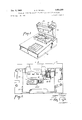
- FIGURE 1 of the drawings illustrates the common type of source data encoder commonly employed in data collection applications and similar environments.
- the operating mechanism is carried within housing 10.
- Guide board 12 is provided to assemble the various printing components in working relationship.
- a recess 13 is formed to accept the top edge of a common form of embossed credit card.
- An embossed card 15, shown in FIGURE 2 is illustrated in printing position. The recess prevents lateral shifting of the card with respect to guide board 12.
- an anvil 14 which is spring loaded in this particular type of data encoder, is positioned to underlay a portion of the credit card.
- the spring loaded anvil gives ample support to cause printing interaction pressure but will yield in the event of overloading.
- the spring loading is suggested by the arrows in FIGURE 3.
- the embossed card 15 serves the function of a panel printing plate employed as the transaction related information source. This designation is employed to convey the thought of a thin panel member, with embossed printing characters projecting from one surface.
- panel printing members have been made of metal and composition material as well as plastic material. Although the panel printing members are usually planar, such flatness is not a requirement for the present invention.
- credit card 15 as an illustration of the type of device adaptable to the present invention.
- variable data wheels 18 for setting the variable information illustrate a further type of data which compose a part of the usual encoder.
- the guide board 12 is also equipped with retractable form guides 19 and permanent fixed form guides 20 to enable an interleaved form set to be properly related to the credit card and the various printing members of the guide board.
- the printing members and the form set are placed in superposed relationship preparatory to rolling a platen over the surface of the combination stack to impress data from the card through a release carbon-of g the form set to a sheet which is encoded with the information.
- the data encoder of FIGURE 1 employs a head with a cross rail 26.
- the head pivots to an open position shown in FIGURE 1 for providing access to the guide board 12.
- the head 25 is closeable to a fixed position resting upon the guide board 12.
- a roller platen 30, carried by a yoke 31, rides the rail 26 and has a substantially unyielding path of advancement across the print carrier area of the guide board 12 wherein the variable and fixed indicia is placed.
- the head 25 carries a form clamp mask 34.
- a form clamp mask is optional, but its use has been established in the prior art, Patent 3,277,822, and the spacing concepts of this invention for embossed character preservation is extended to the credit card area by incorporating the shield as a spacer.
- Mask 34 is made of thin sheet metal with openings therethrough for framing the printing characters positioned upon the guide board.
- the mask has a narrow track edge 36 which is related to the guide board 12 in position to traverse the top edge portion of the credit card 15. This position upon the credit card is aligned with the roller platen printing path as the platen moves across the guide board 12, but the area of card 15 upon which it rests is a non-indicia pad area outside of the idicia area which contains the raised characters.
- the track edge 36 is resting upon the top surface of the card 15.
- the roller platen has an impression surface 37 which is used to cause the impression formation.
- impression surface 37 By positioning one edge of the roller platen to ride on track edge 36, the edge acts as a spacer. If the form set is placed under track edge 36 and on top of card 15, then the form set will cause the card and roller to separate to the extent of the form set thickness. Then the track edge 36 need be only related to the additional separation of platen and credit card to provide good print interference compression, but not allow the platen to rest fully upon the form set.
- Each embossed character projects from the card surface essentially a fixed distance.
- the platen In order to press the character into the form set for best printing quality, the platen must be held a fixed distance from the characters. This space is referred to by those skilled in the art as interference. If an anvil is unyielding, and the platen is unyielding, the pressure exerted on a character will increase as the form thickness is increased. The yieldable anvil 14 is used to limit the maximum pressure to prevent excessive damage.
- the spacer means must be related to the form thickness for proper results. If the form set is placed under track edge 36, then the edge 36 will provide the interference spacing. If the form set is not used under the edge 36, then the choice becomes one of increasing the thickness of edge 36 or supplying other spacing substitutes related to the form set thickness removed.
- a rim 38 incorporated on the platen edge is an example.
- the spacer means includes the body of the credit card 15 in the area of its normal thickness outside the embossed character area, and the track edge 36, acting in conjunction with the rim 38. These three make up a spacer means in the FIGURE 3 embodiment.
- a form set is suggested by the rectangular broken line indicated by reference character 39. It is shown extending just above the data characters, and not under the position of track edge 36.
- the amount of the spacing means other than the credit card itself is arbitrary and desitedfnerhog card itself, is arbitrary and designed for the form set or sets for which the device is to be used.
- raised characters 40 are shown spaced from the surface 37. Regardless of whether the spacing is done entirely by the mask track edge 36 or the combination thereof with other means, the track edge is functionally related to the actual thickness of the form which is to be inserted between the card 15 and the surface 37. Spacing is assured in order to hold the surface 37 a distance from the characters 40 and thereby prevent excessive pressure whenever a form is placed between the roller and card.
- each wheel 18 may likewise be proteeted by providing for extension of the track edge 36 to the region of the wheels.
- problems that enter into such an extension are numerous and difficult to overcome.
- a track under edge 36, to make up the loss of thickness of the credit card 15, could be carried by the machine bed, but then the interference would be fixed, and could not reflect variable form set thickness unless the form set were always used as part of the spacer means.
- this invention provides for a novel spacing over the variable wheels, the preferred embodiment of which produces other desirable results.
- Each wheel 18 must be positioned with the selected indicia brought to alignment with the plane of the card 15 for printing. If the wheel is not rotated into exact level position, a portion of the indicia character will project above the plane of the remainder of the character, and will therefore receive excessive impact. The rolling action of the platen during printing will level the character, but at the expense of excessive deterioration.
- each wheel 18 is formed with a pad 41 adjacent each indicia character.
- the form set to be encoded will consist of paper sheets and interleaved pressure release carbon sheets. Such a form set will resist compaction under fiat surface compression, but is subject to further embossing and compression by the limited surface area presented by indicia characters.
- the pad 41 is formed to a calculated elevation with respect to the indicia character elevation, such that the form and any other filler sheet placed on the pad will serve as a spacer means to separate and space the platen with respect to the indicia character.
- the form is composed of two paper sheets and one carbon sheet.
- the form clamp mask 34 is cut to overlay the series of adjacent pads 41.
- the form and the mask act jointly as a spacer means, and provide the required interference between thet platen and the indicia character. It does not matter how thick the form set may be, this same effective space will persist.
- the elevation of the pad 41 must be calculated so that in conjunction with the mask thickness it will provide the proper amount of interference between the platen and the indicia character.
- the form set thickness may vary but because the same form set overlays both the indicia and the elevated pad, the same interference will be maintained between thet platen and indicia character.
- the mask reduces the smudge printing in the pad area. Without the mask, each pad 41 prints as distinct bar. With the mask, the printing of the bars 41 is reduced to a far more acceptable level.
- a form set support bed for carrying at least one printing member
- said printing member having an indicia area and an adjacent non-indicia pad area, said areas lying in side-by-side relationship projecting above said bed;
- a printing pressure control spacer means for establishing and maintaining a minimum interference of said platen with respect to said indicia area, including means spaced laterally from said indicia area and located between said pad area and platen, said means related to the thickness of the form set to be printed for holding the platen separate from the indicia, 1
- At least one rotatable wheel and one removable panel constitute said embossed printing member
- said panel having a planar surface lying on said bed
- said wheel having at least one indicia character on the periphery thereof, said character extending co-planar with the plane of the panel character, a pad area on the wheel adjacent said character;
- a sheet member removably positionable over said pad area for clamping a form set in printing position, said pad and sheet member in conjunction with a form set constituting said control spacer means.
- a printing apparatus for printing by pressure release from an ink carrier to a receiving sheet, wherein the pressure is related to the pressure release requirements for full printing in regions of large printing area, and restrained against overwhelming smudge printing pressure in regions of lesser printing area, the printing being accomplished by a roller platen traversing a panel printing memberhaving printing characters projecting from a restricted print character area of one surface thereof, said apparatus comprising:
- spacer means including a mask of sheet material having openings for framing the printing characters, said mask superposed with the body of the printing member along a portion thereof aligned with said roller path;
- roller platen having a portion positioned to roll on said mask so that said roller will bridge over said openings with a minimum interference of said platen with respect to said printing characters;
- said printing member body outside the printing character area thereof, and the mask cooperate together with surfaces of the roller platen to prevent excessive printing pressures in areas lacking printing characters within said printing action path.
- support means for receiving a printing member and form set in superposed relationship
- roller platen means for rolling said platen in a printing action path across said printing member
- each wheel having a plurality of indicia printing characters spaced around the wheel periphery, a flat pad area adjacent each indicia, each said indicia and adjacent pad area defining a separate printing member, said plurality of wheels positionable to align a plurality of printing members into a planar array;
- a sheet member form mask said mask having an area to cover said pad areas only of the array, said pad areas having a top surface with a radius distance from the wheel center less than the radius distance to the top of the indicia such that a form to be printed and said mask in superposed relationship to said pad area provides spacer means holding said roller a predetermined distance from said indicia to produce minimum interference;
Description
A. c. BROWN 3,481,269
PRINTING PRESSURE CONTROL SPACER MEANS FOR DATA ENCODERS Dec. 2, 1969 2 Sheets-Sheet 1 Filed Sept. 15, 1967 INVENTOR ALBERT CB/POW/V BY 53'! HbE' HI B J.J.cusToMER E IZIZMAIN ST. l
HILLS MASS I I l JOES SERVICE ATTORNEY Dec. 2, 1969 A. c. BROWN 3,481,269
PRINTING PRESSURE CONTROL SPACER MEANS FOR DATA ENCODERS Filed Sept. 15, 1967 2 Sheets-Sheet INVENTOPI ALBERT 0. BROWN ATTORFE Y United States Patent 3,481,269 PRINTING PRESSURE CONTROL SPACER MEANS FOR DATA EN CODERS Albert C. Brown, Eastlake, Ohio, assignor to Addressograph-Multigraph Corporation, Cleveland, Ohio, a corporation of Delaware Filed Sept. 15, 1967, Ser. No. 668,131
Int. Cl. B41l 47/40 US. Cl. 10156 4 Claims ABSTRACT OF THE DISCLOSURE BACKGROUND OF THE INVENTION Refer to US. Patent 3,277,822 as a teaching of the general type original source data encoder under consideration, and its purpose. Such teaching is not related in the inventive sense, but is related in general use.
The data encoder uses a temporary printing plate, colloquially known as a credit card, for information pertaining solely to a given transaction. The plate is held in a position to be traversed by a roller platen of the encoder. The platen travels a fixed path on a rail which holds the platen a fixed distance from the bed of the encoder, subject only to inherent resiliency of the material from which the encoder is constructed.
In the path of the platen, beyond the position of the credit card plate, are a plurality of wheels, each of which has a series of insignia around the periphery. For example, the wheels often carry the number 0, and 1-9. A plurality of such wheels mounted on a common axis will provide a settable group which may be manipulated to establish any given numerical value in printing position. This is known as the variable data of a transaction, and is used in such instance as the value of a product sold to a customer identified by the credit card plate.
In order to impress the several lines of embossed data usually presented on a credit card, the fixed distance of the platen from the bed must be closely spaced. To assure good impression, suflicient total force must be obtained. The total force is distributed among many insignia data units.
However, upon reaching the variable data wheels, the platen encounters much less foundation to resist the applied load, there being only one single data character on each wheel in the example given. Because the established close path is fixed, the platen will, therefore, overpower the single character. This fact must be considered, even though the wheels are held by a yieldable mounting. Unless the character is constructed of expensive resistant material, it will qiuckly fatigue to failure. Although the variable data wheels can be made of hardened steel or other metal for destruction resistance, cost factors strongly favor injection molded plastic which does not have favorable impact and crush resistance.
SUMMARY OF THE INVENTION The advantage provided by this invention is found in the provision for protection of the embossed encoding characters and prevention of character distortion, by the provision of means to limit platen approach toward printing character in the device.
The desired imprint pressure is obtained by relating the 3,481,269 Patented Dec. 2, 1969 relative elevation of indicia to the platen surface to space the indicia a distance less than the form thickness for the purpose of causing an imprinting pressure, but not sufficiently close that enough interference is obtained to wedge the form between the platen and the indicia with excessive force causing over-compression and damage to the printing surface of the indicia in addition to heavy printing.
DESCRIPTION OF THE DRAWINGS ship of one rotatable varable data wheel, presenting onedata character for impression imprinting, and a form mask in position for conjunction action as a spacing means with a form set not yet placed, representative of the construction seen along line 4--4 of FIGURE 2.
FIGURE 5 is an enlarged illustration of the FIGURE 4 structure, with a form set included.'
DESCRIPTION OF THE PREFERRED EMBODIMENT FIGURE 1 of the drawings illustrates the common type of source data encoder commonly employed in data collection applications and similar environments. The operating mechanism is carried within housing 10. Guide board 12 is provided to assemble the various printing components in working relationship. A recess 13 is formed to accept the top edge of a common form of embossed credit card. An embossed card 15, shown in FIGURE 2, is illustrated in printing position. The recess prevents lateral shifting of the card with respect to guide board 12.
As seen in FIGURE 3, an anvil 14, which is spring loaded in this particular type of data encoder, is positioned to underlay a portion of the credit card. The spring loaded anvil gives ample support to cause printing interaction pressure but will yield in the event of overloading. The spring loading is suggested by the arrows in FIGURE 3.
The embossed card 15 serves the function of a panel printing plate employed as the transaction related information source. This designation is employed to convey the thought of a thin panel member, with embossed printing characters projecting from one surface. Such panel printing members have been made of metal and composition material as well as plastic material. Although the panel printing members are usually planar, such flatness is not a requirement for the present invention. Hereinafter, reference will be made only to credit card 15, as an illustration of the type of device adaptable to the present invention.
In addition to the information provided by the credit card 15, variable data wheels 18 for setting the variable information illustrate a further type of data which compose a part of the usual encoder.
The guide board 12 is also equipped with retractable form guides 19 and permanent fixed form guides 20 to enable an interleaved form set to be properly related to the credit card and the various printing members of the guide board. Thus the printing members and the form set are placed in superposed relationship preparatory to rolling a platen over the surface of the combination stack to impress data from the card through a release carbon-of g the form set to a sheet which is encoded with the information.
The data encoder of FIGURE 1 employs a head with a cross rail 26. The head pivots to an open position shown in FIGURE 1 for providing access to the guide board 12. The head 25 is closeable to a fixed position resting upon the guide board 12.
A roller platen 30, carried by a yoke 31, rides the rail 26 and has a substantially unyielding path of advancement across the print carrier area of the guide board 12 wherein the variable and fixed indicia is placed.
The head 25 carries a form clamp mask 34. A form clamp mask is optional, but its use has been established in the prior art, Patent 3,277,822, and the spacing concepts of this invention for embossed character preservation is extended to the credit card area by incorporating the shield as a spacer.
As seen in FIGURE 3, the track edge 36 is resting upon the top surface of the card 15.
The roller platen has an impression surface 37 which is used to cause the impression formation. By positioning one edge of the roller platen to ride on track edge 36, the edge acts as a spacer. If the form set is placed under track edge 36 and on top of card 15, then the form set will cause the card and roller to separate to the extent of the form set thickness. Then the track edge 36 need be only related to the additional separation of platen and credit card to provide good print interference compression, but not allow the platen to rest fully upon the form set.
Each embossed character projects from the card surface essentially a fixed distance. In order to press the character into the form set for best printing quality, the platen must be held a fixed distance from the characters. This space is referred to by those skilled in the art as interference. If an anvil is unyielding, and the platen is unyielding, the pressure exerted on a character will increase as the form thickness is increased. The yieldable anvil 14 is used to limit the maximum pressure to prevent excessive damage.
The spacer means must be related to the form thickness for proper results. If the form set is placed under track edge 36, then the edge 36 will provide the interference spacing. If the form set is not used under the edge 36, then the choice becomes one of increasing the thickness of edge 36 or supplying other spacing substitutes related to the form set thickness removed. A rim 38 incorporated on the platen edge is an example. The spacer means includes the body of the credit card 15 in the area of its normal thickness outside the embossed character area, and the track edge 36, acting in conjunction with the rim 38. These three make up a spacer means in the FIGURE 3 embodiment. In FIGURE 2, a form set is suggested by the rectangular broken line indicated by reference character 39. It is shown extending just above the data characters, and not under the position of track edge 36.
The amount of the spacing means other than the credit card itself, is arbitrary and desitedfnerhog card itself, is arbitrary and designed for the form set or sets for which the device is to be used. In FIGURE 3, raised characters 40 are shown spaced from the surface 37. Regardless of whether the spacing is done entirely by the mask track edge 36 or the combination thereof with other means, the track edge is functionally related to the actual thickness of the form which is to be inserted between the card 15 and the surface 37. Spacing is assured in order to hold the surface 37 a distance from the characters 40 and thereby prevent excessive pressure whenever a form is placed between the roller and card.
The character on each wheel 18 may likewise be proteeted by providing for extension of the track edge 36 to the region of the wheels. However, the problems that enter into such an extension are numerous and difficult to overcome. A track under edge 36, to make up the loss of thickness of the credit card 15, could be carried by the machine bed, but then the interference would be fixed, and could not reflect variable form set thickness unless the form set were always used as part of the spacer means.
Therefore, this invention provides for a novel spacing over the variable wheels, the preferred embodiment of which produces other desirable results.
Each wheel 18 must be positioned with the selected indicia brought to alignment with the plane of the card 15 for printing. If the wheel is not rotated into exact level position, a portion of the indicia character will project above the plane of the remainder of the character, and will therefore receive excessive impact. The rolling action of the platen during printing will level the character, but at the expense of excessive deterioration.
According to the preferred form of this invention, each wheel 18 is formed with a pad 41 adjacent each indicia character. The form set to be encoded will consist of paper sheets and interleaved pressure release carbon sheets. Such a form set will resist compaction under fiat surface compression, but is subject to further embossing and compression by the limited surface area presented by indicia characters.
The pad 41 is formed to a calculated elevation with respect to the indicia character elevation, such that the form and any other filler sheet placed on the pad will serve as a spacer means to separate and space the platen with respect to the indicia character. In the usual service station situation, for example only, the form is composed of two paper sheets and one carbon sheet.
In the preferred embodiment, as illustrated, the form clamp mask 34 is cut to overlay the series of adjacent pads 41. The form and the mask act jointly as a spacer means, and provide the required interference between thet platen and the indicia character. It does not matter how thick the form set may be, this same effective space will persist.
The elevation of the pad 41 must be calculated so that in conjunction with the mask thickness it will provide the proper amount of interference between the platen and the indicia character. The form set thickness may vary but because the same form set overlays both the indicia and the elevated pad, the same interference will be maintained between thet platen and indicia character.
It is a further discovery of this invention that the use of the clamp mask 34 over the pads is preferable rather than to increase the pad elevation, because the single sheet mask will urge all the pads to assume an essentially uniform level position. The prior art leveling devices are limited in effectiveness, but a single sheet over all the pads 41 has been discovered to cause all the wheels to come into near perfect alignment.
Also, for aesthetic purposes, the mask reduces the smudge printing in the pad area. Without the mask, each pad 41 prints as distinct bar. With the mask, the printing of the bars 41 is reduced to a far more acceptable level.
What is claimed is:
1. A printing apparatus for printing by pressure release from an ink carrier to a receiving sheet, wherein the pressure is related to the pressure release requirement for full printing in regions of large printing area, and restrained against overwhelming smudge printing pressure in regions of lesser printing area, comprising:
a form set support bed for carrying at least one printing member;
said printing member having an indicia area and an adjacent non-indicia pad area, said areas lying in side-by-side relationship projecting above said bed;
a roller platen, and means for causing said platen to traverse said bed; and
a printing pressure control spacer means for establishing and maintaining a minimum interference of said platen with respect to said indicia area, including means spaced laterally from said indicia area and located between said pad area and platen, said means related to the thickness of the form set to be printed for holding the platen separate from the indicia, 1
but with a space less than the thickness of the form set.
2. A printing apparatus as defined in claim 1, further characterized in that:
at least one rotatable wheel and one removable panel constitute said embossed printing member;
said panel having a planar surface lying on said bed,
and one or more indicia characters embossed therein and projecting upwardly towards said roller platen path;
said wheel having at least one indicia character on the periphery thereof, said character extending co-planar with the plane of the panel character, a pad area on the wheel adjacent said character; and
a sheet member removably positionable over said pad area for clamping a form set in printing position, said pad and sheet member in conjunction with a form set constituting said control spacer means.
3. A printing apparatus for printing by pressure release from an ink carrier to a receiving sheet, wherein the pressure is related to the pressure release requirements for full printing in regions of large printing area, and restrained against overwhelming smudge printing pressure in regions of lesser printing area, the printing being accomplished by a roller platen traversing a panel printing memberhaving printing characters projecting from a restricted print character area of one surface thereof, said apparatus comprising:
support means for receiving the printing member and form set in superposed relationship; a roller platen, means for rolling said platen in a printing action path across said printing member;
spacer means including a mask of sheet material having openings for framing the printing characters, said mask superposed with the body of the printing member along a portion thereof aligned with said roller path; and
said roller platen having a portion positioned to roll on said mask so that said roller will bridge over said openings with a minimum interference of said platen with respect to said printing characters;
whereby said printing member body outside the printing character area thereof, and the mask, cooperate together with surfaces of the roller platen to prevent excessive printing pressures in areas lacking printing characters within said printing action path.
4. A printing apparatus for printing by pressure release from an ink carrier to a receiving sheet, wherein the pressure is related to the pressure release requirements for full printing in regions of large printing area, and restrained against overwhelming smudge printing pressure in regions of lesser printing area, comprising:
support means for receiving a printing member and form set in superposed relationship;
a roller platen, means for rolling said platen in a printing action path across said printing member;
a plurality of variable data wheels, means to mount said wheels in a group for rotation of the periphery of each wheel with respect to said support means, each said wheel having a plurality of indicia printing characters spaced around the wheel periphery, a flat pad area adjacent each indicia, each said indicia and adjacent pad area defining a separate printing member, said plurality of wheels positionable to align a plurality of printing members into a planar array;
a sheet member form mask, said mask having an area to cover said pad areas only of the array, said pad areas having a top surface with a radius distance from the wheel center less than the radius distance to the top of the indicia such that a form to be printed and said mask in superposed relationship to said pad area provides spacer means holding said roller a predetermined distance from said indicia to produce minimum interference; and
means to clamp said mask in place over a form, and thereafter guide said roller platen along in a printing path resting upon said mask as a guide.
References Cited UNITED STATES PATENTS 1,080,202 12/1913 Duncan 101-56 1,953,632 4/1934 Putnam et al 101-110 1,981,001 11/1934 Osborn 101-269 XR 2,092,026 9/1937 Schaefer 101-56 2,359,849 10/1944 Hoeber 101-56 3,138,091 6/1964 Maul 101-269 XR ROBERT E. PULFREY, Primary Examiner C. D. CROWDER, Assistant Examiner US. Cl. X.R. 101-269
Applications Claiming Priority (1)
| Application Number | Priority Date | Filing Date | Title |
|---|---|---|---|
| US66813167A | 1967-09-15 | 1967-09-15 |
Publications (1)
| Publication Number | Publication Date |
|---|---|
| US3481269A true US3481269A (en) | 1969-12-02 |
Family
ID=24681139
Family Applications (1)
| Application Number | Title | Priority Date | Filing Date |
|---|---|---|---|
| US668131A Expired - Lifetime US3481269A (en) | 1967-09-15 | 1967-09-15 | Printing pressure control spacer means for data encoders |
Country Status (4)
| Country | Link |
|---|---|
| US (1) | US3481269A (en) |
| DE (1) | DE1786293A1 (en) |
| FR (1) | FR1570962A (en) |
| GB (1) | GB1230464A (en) |
Cited By (6)
| Publication number | Priority date | Publication date | Assignee | Title |
|---|---|---|---|---|
| US3577917A (en) * | 1969-08-04 | 1971-05-11 | Addressograph Multigraph | Printing machines with shifting roller platen |
| US3709144A (en) * | 1971-11-10 | 1973-01-09 | Addressograph Multigraph | Data board and data recording machine |
| US3712211A (en) * | 1970-10-30 | 1973-01-23 | Burroughs Corp | Alignment means for a bed and platen printing machine |
| US3756151A (en) * | 1971-03-12 | 1973-09-04 | Addressograph Multigraph | Compensating platen for printing machines |
| US3904010A (en) * | 1972-07-14 | 1975-09-09 | Triumph Werke Nuernberg Ag | Typewriter carriage assembly |
| US4024816A (en) * | 1976-02-05 | 1977-05-24 | Dayco Corporation | Inking roller and apparatus and method for printing using such roller |
Citations (6)
| Publication number | Priority date | Publication date | Assignee | Title |
|---|---|---|---|---|
| US1080202A (en) * | 1912-04-05 | 1913-12-02 | Addressograph Co | Addressing-machine. |
| US1953632A (en) * | 1932-05-28 | 1934-04-03 | Markem Machine Co | Type holder for marking machines |
| US1981001A (en) * | 1932-05-19 | 1934-11-20 | Addressograph Co | Addressing machine |
| US2092026A (en) * | 1935-07-27 | 1937-09-07 | Addressograph Multigraph | Printing device |
| US2359849A (en) * | 1940-10-17 | 1944-10-10 | Addressograph Multigraph | Printing machine |
| US3138091A (en) * | 1964-06-23 | Printing machines |
-
1967
- 1967-09-15 US US668131A patent/US3481269A/en not_active Expired - Lifetime
-
1968
- 1968-06-20 FR FR1570962D patent/FR1570962A/fr not_active Expired
- 1968-09-13 DE DE19681786293 patent/DE1786293A1/en active Pending
- 1968-09-16 GB GB1230464D patent/GB1230464A/en not_active Expired
Patent Citations (6)
| Publication number | Priority date | Publication date | Assignee | Title |
|---|---|---|---|---|
| US3138091A (en) * | 1964-06-23 | Printing machines | ||
| US1080202A (en) * | 1912-04-05 | 1913-12-02 | Addressograph Co | Addressing-machine. |
| US1981001A (en) * | 1932-05-19 | 1934-11-20 | Addressograph Co | Addressing machine |
| US1953632A (en) * | 1932-05-28 | 1934-04-03 | Markem Machine Co | Type holder for marking machines |
| US2092026A (en) * | 1935-07-27 | 1937-09-07 | Addressograph Multigraph | Printing device |
| US2359849A (en) * | 1940-10-17 | 1944-10-10 | Addressograph Multigraph | Printing machine |
Cited By (6)
| Publication number | Priority date | Publication date | Assignee | Title |
|---|---|---|---|---|
| US3577917A (en) * | 1969-08-04 | 1971-05-11 | Addressograph Multigraph | Printing machines with shifting roller platen |
| US3712211A (en) * | 1970-10-30 | 1973-01-23 | Burroughs Corp | Alignment means for a bed and platen printing machine |
| US3756151A (en) * | 1971-03-12 | 1973-09-04 | Addressograph Multigraph | Compensating platen for printing machines |
| US3709144A (en) * | 1971-11-10 | 1973-01-09 | Addressograph Multigraph | Data board and data recording machine |
| US3904010A (en) * | 1972-07-14 | 1975-09-09 | Triumph Werke Nuernberg Ag | Typewriter carriage assembly |
| US4024816A (en) * | 1976-02-05 | 1977-05-24 | Dayco Corporation | Inking roller and apparatus and method for printing using such roller |
Also Published As
| Publication number | Publication date |
|---|---|
| FR1570962A (en) | 1969-06-13 |
| GB1230464A (en) | 1971-05-05 |
| DE1786293A1 (en) | 1971-12-30 |
Similar Documents
| Publication | Publication Date | Title |
|---|---|---|
| US3481269A (en) | Printing pressure control spacer means for data encoders | |
| US2982205A (en) | Printing apparatus | |
| US3577917A (en) | Printing machines with shifting roller platen | |
| US3838641A (en) | Portable, lightweight imprinting apparatus | |
| GB1587108A (en) | Screen printing press | |
| GB1563516A (en) | Device for printing braile | |
| US2237363A (en) | Method of and apparatus for copying printed matter | |
| US3283711A (en) | Printing roller vertical position control device | |
| US3608485A (en) | Clipboard data recorder | |
| US3516356A (en) | Platen for a source data machine | |
| US3780669A (en) | Imprinter having independently mounted, preloaded print rollers | |
| US2060190A (en) | Article and process for multiplying records | |
| US2720833A (en) | Methods and arrangements for carrying out postcard billing operations and the like | |
| GB989670A (en) | Type carrier for high speed printing mechanism | |
| US3143063A (en) | Double print preventing shield in web printing machines | |
| US3756151A (en) | Compensating platen for printing machines | |
| US4043263A (en) | Printing machine with vertically shiftable credit card supporting plate | |
| US5303646A (en) | Relief printing method and apparatus for its implementation | |
| US3242859A (en) | Compensating anvil means for a printing machine | |
| US1861572A (en) | Documentary seal | |
| US3820458A (en) | Elimination of uncontrolled background reproduction during printing | |
| US1726803A (en) | Printing for the blind | |
| US3789755A (en) | Printing devices for calculating apparatus | |
| US3556007A (en) | Data recording system | |
| US3400659A (en) | Printing arrangements |
Legal Events
| Date | Code | Title | Description |
|---|---|---|---|
| AS | Assignment |
Owner name: DBS, INC., A MA CORP. Free format text: ASSIGNMENT OF ASSIGNORS INTEREST.;ASSIGNOR:AM INTERNATIONAL, INC.;REEL/FRAME:003979/0673 Effective date: 19820325 |