US3537094A - Total security alarm system - Google Patents
Total security alarm system Download PDFInfo
- Publication number
- US3537094A US3537094A US827108A US3537094DA US3537094A US 3537094 A US3537094 A US 3537094A US 827108 A US827108 A US 827108A US 3537094D A US3537094D A US 3537094DA US 3537094 A US3537094 A US 3537094A
- Authority
- US
- United States
- Prior art keywords
- switch
- alarm
- line
- apartment
- total security
- Prior art date
- Legal status (The legal status is an assumption and is not a legal conclusion. Google has not performed a legal analysis and makes no representation as to the accuracy of the status listed.)
- Expired - Lifetime
Links
Images


Classifications
-
- G—PHYSICS
- G08—SIGNALLING
- G08B—SIGNALLING OR CALLING SYSTEMS; ORDER TELEGRAPHS; ALARM SYSTEMS
- G08B25/00—Alarm systems in which the location of the alarm condition is signalled to a central station, e.g. fire or police telegraphic systems
- G08B25/008—Alarm setting and unsetting, i.e. arming or disarming of the security system
-
- G—PHYSICS
- G08—SIGNALLING
- G08B—SIGNALLING OR CALLING SYSTEMS; ORDER TELEGRAPHS; ALARM SYSTEMS
- G08B13/00—Burglar, theft or intruder alarms
- G08B13/02—Mechanical actuation
- G08B13/06—Mechanical actuation by tampering with fastening
-
- G—PHYSICS
- G08—SIGNALLING
- G08B—SIGNALLING OR CALLING SYSTEMS; ORDER TELEGRAPHS; ALARM SYSTEMS
- G08B13/00—Burglar, theft or intruder alarms
- G08B13/02—Mechanical actuation
- G08B13/08—Mechanical actuation by opening, e.g. of door, of window, of drawer, of shutter, of curtain, of blind
-
- G—PHYSICS
- G08—SIGNALLING
- G08B—SIGNALLING OR CALLING SYSTEMS; ORDER TELEGRAPHS; ALARM SYSTEMS
- G08B19/00—Alarms responsive to two or more different undesired or abnormal conditions, e.g. burglary and fire, abnormal temperature and abnormal rate of flow
-
- G—PHYSICS
- G08—SIGNALLING
- G08B—SIGNALLING OR CALLING SYSTEMS; ORDER TELEGRAPHS; ALARM SYSTEMS
- G08B25/00—Alarm systems in which the location of the alarm condition is signalled to a central station, e.g. fire or police telegraphic systems
Definitions
- An electrically actuated alarm system which includes sensing switch means connected in circuit with an alarm to actuate the alarm upon certain attempted opening movements of a closure, and total security switch means for rendering efiective the first switch means and a warning indicator arrangement actuated by the operation of the total security switch means.
- This invention relates to the protection of closures and more particularly it concerns a total security alarm system for use in connection with dwellings of various types.
- the present invention provides a means for overcoming the above-described problems.
- a dwelling or any other enclosed region having a closeable entrance-way may be protected efiiciently and with a minimum of expense.
- no patrolling guards are required for the invention makes possible a remote indication of any unauthorized entry or attempted entry.
- Another feature of the present invention is that it gives a positive indication at the entrance-way that the enclosure or dwelling being protected is under total security protection. This unsually serves to thwart any planned invasion of the dwelling even before it commences.
- the actual door locking mechanism of an entrance-way being protected may be left essentially unchanged.
- the ability of the invention to protect against unauthorized invasion is completely independent of the efliciency or strength of the actual locking mechanism.
- the invention serves to provide remote advance notification of an attempted illegal entry so that steps may be taken to apprehend the intruder before he can escape or consummate the illegal entry.
- the present invention makes use of an electronically actuated alarm, an electrical power source and an electrical network which includes novel switching arrangements for placing the alarm in circuit with the power source at selected times.
- the switching arrangements as- United States Patent sociated with the electrical network are arranged in part to be actuated by a change of condition at the closure or door of the enclosure being protected. There are two such switches on each door.
- the first switch is of the pressure sensitive variety and is closed when the pressure against the door exceeds an amount greater than that usually associated with inadvertent bumping, but less than the amount needed to pry the door open.
- the second switch is of the condition responsive variety and it operates to close the alarm network whenever a latch or bolt in the door is retracted.
- the second switch thus provides total security protection against those would-be intruders who might have sufficient expertise to manipulate the lock on the door.
- Additional manually operable switch means are provided to render the second switch ineifective at certain times as when authorized entry is to be made.
- These additional switch means may comprise switches located within the dwelling to be actuated by a person inside; and they may additionally comprise outside switches located either at a remote control panel or immediately outside the protected door and arranged to be thrown by means of a special key.
- the electrical network of the present invention is especially suited for multi-unit protection wherein an alarm will be sounded at a central station whenever any of a number of protected units or apartments is being invaded.
- This network besides providing connection to actuate a central alarm, also serves to indicate the particular unit involved.
- the central alarm may be reset immediately so that the system will monitor possible further intrusions of other units; yet the indication of the first unit aifected is maintained until after an investigation of that unit has been made.
- the system of the present invention is capable of automatically signalling at a central station, the onset of fire or excessive heat or smoke in any unit. Further, the system makes provision for the use of emergency buttons which may be strategically located in or about the dwelling or unit to protect against personal invasion or assault.
- the present invention makes special provision for a unique door switching arrangement in which there is provided a special type striker plate assembly which produces positive and accurate switching when lateral bolt or latch pressure exceeds a given amount.
- a special type striker plate assembly which produces positive and accurate switching when lateral bolt or latch pressure exceeds a given amount.
- adjustment may be made conveniently for various bolt or latch widths so that the striker plate may be adapted for use with any of several types of door lock. Also, the pressure setting necessary to cause switching may be adjusted with ease.
- this novel striker plate assembly comprises a pair of rounded tapered fulcrum plates about which one flat rectangular arm of a pressure member can rock.
- the pressure member has another arm extending out at an angle from the first arm and this second arm is located parallel and close to one longitudinal edge of a striker plate bolt and latch opening.
- Each fulcrum plate has a threaded opening on each side of its fulcrum point and bolts or screws passing through enlarged holes in the first arm of the pressure member are threaded into these openings.
- a compression spring is provided between the bolt head and the pressure element on the other arm side of the fulcrum. By adjusting the spring bolt in its threaded opening, the spring tension and therefore the pressure necessary to cause switching may be varied.
- the initial position of the other arm of the pressure element may be varied so that the assembly may be fitted to accommodate different bolt widths.
- Switch means are provided to close or open contacts upon rocking of the pressure element about the fulcrum plates as a door bolt forces against its other arm.
- FIG. 1 is a fragmentary representation of pertinent portions of a dwelling arranged to be protected by the present invention
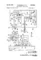
- FIG. 2 is a circuit diagram for apparatus forming one embodiment of the present invention
- FIG. 3 is a block diagram illustrating an arrangement of apparatus forming a second embodiment of the present invention:
- FIG. 4 is a circuit diagram for apparatus forming a second embodiment of the present invention.
- FIG. 5 is a rear elevational view of a striker plate assembbly forming a further aspect of the present invention.
- FIG. 6 is a section view taken along lines 66 of FIG. 5;
- FIG. 7 is a front elevational View of the striker plate assembly of FIG. 5;
- FIG. 8 is a section view taken along lines 8-8 of FIG. 6;
- FIG. 9 is a view similar to FIG. 8 but showing the various elements thereof as adjusted according to the present invention.
- FIG. 1 shows the inside doorway of a typical apartment unit set-up for protection in accordance with the present invention.
- a door casing which frames a door 22.
- a conventional knob 24 and lock arrangement 26- On the door 22 there is provided a conventional knob 24 and lock arrangement 26-.
- a special switch arrangement 28 In the casing 20, there is provided a special switch arrangement 28 to be described more fully hereinafter.
- an apartment entrance utilizing the present invention is similar to a conventional unprotected entrance.
- a wall panel 30 located on the apartment wall alongside the door casing 20.
- This wall panel is provided with an alarm speaker 32, an interior total security indicator light 34, a total security switch 36 and an emergency button 37.
- an outside alarm speaker and an exterior total security indicator light are additionally provided on the outside of the wall near the door 22.
- the switch arrangement 28 is wired to the wall panel 30 in a manner to be described hereinafter.
- the wall panel 30 in turn is connected, by means of a four wire cable 38 to a lobby control board 40.
- the lobby control board is located at a central station which is inaccessible to the public and which is always under the control of or near to a security officer such as the apartment superintendent.
- an audio alarm having a speaker 42, a panel power light 44, a panel power switch 46 and a relay reset switch 48.
- an apartment indicator light 50 there is provided an apartment indicator light 50, a lobby control light 52, an alarm light 54, a lobby control switch 56 and an audio cancel switch 58.
- the wire arrangement for the above-described system is shown in FIG. 2.
- the lock 26 as stated is bascially a conventional lock arrangement in the door 22; and it contains a latch element 60 which is retracted by turning the knob 24.
- a bolt 62 which is retracted and protracted by means of a key.
- the latch element 60 and bolt 62 each fit into a corresponding opening in a striker plate 66 mounted on the door casing 20 in alignment with the lock 26.
- the switch arrangement 28 is located inside the striker plate and it operates in conjunction with the latch element 60 and the bolt 62 to provide certain alarm indications.
- the switch arrangement 28 comprises a normally closed bolt switch 68 arranged, as shown in FIG. 2, to be opened by protracting the bolt 62 as when the door 22 is locked. Retracting the bolt 62 to unlock the door will, of course, allow the switch 68 to close.
- a normally open pressure switch 70 which is closed when lateral or door opening pressure applied to the door 22 exceeds a predetermined magnitude. The manner in which the contacts of the pressure switch 70 are closed by this lateral pressure is described in detail in copending application entitled Alarm Lock, Ser. No. 451,411, filed Apr. 28, 1965 now Pat. No. 3,284,593.
- a power source such as a battery 72.
- the positive terminal of the battery 72 is connected through the panel power switch 46 to a main fuse 74.
- the panel power light 44 is connected across the fuse 74 and battery 72 and is lit whenever the switch 46 is closed, assuming, of course, that the fuse 74 is intact and the battery 72 is furnishing power.
- the positive side of the battery 72 is thereafter connected to a B+ line 76 which extends through the lobby control board 40, the cable 38, the apartment wall panel 30 and the switch arrangement 28 at the door 22.
- the negative terminal of the battery 72 is connected to a ground line 78 which also passes through the lobby control board 40, the cable 38 and the apartment wall panel 30.
- a latching relay comprising a latching relay coil 80 and three sets of normally opened relay contacts 8183.
- the upper two of these contacts, 81 and 82, are arranged to close when the coil 80 is energized, and to connect together two sets of wires 84 and 86.
- the wires 84 and 86 form portions of the internal circuit arrangement of an electronic alarm 87; and whenever the wires in each set are connected as by energizatiton of the latching relay coil 80, the alarm 87 will be actuated.
- the lowermost contacts 83 are connected respectively to the B+ line 76 and through the coil 80 and the relay reset switch 48 to the ground line 78. It will be appreciated that once the relay coil 80 becomes energized, it closes its lowermost contact 83 to establish a closed circuit through it between the B-land ground lines 76 and 78. This self-latching effect is broken only when the reset switch 48 is opened.
- the latching relay coil 80 is energized whenever it receives B+ voltage on an alarm start line 88.
- the alarm start line extends from the coil 80 through a set of double pole switch contacts 90 controlled by an audio cancel relay coil 92 in the lobby control board 40, and through the cable 38 to the apartment wall panel 30 and the switching arrangement 28.
- the alarm start line 88 and the B+ line 76 are connected across the normally open pressure switch 70.
- the voltage on the B+ line 76 is applied to the alarm start line 88, and through it to the latching relay coil 80. This energizes the coil to close the contacts 81 and 82 and sound an alarm.
- the emergency button 37 is also connected across the alarm start line 88 and the B+ line 76, so that whenever the alarm button is pressed, contact will 'be established between the B+ and alarm lines 76 and 88 to energize the latching relay coil 80 and sound the alarm.
- a total security switch line 94 which is connected at one end 95 to the alarm line 88 in the wall panel 30.
- the total security switch line 94 then extends through the bolt switch 68 and up to a junction 96 in the wall panel 30. From the junction 96, the total security switch line 94 is connectable to the B+ line 76 in either of two ways. In the first way, it is connected through the total security switch 36' in the apartment wall panel 30. In the second way, the total security switch line 94 passes through the cable 38 to the lobby control board 40 where it passes in succession through two sets of single pole switch contacts 98 of the lobby control switch 56, and finally to the B+ line 76.
- the total security switch line 94 will be connected to the B+ line.
- the B+ line 76 can be connected to the alarm line 88 via the total security switch line 94 by allowing the bolt switch 68 to close. This, of course, can be done simply by retracting the bolt 60.
- the system will be placed on total alarm and mere retraction of the door locking bolt 68 will sufiice to sound the alarm.
- a warning light arrangement In order to indicate that the system is on total security alarm, so that an authorized person will not inadvertently start the alarm by using a key to retract the bolt 60, there is provided a warning light arrangement.
- This arrangement consists of the interior and an exterior apartment indicator light 34 and 34', the apartment indicator light 50 in the lobby control board 40 and the lobby control light 56, also in the lobby control board 40.
- the exterior and interior apartment indicator lights 34 and 34 are connected in parallel between the ground line 78 and the total security switch line 94 on the bolt switch side of the total security switch 36.
- the total security switch line 94 is connected to the B+ line 76, either through the closing of the total security switch 36 or the lobby control switch 56, both the interior and exterior apartment lights 34 and 34' will become lit.
- the apartment indicator light 50 is connected between the ground line 78 and the total security switch line 94 so that it will be placed in circuit in the same manner as the interior and exterior apartment indicator lights 34 and 34'.
- the lobby control light 52 is connected between the ground line 78 and a point along the total security switch line 94 between the two sets of double pole contacts 98 of the lobby control switch 56. The lobby control light 52 then will light only when the system is placed on total security alarm by closing of the lobby control switch 56 but not by closing of the apartment total security switch 36.
- the alarm light 54 on the lobby control panel 40 is connected between the ground line 78 and the alarm start line 88 on the cable 38 side of the switch contacts 90, so that as the alarm start line 88 receives a B+ voltage at this point, the alarm light 54 will light.
- a flasher 100 is interposed in series with the alarm light 54 for visual emphasis.
- the audio cancel relay coil 92 is connected on one side to the audio alarm start line 88 on the cable side of the switch contact 90.
- the other side of the audio cancel relay coil 92 is connected to one side of each of a pair of sets of switch terminals 93 and 95 arranged in parallel.
- the first or upper terminals 93 are normally opened and are closed by pressing the audio cancel switch 58 in the lobby control panel 40.
- the second or lower terminals 95 are also normally opened and are closed upon energization of the audio cancel relay coil 92.
- Individual interior and exterior electrically operated apartment alarms 97 may be provided at the individual apartments to broadcast through the speakers 32. These apartment alarms are each connected between the ground line 78 and the alarm start line 88.
- the overall system thus described performs a multiplicity of coordinated alarm functions.
- the system will operate, as described, to signal, at all times, any extraordinary forces tending to pry open the door 22. This takes place by closure of the pressure sensitive switch which connects the B+ line 76 and the alarm line 88.
- the B+ voltage on the alarm line 88 passes through the cable 38 to the relay coil 80 which energizes, latches itself in its energized state and holds closed the switches to the audio alarm in the lobby control panel 40.
- the alarm light 54 for the particular apartment is caused to flash.
- the total security indicator lights 34 and 34' are connected across the total security switch line 94 and the ground line 78, to light Whenever the total security switch line contains B+ voltage. Also, in the lobby control panel 40, the apartment indicator light 50 is connected across these same two lines to provide an indicator of the fact that the apartment is under total security protection. When an apartment has been placed on total security in the lobby, by throwing the switch 56, the lobby control light 52 will be turned on.
- This light however is connected to the total security switch line 94 only between the two sets of contacts 98 of the switch 56, so that the lobby control light will not turn on except by operation of this switch. This serves to indicate at the lobby control board whether the apartment was placed on total security in the apartment or at the lobby.
- the emergency button 37 may be pressed to connect the B
- the above described circuit further permits the audio alarm to be silenced once it has been sounded, without the alarm light 54 being turned oil. This is particularly advantageous for it allows the system to be reset immediately to monitor attempted illegal entry into other units or apartments, while at the time maintaining at least a visual indication of those units where trouble has occurred.
- the manner in which this occurs is as follows. First, the switch terminals 93 are closed by pressing the audio cancel switch 58. This completes a circuit to the audio cancel relay coil 92 causing its contacts to move to their upper positions so that the switch terminals 95 are closed connecting one side of the relay coil to the ground line 78 and the contacts 90 are set to connect the other side of the coil directly to the B-]- line 76.
- FIGS. 3 and 4 A somewhat modified arrangement of the invention is shown in FIGS. 3 and 4.
- a central lobby control console 200 to which are connected various groups 201 of circuit elements from each apparatusment.
- Each group consists of an interior apartment indicator panel 202 arranged on an interior apartment wall near the door, an exterior apartment panel 204 arranged outside the apartment near the door, a plurality of smoke sensors 206 and heat or fire sensors 207 distributed at strategic locations within and about the apartment and a door lock switch arrangement 208 arranged in conjunction with the door lock and striker plate assembly at the apartment.
- the door lock switch arrangement 208, the smoke and heat sensors 206 and 207, and the exterior apartment panel 204 of each group of circuit elements is connected into the associated interior apartment indicator panel 202 and this in turn is connected via a four wire cable 210 to an associated apartment panel 212 forming a portion of the lobby control console 200.
- the lobby control console 200 contains a power source, such as a battery 213 together in series with a power control switch 214 and a fuse 216.
- a power indicator light 218 is connected across the battery 212, the switch 214 and the fuse 216.
- a ground line 219 and a B-]- line 220 extend from opposite ends of the battery 212 to associated ground and 3+ connect terminals 222 and 224.
- a relay having an actuating coil 226 is arranged with the coil connected between the ground line 218 and a relay energizing terminal 228.
- the relay actuating coil 226 operates a pair of normally opened contacts 230, the closing of which connects together two sets of wires 232 for energizing an electronic alarm 233 similar to the alarm 87 of FIG. 2.
- a fire indicator light 234 and a flasher element 236 are also connected between the ground line 218 and a fire indicator connect terminal 236.
- Each apartment panel portion 212 is provided with a ground connect terminal 222A, a B+ connect terminal 224A, a relay energize connect terminal 228A and a fire indicator connect terminal 236A which are connected respectively to their counterparts in the common lobby console 200.
- a B+ line 238 and a ground line 240 extend through the apartment panel portion 212 from their respective connectors 220A and 222A; and they continue through the four wire cable 210 to the associated interior apartment indicator panel 202.
- a fire indicator line 242 extends through the apartment panel portion 212 from the fire indicator connect terminal 236 to the cable 210.
- an alarm start line 244 which extends from the relay energize connect terminal 228A through a diode 246, and through a set of normally closed double pole contacts 248 of an audio cancel relay 250 to the four wire cable 210.
- the alarm start line 244 also continues to one side of a normally open audio cancel switch 252.
- the other side of the audio cancel switch is connected to the normally open terminal of the contacts 248 and also to one side of an energizing coil 254 of the audio cancel relay 250.
- the other side of the energizing coil 254 is connected by means of a line 256 to the ground line 240.
- a reset switch 259 is connected into the 8 ground line 240 at a point near the connection to the cable 210.
- a ground line 260 Inside the apartment panel 202 there is provided a ground line 260, a B+ line 262, an alarm start line 264 and a fire indicator line 266, each connected via the cable 210 to its corresponding line in the associated apartment panel portion 212.
- a latching relay 266 comprising a coil 268, and two sets of single pole contacts 270 controlled by the coil. One side of the latching relay coil 268 is connected via a line 272 to the ground line 260.
- the other side of the coil 268 is connected to a junction 273, at which, as will be described more fully hereinafter, it receives B+ voltages upon the closure of various switches either by the smoke sensors 206 and/heat sensors 207, the door lock switching arrangement 208, or an emergency button 274 located in the interior apartment panel 202.
- the emergency button 274 operates a normally open switch, which when closed, makes a connection between the B+ line 262 and the latching relay coil 268.
- the lower of the two sets of latching relay contacts 270 when closed, completes a connection between the B+ line 262 and the junction 273 thus placing the coil 268 in circuit so that it remains latched in its energized condition.
- Closure of the lower set of contacts also serves to connect the B-I- line 262 to the alarm start line 264; and from this line it passes through the cable 210 to the alarm start line 244 in the associated apartment panel 212.
- the upper of the two sets of contacts 270 operates, when closed, to make a connection between a smoke and/or heat sensing line 276 and the fire indicator line 263.
- the smoke sensors 206 may be photoelectric transducers and the heat sensors 207 may be thermostatic elements. These sensors are set to respond to predetermined changes in ambient conditions, for example, the smoke sensors 206 will respond to predetermined amounts of smoke in the vicinity whereas the heat sensors 207 will respond to predetermined temperature levels.
- the sensor Upon responding the sensor operates to close an internal switch, thus establishing a connection between the B+ line 262 and the smoke and heat sensing line 276.
- This B-I- voltage besides being applied to the upper of the contacts 270, is also applied through a diode 278 to the junction 273 from which it operates, to energize the latching relay coil. Since energization of the coil 268 closes both sets of contacts 270, and since the sensors 206 and 207 operate to place B+ voltage on the upper of the contacts, the occurrence of a B+ voltage on the smoke an heat sensing line 276 serves to close the upper of the contacts 270 and place this voltage on the fire indicator line 263.
- the diode 278 serves to prevent the application of coil energizing voltages which are obtained by other means, such as from the door-lock switching arrangement 208 and the emergency button 274, from being also applied to the uppermost of the two sets of latching relay contacts 270, so that when the latching relay 276 becomes energized by any means other than the smoke and heat sensors 206 and 207, no B+ voltage will be applied to the fire indicator line 263.
- the door-lock switching arrangement 208 is provided with a multiplicity of switches, the first of which is a normally opened pressure sensitive switch 280. This switch operates to close a pair of contacts upon the application of any pressure against door in excess of a given amount. This switch may take the configuration described in the aforementioned copending application.
- the terminals of the pressure sensitive switch 280 are connected respectively to the B+ line 262 in the interior apartment panel 202 and to the lowermost terminal of the latching relay coil 268.
- B+ voltages will be applied to the latching relay coil 268; and, of course, will cause the coil to energize, so that a B+ voltage will be applied to the alarm start line 264 as described above.
- the door-lock switching arrangement 208 is also provided with a pair of normally closed switches 282 and 284 known, respectively, as a bolt condition switch and a total security switch. These two switches are both actuated by the door bolt; and when the bolt is protracted to lock the door, the contacts of these switches are opened.
- the terminals of the bolt condition switch 282 are connected respectively to the B+ line 262 and through a volt condition indicator light 284 to the ground line 260.
- the contacts of the bolt condition switch 282 become closed. This serves to connect the bolt indicator light 284 across the B+ line 262 and the ground line 260. The bolt indicator light is thus turned on to indicate that the bolt has been retracted.
- the terminals of the total security switch 284 are connected respectively between a total security line 288 and the junction 273. Whenever a B+ potential exists upon the total security line 288, closing of the total security switch 286 by retraction of the bolt will apply this B+ potential to the latching relay coil, causing a B+ voltage to appear on the alarm start line 264.
- the application of B+ voltage to the total security line 288 occurs as a result of closing a total security set switch 290, the termirials of which are connected respectively to the B+ line 262 and to the total security line 288.
- the closing of this switch also places a total security indicator light into circuit between the B+ line 262 and between the ground line 260, so that when the total security set switch 290 is thrown to its uppermost position to apply B+ voltage to the total security line 288, the total security indicator light 292 is turned on.
- the exterior apartment panel 204 contains an exterior total security indicator light 294 and a key operated total security set switch 296.
- the exterior total security indicator light 294 is connected between the ground line 260 in the interior apartment panel 202 and between the total security line 288 in the interior apartment panel.
- the key operated total security set switch 296 includes a movable contact 298 which is connected to the B+ line 262 in the interior apartment panel and which may be moved by means of a special key to make contact with the total security line 288. Whenever the movable contact 298 is moved to its on position, as indicated in the drawing, B+ voltage will be applied to the total security line 288 to allow the total security switch 286 in the door-lock switching arrangement to operate as above described.
- this movement of the movable contact 298 places the exterior security indicator light 294 into circuit between the B+ line 262 and the ground line 260 'so that this light will also indicate that the apartment has been placed on total security condition and that movement of the bolt in the door-lock switching arrangement will cause energization of the latching relay 266 and the placement of a B+ voltage on the alarm start line 264.
- the above-described system involves a number of phases of operation.
- an alarm is sounded whenever the emergency button 274 on the interior apartment panel 202 is pushed.
- pushing of this button closes a connection between the B+ line 262 and the junction 273 leading to the coil 268 of the latching relay 266.
- This energizes the coil so that its switch elements 270 close to place a B+ potential on the alarm start line 264.
- This B+ potential is conveyed through the cable 210 through the alarm start line 244 in the associated apartment panel 212 in the lobby control console 200.
- the bolt condition indicator light 284 is not lit then the bolt has been protracted and it is then possible to close the total security set switch 290 without the alarm being sounded.
- the interior total security indicator light 292 goes on to indicate to the person in the apartment that if the bolt is not thrown or retracted, as in unlocking the door, the alarm Will be actuated. When this light is on therefore the person should first of all throw the total security set switch 290' to take the apartment off the total security alarm before retracting the bolt to open the door.
- a special key may be used to move the movable contact 298 of the switch 296 to place the apartment on total security alarm.
- both the interior total security indicator light and the exterior total security indicator light 294 are connected across the ground line 260 and the B+ line 262 are therefore turned on to indicate to persons both outside and inside the apartment that unless the apartment is first taken off of total security alarm any retraction of the door bolt will cause an alarm to be set off.
- This arrangement serves to protect the apartment at certain times from persons who may have obtained a key in an illegal manner or who may be competent at manipulating certain door locks.
- an alarm is set oif upon the occurrence of smoke or fire at certain places in and about the apartment. As described above, this is accomplished by means of the smoke and heat sensors 206 and 207 which close switches to connect the B-lline 2.62 to the smoke and heat sensor line 276, when preset conditions of smoke density and/or temperature in the apartment are exceeded. Since the smoke and heat sensor line 276 is connected via the junction 273 to the relay coil 266, the application of B+ voltage to this line by the smoke and heat sensors 206 and 207, serves to energize and latch the relay and this produces a signal on the alarm line 264.
- a 3+ voltage is connected through the now closed upper of the contacts 270 to the fire indicator line 263; and this B+ voltage is applied through the cable 210 to the fire indicator line 242 in the associated apartment panel 212.
- This B+ voltage then passes through a flasher element 236 to cause the fire indicator light 234 in the lobby console 200 to flash intermittently.
- the arrangement of the present invention permits the building superintendent or person in charge of the lobby control console 200 to stop the audio alarm while maintaining the visual alarm light 258 in operation. This permits the system to monitor other apartments or units within the building while still maintaining at least a visual indication of the particular apartment in which trouble has occurred. This is accomplished by pressing the audio cancel switch 252 which places the B+ voltage from the alarm start line 244 onto the energizing coil 254. Energization of this coil brings the movable element of the switch contacts 248 to an upper position. The energizing coil 254 is then latched in place so that no voltage now can proceed down via the diode 246, the relay energized connecting terminals 228 to the actuating coil 226. The actuating coil 226 is then de-energized and the switch contacts 230 fall to their normal position and disconnect the sets of wires 232 from each other to stop the alarm.
- FIGS. 5-9 show a striker plate assembly which is particularly advantageous in operating the door-lock switching arrangements of the present invention.
- a fiat rectangular striker plate 300 having screw holes 301 at either end for attaching the plate to a door casing.
- the striker plate 300 is also formed with an elongated rectangular opening 302 (FIG. 7) which accommodates the bolt and latch of a door-lock mechanism.
- a pair of side plates 304 extend rearwardly of the striker plate on either side of the opening 302.
- a normally open pressure switch 306 and a magnetically actuable reed switch 308 having normally closed contacts 309 are attached to the outer portions of the side plates 304.
- FIG. 7 shows a striker plate assembly which is particularly advantageous in operating the door-lock switching arrangements of the present invention.
- FIG. 7 there is provided a fiat rectangular striker plate 300, having screw holes 301 at either end for attaching the plate to a door casing.
- the striker plate 300 is also formed with an elongated
- a door-lock assembly 310 becomes aligned with the striker plate 300 upon closure of an apartment door.
- the doorlock assembly includes a bolt 312 (shown in dotted out line) and a latch 314 (also shown in dotted outline) which project from the lock assembly 310 and enter into the opening 302 in the striker plate 300.
- the bolt 312 has embedded therein a cylindrical magnet 316 which, when the bolt 312 is projected, as shown in FIG. 6, comes into proximity with the magnetically actuable reed switch 308.
- the magnetic field of the magnet 316 surrounds the reed switch 308 when the bolt 312 is projected, and thus acts to open the normally closed contacts 309 of the switch.
- the initial position of the pressure arm 328 can be adjusted by turning the screws 330 and 332 to adjust the initial position of the outer end of the pressure arm 328.
- This enables the device to be adjusted to accommodate bolts of different widths say from of an inch to /2 of an inch by a very simple adjustment.
- the initial tension of the spring 334 can be adjusted so that the amount of pressure needed to pivot the pressure member 326 about the fulcrum plates 318 and 320 may also be adjusted.
- the switch 306 is positioned such that pivoting of the pressure member 326 will cause the switch to close. This, of course, will close a circuit such as described in the two systems described above to sound an alarm.
- an alarm system arranged to proteet an enclosure secured by a door
- lock means for locking said door
- first switch means arranged to be actuated only by attempts to open said door without proper operation of said lock means
- second switch means arranged to be actuated only by proper operation of said lock means
- an electrically actuated alarm arranged in circuit with said first and second switch means to be put into operation upon actuation of either of said switch means
- further total security switch means located within said enclosure and arranged in circuit relationship with said second switch means to control'its ability to operate said alarm
- indicator means arranged outside said enclosure to indicate the condition of said total security switch means.
- lock means comprises a bolt associated with said closure and reciprocally movable between closure locking and unlocking positions and arranged to operate said second switch means upon such reciprocal movement.
- An alarm system including additional alarm actuating switch means being operative in response to other alarm conditions to actuate said alarm, said additional alarm actuation switch means being connected to actuate said alarm independently of said total security switch.
- said central control panel includes individual visual indicators wired into associated ones of said individual electrical circuits to be actuated by the sen-sing switch means thereof, said central control panel further including a common audio indicator wired to be actuated upon actuation of any one of said sensing switch means, first electrical latching means arranged to maintain actuation of each individual visual indicator, second electrical latching means arranged to maintain actuation of said common audio indicator following actuation thereof, and an audio indicator cancel switch means arranged to release said second electrical latching means of said audio indicator without affecting said first latching means, said audio indicator cancel switch means further being arranged to permit subsequent actuation of said audio indicator upon subsequent electrical switch means actuation by one of said sensing switch means.
- a door a door casing, a retractable bolt on said door for projecting into said casing, a striker plate assembly on said casing for receiving said bolt, said striker plate assembly including a pair of apexed fulcrum elements which extend rearwardly above and below said bolt, said striker plate assembly further including a pressure member which extends alongside the projected bolt, said pressure member being formed with a flat rocker surface which rocks about said fulcrum elements and a pressure surface which extends out from said rocker surface alongside said bolt, resilient bias means arranged to oppose rocking movement of said pressure member in response to forces less than a predetermined magnitude applied thereagainst by said bolt, and an alarm system including switch means arranged to actuate an alarm upon rocking movement of said pressure member.
- rocker surface is secured to said fulcrum elements by means of bolts extending through holes in said rocker surface and threaded into said fulcrum elements on opposite sides, respectively, of their apexes.
Description
P. M. HAWKINS E AL 3,537,094
SBheets-Sheet 1 INVENTORS 3w;- Mnomov Hnwxms BY JOSEPH L. Man/0611 1 FJRELAESU' Amen SHOTOFF f TOTAL SECURITY ALARM SYSTEM 3 MH HH MNWHI HH IHHHnuuulunk.
Oct. 27,1970
Original Fi led Jan. 24, 1966 I Loeev Mmo mm UGHT .Swncn mm" A l-Q Get. 27, 19-70 I g, H NS ETAL 3,531,094
TOTAL SECURITY ALARM SYSTEM.
5 Sheets-Sheet 2 Original Filed Jan. 24. 1966 INVENTORS Pew. Mano/sew Haw/M BY Joseph L- Mnmxun flqmca w aw Oct. 27, 1 970 P. M.-HAWKINS T 3,537,094
7 TOTAL SECURITY ALARM SYSTEM Original Filed Jan. 24, 1966 5 SheetS -Sheet 5 A llll ZOb Loeay Con/ma Con/604E Paw Mano/sou Haw/was BY JOSEPH L- M19005)? INVENTORS Anne/v0.51
a, rmyyxms ETAL 3,537,094
ITOTAL SECURITY ALARM SYSTEM Original Filed Jan. 24, 1966 7 Oct. 27, 1970 5 Sheets-Sheet 4 INVENTORS 1 90:. #7900160 I/qwxms By d scfiw L Mmrocun 8N ovw Oct. 27, 1970 P. M. HAWKINS ET AL I 3,537,094
TOTAL SECURITY ALARM SYSTEM Original Filed Jan. 24, 1966 5 Sheets-Sheet 5 -HIII III[II'IHI mm Wil INVENTORB 9 Mqoasou Hawk/N BY Jase?" "M 0&0;
M Maggie 3,537,094 TOTAL SECURITY ALARM SYSTEM Paul Maddison Hawkins and Joseph L. Mandella, Jericho, N.Y., assignors to General Alarm Corporation, New York, N.Y., a corporation of Delaware Continuation of application Ser. No. 522,635, Jan. 24, 1966. This application May 16, 1969, Ser. No. 827,108 Int. Cl. G08b 13/06, 13/08 US. Cl. 340-274 15 Claims ABSTRACT OF THE DISCLOSURE An electrically actuated alarm system which includes sensing switch means connected in circuit with an alarm to actuate the alarm upon certain attempted opening movements of a closure, and total security switch means for rendering efiective the first switch means and a warning indicator arrangement actuated by the operation of the total security switch means.
This is a continuation of application 522,635 filed Jan. 24, 1966, now abandoned.
This invention relates to the protection of closures and more particularly it concerns a total security alarm system for use in connection with dwellings of various types.
The problem of protecting against unauthorized and illegal entry into dwellings has been particularly difiicult to solve; one reason being that any technique which rendered unauthorized entry more difficult also made authorized entry more difficult. Also, most prior attempted solutions to the problem resulted in inordinately elaborate locking mechanisms which were prohibitively expensive.
The problem of security becomes especially acute in connection with large multi-unit dwellings such as apartment houses. Because of the large numbers required, the locks-on the individual units should be inexpensive. Yet, because of the large number of closely spaced dwellings, an apartment building presents an inviting target for a would-be thief. For this reason, it has been necessary to resort to the expensive and often inefiicient practice of maintaining a patrol in and about the area of the apartment building.
The present invention provides a means for overcoming the above-described problems. With the present invention, a dwelling or any other enclosed region having a closeable entrance-way may be protected efiiciently and with a minimum of expense. Furthermore, no patrolling guards are required for the invention makes possible a remote indication of any unauthorized entry or attempted entry. Another feature of the present invention is that it gives a positive indication at the entrance-way that the enclosure or dwelling being protected is under total security protection. This unsually serves to thwart any planned invasion of the dwelling even before it commences.
It is an especially important feature of the present invention that the actual door locking mechanism of an entrance-way being protected may be left essentially unchanged. The ability of the invention to protect against unauthorized invasion is completely independent of the efliciency or strength of the actual locking mechanism. Furthermore, in one of its aspects, the invention serves to provide remote advance notification of an attempted illegal entry so that steps may be taken to apprehend the intruder before he can escape or consummate the illegal entry. A
Basically, the present invention makes use of an electronically actuated alarm, an electrical power source and an electrical network which includes novel switching arrangements for placing the alarm in circuit with the power source at selected times. The switching arrangements as- United States Patent sociated with the electrical network are arranged in part to be actuated by a change of condition at the closure or door of the enclosure being protected. There are two such switches on each door. The first switch is of the pressure sensitive variety and is closed when the pressure against the door exceeds an amount greater than that usually associated with inadvertent bumping, but less than the amount needed to pry the door open. The second switch is of the condition responsive variety and it operates to close the alarm network whenever a latch or bolt in the door is retracted. The second switch thus provides total security protection against those would-be intruders who might have sufficient expertise to manipulate the lock on the door. Additional manually operable switch means are provided to render the second switch ineifective at certain times as when authorized entry is to be made. These additional switch means may comprise switches located within the dwelling to be actuated by a person inside; and they may additionally comprise outside switches located either at a remote control panel or immediately outside the protected door and arranged to be thrown by means of a special key.
The electrical network of the present invention is especially suited for multi-unit protection wherein an alarm will be sounded at a central station whenever any of a number of protected units or apartments is being invaded. This network, besides providing connection to actuate a central alarm, also serves to indicate the particular unit involved. Moreover, the central alarm may be reset immediately so that the system will monitor possible further intrusions of other units; yet the indication of the first unit aifected is maintained until after an investigation of that unit has been made.
In addition to providing the above information, the system of the present invention is capable of automatically signalling at a central station, the onset of fire or excessive heat or smoke in any unit. Further, the system makes provision for the use of emergency buttons which may be strategically located in or about the dwelling or unit to protect against personal invasion or assault.
In another aspect, the present invention makes special provision for a unique door switching arrangement in which there is provided a special type striker plate assembly which produces positive and accurate switching when lateral bolt or latch pressure exceeds a given amount. In this novel striker plate assembly, adjustment may be made conveniently for various bolt or latch widths so that the striker plate may be adapted for use with any of several types of door lock. Also, the pressure setting necessary to cause switching may be adjusted with ease.
Basically, this novel striker plate assembly comprises a pair of rounded tapered fulcrum plates about which one flat rectangular arm of a pressure member can rock. The pressure member has another arm extending out at an angle from the first arm and this second arm is located parallel and close to one longitudinal edge of a striker plate bolt and latch opening. Each fulcrum plate has a threaded opening on each side of its fulcrum point and bolts or screws passing through enlarged holes in the first arm of the pressure member are threaded into these openings. A compression spring is provided between the bolt head and the pressure element on the other arm side of the fulcrum. By adjusting the spring bolt in its threaded opening, the spring tension and therefore the pressure necessary to cause switching may be varied. By adjusting the other bolt, the initial position of the other arm of the pressure element may be varied so that the assembly may be fitted to accommodate different bolt widths. Switch means, of course, are provided to close or open contacts upon rocking of the pressure element about the fulcrum plates as a door bolt forces against its other arm.
There has thus been outlined rather broadly the more important features of the invention in order that the detailed description thereof that follows may be better understood, and in order that the present contribution to the art may be better appreciated. There are, of course, additional features of the invention that will be described hereinafter and which will form the subject of the claims appended hereto. Those skilled in the art will appreciate that the conception upon which this disclosure is based may be readily be utilized as a basis for the designing of other structures for carrying out the several purposes of the invention. It is important, therefore, that the claims be regarded as including such equivalent constructions as do not depart from the spirit and scope of the invention.
Specific embodiments of the invention have been chosen for purposes of illustration and description and are shown in the accompanying drawings forming a part of the specification, wherein:
FIG. 1 is a fragmentary representation of pertinent portions of a dwelling arranged to be protected by the present invention;
FIG. 2 is a circuit diagram for apparatus forming one embodiment of the present invention;
FIG. 3 is a block diagram illustrating an arrangement of apparatus forming a second embodiment of the present invention:
FIG. 4 is a circuit diagram for apparatus forming a second embodiment of the present invention;
FIG. 5 is a rear elevational view of a striker plate assembbly forming a further aspect of the present invention;
FIG. 6 is a section view taken along lines 66 of FIG. 5;
FIG. 7 is a front elevational View of the striker plate assembly of FIG. 5;
FIG. 8 is a section view taken along lines 8-8 of FIG. 6; and
FIG. 9 is a view similar to FIG. 8 but showing the various elements thereof as adjusted according to the present invention.
FIG. 1 shows the inside doorway of a typical apartment unit set-up for protection in accordance with the present invention. As shown, there is a door casing which frames a door 22. On the door 22 there is provided a conventional knob 24 and lock arrangement 26-. In the casing 20, there is provided a special switch arrangement 28 to be described more fully hereinafter.
Externally, the appearance of an apartment entrance utilizing the present invention is similar to a conventional unprotected entrance. There is, however, a wall panel 30 located on the apartment wall alongside the door casing 20. This wall panel is provided with an alarm speaker 32, an interior total security indicator light 34, a total security switch 36 and an emergency button 37. There is additionally provided an outside alarm speaker and an exterior total security indicator light on the outside of the wall near the door 22.
The switch arrangement 28 is wired to the wall panel 30 in a manner to be described hereinafter. The wall panel 30 in turn is connected, by means of a four wire cable 38 to a lobby control board 40. The lobby control board is located at a central station which is inaccessible to the public and which is always under the control of or near to a security officer such as the apartment superintendent.
On the lobby control board 40, there is provided an audio alarm having a speaker 42, a panel power light 44, a panel power switch 46 and a relay reset switch 48. There are also provided several groups of lights and switches, each group being identified by the number of a particular apartment with which it corresponds, such as apartment 100, 101 etc. In each group, there is provided an apartment indicator light 50, a lobby control light 52, an alarm light 54, a lobby control switch 56 and an audio cancel switch 58.
The wire arrangement for the above-described system is shown in FIG. 2. The lock 26 as stated is bascially a conventional lock arrangement in the door 22; and it contains a latch element 60 which is retracted by turning the knob 24. There is also provided a bolt 62 which is retracted and protracted by means of a key. The latch element 60 and bolt 62 each fit into a corresponding opening in a striker plate 66 mounted on the door casing 20 in alignment with the lock 26. The switch arrangement 28 is located inside the striker plate and it operates in conjunction with the latch element 60 and the bolt 62 to provide certain alarm indications.
More specifically, the switch arrangement 28 comprises a normally closed bolt switch 68 arranged, as shown in FIG. 2, to be opened by protracting the bolt 62 as when the door 22 is locked. Retracting the bolt 62 to unlock the door will, of course, allow the switch 68 to close. There is additionally provided a normally open pressure switch 70 which is closed when lateral or door opening pressure applied to the door 22 exceeds a predetermined magnitude. The manner in which the contacts of the pressure switch 70 are closed by this lateral pressure is described in detail in copending application entitled Alarm Lock, Ser. No. 451,411, filed Apr. 28, 1965 now Pat. No. 3,284,593.
Turning now to the wiring arrangement in the lobby control board 40, there is provided a power source such as a battery 72. The positive terminal of the battery 72 is connected through the panel power switch 46 to a main fuse 74. The panel power light 44 is connected across the fuse 74 and battery 72 and is lit whenever the switch 46 is closed, assuming, of course, that the fuse 74 is intact and the battery 72 is furnishing power. The positive side of the battery 72 is thereafter connected to a B+ line 76 which extends through the lobby control board 40, the cable 38, the apartment wall panel 30 and the switch arrangement 28 at the door 22. The negative terminal of the battery 72 is connected to a ground line 78 which also passes through the lobby control board 40, the cable 38 and the apartment wall panel 30.
Also provided in the lobby control board 40 is a latching relay comprising a latching relay coil 80 and three sets of normally opened relay contacts 8183. The upper two of these contacts, 81 and 82, are arranged to close when the coil 80 is energized, and to connect together two sets of wires 84 and 86. The wires 84 and 86 form portions of the internal circuit arrangement of an electronic alarm 87; and whenever the wires in each set are connected as by energizatiton of the latching relay coil 80, the alarm 87 will be actuated.
The lowermost contacts 83, are connected respectively to the B+ line 76 and through the coil 80 and the relay reset switch 48 to the ground line 78. It will be appreciated that once the relay coil 80 becomes energized, it closes its lowermost contact 83 to establish a closed circuit through it between the B-land ground lines 76 and 78. This self-latching effect is broken only when the reset switch 48 is opened.
The latching relay coil 80 is energized whenever it receives B+ voltage on an alarm start line 88. The alarm start line extends from the coil 80 through a set of double pole switch contacts 90 controlled by an audio cancel relay coil 92 in the lobby control board 40, and through the cable 38 to the apartment wall panel 30 and the switching arrangement 28.
In the switching arrangement 28, the alarm start line 88 and the B+ line 76 are connected across the normally open pressure switch 70. Thus whenever this switch is closed, as by applying pressure to the door 22, the voltage on the B+ line 76 is applied to the alarm start line 88, and through it to the latching relay coil 80. This energizes the coil to close the contacts 81 and 82 and sound an alarm.
In the apartment wall panel 30, the emergency button 37 is also connected across the alarm start line 88 and the B+ line 76, so that whenever the alarm button is pressed, contact will 'be established between the B+ and alarm lines 76 and 88 to energize the latching relay coil 80 and sound the alarm.
There is additionally provided a total security switch line 94 which is connected at one end 95 to the alarm line 88 in the wall panel 30. The total security switch line 94 then extends through the bolt switch 68 and up to a junction 96 in the wall panel 30. From the junction 96, the total security switch line 94 is connectable to the B+ line 76 in either of two ways. In the first way, it is connected through the total security switch 36' in the apartment wall panel 30. In the second way, the total security switch line 94 passes through the cable 38 to the lobby control board 40 where it passes in succession through two sets of single pole switch contacts 98 of the lobby control switch 56, and finally to the B+ line 76. Thus Whenever either the total security switch 36 in the apartment or the lobby control switch A 56 at the lobby control board 40' is closed, then the total security switch line 94 will be connected to the B+ line. In such situation, the B+ line 76 can be connected to the alarm line 88 via the total security switch line 94 by allowing the bolt switch 68 to close. This, of course, can be done simply by retracting the bolt 60. Thus whenever the total security switch 36 or the lobby control switch is closed, the system will be placed on total alarm and mere retraction of the door locking bolt 68 will sufiice to sound the alarm.
In order to indicate that the system is on total security alarm, so that an authorized person will not inadvertently start the alarm by using a key to retract the bolt 60, there is provided a warning light arrangement. This arrangement consists of the interior and an exterior apartment indicator light 34 and 34', the apartment indicator light 50 in the lobby control board 40 and the lobby control light 56, also in the lobby control board 40. The exterior and interior apartment indicator lights 34 and 34 are connected in parallel between the ground line 78 and the total security switch line 94 on the bolt switch side of the total security switch 36. Thus whenever the total security switch line 94 is connected to the B+ line 76, either through the closing of the total security switch 36 or the lobby control switch 56, both the interior and exterior apartment lights 34 and 34' will become lit.
Also, at the lobby control board 40, the apartment indicator light 50 is connected between the ground line 78 and the total security switch line 94 so that it will be placed in circuit in the same manner as the interior and exterior apartment indicator lights 34 and 34'. The lobby control light 52 is connected between the ground line 78 and a point along the total security switch line 94 between the two sets of double pole contacts 98 of the lobby control switch 56. The lobby control light 52 then will light only when the system is placed on total security alarm by closing of the lobby control switch 56 but not by closing of the apartment total security switch 36.
The alarm light 54 on the lobby control panel 40 is connected between the ground line 78 and the alarm start line 88 on the cable 38 side of the switch contacts 90, so that as the alarm start line 88 receives a B+ voltage at this point, the alarm light 54 will light. A flasher 100 is interposed in series with the alarm light 54 for visual emphasis.
The audio cancel relay coil 92 is connected on one side to the audio alarm start line 88 on the cable side of the switch contact 90. The other side of the audio cancel relay coil 92 is connected to one side of each of a pair of sets of switch terminals 93 and 95 arranged in parallel. The first or upper terminals 93 are normally opened and are closed by pressing the audio cancel switch 58 in the lobby control panel 40. The second or lower terminals 95 are also normally opened and are closed upon energization of the audio cancel relay coil 92.
Individual interior and exterior electrically operated apartment alarms 97 may be provided at the individual apartments to broadcast through the speakers 32. These apartment alarms are each connected between the ground line 78 and the alarm start line 88.
The overall system thus described performs a multiplicity of coordinated alarm functions. In the first place, the system will operate, as described, to signal, at all times, any extraordinary forces tending to pry open the door 22. This takes place by closure of the pressure sensitive switch which connects the B+ line 76 and the alarm line 88. The B+ voltage on the alarm line 88 passes through the cable 38 to the relay coil 80 which energizes, latches itself in its energized state and holds closed the switches to the audio alarm in the lobby control panel 40. At the same time, the alarm light 54 for the particular apartment is caused to flash.
Whenever the system is placed on total security alarm as by closing either the total security switch 36 in the apartment or the lobby control switch 56 at the lobby control board 40, the alarm will sound even when a key is used to enter the apartment. This is because the bolt switch 68 closes upon retraction of the bolt 62, irrespective of what means are used to retract it. Closure of this switch acts, when the system is set for total security, to connect the total security switch line 94 (containing B+ voltage) to alarm start line 88; and this serves, as above described, to sound an alarm. This total security arrangement provides double safety against persons who are expert lock manipulators or persons who may have illegally obtained a key.
To place an apartment on total security it is only necessary to connect the total security switch line 94 to the B+ line 76. This may be done either inside the apartment by closing the total security switch 36, or inthe lobby by setting the lobby control switch 56.
It is, of course, desirable to know whether the apartment has been placed on total security alarm in order that the bolt 62 will not be retracted inadvertently by an authorized person to cause a false alarm. For this reason, the total security indicator lights 34 and 34' are connected across the total security switch line 94 and the ground line 78, to light Whenever the total security switch line contains B+ voltage. Also, in the lobby control panel 40, the apartment indicator light 50 is connected across these same two lines to provide an indicator of the fact that the apartment is under total security protection. When an apartment has been placed on total security in the lobby, by throwing the switch 56, the lobby control light 52 will be turned on. This light however is connected to the total security switch line 94 only between the two sets of contacts 98 of the switch 56, so that the lobby control light will not turn on except by operation of this switch. This serves to indicate at the lobby control board whether the apartment was placed on total security in the apartment or at the lobby.
In addition to the above, the emergency button 37 may be pressed to connect the B| line 76 to the alarm start line 88 to sound the alarm as above described in the event that what at first appears to be a desired guest turns out to be an intruder.
The above described circuit further permits the audio alarm to be silenced once it has been sounded, without the alarm light 54 being turned oil. This is particularly advantageous for it allows the system to be reset immediately to monitor attempted illegal entry into other units or apartments, while at the time maintaining at least a visual indication of those units where trouble has occurred. The manner in which this occurs is as follows. First, the switch terminals 93 are closed by pressing the audio cancel switch 58. This completes a circuit to the audio cancel relay coil 92 causing its contacts to move to their upper positions so that the switch terminals 95 are closed connecting one side of the relay coil to the ground line 78 and the contacts 90 are set to connect the other side of the coil directly to the B-]- line 76. This completes a circuit to the coil 92 and latches it in its energized condition. At the same time, B+ potential continues to be supplied via the flasher 100 to the alarm light 54. The alarm start line 88 however is broken, at the contacts 90, from the audio relay coil 80 so that the relay when de-energized by pressing the reset switch 48 will not become re-energized by any continuing voltage on the alarm start line 88 when the switch 48 is relaesed.
A somewhat modified arrangement of the invention is shown in FIGS. 3 and 4. In the block diagram of FIG. 3, there is shown a central lobby control console 200 to which are connected various groups 201 of circuit elements from each aparatment. Each group consists of an interior apartment indicator panel 202 arranged on an interior apartment wall near the door, an exterior apartment panel 204 arranged outside the apartment near the door, a plurality of smoke sensors 206 and heat or fire sensors 207 distributed at strategic locations within and about the apartment and a door lock switch arrangement 208 arranged in conjunction with the door lock and striker plate assembly at the apartment. The door lock switch arrangement 208, the smoke and heat sensors 206 and 207, and the exterior apartment panel 204 of each group of circuit elements is connected into the associated interior apartment indicator panel 202 and this in turn is connected via a four wire cable 210 to an associated apartment panel 212 forming a portion of the lobby control console 200.
The lobby control console 200, as shown in FIG. 4, contains a power source, such as a battery 213 together in series with a power control switch 214 and a fuse 216. A power indicator light 218 is connected across the battery 212, the switch 214 and the fuse 216. A ground line 219 and a B-]- line 220 extend from opposite ends of the battery 212 to associated ground and 3+ connect terminals 222 and 224. Similarly a relay having an actuating coil 226 is arranged with the coil connected between the ground line 218 and a relay energizing terminal 228. The relay actuating coil 226 operates a pair of normally opened contacts 230, the closing of which connects together two sets of wires 232 for energizing an electronic alarm 233 similar to the alarm 87 of FIG. 2. A fire indicator light 234 and a flasher element 236 are also connected between the ground line 218 and a fire indicator connect terminal 236.
Each apartment panel portion 212 is provided with a ground connect terminal 222A, a B+ connect terminal 224A, a relay energize connect terminal 228A and a fire indicator connect terminal 236A which are connected respectively to their counterparts in the common lobby console 200. A B+ line 238 and a ground line 240 extend through the apartment panel portion 212 from their respective connectors 220A and 222A; and they continue through the four wire cable 210 to the associated interior apartment indicator panel 202. Also, a fire indicator line 242 extends through the apartment panel portion 212 from the fire indicator connect terminal 236 to the cable 210. There is additionally provided an alarm start line 244 which extends from the relay energize connect terminal 228A through a diode 246, and through a set of normally closed double pole contacts 248 of an audio cancel relay 250 to the four wire cable 210.
The alarm start line 244 also continues to one side of a normally open audio cancel switch 252. The other side of the audio cancel switch is connected to the normally open terminal of the contacts 248 and also to one side of an energizing coil 254 of the audio cancel relay 250. The other side of the energizing coil 254 is connected by means of a line 256 to the ground line 240. There is additionally provided a visual alarm light 258 which is connected between the ground line 240 and the alarm start line 244. A reset switch 259 is connected into the 8 ground line 240 at a point near the connection to the cable 210.
Inside the apartment panel 202 there is provided a ground line 260, a B+ line 262, an alarm start line 264 and a fire indicator line 266, each connected via the cable 210 to its corresponding line in the associated apartment panel portion 212. Inside the interior of apartment panel 202 there is provided a latching relay 266 comprising a coil 268, and two sets of single pole contacts 270 controlled by the coil. One side of the latching relay coil 268 is connected via a line 272 to the ground line 260. The other side of the coil 268 is connected to a junction 273, at which, as will be described more fully hereinafter, it receives B+ voltages upon the closure of various switches either by the smoke sensors 206 and/heat sensors 207, the door lock switching arrangement 208, or an emergency button 274 located in the interior apartment panel 202. As shown, the emergency button 274 operates a normally open switch, which when closed, makes a connection between the B+ line 262 and the latching relay coil 268. The lower of the two sets of latching relay contacts 270, when closed, completes a connection between the B+ line 262 and the junction 273 thus placing the coil 268 in circuit so that it remains latched in its energized condition. Closure of the lower set of contacts also serves to connect the B-I- line 262 to the alarm start line 264; and from this line it passes through the cable 210 to the alarm start line 244 in the associated apartment panel 212. The upper of the two sets of contacts 270 operates, when closed, to make a connection between a smoke and/or heat sensing line 276 and the fire indicator line 263. The smoke sensors 206 may be photoelectric transducers and the heat sensors 207 may be thermostatic elements. These sensors are set to respond to predetermined changes in ambient conditions, for example, the smoke sensors 206 will respond to predetermined amounts of smoke in the vicinity whereas the heat sensors 207 will respond to predetermined temperature levels. Upon responding the sensor operates to close an internal switch, thus establishing a connection between the B+ line 262 and the smoke and heat sensing line 276. This B-I- voltage, besides being applied to the upper of the contacts 270, is also applied through a diode 278 to the junction 273 from which it operates, to energize the latching relay coil. Since energization of the coil 268 closes both sets of contacts 270, and since the sensors 206 and 207 operate to place B+ voltage on the upper of the contacts, the occurrence of a B+ voltage on the smoke an heat sensing line 276 serves to close the upper of the contacts 270 and place this voltage on the fire indicator line 263. The diode 278 serves to prevent the application of coil energizing voltages which are obtained by other means, such as from the door-lock switching arrangement 208 and the emergency button 274, from being also applied to the uppermost of the two sets of latching relay contacts 270, so that when the latching relay 276 becomes energized by any means other than the smoke and heat sensors 206 and 207, no B+ voltage will be applied to the fire indicator line 263.
The door-lock switching arrangement 208 is provided with a multiplicity of switches, the first of which is a normally opened pressure sensitive switch 280. This switch operates to close a pair of contacts upon the application of any pressure against door in excess of a given amount. This switch may take the configuration described in the aforementioned copending application. The terminals of the pressure sensitive switch 280 are connected respectively to the B+ line 262 in the interior apartment panel 202 and to the lowermost terminal of the latching relay coil 268. Thus, whenever a force is applied to the door of sutficient magnitude to cause the pressure sensitive switch 280 to close, B+ voltages will be applied to the latching relay coil 268; and, of course, will cause the coil to energize, so that a B+ voltage will be applied to the alarm start line 264 as described above.
The door-lock switching arrangement 208 is also provided with a pair of normally closed switches 282 and 284 known, respectively, as a bolt condition switch and a total security switch. These two switches are both actuated by the door bolt; and when the bolt is protracted to lock the door, the contacts of these switches are opened. The terminals of the bolt condition switch 282 are connected respectively to the B+ line 262 and through a volt condition indicator light 284 to the ground line 260. Thus, Whenever the bolt is retracted or in condition so that the door can be opened, the contacts of the bolt condition switch 282 become closed. This serves to connect the bolt indicator light 284 across the B+ line 262 and the ground line 260. The bolt indicator light is thus turned on to indicate that the bolt has been retracted.
The terminals of the total security switch 284 are connected respectively between a total security line 288 and the junction 273. Whenever a B+ potential exists upon the total security line 288, closing of the total security switch 286 by retraction of the bolt will apply this B+ potential to the latching relay coil, causing a B+ voltage to appear on the alarm start line 264. The application of B+ voltage to the total security line 288 occurs as a result of closing a total security set switch 290, the termirials of which are connected respectively to the B+ line 262 and to the total security line 288. The closing of this switch also places a total security indicator light into circuit between the B+ line 262 and between the ground line 260, so that when the total security set switch 290 is thrown to its uppermost position to apply B+ voltage to the total security line 288, the total security indicator light 292 is turned on.
The exterior apartment panel 204 contains an exterior total security indicator light 294 and a key operated total security set switch 296. The exterior total security indicator light 294 is connected between the ground line 260 in the interior apartment panel 202 and between the total security line 288 in the interior apartment panel. The key operated total security set switch 296 includes a movable contact 298 which is connected to the B+ line 262 in the interior apartment panel and which may be moved by means of a special key to make contact with the total security line 288. Whenever the movable contact 298 is moved to its on position, as indicated in the drawing, B+ voltage will be applied to the total security line 288 to allow the total security switch 286 in the door-lock switching arrangement to operate as above described. Also, this movement of the movable contact 298 places the exterior security indicator light 294 into circuit between the B+ line 262 and the ground line 260 'so that this light will also indicate that the apartment has been placed on total security condition and that movement of the bolt in the door-lock switching arrangement will cause energization of the latching relay 266 and the placement of a B+ voltage on the alarm start line 264.
The above-described system, like the system of FIGS. 1 and 2, involves a number of phases of operation. In the first phase, an alarm is sounded whenever the emergency button 274 on the interior apartment panel 202 is pushed. As described above, pushing of this button closes a connection between the B+ line 262 and the junction 273 leading to the coil 268 of the latching relay 266. This energizes the coil so that its switch elements 270 close to place a B+ potential on the alarm start line 264. This B+ potential is conveyed through the cable 210 through the alarm start line 244 in the associated apartment panel 212 in the lobby control console 200. This voltage passes down through the contacts 248, the diode 246 and the relay energize connection terminals 228 and 228A, and through this to the actuating coil 22-6 of the relay of the lobby console 200, to cause energization of this relay. The actuating coil 226, when thus energized, operates to close a set of contacts 230 which establishes connection between two sets of wires 232 leading to an audio alarm, such as the alarm of FIG. 3. The B+ voltage which appeared on the alarm start line 244 of the associated apartment panel portion 212, is also applied to the visual alarm light 258 so that a visual as well as an audible indication of the occurrence of an emergency is obtained at the lobby.
In a second mode of operation, protection is obtained against any attempt to make a forceful entry into the apartment. When such attempt is made, the pressure sensitive switch 280 closes as described in the above-identified copending application; and the closing of this switch operates to apply potential from the B+ line 262 to the junction 273 leading to the latching relay coil 268, causing this coil to energize and to latch. Operation from this point is similar to that above-described in that B+ voltage is applied to the alarm start line 264 and directed through the cable 210 to the alarm start line in the associated apartment panel 212 and down through the actuation coil 226 to actuate the alarm.
In the third mode of operation, the apartment may be placed upon total security. In order to do this, the total security set switch 290 is closed, thus placing B+ potential on the total security line 28 8. At the time this is done, the locking bolt on the door must be thrown or projected so that the total security switch 286 will be maintained in an open position. If this is not done, the B] voltage from the total security line 288 will be applied immediately via the latching relay 266 to the alarm start line 2.64. In order to insure that this will not happen, the bolt condition indicator light 284 serves to indicate the condition of the bolt and thus provides a warning as to whether it is safe to place the apartment upon total security by throwing the total security set switch 290. If the bolt condition indicator light 284 is not lit then the bolt has been protracted and it is then possible to close the total security set switch 290 without the alarm being sounded. Once the apartment is placed upon total security by closing of the set switch 290, the interior total security indicator light 292 goes on to indicate to the person in the apartment that if the bolt is not thrown or retracted, as in unlocking the door, the alarm Will be actuated. When this light is on therefore the person should first of all throw the total security set switch 290' to take the apartment off the total security alarm before retracting the bolt to open the door.
Similarly, from outside the apartment, a special key may be used to move the movable contact 298 of the switch 296 to place the apartment on total security alarm. When either the exterior switch 296 is used or the interior set switch 290 is used to place the apartment on total security alarm, both the interior total security indicator light and the exterior total security indicator light 294 are connected across the ground line 260 and the B+ line 262 are therefore turned on to indicate to persons both outside and inside the apartment that unless the apartment is first taken off of total security alarm any retraction of the door bolt will cause an alarm to be set off. This arrangement, as described above in connection with the first system, serves to protect the apartment at certain times from persons who may have obtained a key in an illegal manner or who may be competent at manipulating certain door locks.
In the fourth phase of operation, an alarm is set oif upon the occurrence of smoke or fire at certain places in and about the apartment. As described above, this is accomplished by means of the smoke and heat sensors 206 and 207 which close switches to connect the B-lline 2.62 to the smoke and heat sensor line 276, when preset conditions of smoke density and/or temperature in the apartment are exceeded. Since the smoke and heat sensor line 276 is connected via the junction 273 to the relay coil 266, the application of B+ voltage to this line by the smoke and heat sensors 206 and 207, serves to energize and latch the relay and this produces a signal on the alarm line 264. At the same time, a 3+ voltage is connected through the now closed upper of the contacts 270 to the fire indicator line 263; and this B+ voltage is applied through the cable 210 to the fire indicator line 242 in the associated apartment panel 212. This B+ voltage then passes through a flasher element 236 to cause the fire indicator light 234 in the lobby console 200 to flash intermittently. This pro vides immediate indication to the person monitoring the lobby console first, that there is trouble in a given apartment, and second that the problem is not burglary but fire. Thus, the fire department may be summoned immediately without need for the delay involved in going to the particular apartment to investigate the situation.
The arrangement of the present invention permits the building superintendent or person in charge of the lobby control console 200 to stop the audio alarm while maintaining the visual alarm light 258 in operation. This permits the system to monitor other apartments or units within the building while still maintaining at least a visual indication of the particular apartment in which trouble has occurred. This is accomplished by pressing the audio cancel switch 252 which places the B+ voltage from the alarm start line 244 onto the energizing coil 254. Energization of this coil brings the movable element of the switch contacts 248 to an upper position. The energizing coil 254 is then latched in place so that no voltage now can proceed down via the diode 246, the relay energized connecting terminals 228 to the actuating coil 226. The actuating coil 226 is then de-energized and the switch contacts 230 fall to their normal position and disconnect the sets of wires 232 from each other to stop the alarm.
FIGS. 5-9 show a striker plate assembly which is particularly advantageous in operating the door-lock switching arrangements of the present invention. As shown in FIG. 7, there is provided a fiat rectangular striker plate 300, having screw holes 301 at either end for attaching the plate to a door casing. The striker plate 300 is also formed with an elongated rectangular opening 302 (FIG. 7) which accommodates the bolt and latch of a door-lock mechanism. As shown in FIGS. 5 and 6, a pair of side plates 304 extend rearwardly of the striker plate on either side of the opening 302. A normally open pressure switch 306 and a magnetically actuable reed switch 308 having normally closed contacts 309 are attached to the outer portions of the side plates 304. As shown in FIG. 6, a door-lock assembly 310 becomes aligned with the striker plate 300 upon closure of an apartment door. The doorlock assembly includes a bolt 312 (shown in dotted out line) and a latch 314 (also shown in dotted outline) which project from the lock assembly 310 and enter into the opening 302 in the striker plate 300. The bolt 312 has embedded therein a cylindrical magnet 316 which, when the bolt 312 is projected, as shown in FIG. 6, comes into proximity with the magnetically actuable reed switch 308. The magnetic field of the magnet 316 surrounds the reed switch 308 when the bolt 312 is projected, and thus acts to open the normally closed contacts 309 of the switch. As will be readily appreciated, the pressure switch 306 may serve as the switch 90 of the first described system, or as the switch 280 of the second described system, while the magnetically actuable reed switch 308 may serve as the switch 68 of the first described system or the switch 286 of the second described system.
The structure for operating the pressure sensitive switch 306 will now be described. As shown in FIGS. 8 and 9, there is provided toward the upper and lower ends of the striker plate 300, fulcrum plates 318'and 320. These plates extend back from the striker plate 300 between the side plates 304, and they terminate in a tapered configuration, the apex of which forms a fulcrum shown at 322. There is also provided an elongated pressure member 324 formed of plate material and bent about a longitudinal line to form a fulcrum arm 326 and a pressure arm 328. The pressure member is positioned so that its fulcrum arm 326 rocks about the fulcrum 322. formed at the ends of the fulcrum plates 318 and 320. In this position, the pressure arm 328 extends out to a location just inside the opening 302 in the striker plate 300, where, as shown in FIG. 7, its outer edge (shown at 323) lies close to one edge of the opening. The pressure member is connected at its upper and lower ends to the fulcrum plates 318 and 320 by means of bolts 330 and 332 which extend through enlarged openings 333 in the fulcrum arm of the pressure member. These bolts are threadedly secured to the fulcrum plates on opposite sidesof their fulcrums 322. A coil spring 334 is provided between the head of the bolt 330 and the pressure member 326 to urge the pressure member toward a position such that its pressure arm 328 may be moved under pressure in the direction of the arrows A in FIGS. 7, 8 and 9. It will be seen that the initial position of the pressure arm 328 can be adjusted by turning the screws 330 and 332 to adjust the initial position of the outer end of the pressure arm 328. This enables the device to be adjusted to accommodate bolts of different widths say from of an inch to /2 of an inch by a very simple adjustment. In the same manner, the initial tension of the spring 334 can be adjusted so that the amount of pressure needed to pivot the pressure member 326 about the fulcrum plates 318 and 320 may also be adjusted.
The switch 306 is positioned such that pivoting of the pressure member 326 will cause the switch to close. This, of course, will close a circuit such as described in the two systems described above to sound an alarm.
Although particular embodiments of the invention are herein disclosed for purposes of explanation, further modifications thereof, after study of this specification, will be apparent to those skilled in the art to which the invention pertains. Reference should accordingly be had to the appended claims in determining the scope of the invention.
What is claimed and desired to be secured by Letters Patent is:
1. In an alarm system arranged to proteet an enclosure secured by a door, the combination of lock means for locking said door, first switch means arranged to be actuated only by attempts to open said door without proper operation of said lock means, second switch means arranged to be actuated only by proper operation of said lock means, an electrically actuated alarm arranged in circuit with said first and second switch means to be put into operation upon actuation of either of said switch means, further total security switch means located within said enclosure and arranged in circuit relationship with said second switch means to control'its ability to operate said alarm, and indicator means arranged outside said enclosure to indicate the condition of said total security switch means.
2. An alarm system according to claim 1 wherein said indicator means is electrically operated and is arranged to be connected into circuit with an electrical power supply by operation of said total security switch.
3. An alarm system according to claim 1 wherein said lock means comprises a bolt associated with said closure and reciprocally movable between closure locking and unlocking positions and arranged to operate said second switch means upon such reciprocal movement.
4. An alarm system according to claim 1 and including additional alarm actuating switch means being operative in response to other alarm conditions to actuate said alarm, said additional alarm actuation switch means being connected to actuate said alarm independently of said total security switch.
5. An alarm system according to claim 4 wherein said security switch means and said additional alarm actuating switch means are provided with different control arrangements in series therewith, said control arrangements being effective to produce different types of alarm actuation.
6. An alarm system according to claim 5 wherein one of said control arrangements is a flasher switch.
7. In an alarm system arranged to protect a plurality of enclosures each secured by a door, the combination of a plurality of first sensing switch means each arranged to be actuated by the unlocking of an associated door, a like plurality of further switch means arranged to be actuated only by attempts to open each associated door without proper unlocking thereof, a central control panel located remotely from said doors, said central control panel including an electrically actuated alarm, individual electrical circuits interconnecting each of said first and further sensing switch means with said alarm means in a manner such that said alarm means becomes actuated upon actuation of any of said sensing switch means, individual electrically operated warning means at each of said closures, individual total security switch means at said console for enabling associated ones of said electrical circuits to operate said alarm in response to actuation of associated first sensing switch means, said total security switch means further being operative to activate and deactivate said warning means.
8. An alarm system as in claim 7 wherein said individual electrical circuits each additionally include a further total security switch means at their respective closures.
9. An alarm system as in claim 7 wherein said system further includes additional warning means at said console and arranged also to be activated and deactivated by said total security switch means.
10. An alarm system as in claim 7 wherein said central control panel includes individual visual indicators wired into associated ones of said individual electrical circuits to be actuated by the sen-sing switch means thereof, said central control panel further including a common audio indicator wired to be actuated upon actuation of any one of said sensing switch means, first electrical latching means arranged to maintain actuation of each individual visual indicator, second electrical latching means arranged to maintain actuation of said common audio indicator following actuation thereof, and an audio indicator cancel switch means arranged to release said second electrical latching means of said audio indicator without affecting said first latching means, said audio indicator cancel switch means further being arranged to permit subsequent actuation of said audio indicator upon subsequent electrical switch means actuation by one of said sensing switch means.
11. In an enclosure protection system wherein an inclosure is protected by a door, the combination of a door locking assembly arranged to lock said door, lock operated switch means actuable in response to operation of said door locking assembly, an alarm system arranged to be actuated in response to actuation of said lock operated switch means, a first total security switch arranged within said enclosure, a second total security switch located at a remote control station, each of said total security switches being arranged in circuit with said lock operated switch and said alarm system individually to control the alarm actuation ability of said lock operated switch, and indicator means located outside said door and at said remote control station, each of said indicator means being operable to indicate the alarm actuation ability of said lock operated switch.
12. In combination, a door, a door casing, a retractable bolt on said door for projecting into said casing, a striker plate assembly on said casing for receiving said bolt, said striker plate assembly including a pair of apexed fulcrum elements which extend rearwardly above and below said bolt, said striker plate assembly further including a pressure member which extends alongside the projected bolt, said pressure member being formed with a flat rocker surface which rocks about said fulcrum elements and a pressure surface which extends out from said rocker surface alongside said bolt, resilient bias means arranged to oppose rocking movement of said pressure member in response to forces less than a predetermined magnitude applied thereagainst by said bolt, and an alarm system including switch means arranged to actuate an alarm upon rocking movement of said pressure member.
13. The combination set forth in claim 12 wherein said striker plate assembly includes adjustment means for laterally moving said pressure member with respect to said bolt.
14. The combination set forth in claim 12 wherein said rocker surface is secured to said fulcrum elements by means of bolts extending through holes in said rocker surface and threaded into said fulcrum elements on opposite sides, respectively, of their apexes.
15. The combination set forth in claim 14 and including compression springs between the bolt heads on one side of said fulcrum points and said rocker surface.
References Cited UNITED STATES PATENTS 2,615,083 10/1952 Krueger 340-274 2,923,928 2/1960 McLaughlin 340-274 3,404,393 10/1968 Blivice et a1. 340-276 DONALD J. YUSKO, Primary Examiner D. L. TRAFTON, Assistant Examiner U.S. Cl. X.R.
Applications Claiming Priority (1)
| Application Number | Priority Date | Filing Date | Title |
|---|---|---|---|
| US52263566A | 1966-01-24 | 1966-01-24 |
Publications (1)
| Publication Number | Publication Date |
|---|---|
| US3537094A true US3537094A (en) | 1970-10-27 |
Family
ID=24081670
Family Applications (1)
| Application Number | Title | Priority Date | Filing Date |
|---|---|---|---|
| US827108A Expired - Lifetime US3537094A (en) | 1966-01-24 | 1969-05-16 | Total security alarm system |
Country Status (3)
| Country | Link |
|---|---|
| US (1) | US3537094A (en) |
| CH (1) | CH457201A (en) |
| GB (1) | GB1178991A (en) |
Cited By (17)
| Publication number | Priority date | Publication date | Assignee | Title |
|---|---|---|---|---|
| US3623062A (en) * | 1970-06-25 | 1971-11-23 | Minnesota Mining & Mfg | Lock alarm structure |
| US3656143A (en) * | 1970-01-13 | 1972-04-11 | Lyle Douglas Smith | Unauthorized entry indicator and method |
| US3662372A (en) * | 1969-04-23 | 1972-05-09 | Marvin J Levy | Monitoring system for door stations |
| US3704460A (en) * | 1970-08-18 | 1972-11-28 | Stanley William Frank | Self-contained alarm lock with tamper-proof interlocked casing formed from extrusion |
| US3789382A (en) * | 1972-08-11 | 1974-01-29 | Centralalarm Int Inc | Alarm system with central station monitoring of key operated locks of a number of remote stations |
| FR2201509A1 (en) * | 1972-10-02 | 1974-04-26 | Electro Protection Servi | |
| US4086573A (en) * | 1974-11-20 | 1978-04-25 | Nittan Company | Alarm control device |
| US4422068A (en) * | 1981-06-18 | 1983-12-20 | Helft John M | Intrusion alarm system for preventing actual confrontation with an intruder |
| US4646067A (en) * | 1983-07-11 | 1987-02-24 | Maschinenfabrik Hellmut Geiger Gmbh & Co. Kg. | Security bar rack |
| US4692755A (en) * | 1985-02-22 | 1987-09-08 | Rite-Hite Corporation | Loading dock signal and control system |
| US4754263A (en) * | 1983-01-03 | 1988-06-28 | Currillies Trimble | Burglar alarm system |
| US4818971A (en) * | 1988-02-25 | 1989-04-04 | Patrick Robert H | False alarm resistant burglar alarm system |
| US4988980A (en) * | 1985-10-18 | 1991-01-29 | Essex Group, Inc. | Low cost verbal annunciator |
| US5168267A (en) * | 1990-02-09 | 1992-12-01 | Rite-Hite Corporation | Loading dock management system employing daisy-chained communications modules |
| US6441735B1 (en) | 2001-02-21 | 2002-08-27 | Marlin Security Systems, Inc. | Lock sensor detection system |
| US20060045678A1 (en) * | 2004-08-11 | 2006-03-02 | Jonathan Andersen | Hydraulic vehicle restraint providing horizontal and vertical spring float with a mechanical hard travel limit |
| US20150090529A1 (en) * | 2013-09-30 | 2015-04-02 | National Cheng Kung University | Escape device and use method thereof |
Citations (3)
| Publication number | Priority date | Publication date | Assignee | Title |
|---|---|---|---|---|
| US2615083A (en) * | 1946-09-21 | 1952-10-21 | Krueger August | Burglar alarm system |
| US2923928A (en) * | 1960-02-02 | mclaughlin | ||
| US3404393A (en) * | 1965-04-01 | 1968-10-01 | Sidney L. Blivice | Alarm system |
-
1967
- 1967-01-23 GB GB3319/67A patent/GB1178991A/en not_active Expired
- 1967-01-24 CH CH111667A patent/CH457201A/en unknown
-
1969
- 1969-05-16 US US827108A patent/US3537094A/en not_active Expired - Lifetime
Patent Citations (3)
| Publication number | Priority date | Publication date | Assignee | Title |
|---|---|---|---|---|
| US2923928A (en) * | 1960-02-02 | mclaughlin | ||
| US2615083A (en) * | 1946-09-21 | 1952-10-21 | Krueger August | Burglar alarm system |
| US3404393A (en) * | 1965-04-01 | 1968-10-01 | Sidney L. Blivice | Alarm system |
Cited By (19)
| Publication number | Priority date | Publication date | Assignee | Title |
|---|---|---|---|---|
| US3662372A (en) * | 1969-04-23 | 1972-05-09 | Marvin J Levy | Monitoring system for door stations |
| US3656143A (en) * | 1970-01-13 | 1972-04-11 | Lyle Douglas Smith | Unauthorized entry indicator and method |
| US3623062A (en) * | 1970-06-25 | 1971-11-23 | Minnesota Mining & Mfg | Lock alarm structure |
| US3704460A (en) * | 1970-08-18 | 1972-11-28 | Stanley William Frank | Self-contained alarm lock with tamper-proof interlocked casing formed from extrusion |
| US3789382A (en) * | 1972-08-11 | 1974-01-29 | Centralalarm Int Inc | Alarm system with central station monitoring of key operated locks of a number of remote stations |
| FR2201509A1 (en) * | 1972-10-02 | 1974-04-26 | Electro Protection Servi | |
| US4086573A (en) * | 1974-11-20 | 1978-04-25 | Nittan Company | Alarm control device |
| US4422068A (en) * | 1981-06-18 | 1983-12-20 | Helft John M | Intrusion alarm system for preventing actual confrontation with an intruder |
| US4754263A (en) * | 1983-01-03 | 1988-06-28 | Currillies Trimble | Burglar alarm system |
| US4646067A (en) * | 1983-07-11 | 1987-02-24 | Maschinenfabrik Hellmut Geiger Gmbh & Co. Kg. | Security bar rack |
| US4692755A (en) * | 1985-02-22 | 1987-09-08 | Rite-Hite Corporation | Loading dock signal and control system |
| US5453735A (en) * | 1985-02-22 | 1995-09-26 | Rite-Hite Corporation | Loading dock signal and control system |
| US4988980A (en) * | 1985-10-18 | 1991-01-29 | Essex Group, Inc. | Low cost verbal annunciator |
| US4818971A (en) * | 1988-02-25 | 1989-04-04 | Patrick Robert H | False alarm resistant burglar alarm system |
| US5168267A (en) * | 1990-02-09 | 1992-12-01 | Rite-Hite Corporation | Loading dock management system employing daisy-chained communications modules |
| US6441735B1 (en) | 2001-02-21 | 2002-08-27 | Marlin Security Systems, Inc. | Lock sensor detection system |
| US20060045678A1 (en) * | 2004-08-11 | 2006-03-02 | Jonathan Andersen | Hydraulic vehicle restraint providing horizontal and vertical spring float with a mechanical hard travel limit |
| US20150090529A1 (en) * | 2013-09-30 | 2015-04-02 | National Cheng Kung University | Escape device and use method thereof |
| US9364691B2 (en) * | 2013-09-30 | 2016-06-14 | National Cheng Kung University | Escape device and use method thereof |
Also Published As
| Publication number | Publication date |
|---|---|
| CH457201A (en) | 1968-05-31 |
| GB1178991A (en) | 1970-01-28 |
Similar Documents
| Publication | Publication Date | Title |
|---|---|---|
| US3537094A (en) | Total security alarm system | |
| US3634846A (en) | Intrusion and fire detection system | |
| US3714644A (en) | Alarms for night latch | |
| US5311168A (en) | Lock set with self-contained door alarm and annunciator system | |
| US3890608A (en) | Door monitoring and controlling device for a security system | |
| US4797657A (en) | Portable self-contained intrusion detector for passenger aircraft | |
| US6963280B2 (en) | Door security device for use in security systems | |
| US3192517A (en) | Burglar alarm | |
| GB2286423A (en) | Security system | |
| US20090133610A1 (en) | armed junction box enclosure | |
| US4937560A (en) | Security system with door deadbolt interlock | |
| US3779178A (en) | Restrained access protection apparatus | |
| US3858193A (en) | Electronic intrusion alarm system | |
| US7612667B2 (en) | Secured and alarmed window and entry way | |
| US3824576A (en) | Alarm system activated by touch sensitive door knob intrusior | |
| US2859430A (en) | Frangible staple | |
| US4319230A (en) | Radio alarm system | |
| US3877266A (en) | Two-key locking system | |
| US492478A (en) | Electric burglar-alarm | |
| US3653022A (en) | Burglar and fire alarm system | |
| US3623088A (en) | Alarm system with manually selectable time delay | |
| US3056125A (en) | Safe and vault alarm devices | |
| US3790944A (en) | Burglar alarm system | |
| EP1793354A1 (en) | Security system utilizing sequence signal | |
| US665856A (en) | Electric burglar-alarm system. |