US3576509A - Metal enclosed loop switches with drawout fuses, fuse isolator switches and ground switches - Google Patents
Metal enclosed loop switches with drawout fuses, fuse isolator switches and ground switches Download PDFInfo
- Publication number
- US3576509A US3576509A US859976A US3576509DA US3576509A US 3576509 A US3576509 A US 3576509A US 859976 A US859976 A US 859976A US 3576509D A US3576509D A US 3576509DA US 3576509 A US3576509 A US 3576509A
- Authority
- US
- United States
- Prior art keywords
- switch
- loop
- support frame
- switching apparatus
- loop circuit
- Prior art date
- Legal status (The legal status is an assumption and is not a legal conclusion. Google has not performed a legal analysis and makes no representation as to the accuracy of the status listed.)
- Expired - Lifetime
Links
Images


Classifications
-
- H—ELECTRICITY
- H02—GENERATION; CONVERSION OR DISTRIBUTION OF ELECTRIC POWER
- H02B—BOARDS, SUBSTATIONS OR SWITCHING ARRANGEMENTS FOR THE SUPPLY OR DISTRIBUTION OF ELECTRIC POWER
- H02B11/00—Switchgear having carriage withdrawable for isolation
- H02B11/26—Arrangements of fuses, resistors, voltage arresters or the like
Definitions
- Loop feeder switches have switch blades con- 28 Claims, Drawing Figs. nected to loop conductors and stationary switch contacts commonly mounted with stationary contacts of fuse isolator US. Cl 337/8 Switches the blades f which are connected to drawout f mnHolh Ground switches connect the loop feeder switch blades to [50] Field of Search 307/1 12 groumL Manual operators f the Switch blades n are located y) 113; 55 at one end of the metal enclosed support frame in one embodi- 6 R f C1 ed ment.
- the manual operator for the [5 1 e erences l fuse isolator switches is remote from the other switch opera- UNITED STATES PATENTS tors.
- Arc extinguishing structures for the switch contacts 3,088,008 4/1963 Gelzheiser 337/55 (X) cooperate with the respective switch blades.
- high-voltage pad-mounted switchgear for loop feeder circuits and fused load circuits. It may be arranged to operate at l kv. or at higher or lower voltages and for single-phase or three-phase circuits.
- the loop circuits are interconnected by two series-connected loop feeder switches.
- a third switch or fuse isolator switch connects feeder circuit fuses to the loop.
- the fuses are mounted in a drawer which can be withdrawn for inspection and replacement.
- the stationary contacts for the three switches are commonly mounted on a single stationary insulator stack. For each phase there is a stationary conductor plate which carries three stationary contacts, each having an arc extinguishing structure associated therewith and a rotatably mounted switch blade.
- the switch blades for the two sides of the loop circuit are independently rotatably mounted about vertical axes and thereby selectively permit connection from either side of the loop through the switch blade of the third switch or fuse isolator switch that is rotatably mounted about'a vertical axis and is connected through disconnecting contacts to the respective feeder circuit fuse.
- Each rotatable switch blade includes a circular contact plate for engagement between a pair of contact fingers for each side of the loop circuit and by a laterally extending contact arm from the feeder circuit fuse.
- This switching arrangement provides flexibility in the circuit connections. With the loop feeder switches closed, the feeder circuit fuse can be withdrawn for inspection or replacement after the third switch or fuse isolator switch has been opened. Thus the loop circuit need not be opened. While maintaining I energized the feeder circuit through the fuse or fuses, one or the other of the loop feeder switches can be opened to isolate a fault or to permit servicing of that portion of the loop circuit connected thereto.
- an additional feeder circuit fuse in a second fuse drawer and a second fuse isolator switch can be provided in the metallic housing and arranged and operated in the manner above described for connection to the loop circuit.
- FIG. 1 is a perspective view of metal-enclosed switchgear adapted to be mounted on a concrete pad and embodying this invention, the metal enclosure being shown as if it were transparent in order to permit illustration of the parts enclosed thereby.
- FIG. 2 shows diagrammatically the circuit connections employed in the switchgear shown in FIG. 1.
- FIG. 3 is a single line diagram illustrating how a number of the switchgear units are connected in a loop circuit.
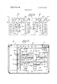
- FIG. 4 is a view taken generally along line 44 of FIG. 5.
- FIG. 5 is a top plan view of the switchgear shown in FIG. I, the view being taken below the slidable top.
- FIG. 6 is a view, similar to FIG. 5, but showing the operators for the loop feeder switches and the grounding switches at one end while the operator for the fuse isolator switch is shown at the other end.
- the reference character 10 designates, generally, metal-enclosed switchgear that is arranged to be mounted on a concrete pad. It includes a metallic housing that is indicated, generally at 11 which may be constructed as disclosed in copending Beebe application Ser. No. 858,458, filed Sept. 16, I969.
- the metallic housing 11 includes metallic side panels 12 and a slidable top 13. On the rear side there are vertically slidably rear panels 14 which, when removed, permit access to cable connections.
- FIG. 2 shows the circuit connections that are employed in the switchgear 10 the details of construction of which are shown in other FIGS. of the drawings.
- load circuit conductors 21a, 21b and 21c are connected to stationary contacts 22a, 22b and 220 that are arranged to receive plug-in contacts 23a, 23b and 230 which are located at one end of fuses 24a, 24b and 240, respectively, which are carried by the insulators 19a, 19b and respectively.
- From the other ends of the fuses contact arms 25a, 25b and 250 extend laterally for engagement with switch blade support plates 26a, 26b and 260 from which fuse isolator switch blades 27a, 27b and 270 extend.
- the switch 28 includes stationary fuse isolator switch contacts 29a, 29b and 290. They are connected respectively to stationary contact conductor plates 30a, 30b and 300.
- the stationary contact conductor plates 30a, 30b and 300 have stationary loop feeder switch contacts 31a, 31b and 31c mounted thereon respectively. These contacts form a part of a three-phase loop feeder switch that is indicated, generally, at
- stationary loop feeder switch contacts 33a, 33b and 330 are also mounted on the stationary contact conductor plates 30a, 30b and 30c, respectively, which form a part of a second three-phase loop feeder switch that is indicated, generally, at 34.
- the loop feeder switches 32 and 34 are arranged, when closed, to connect the respective sides of the loop circuit to the stationary contact conductor plates 30a, 30b and 300 and in turn to the three-phase isolator switch 28. 1
- the loop feeder switch 32 comprises loop feeder switch blades 35a, 35b and 350 which are conjointly movable into and out of contact engagement with the stationary loop feeder switch contacts 31a, 31b and 31c.
- Ground contacts 36a, 36b and 360 of a three-phase ground switch indicated, generally, at 37 are connected, respectively, to the loop feeder switch blades 35a, 35b and 35c.
- the ground switch 37 includes ground switch blades 38a, 38b and 380 arranged for conjoint movement into and out of engagement with the ground contacts 36a, 36b and 360 respectively.
- the grounds for these ground switch blades are indicated at 39a, 39b and 39c.
- the switch blades 35a, 35b and 350 are connected to loop circuit conductors 40a, 40b and 400 respectively.
- the loop feeder switch 34 includes loop feeder switch blades 41a, 41b and 410 which are arranged to engage and disengage, respectively, the stationary loop feeder switch contacts 33a, 33b and 330.
- Ground contacts 42a, 42b and 420 of a three-phase ground switch indicated, generally, at 43 are connected to the switch blades 41a, 41b and 41c, respectively.
- the ground switch 43 includes ground switch blades 44a, 44b and Me and are arranged to engage and disengage the ground contacts 42a, 42b and 420, respectively.
- the grounds for these ground switch blades are indicated at 45a, 45b and 45c.
- the loop feeder switch blades 41a, 41b and Me are connected to loop circuit conductors 46a, 46b and 46c respectively.
- FIG. 3 The connections for several of the systems shown. diagrammatically, in FIG. 2 are illustrated in FIG. 3 by a single line diagram which shows only the connections for one of the phases.
- a typical loop feeder circuit is arranged to be' fed from either or both ends through fuses 51 and 52 or other circuit interrupters.
- Connected in the loop circuit between the fuses 51 and 52 are switch and fuse assemblies that are indicated, generally, at 53 and 54-. It will be understood that a number of these switch and fuse assemblies are connected between the fuses 51 and 52.
- switch and fuse assemblies are indicated, generally, at 53 and 54-. It will be understood that a number of these switch and fuse assemblies are connected between the fuses 51 and 52.
- the same reference characters employed for FIG. 2 are used in FIG. 3 for the corresponding elements.
- loop circuit conductor 40a of the assembly 54 is connected to the fuse 52 while the loop circuit conductor 46a of the assembly 54 is connected to the loop circuit conductor 40a of the assembly 53. Also it will be noted that the loop circuit conductor 46a of assembly 53 is connected to the fuse 51.
- the loop feeder switches 32 and 34 are closed in assembly 54, the loop circuit is continued in series therethrough while the fuse isolator switch 28 is connected to the series connection between these switches. A similar situation is present for assembly 53.
- the system is quite flexible. Assuming that all of the loop feeder switches 32 and 34 are closed, the load circuits 21a are energized through either of the fuses 51 or 52.
- the fuse isolator switch 28 of this assembly is opened.
- the fuse 24a of assembly 53 then can be examined on withdrawal of the respective fusedrawer 17 for inspection or replacement.
- FIG. 3 In FIG. 3 and associated with the assembly 53 there is illustrated an additional fuse 55, it being understood that three fuses and associated equipment are used for a three-phase installation.
- the fuse or fuses 55 are mounted in a drawer, similar to the drawer 17 but located at the opposite end of the housing 11.
- a load circuit 56 is energized through the fuse 55. It is connected thereto through a stationary contact 57 and plugin contact 58 in a manner similar to that previously described.
- a contact arm 59 At the other end of the fuse 55 there is a contact arm 59 for connection to a switch blade support plate 60 that carries a fuse isolator switch blade 61. It forms a part of a fuse isolator switch 62 and is arranged to engage a stationary fuse isolator switch contact 63 which is connected to and mounted on the stationary contact conductor plate 300 in the manner described.
- insulators 66 are provided for individually mounting the stationary contacts 22a, 22b and 22c.
- a terminal rod 67 extends through each of the insulators 66 to provide a connection thereto.
- the insulators 66 are mounted on a panel 68 which forms a part of the metallic housing 11 that acts as a support frame for the mechanism mounted therein.
- insulators 69 mounted on the panel 68, are arranged to support the ground contacts 36a, 36b and 36c of the loop feeder switch 32.
- a terminal rod 70 extends through each of the insulators 69 to permit a cable connection on the rear side of the panel 68.
- insulators 71 mount the ground contacts 42a, 42b and 420 of the loop feeder switch 34. They are carried by the panel 68 and a terminal rod 72 extends through each of them to provide for a connection on the rear side.
- FIGS. 1 and 4 it will be observed that a stack of insulators 73 is provided for mounting therebetween the loop feeder switch blades 35a, 35b and 35c of the loop feeder switch 32.
- the stack of insulators 73 is rotatably mounted at its upper and lower ends on upper and lower channel frame members 74 and 75 which are secured to and extend transversely of upper and lower main frame members 76 and 77. These frame members form a part of the frame structure which includes the metallic housing 11.
- the upper frame member 74 is shown more clearly in FIG. 5 where it will be noted that the stack of insulators 73 is rotatably mounted near one end.
- a stack of insulators 78 is provided for mounting the switch blades 41a, 41b and 410 of the loop feeder switch 34. They are rotatably mounted at their upper and lower ends by the upper and lower channel frame members 74 and 75. As shown in FIG. 5, they are mounted at the opposite ends of these channel members.
- the switch blades of the loop feeder switches 32 and 34 have continuous contact engagement with the ground contacts 36a, 36b and 360 and with the ground contacts 42a, 42b and 42c, respectively, which are connected to the terminal rods 70 and 72.
- shafts 79 and 80 extend upwardly from the stacks of insulators 73 and 78. They are provided for rotating these stacks about vertical axes.
- arms 8l and 82 are connected to the shafts 79 and 80 respectively, and, in turn, the arms 81 and 82 are connected by links 83 and 84 to arms 85 and 86 which are associated with spring operators that are indicated at 87 and 88.
- the spring operators 87 and 88 can be constructed as disclosed in the copending application of Bernatt & Gelfand, Ser. No. 846,694, filed Aug. 1, 1969. However, other operators can be employed if desired.
- Manual operators 89 and 90 are associated with the spring operators 87 and 88 for charging the springs thereof.
- a suitable wrench or tool makes a connection to the manual operators 89 and 90 as will be understood.
- the upper and lower main frame members 76 and 77 are interconnected by front and rear frame members 91 and 92. It will be understood that they are a part of the frame structure including the metallic housing 11.
- a stack of insulators 95 is provided for supporting the fuse isolator'switch blades 27a, 27b and 27c which form a part of the fuse isolator switch 28.
- the stack of insulators 95 is pivotally supported between upper and lower channel frame members 96 and 97 which are interconnected by a vertical frame members 98 and together form a part of the frame structure including the metallic housing 11.
- An arm 99, FIG. 5, extends from the upper endof the stack of insulators 95. It is connected by a link 100 to an arm 10] which forms a part of a spring operator 102 which may be a duplicate of the spring operator 87 and 88.
- a manual operator 103 is arranged to receive a suitable wrench or tool for operas ing the fuse isolator switch 28 between the closed and the open positions.
- the stationary contacts for the fuse isolator switch 28 and the loop feeder. switches 32 and 34 are connected to and mounted on stationary contact conductor plates 30a, 30b and 30c. These contact conductor plates are shown in FIG. 4 where it will be observed that they are stationarily mounted between insulators 106 of a stationary stack of insulators which is mounted between the upper and lower main frame members 76 and 77.
- Arc-extinguishing structures are provided for each phase of the fuse isolator switch 28 operators of the loop feeder switches 32 and 34.
- extinguishing structures are in the form of arc chutes 107, 108 and 109 associated respectively with the switch blades 27a, 27b and 270, the switch blades 35a, 35b and 35c and the switch blades 41a, 41b and 410.
- the construction of the arc chutes 107, 108 and 109 and the respective switches can be as disclosed in .Ieffries copending application, Ser. No. 813,54l, filed Apr. 4, 1969. However, if desired. other switch constructions and arc-extinguishing structures can be used.
- FIGS. 4 and 5 shown metallic ground switch shafts I12 and 113 that are arranged to commonly mount the ground switch blades 38a, 38b and 38c and 44a, 44b and 44:.
- the shafts I12 and 113 are pivotally mounted at their upper and lower ends at the inner ends of the upper and lower main frame members 76 and 77.
- arms 114 and 115 are secured thereto at their upper ends and they are connected by links 116 and 117 to arms 118 and 119 to which manual operators 120 and 121 are connected. Since it is unnecessary to operate the ground switches 37 and 43 witha snap action, the switch operators previously described, are not provided therefor.
- FIG. 6 In order to avoid confusion the arrangement as shown in FIG. 6 can be used. It employs a pad-mounted fuse and switch construction in which the manual operator 103 for the fuse isolator switch 28 alone is located near the front of the metallic housing 11'. At the rear of the metallic housing 11 the manual operators 89 and 90 for the spring operators 87 and 88 are located for controlling the operation of the loop feeder switches32 and 34. Likewise the operators 120 and 121 for the groundswitches 37 and 43 are located at this end of the metallic housing 11. In orderto accommodate the different locations of the, manual operators, links 123 and 124 are employed for interconnecting the anus 81 and 85 and 82 and 86 respectively while a link 125 is employed for interconnecting the arms 99 and 101. Similarly links 126 and 127 are provided for interconnecting the arms 114'and 118 and 115 and 119.
- insulating barriers 128 are shown somewhat diagrammatically in FlGS. 5 and 6 at 128 in various locations to reduce to a minimum the likelihood of flashover to grounded parts. Also interphase insulating barriers 129 and 130, FIG. 4, are suitably mounted between the individual phase-energized parts. An insulating barrier 131 is located in front of the fuse isolator switch 28.
- FIG. 5 it will be noted that the stationary stack of insulators 106 is located at the apex 132. of an isosceles triangle 133 and that the shafts 79 and 80 are located at the ends of the base 134. of the isosceles triangle 133. Also it will be observed that the ground switch shafts 112 and 113 are symmetrically located between the shafts 79 and 80 and on the side of the base 134 of the isosceles triangle 133 away from the apex 132. Thisparticular arrangement provides a compact construction and requires a minimum sizefor themetallic housing 11.
- Loop circuit switching apparatus comprising: a loop electric power supply circuit conductor adapted to be energized from either or both. ends, first and second loop feeder switches connected in series to saidloop circuit conductor, series conductor means connecting, said loop feeder switches in series whereby on closure thereof the loop circuit extends therethrough, a fuse isolator switch connected to said series conductor a means,
- Loop circuit switching apparatus according to claim 1 wherein:
- loop circuit switching apparatus enclose said loop feeder switches and said fuse isolator switch, and a drawer slidably mounted on said housing means has said fuse mounted therein for disconnection from said fuse isolator switch on withdrawal of said drawer.
- each loop feeder switch and said fuseisolator switch includes a stationary contact, and conducting means commonly mount said stationary contacts.
- a second fuse isolator switch is connected to said series conductor means between said loop feeder switches, and
- a second fuse is connected in series with said second fuse isolator switch.
- loop circuit switching apparatus wherein an arc extinguishing structure for each stationary contact is mounted on said conducting means for cooperation with the respective switch blade.
- Loop circuit switching apparatus wherein a grounding switch individual to each feeder switch is arranged when closed to connect the respective feeder switch blade to ground.
- Loop circuit switching apparatus comprising:
- first and second loop feeder switch contacts connected to said contact support plate
- first and second loop feeder switch blades pivoted on said support frame for engaging and disengaging said first and second loop feeder switch contacts respectively
- a fuse isolator switch blade pivoted on said support frame for engaging and disengaging said fuse isolator switch contact
- Loop circuit switching apparatus wherein a drawer mounted on said support frame has said fuse mounted therein for disconnection from said fuse isolator switch blade on withdrawal of said drawer.
- Loop circuit switching apparatus wherein a grounding switch blade individual to each loop feeder switch blade is pivoted on said support frame and is arranged to connect the respective loop feeder switch blade to ground.
- manually operable means is provided on said support frame for each of said operating means.
- loop circuit switching apparatus according to claim 10 wherein said manually operable means all are located at one end of said support frame.
- loop circuit switching apparatus according to claim 10 wherein:
- said manually operable means for said first and second loop feeder switch blades are located at one end of said support frame, and
- said manually operable means for said fuse isolator switch blade is located remotely from said one end of said support frame.
- Loop circuit switching apparatus according to claim 9 wherein:
- manually operable means is provided on said support frame for each of said operating means.
- Loop circuit switching apparatus according to claim 13 wherein said manually operable means all are located at one end of said support frame.
- Loop circuit switching apparatus according to claim 13 wherein:
- said manually operable means for said first and second loop feeder switch blades and for said grounding switch blade are located at one end of said support frame, and
- said manually operable means for said fuse isolator switch blade is located remotely from said one end of support frame.
- loop circuit switching apparatus wherein an arc-extinguishing structure for each switch contact is mounted on said contact support plate for cooperation with the respective switch blade.
- Loop circuit switching apparatus comprising:
- first and second loop feeder switch contacts secured to each contact support plate on opposite sides of said stack of insulators
- first and second loop feeder switch blades fixed between adjacent insulators of said pivoted stacks of insulators respectively for engaging and disengaging the respective loop feeder switch contacts
- a fuse isolator switch blade fixed between adjacent insulators of said third stack of insulators for engaging and disengaging the respective fuse isolator switch contacts
- loop circuit switching apparatus wherein said stationary stack of insulators is located at the apex of an isosceles triangle and said first and second pivoted stacks of insulators are located at the ends of the base of said triangle.
- Loop circuit switching apparatus wherein a drawer mounted on said support frame has said fuses mounted therein for disconnection from said isolator switch blades on withdrawal of said drawer.
- first and second ground switch shafts are pivoted on said support frame, and
- first and second ground switch blades are fixed to said pivoted shafts respectively for grounding the respective first and second loop feeder switch blades.
- Loop circuit switching apparatus according to claim 21 wherein said manually operable means all are located at one end of said support frame.
- said manually operable means for said first and second stacks of insulators are located at one end'of said support frame
- Loop circuit switching apparatus according to claim 24 wherein said manually operable means all are located at one end of said support frame.
- said manually operable means for said first and second stacks of insulators and for said ground switch shafts are located at one end of said sup ort frame, and said manually operable means or said third stack of insulators is located remotely from said one end of said support frame.
- Loop circuit switching apparatus according to claim 17 wherein an arc-extinguishing structure for each switch contact is mounted on the respective contact support plate for cooperation with the respective switch blade.
- said stationary stack of insulators is located at 116 apex of an isosceles triangle
- said first and second pivoted stacks of insulators are located at the ends of the base of said triangle
- ground switch shafts are located between said first and second pivoted stacks of insulators and on the side of said base of said triangle away from said apex.
Abstract
Loop feeder switches have switch blades connected to loop conductors and stationary switch contacts commonly mounted with stationary contacts of fuse isolator switches the blades of which are connected to drawout fuses. Ground switches connect the loop feeder switch blades to ground. Manual operators for the switch blades all are located at one end of the metal enclosed support frame in one embodiment. In another embodiment the manual operator for the fuse isolator switches is remote from the other switch operators. Arc extinguishing structures for the switch contacts cooperate with the respective switch blades.
Description
United States Patent [72] Inventor Joseph Bernatt 3,070,728 12/1962 Edmunds 337/6(X) Arlington Heights, 111. 2,766,351 10/1956 Edsall 337/8 gp;- 33 1969 FOREIGN PATENTS re p Patented p 27,197] 93,700 7/1923 Austria 335/142 [73] Assignee S & C Electric Company Primary Examiner-Bernard A. Gilheany Chicago, 11]. Assistant ExaminerDewitt M. Morgan Attorney-Robert R. Lockwood [54] METAL ENCLOSED LOOP SWITCHES WITH T FUSES FUSE ISOLATOR SWITCHES swiTCHES ABSTRACT: Loop feeder switches have switch blades con- 28 Claims, Drawing Figs. nected to loop conductors and stationary switch contacts commonly mounted with stationary contacts of fuse isolator US. Cl 337/8 Switches the blades f which are connected to drawout f mnHolh Ground switches connect the loop feeder switch blades to [50] Field of Search 307/1 12 groumL Manual operators f the Switch blades n are located y) 113; 55 at one end of the metal enclosed support frame in one embodi- 6 R f C1 ed ment. In another embodiment the manual operator for the [5 1 e erences l fuse isolator switches is remote from the other switch opera- UNITED STATES PATENTS tors. Arc extinguishing structures for the switch contacts 3,088,008 4/1963 Gelzheiser 337/55 (X) cooperate with the respective switch blades.
PATENTED mm m SHEET 2. OF 4 7'0 LOAD 'llllllllllllllllllll VIIIIIIIIIIII PATENTED m2? 197:
SHEET 0F 4 M ETAL ENCLOSED LOOP SWITCHES WIT H DRAWOUT FUSES, FUSE ISOLATOR SWITCHES AND GROUND SWITCHES Metal-enclosed pad-mounted switchgear for distribution of electric power is employed for load circuit protection and sectionalizing loop circuits to isolate faults and to permit servicing. Overall size of the enclosure is important consistent with proper spacing between energized parts and between them and ground. A compact construction efficiently utilizing the space within the metal enclosure is of paramount importance.
Among the objects of this invention are: To isolate drawermounted fuses from a loop circuit without opening the loop circuit; for this purpose to provide -loop feeder switches and fuse isolator switches; to arrange the loop feeder and fuse isolator switches in a pad-mounted metallic enclosure in a compact manner; to provide a common conducting mounting for the stationary contacts of the switches; to provide an arcextinguishing structure for each of the stationary contacts; to provide for grounding the switch blades of the loop feeder switches; to arrange for manually operating the switches at one end of the support structure therefor; and to arrange for manually operating the fuse isolator switches remote from the location where the loop feeder and grounding switches are operated.
According to this invention high-voltage pad-mounted switchgear is provided for loop feeder circuits and fused load circuits. It may be arranged to operate at l kv. or at higher or lower voltages and for single-phase or three-phase circuits. The loop circuits are interconnected by two series-connected loop feeder switches. A third switch or fuse isolator switch connects feeder circuit fuses to the loop. The fuses are mounted in a drawer which can be withdrawn for inspection and replacement. The stationary contacts for the three switches are commonly mounted on a single stationary insulator stack. For each phase there is a stationary conductor plate which carries three stationary contacts, each having an arc extinguishing structure associated therewith and a rotatably mounted switch blade. The switch blades for the two sides of the loop circuit are independently rotatably mounted about vertical axes and thereby selectively permit connection from either side of the loop through the switch blade of the third switch or fuse isolator switch that is rotatably mounted about'a vertical axis and is connected through disconnecting contacts to the respective feeder circuit fuse. Each rotatable switch blade includes a circular contact plate for engagement between a pair of contact fingers for each side of the loop circuit and by a laterally extending contact arm from the feeder circuit fuse.
This switching arrangement provides flexibility in the circuit connections. With the loop feeder switches closed, the feeder circuit fuse can be withdrawn for inspection or replacement after the third switch or fuse isolator switch has been opened. Thus the loop circuit need not be opened. While maintaining I energized the feeder circuit through the fuse or fuses, one or the other of the loop feeder switches can be opened to isolate a fault or to permit servicing of that portion of the loop circuit connected thereto.
If desired, an additional feeder circuit fuse in a second fuse drawer and a second fuse isolator switch can be provided in the metallic housing and arranged and operated in the manner above described for connection to the loop circuit.
In the drawings:
FIG. 1 is a perspective view of metal-enclosed switchgear adapted to be mounted on a concrete pad and embodying this invention, the metal enclosure being shown as if it were transparent in order to permit illustration of the parts enclosed thereby.
FIG. 2 shows diagrammatically the circuit connections employed in the switchgear shown in FIG. 1.
FIG. 3 is a single line diagram illustrating how a number of the switchgear units are connected in a loop circuit.
FIG. 4 is a view taken generally along line 44 of FIG. 5.
FIG. 5 is a top plan view of the switchgear shown in FIG. I, the view being taken below the slidable top.
FIG. 6 is a view, similar to FIG. 5, but showing the operators for the loop feeder switches and the grounding switches at one end while the operator for the fuse isolator switch is shown at the other end.
In FIG. 1 the reference character 10 designates, generally, metal-enclosed switchgear that is arranged to be mounted on a concrete pad. It includes a metallic housing that is indicated, generally at 11 which may be constructed as disclosed in copending Beebe application Ser. No. 858,458, filed Sept. 16, I969. The metallic housing 11 includes metallic side panels 12 and a slidable top 13. On the rear side there are vertically slidably rear panels 14 which, when removed, permit access to cable connections. On the front there are vertically slidable switch access panels 15 and 16 and a fuse drawer that is indicated, generally, at 17. It includes a metallic fuse panel 18 from the rear side of which insulators 19a, 19b and 19c project. As will appear hereinafter, these insulators are arranged to support fuses in the fuse drawer 17.
FIG. 2 shows the circuit connections that are employed in the switchgear 10 the details of construction of which are shown in other FIGS. of the drawings. Here it will be observed that load circuit conductors 21a, 21b and 21c are connected to stationary contacts 22a, 22b and 220 that are arranged to receive plug-in contacts 23a, 23b and 230 which are located at one end of fuses 24a, 24b and 240, respectively, which are carried by the insulators 19a, 19b and respectively. From the other ends of the fuses contact arms 25a, 25b and 250 extend laterally for engagement with switch blade support plates 26a, 26b and 260 from which fuse isolator switch blades 27a, 27b and 270 extend. These switch blades form a part of a threephase fuse isolator switch that is indicated, generally, at 28. The switch 28 includes stationary fuse isolator switch contacts 29a, 29b and 290. They are connected respectively to stationary contact conductor plates 30a, 30b and 300.
The stationary contact conductor plates 30a, 30b and 300 have stationary loop feeder switch contacts 31a, 31b and 31c mounted thereon respectively. These contacts form a part of a three-phase loop feeder switch that is indicated, generally, at
Also mounted on the stationary contact conductor plates 30a, 30b and 30c are stationary loop feeder switch contacts 33a, 33b and 330, respectively, which form a part of a second three-phase loop feeder switch that is indicated, generally, at 34. Now it will be apparent that the loop feeder switches 32 and 34 are arranged, when closed, to connect the respective sides of the loop circuit to the stationary contact conductor plates 30a, 30b and 300 and in turn to the three-phase isolator switch 28. 1
The loop feeder switch 32 comprises loop feeder switch blades 35a, 35b and 350 which are conjointly movable into and out of contact engagement with the stationary loop feeder switch contacts 31a, 31b and 31c. Ground contacts 36a, 36b and 360 of a three-phase ground switch indicated, generally, at 37 are connected, respectively, to the loop feeder switch blades 35a, 35b and 35c. The ground switch 37 includes ground switch blades 38a, 38b and 380 arranged for conjoint movement into and out of engagement with the ground contacts 36a, 36b and 360 respectively. The grounds for these ground switch blades are indicated at 39a, 39b and 39c. The switch blades 35a, 35b and 350 are connected to loop circuit conductors 40a, 40b and 400 respectively.
The loop feeder switch 34 includes loop feeder switch blades 41a, 41b and 410 which are arranged to engage and disengage, respectively, the stationary loop feeder switch contacts 33a, 33b and 330. Ground contacts 42a, 42b and 420 of a three-phase ground switch indicated, generally, at 43 are connected to the switch blades 41a, 41b and 41c, respectively. The ground switch 43 includes ground switch blades 44a, 44b and Me and are arranged to engage and disengage the ground contacts 42a, 42b and 420, respectively. The grounds for these ground switch blades are indicated at 45a, 45b and 45c. The loop feeder switch blades 41a, 41b and Me are connected to loop circuit conductors 46a, 46b and 46c respectively.
The connections for several of the systems shown. diagrammatically, in FIG. 2 are illustrated in FIG. 3 by a single line diagram which shows only the connections for one of the phases. A typical loop feeder circuit is arranged to be' fed from either or both ends through fuses 51 and 52 or other circuit interrupters. Connected in the loop circuit between the fuses 51 and 52 are switch and fuse assemblies that are indicated, generally, at 53 and 54-. It will be understood that a number of these switch and fuse assemblies are connected between the fuses 51 and 52. For illustrative purposes only two of the as semblies are shown. The same reference characters employed for FIG. 2 are used in FIG. 3 for the corresponding elements. It will be noted'that the loop circuit conductor 40a of the assembly 54 is connected to the fuse 52 while the loop circuit conductor 46a of the assembly 54 is connected to the loop circuit conductor 40a of the assembly 53. Also it will be noted that the loop circuit conductor 46a of assembly 53 is connected to the fuse 51. When the loop feeder switches 32 and 34 are closed in assembly 54, the loop circuit is continued in series therethrough while the fuse isolator switch 28 is connected to the series connection between these switches. A similar situation is present for assembly 53. The system is quite flexible. Assuming that all of the loop feeder switches 32 and 34 are closed, the load circuits 21a are energized through either of the fuses 51 or 52. If it is desired to isolate one of the load circuits, for example the load circuit 210 from the assembly 53, the fuse isolator switch 28 of this assembly is opened. The fuse 24a of assembly 53 then can be examined on withdrawal of the respective fusedrawer 17 for inspection or replacement.
, If a fault should occur in the loop circuit between the assemblies 53 and 54, it can be disconnected from the system by opening the loop feeder switch 32 of assembly 53 and the loop feeder switch 34 of assembly 54. The load circuits for these assemblies then will continue to be energized through the fuses 51 and 52 respectively.
' In FIG. 3 and associated with the assembly 53 there is illustrated an additional fuse 55, it being understood that three fuses and associated equipment are used for a three-phase installation. The fuse or fuses 55 are mounted in a drawer, similar to the drawer 17 but located at the opposite end of the housing 11. A load circuit 56 is energized through the fuse 55. It is connected thereto through a stationary contact 57 and plugin contact 58 in a manner similar to that previously described. At the other end of the fuse 55 there is a contact arm 59 for connection to a switch blade support plate 60 that carries a fuse isolator switch blade 61. It forms a part of a fuse isolator switch 62 and is arranged to engage a stationary fuse isolator switch contact 63 which is connected to and mounted on the stationary contact conductor plate 300 in the manner described.
The FIGS. 1 and it will be noted that insulators 66 are provided for individually mounting the stationary contacts 22a, 22b and 22c. A terminal rod 67 extends through each of the insulators 66 to provide a connection thereto. The insulators 66 are mounted on a panel 68 which forms a part of the metallic housing 11 that acts as a support frame for the mechanism mounted therein. In a similar manner insulators 69, mounted on the panel 68, are arranged to support the ground contacts 36a, 36b and 36c of the loop feeder switch 32. A terminal rod 70 extends through each of the insulators 69 to permit a cable connection on the rear side of the panel 68. In a similar manner insulators 71 mount the ground contacts 42a, 42b and 420 of the loop feeder switch 34. They are carried by the panel 68 and a terminal rod 72 extends through each of them to provide for a connection on the rear side.
In FIGS. 1 and 4 it will be observed that a stack of insulators 73 is provided for mounting therebetween the loop feeder switch blades 35a, 35b and 35c of the loop feeder switch 32.
The stack of insulators 73 is rotatably mounted at its upper and lower ends on upper and lower channel frame members 74 and 75 which are secured to and extend transversely of upper and lower main frame members 76 and 77. These frame members form a part of the frame structure which includes the metallic housing 11. The upper frame member 74 is shown more clearly in FIG. 5 where it will be noted that the stack of insulators 73 is rotatably mounted near one end. In a similar manner a stack of insulators 78 is provided for mounting the switch blades 41a, 41b and 410 of the loop feeder switch 34. They are rotatably mounted at their upper and lower ends by the upper and lower channel frame members 74 and 75. As shown in FIG. 5, they are mounted at the opposite ends of these channel members. It will be understood that the switch blades of the loop feeder switches 32 and 34 have continuous contact engagement with the ground contacts 36a, 36b and 360 and with the ground contacts 42a, 42b and 42c, respectively, which are connected to the terminal rods 70 and 72.
As shown in FIG. 5 shafts 79 and 80 extend upwardly from the stacks of insulators 73 and 78. They are provided for rotating these stacks about vertical axes. For pivoting the upstanding shafts 79 and 80 between the switch-closed and the switchopen positions arms 8l and 82 are connected to the shafts 79 and 80 respectively, and, in turn, the arms 81 and 82 are connected by links 83 and 84 to arms 85 and 86 which are associated with spring operators that are indicated at 87 and 88. The spring operators 87 and 88 can be constructed as disclosed in the copending application of Bernatt & Gelfand, Ser. No. 846,694, filed Aug. 1, 1969. However, other operators can be employed if desired. Manual operators 89 and 90 are associated with the spring operators 87 and 88 for charging the springs thereof. A suitable wrench or tool makes a connection to the manual operators 89 and 90 as will be understood. The upper and lower main frame members 76 and 77 are interconnected by front and rear frame members 91 and 92. It will be understood that they are a part of the frame structure including the metallic housing 11.
As shown in FIG. 1 a stack of insulators 95 is provided for supporting the fuse isolator'switch blades 27a, 27b and 27c which form a part of the fuse isolator switch 28. The stack of insulators 95 is pivotally supported between upper and lower channel frame members 96 and 97 which are interconnected by a vertical frame members 98 and together form a part of the frame structure including the metallic housing 11. An arm 99, FIG. 5, extends from the upper endof the stack of insulators 95. It is connected by a link 100 to an arm 10] which forms a part of a spring operator 102 which may be a duplicate of the spring operator 87 and 88. Likewise, a manual operator 103 is arranged to receive a suitable wrench or tool for operas ing the fuse isolator switch 28 between the closed and the open positions.
It will be recalled that the stationary contacts for the fuse isolator switch 28 and the loop feeder. switches 32 and 34 are connected to and mounted on stationary contact conductor plates 30a, 30b and 30c. These contact conductor plates are shown in FIG. 4 where it will be observed that they are stationarily mounted between insulators 106 of a stationary stack of insulators which is mounted between the upper and lower main frame members 76 and 77. By providing this common mounting means for the stationary switch contacts it is possible to provide a very compact construction while still maintaining the necessary electrical clearances between the various energized parts. Arc-extinguishing structures are provided for each phase of the fuse isolator switch 28 operators of the loop feeder switches 32 and 34. These are extinguishing structures are in the form of arc chutes 107, 108 and 109 associated respectively with the switch blades 27a, 27b and 270, the switch blades 35a, 35b and 35c and the switch blades 41a, 41b and 410. The construction of the arc chutes 107, 108 and 109 and the respective switches can be as disclosed in .Ieffries copending application, Ser. No. 813,54l, filed Apr. 4, 1969. However, if desired. other switch constructions and arc-extinguishing structures can be used.
FIGS. 4 and 5 shown metallic ground switch shafts I12 and 113 that are arranged to commonly mount the ground switch blades 38a, 38b and 38c and 44a, 44b and 44:. The shafts I12 and 113 are pivotally mounted at their upper and lower ends at the inner ends of the upper and lower main frame members 76 and 77. For pivoting the ground switch shafts 112 and 113 arms 114 and 115 are secured thereto at their upper ends and they are connected by links 116 and 117 to arms 118 and 119 to which manual operators 120 and 121 are connected. Since it is unnecessary to operate the ground switches 37 and 43 witha snap action, the switch operators previously described, are not provided therefor.
ln P16. 5 it will be observed that provision is made for operating the fuse isolator switch 28, the loop feeder switches 32 and 3,4, and the ground switches 37 and 43 all from near the front of the metallic housing 11. This is permitted when the top 13 is slid rearwardly to permit access to the various manual operators.
in order to avoid confusion the arrangement as shown in FIG. 6 can be used. It employs a pad-mounted fuse and switch construction in which the manual operator 103 for the fuse isolator switch 28 alone is located near the front of the metallic housing 11'. At the rear of the metallic housing 11 the manual operators 89 and 90 for the spring operators 87 and 88 are located for controlling the operation of the loop feeder switches32 and 34. Likewise the operators 120 and 121 for the groundswitches 37 and 43 are located at this end of the metallic housing 11. In orderto accommodate the different locations of the, manual operators, links 123 and 124 are employed for interconnecting the anus 81 and 85 and 82 and 86 respectively while a link 125 is employed for interconnecting the arms 99 and 101. Similarly links 126 and 127 are provided for interconnecting the arms 114'and 118 and 115 and 119.
Various insulating barriers 128 are shown somewhat diagrammatically in FlGS. 5 and 6 at 128 in various locations to reduce to a minimum the likelihood of flashover to grounded parts. Also interphase insulating barriers 129 and 130, FIG. 4, are suitably mounted between the individual phase-energized parts. An insulating barrier 131 is located in front of the fuse isolator switch 28.
ln FIG. 5 it will be noted that the stationary stack of insulators 106 is located at the apex 132. of an isosceles triangle 133 and that the shafts 79 and 80 are located at the ends of the base 134. of the isosceles triangle 133. Also it will be observed that the ground switch shafts 112 and 113 are symmetrically located between the shafts 79 and 80 and on the side of the base 134 of the isosceles triangle 133 away from the apex 132. Thisparticular arrangement provides a compact construction and requires a minimum sizefor themetallic housing 11.
lclaim; 1. Loop circuit switching apparatus comprising: a loop electric power supply circuit conductor adapted to be energized from either or both. ends, first and second loop feeder switches connected in series to saidloop circuit conductor, series conductor means connecting, said loop feeder switches in series whereby on closure thereof the loop circuit extends therethrough, a fuse isolator switch connected to said series conductor a means,
a load circuit, and a fuse connected in series with said fuse isolator switch and to said load circuit whereby saidload circuit is connected to said loop circuit conductor when-either or both of said loop feeder switches is closed. 2. Loop circuit switching apparatus according to claim 1 wherein:
housing means enclose said loop feeder switches and said fuse isolator switch, and a drawer slidably mounted on said housing means has said fuse mounted therein for disconnection from said fuse isolator switch on withdrawal of said drawer. 3. Loop circuit switching apparatus according to claim 1 wherein:
each loop feeder switch and said fuseisolator switch includesa stationary contact, and conducting means commonly mount said stationary contacts.
4. Loop circuit switching apparatus according to claim 1 wherein:
a second fuse isolator switch is connected to said series conductor means between said loop feeder switches, and
a second fuse is connected in series with said second fuse isolator switch.
5. Loop circuit switching apparatus according to claim 3 wherein an arc extinguishing structure for each stationary contact is mounted on said conducting means for cooperation with the respective switch blade.
6. Loop circuit switching apparatus according to claim 3 wherein a grounding switch individual to each feeder switch is arranged when closed to connect the respective feeder switch blade to ground.
7. Loop circuit switching apparatus comprising:
a support frame,
a stationary insulator on said support frame,
a contact support plate on said stationary insulator,
first and second loop feeder switch contacts connected to said contact support plate,
first and second loop feeder switch blades pivoted on said support frame for engaging and disengaging said first and second loop feeder switch contacts respectively,
a fuse isolator switch contact connected to said contact support plate,
a fuse isolator switch blade pivoted on said support frame for engaging and disengaging said fuse isolator switch contact, and
a fuse on said support frame connected to said fuse isolator switch blade.
8. Loop circuit switching apparatus according to claim 7 wherein a drawer mounted on said support frame has said fuse mounted therein for disconnection from said fuse isolator switch blade on withdrawal of said drawer.
9. Loop circuit switching apparatus according to claim 7 wherein a grounding switch blade individual to each loop feeder switch blade is pivoted on said support frame and is arranged to connect the respective loop feeder switch blade to ground.
. l0. Loop circuit switching apparatus according to claim 7 wherein:
operating means individual to each switch blade is arranged to pivot it between open and closed positions, and
manually operable means is provided on said support frame for each of said operating means.
11. Loop circuit switching apparatus according to claim 10 wherein said manually operable means all are located at one end of said support frame.
12. Loop circuit switching apparatus according to claim 10 wherein:
said manually operable means for said first and second loop feeder switch blades are located at one end of said support frame, and
said manually operable means for said fuse isolator switch blade is located remotely from said one end of said support frame.
13. Loop circuit switching apparatus according to claim 9 wherein:
operating means individual to each switch blade is arranged to pivot it between open and closed positions, and
manually operable means is provided on said support frame for each of said operating means.
14. Loop circuit switching apparatus according to claim 13 wherein said manually operable means all are located at one end of said support frame.
15. Loop circuit switching apparatus according to claim 13 wherein:
said manually operable means for said first and second loop feeder switch blades and for said grounding switch blade are located at one end of said support frame, and
said manually operable means for said fuse isolator switch blade is located remotely from said one end of support frame.
16. Loop circuit switching apparatus according to claim 7 wherein an arc-extinguishing structure for each switch contact is mounted on said contact support plate for cooperation with the respective switch blade.
17. Loop circuit switching apparatus comprising:
a support frame,
a stationary stack of insulators on said support frame,
a contact support plate between adjacent insulators of said stack,
first and second loop feeder switch contacts secured to each contact support plate on opposite sides of said stack of insulators,
first and second stacks of insulators pivoted on said support frame,
first and second loop feeder switch blades fixed between adjacent insulators of said pivoted stacks of insulators respectively for engaging and disengaging the respective loop feeder switch contacts,
a fuse isolator switch contact on each contact support plate,
a third stack of insulators pivoted on said support frame,
a fuse isolator switch blade fixed between adjacent insulators of said third stack of insulators for engaging and disengaging the respective fuse isolator switch contacts, and
a fuse on said support frame connected to each fuse isolator switch blade.
18. Loop circuit switching apparatus according to claim 17 wherein said stationary stack of insulators is located at the apex of an isosceles triangle and said first and second pivoted stacks of insulators are located at the ends of the base of said triangle.
19. Loop circuit switching apparatus according to claim 17 wherein a drawer mounted on said support frame has said fuses mounted therein for disconnection from said isolator switch blades on withdrawal of said drawer.
20. Loop circuit switching apparatus according to claim 17 wherein:
first and second ground switch shafts are pivoted on said support frame, and
first and second ground switch blades are fixed to said pivoted shafts respectively for grounding the respective first and second loop feeder switch blades.
21. Loop circuit switching apparatus according to claim 17 wherein:
operating means individual to each of said stacks of insulators for pivoting them between open and closed positions,
ii. and manually operable means on said support frame for each operating means.
22. Loop circuit switching apparatus according to claim 21 wherein said manually operable means all are located at one end of said support frame.
23. Loop circuit switching apparatus according to claim 21 wherein:
said manually operable means for said first and second stacks of insulators are located at one end'of said support frame, and
said manually operable means for said third stack of insulators is located remotely from said one end of said support frame. 24. Loop circuit switching apparatus according to claim 21 wherein:
operating means individual to each of said stacks of insulators and to each of said ground switch shafts for pivoting them between their respective operating positions, and
manually operable means on said support frame for each of said operating means.
25. Loop circuit switching apparatus according to claim 24 wherein said manually operable means all are located at one end of said support frame.
26. Loop circuit switching apparatus according to claim 24 wherein:
said manually operable means for said first and second stacks of insulators and for said ground switch shafts are located at one end of said sup ort frame, and said manually operable means or said third stack of insulators is located remotely from said one end of said support frame.
27. Loop circuit switching apparatus according to claim 17 wherein an arc-extinguishing structure for each switch contact is mounted on the respective contact support plate for cooperation with the respective switch blade.
28. Loop circuit switching apparatus according to claim 20 wherein:
said stationary stack of insulators is located at 116 apex of an isosceles triangle,
said first and second pivoted stacks of insulators are located at the ends of the base of said triangle, and
said ground switch shafts are located between said first and second pivoted stacks of insulators and on the side of said base of said triangle away from said apex.
Claims (28)
1. Loop circuit switching apparatus comprising: a loop electric power supply circuit conductor adapted to be energized from either or both ends, first and second loop feeder switches connected in series to said loop circuit conductor, series conductor means connecting said loop feeder switches in series whereby on closure thereof the loop circuit extends therethrough, a fuse isolator switch connected to said series conductor means, a load circuit, and a fuse connected in series with said fuse isolator switch and to said load circuit whereby said load circuit is connected to said loop circuit conductor when either or both of said loop feeder switches is closed.
2. Loop circuit switching apparatus according to claim 1 wherein: housing means enclose said loop feeder switches and said fuse isolator switch, and a drawer slidably mounted on said housing means has said fuse mounted therein for disconnection from said fuse isolator switch on withdrawal of said drawer.
3. Loop circuit switching apparatus according to claim 1 wherein: each loop feeder switch and said fuse isolator switch includes a stationary contact, and conducting means commonly mount said stationary contacts.
4. Loop circuit switching apparatus according to claim 1 wherein: a second fuse isolator switch is connected to said series conductor means between said loop feeder switches, and a second fuse is connected in series with said second fuse isolator switch.
5. Loop circuit switching apparatus according to claim 3 wherein an arc extinguishing structure for each stationary contact is mounted on said conducting means for cooperation with the respective switch blade.
6. Loop circuit switching apparatus according to claim 3 wherein a grounding switch individual to each feeder switch is arranged when closed to connect the respective feeder switch blade to ground.
7. Loop circuit switching apparatus comprising: a support frame, a stationary insulator on said support frame, a contact support plate on said stationary insulator, first and second loop feeder switch contacts connected to said contact support plate, fiRst and second loop feeder switch blades pivoted on said support frame for engaging and disengaging said first and second loop feeder switch contacts respectively, a fuse isolator switch contact connected to said contact support plate, a fuse isolator switch blade pivoted on said support frame for engaging and disengaging said fuse isolator switch contact, and a fuse on said support frame connected to said fuse isolator switch blade.
8. Loop circuit switching apparatus according to claim 7 wherein a drawer mounted on said support frame has said fuse mounted therein for disconnection from said fuse isolator switch blade on withdrawal of said drawer.
9. Loop circuit switching apparatus according to claim 7 wherein a grounding switch blade individual to each loop feeder switch blade is pivoted on said support frame and is arranged to connect the respective loop feeder switch blade to ground.
10. Loop circuit switching apparatus according to claim 7 wherein: operating means individual to each switch blade is arranged to pivot it between open and closed positions, and manually operable means is provided on said support frame for each of said operating means.
11. Loop circuit switching apparatus according to claim 10 wherein said manually operable means all are located at one end of said support frame.
12. Loop circuit switching apparatus according to claim 10 wherein: said manually operable means for said first and second loop feeder switch blades are located at one end of said support frame, and said manually operable means for said fuse isolator switch blade is located remotely from said one end of said support frame.
13. Loop circuit switching apparatus according to claim 9 wherein: operating means individual to each switch blade is arranged to pivot it between open and closed positions, and manually operable means is provided on said support frame for each of said operating means.
14. Loop circuit switching apparatus according to claim 13 wherein said manually operable means all are located at one end of said support frame.
15. Loop circuit switching apparatus according to claim 13 wherein: said manually operable means for said first and second loop feeder switch blades and for said grounding switch blade are located at one end of said support frame, and said manually operable means for said fuse isolator switch blade is located remotely from said one end of support frame.
16. Loop circuit switching apparatus according to claim 7 wherein an arc-extinguishing structure for each switch contact is mounted on said contact support plate for cooperation with the respective switch blade.
17. Loop circuit switching apparatus comprising: a support frame, a stationary stack of insulators on said support frame, a contact support plate between adjacent insulators of said stack, first and second loop feeder switch contacts secured to each contact support plate on opposite sides of said stack of insulators, first and second stacks of insulators pivoted on said support frame, first and second loop feeder switch blades fixed between adjacent insulators of said pivoted stacks of insulators respectively for engaging and disengaging the respective loop feeder switch contacts, a fuse isolator switch contact on each contact support plate, a third stack of insulators pivoted on said support frame, a fuse isolator switch blade fixed between adjacent insulators of said third stack of insulators for engaging and disengaging the respective fuse isolator switch contacts, and a fuse on said support frame connected to each fuse isolator switch blade.
18. Loop circuit switching apparatus according to claim 17 wherein said stationary stack of insulators is located at the apex of an isosceles triangle and said first and second pivoted stacks of insulators are located at the ends of the base of said triangle.
19. Loop circuit switching apparatus according to claiM 17 wherein a drawer mounted on said support frame has said fuses mounted therein for disconnection from said isolator switch blades on withdrawal of said drawer.
20. Loop circuit switching apparatus according to claim 17 wherein: first and second ground switch shafts are pivoted on said support frame, and first and second ground switch blades are fixed to said pivoted shafts respectively for grounding the respective first and second loop feeder switch blades.
21. Loop circuit switching apparatus according to claim 17 wherein: operating means individual to each of said stacks of insulators for pivoting them between open and closed positions, and manually operable means on said support frame for each operating means.
22. Loop circuit switching apparatus according to claim 21 wherein said manually operable means all are located at one end of said support frame.
23. Loop circuit switching apparatus according to claim 21 wherein: said manually operable means for said first and second stacks of insulators are located at one end of said support frame, and said manually operable means for said third stack of insulators is located remotely from said one end of said support frame.
24. Loop circuit switching apparatus according to claim 21 wherein: operating means individual to each of said stacks of insulators and to each of said ground switch shafts for pivoting them between their respective operating positions, and manually operable means on said support frame for each of said operating means.
25. Loop circuit switching apparatus according to claim 24 wherein said manually operable means all are located at one end of said support frame.
26. Loop circuit switching apparatus according to claim 24 wherein: said manually operable means for said first and second stacks of insulators and for said ground switch shafts are located at one end of said support frame, and said manually operable means for said third stack of insulators is located remotely from said one end of said support frame.
27. Loop circuit switching apparatus according to claim 17 wherein an arc-extinguishing structure for each switch contact is mounted on the respective contact support plate for cooperation with the respective switch blade.
28. Loop circuit switching apparatus according to claim 20 wherein: said stationary stack of insulators is located at 116 apex of an isosceles triangle, said first and second pivoted stacks of insulators are located at the ends of the base of said triangle, and said ground switch shafts are located between said first and second pivoted stacks of insulators and on the side of said base of said triangle away from said apex.
Applications Claiming Priority (1)
| Application Number | Priority Date | Filing Date | Title |
|---|---|---|---|
| US85997669A | 1969-09-22 | 1969-09-22 |
Publications (1)
| Publication Number | Publication Date |
|---|---|
| US3576509A true US3576509A (en) | 1971-04-27 |
Family
ID=25332208
Family Applications (1)
| Application Number | Title | Priority Date | Filing Date |
|---|---|---|---|
| US859976A Expired - Lifetime US3576509A (en) | 1969-09-22 | 1969-09-22 | Metal enclosed loop switches with drawout fuses, fuse isolator switches and ground switches |
Country Status (2)
| Country | Link |
|---|---|
| US (1) | US3576509A (en) |
| GB (1) | GB1326220A (en) |
Cited By (8)
| Publication number | Priority date | Publication date | Assignee | Title |
|---|---|---|---|---|
| US3790861A (en) * | 1972-10-10 | 1974-02-05 | S & C Electric Co | Switchgear with fuses individually mounted on fuse carriers and switches therefor for interlocks |
| US3909762A (en) * | 1974-10-31 | 1975-09-30 | Kuhlman Corp | Circuit breaker and fuse interlock mechanism |
| US3952273A (en) * | 1975-04-01 | 1976-04-20 | S & C Electric Company | High voltage switch mechanism |
| US3951015A (en) * | 1975-04-01 | 1976-04-20 | S & C Electric Company | Fuse handling tool |
| US4777559A (en) * | 1984-10-24 | 1988-10-11 | S&C Electric Company | Article mounting and handling method and apparatus |
| US5590018A (en) * | 1994-07-25 | 1996-12-31 | Hitachi, Ltd. | Arrangement of arrestors in a gas-insulated switchgear |
| US5982267A (en) * | 1999-01-28 | 1999-11-09 | General Electric Company | Fuse holder for distribution transformers |
| US20090066471A1 (en) * | 2005-04-18 | 2009-03-12 | Abb Technology Ag | Fuse arrangement |
Citations (4)
| Publication number | Priority date | Publication date | Assignee | Title |
|---|---|---|---|---|
| AT93700B (en) * | 1918-01-12 | 1923-07-25 | Richard Dreyer | Protection device for electrical circuits. |
| US2766351A (en) * | 1955-01-28 | 1956-10-09 | Chase Shawmut Co | Enclosed switch and fuse units |
| US3070728A (en) * | 1957-08-16 | 1962-12-25 | Ite Circuit Breaker Ltd | Selective trip arrangement utilizing circuit breakers which are coordinated with current limiting fuses |
| US3088008A (en) * | 1959-11-03 | 1963-04-30 | Westinghouse Electric Corp | Circuit breaker |
-
1969
- 1969-09-22 US US859976A patent/US3576509A/en not_active Expired - Lifetime
-
1970
- 1970-09-08 GB GB4292970A patent/GB1326220A/en not_active Expired
Patent Citations (4)
| Publication number | Priority date | Publication date | Assignee | Title |
|---|---|---|---|---|
| AT93700B (en) * | 1918-01-12 | 1923-07-25 | Richard Dreyer | Protection device for electrical circuits. |
| US2766351A (en) * | 1955-01-28 | 1956-10-09 | Chase Shawmut Co | Enclosed switch and fuse units |
| US3070728A (en) * | 1957-08-16 | 1962-12-25 | Ite Circuit Breaker Ltd | Selective trip arrangement utilizing circuit breakers which are coordinated with current limiting fuses |
| US3088008A (en) * | 1959-11-03 | 1963-04-30 | Westinghouse Electric Corp | Circuit breaker |
Cited By (9)
| Publication number | Priority date | Publication date | Assignee | Title |
|---|---|---|---|---|
| US3790861A (en) * | 1972-10-10 | 1974-02-05 | S & C Electric Co | Switchgear with fuses individually mounted on fuse carriers and switches therefor for interlocks |
| US3909762A (en) * | 1974-10-31 | 1975-09-30 | Kuhlman Corp | Circuit breaker and fuse interlock mechanism |
| US3952273A (en) * | 1975-04-01 | 1976-04-20 | S & C Electric Company | High voltage switch mechanism |
| US3951015A (en) * | 1975-04-01 | 1976-04-20 | S & C Electric Company | Fuse handling tool |
| US4777559A (en) * | 1984-10-24 | 1988-10-11 | S&C Electric Company | Article mounting and handling method and apparatus |
| US5590018A (en) * | 1994-07-25 | 1996-12-31 | Hitachi, Ltd. | Arrangement of arrestors in a gas-insulated switchgear |
| US5982267A (en) * | 1999-01-28 | 1999-11-09 | General Electric Company | Fuse holder for distribution transformers |
| US20090066471A1 (en) * | 2005-04-18 | 2009-03-12 | Abb Technology Ag | Fuse arrangement |
| US8018317B2 (en) * | 2005-04-18 | 2011-09-13 | Abb Technology Ag | Fuse arrangement |
Also Published As
| Publication number | Publication date |
|---|---|
| GB1326220A (en) | 1973-08-08 |
Similar Documents
| Publication | Publication Date | Title |
|---|---|---|
| RU2195734C2 (en) | Vacuum switch and vacuum switchgear | |
| US3339118A (en) | Metal enclosed switchgear with one or more fuses mounted on a drawer interlocked with interrupter switch means and operating mechanism therefor | |
| EP0471678B1 (en) | Load switching device with a three-position switch | |
| KR100319407B1 (en) | Arc quenching device for ring main unit | |
| US9595412B2 (en) | Control panel including solid-insulated plug-in connection | |
| US10923888B2 (en) | Interchangeable switchgear modules and related systems | |
| US7075778B2 (en) | Hybrid gas-insulated switchgear | |
| US4745522A (en) | Gas-insulated switchgear apparatus | |
| US3576509A (en) | Metal enclosed loop switches with drawout fuses, fuse isolator switches and ground switches | |
| US4215256A (en) | Gas-insulated switchgear apparatus | |
| CN104979129B (en) | The medium-voltage switchgear switched including every phase two | |
| JP3175434B2 (en) | Gas insulated switchgear | |
| WO2011145749A1 (en) | Cubicle-type gas-insulated switching apparatus | |
| SE440573B (en) | CAPSLAT STELLVERK | |
| US3397293A (en) | Metal-clad switchgear employing vacuum type circuit interrupters | |
| US3603752A (en) | Grounding-switch device | |
| DE3820489A1 (en) | Encapsulated switch disconnector arrangement | |
| US3842381A (en) | Integral fuse and switch support for metal-enclosed switch gear | |
| US2914627A (en) | Draw-out type switch-fuse assembly | |
| RU2217851C1 (en) | Switchgear and control gear | |
| US3842321A (en) | Electrical switchgear with primary and secondary switch means associated with current transformer | |
| PL187349B1 (en) | Gas-insulated switchgear employing sf 6 gas for power distribution networks | |
| JPH02210389A (en) | Cell for medium or high pressure metal clad station and station built with cell of this type | |
| US3194928A (en) | Center break high voltage switch with circuit interrupters | |
| RU2287200C1 (en) | High-voltage load circuit breaker |