US3614259A - Turbine casing - Google Patents
Turbine casing Download PDFInfo
- Publication number
- US3614259A US3614259A US855270A US3614259DA US3614259A US 3614259 A US3614259 A US 3614259A US 855270 A US855270 A US 855270A US 3614259D A US3614259D A US 3614259DA US 3614259 A US3614259 A US 3614259A
- Authority
- US
- United States
- Prior art keywords
- turbine
- casing
- parts
- partition
- gas
- Prior art date
- Legal status (The legal status is an assumption and is not a legal conclusion. Google has not performed a legal analysis and makes no representation as to the accuracy of the status listed.)
- Expired - Lifetime
Links
Images

Classifications
-
- F—MECHANICAL ENGINEERING; LIGHTING; HEATING; WEAPONS; BLASTING
- F01—MACHINES OR ENGINES IN GENERAL; ENGINE PLANTS IN GENERAL; STEAM ENGINES
- F01D—NON-POSITIVE DISPLACEMENT MACHINES OR ENGINES, e.g. STEAM TURBINES
- F01D17/00—Regulating or controlling by varying flow
- F01D17/10—Final actuators
- F01D17/12—Final actuators arranged in stator parts
- F01D17/14—Final actuators arranged in stator parts varying effective cross-sectional area of nozzles or guide conduits
- F01D17/146—Final actuators arranged in stator parts varying effective cross-sectional area of nozzles or guide conduits by throttling the volute inlet of radial machines or engines
-
- F—MECHANICAL ENGINEERING; LIGHTING; HEATING; WEAPONS; BLASTING
- F01—MACHINES OR ENGINES IN GENERAL; ENGINE PLANTS IN GENERAL; STEAM ENGINES
- F01D—NON-POSITIVE DISPLACEMENT MACHINES OR ENGINES, e.g. STEAM TURBINES
- F01D9/00—Stators
- F01D9/02—Nozzles; Nozzle boxes; Stator blades; Guide conduits, e.g. individual nozzles
- F01D9/026—Scrolls for radial machines or engines
-
- F—MECHANICAL ENGINEERING; LIGHTING; HEATING; WEAPONS; BLASTING
- F02—COMBUSTION ENGINES; HOT-GAS OR COMBUSTION-PRODUCT ENGINE PLANTS
- F02B—INTERNAL-COMBUSTION PISTON ENGINES; COMBUSTION ENGINES IN GENERAL
- F02B37/00—Engines characterised by provision of pumps driven at least for part of the time by exhaust
- F02B37/02—Gas passages between engine outlet and pump drive, e.g. reservoirs
- F02B37/025—Multiple scrolls or multiple gas passages guiding the gas to the pump drive
-
- Y—GENERAL TAGGING OF NEW TECHNOLOGICAL DEVELOPMENTS; GENERAL TAGGING OF CROSS-SECTIONAL TECHNOLOGIES SPANNING OVER SEVERAL SECTIONS OF THE IPC; TECHNICAL SUBJECTS COVERED BY FORMER USPC CROSS-REFERENCE ART COLLECTIONS [XRACs] AND DIGESTS
- Y02—TECHNOLOGIES OR APPLICATIONS FOR MITIGATION OR ADAPTATION AGAINST CLIMATE CHANGE
- Y02T—CLIMATE CHANGE MITIGATION TECHNOLOGIES RELATED TO TRANSPORTATION
- Y02T10/00—Road transport of goods or passengers
- Y02T10/10—Internal combustion engine [ICE] based vehicles
- Y02T10/12—Improving ICE efficiencies
Definitions
- a valve When used as a variable speed turbine, a valve is [56] References cued provided in the inlet portion of the casing to direct gas sup- UNITED STATES PATENTS plied to the inlet portion into one or the other or both parts of 3,557,549 1/ 1971 Webster 415/205 the divided inlet to provide difierent ranges of gas velocity at 3,178,882 4/ 1965 Milligan 60/13 the turbine wheel and consequently different ranges of turbine 3,218,029 11/1965 Wo011enweber,.lr 415/205 speed.
- turbochargers Due to the increased power and other advantages obtained from internal combustion engines utilizing exhaust gas driven turbochargers, greater use is being made of turbochargers than ever before. In recent years, the turbine casing of such turbochargers has undergone considerable development in order to more effectively utilize the energy in the exhaust gas and thereby increase the overall efficiency of the turbocharger and engine.
- Such turbines have a casing designed to transmit the kinetic energy of the pulses in the exhaust gas flow from the engine, upon opening of the exhaust valves, to the turbine wheelwith minimum energy loss.
- the casings of most of the pulse turbines presently in use have a partition dividing the casing into two parts so that the pulsating flow of exhaust gas from certain of the cylinders of the engine is directed into one part of the casing and the pulsating flow of exhaust gas from the other cylinders is directed into the other part of the casing.
- the flow of exhaust gas from the cylinders of one bank would be supplied to one part of the divided turbine casing and the flow of exhaust gas from the cylinders of the other bank would be supplied to the other part of the casing.
- variable speed turbine Another type of turbine heretofore utilized in turbochargers adapted for use with internal combustion engines, is the variable speed turbine. While variable speed turbines are generally old and well known, a variable speed turbine employing a divided turbine casing in connection with a valve to direct the flow of exhaust gas from the engine into one or both parts of the casing in order to vary the velocity of the flow of exhaust gas to the turbine wheel and hence the speed of the turbine, is a comparatively recent development.
- variable speed turbine which employs a divided turbine casing, has not proved satisfactory for its intended purpose, for various reasons.
- One of the reasons for such unsatisfactory performance is loss of efficiency due to a partially filled turbine wheel entrance or throat, which results in expansion losses in the inducer blade area of the turbine wheel.
- Another object is to provide a novel divided turbine casing for a gas turbine adapted to be driven by a pulsating exhaust gas flow from an internal combustion engine, wherein the easing transmits the pulses in the exhaust gas flow to the associated turbine wheel with minimum energy loss.
- Still another object is to provide a novel divided turbine casing adapted to be driven by pulsating exhaust gas flows from different groups of cylinders of a multicylinder internal combustion engine, wherein the pulses from one group of cylinders are prevented from adversely afiecting the flow from another group of cylinders.
- a further object is to provide a novel divided turbine casing and valve means for a gas turbine, wherein the valve means is effective to cause operation of the turbine at three different ranges of speed.
- a still further object is to provide a novel turbine casing and valve means for the turbine of an exhaust gas driven turbocharger, wherein the turbine casing is divided into two parts of different size by a partition and wherein the valve means directs exhaust gas into one or the other or both parts of the casing to control the ranges of speed of the turbine.
- FIG. 1 is an elevational view axially of a turbine casing embodying the invention
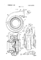
- FIG. 2 is a sectional view taken along the line 2-2 of FIG. l, and showing the relationship of the casing to an associated turbine wheel;
- FIG. 3 is an elevational view of the right side of the turbine casing as viewed in FIG. 1;
- FIG. 4 is an elevational view of another turbine casing embodying the invention and similar to FIG. 1, but with a portion thereof broken away to show internal details;
- FIG. 5 is a sectional view taken substantially along the line 5-5 of FIG. 4.
- the present invention contemplates a novel turbine casing adapted to convey a flow of gas to an associated turbine wheel.
- the turbine casing includes a volute portion adapted to surround the turbine wheel, an inlet portion connected to and extending generally tangentially toward the volute, and an annular throat adapted to direct the gas flow from the volute por tion into the spaces between the blades of the turbine wheel for driving the latter.
- a partition is provided in the interior of the casing for dividing the volute portion into two parts of different radii from the axis of the casing to the centers of the cross-sectional areas of the respective parts, the partition being conical with respect to the axis of the turbine casing in the volute portion.
- the radially inner edge of the partition is positioned substantially at the outer periphery of the throat and is beveled on at least one side to prevent separation of the flow from the walls of the throat.
- the partition twists from a perpendicular position with respect to the axis of the casing to the conical form in the volute portion.
- the turbine casing is adapted to utilize the pulses in gas flows from two different groups of cylinders of an associated internal combustion engine, the turbine thus functioning as a pulse turbine.
- the two parts of the divided turbine casing are adapted to receive separate flows of pulsating exhaust gas from the respective groups of cylinders of the engine, and to transmit the pulses in the flows to an associated turbine wheel without any significant loss of energy and without any adverse affects on the respective flows.
- Such operation is obtained by connecting one of the divided inlet portions to one group of cylinders of the engine, and the other divided inlet portion to the other group of cylinders of the engine.
- the groups of cylinders are chosen so that the pulses in the flow from the one group do not enter the throat of the casing at the same time that the pulses in the flow from the other group enter the throat.
- the turbine casing is adapted to provide a variable speed turbine.
- valve means of the flapper type and fonning a continuation of the partition is provided in the inlet portion for directing the flow of exhaust gas from the cylinders of the engine into one or the other or both parts of the casing, depending upon the position of the valve.
- the valve means is arranged to be swung from one side to the other of the inlet portion of the casing and thus prevent flow through one or the other of the two parts of the casing, or to be centered in the inlet portion and thus permit flow through both parts of the casing.
- the twoparts of the volute portion of the turbine casing have different AIR ratios, where A is the cross-sectional area of the respective parts at the start of the volute portion and R" is the radius from the axis of the casing to the center of that cross-sectional area.
- Two different AIR ratios may, of course, be obtained by varying A or R or both.
- use of the respective parts will provide two different ranges of gas velocity at the periphery of the turbine wheel.
- another A/R ratio will be obtained, which is different from that obtained by use of either part alone. Consequently, another range of gas velocity may be obtained at the turbine wheel periphery.
- movement of the valve means to its various positions in the inlet portion of the casing will provide three different ranges of gas velocity I at the periphery of the turbine wheel, and consequently three different ranges of turbine speed.
- a turbine casing embodying the invention is adapted to be connected to a source of gas under pressure.
- a turbine casing is illustrated, which is adapted to be connected to a pulsating source of gas under pressure such as the exhaust flow from an internal combustion engine having poppet-type exhaust valves.
- the turbine casing illustrated in these figures is divided into two parts which receive pulses from different groups of cylinders of the engine.
- Such casing comprises a volute portion 11, an inlet portion 12 which extends generally tangentially with respect to the volute portion 1 1, an annularthroat 13 at the radially inner periphery of the volute portion, and an annular outlet portion 14 which extends axially outwardly from one side of the volute portion 1 1.
- the outlet portion 14 extends from the left side of the volute portion, as viewed in FIG. 2.
- the opposite or right side of the casing, as viewed in FIG. 2 includes an annular, axially extending mounting portion 16 having a radially outwardly extending flange 17 around the outer end thereof.
- the mounting portion 16 is adapted to telescope over one end 22 of a cylindrical member such as a bearing support housing 23 fragmentarily shown in FIGS. 2 and 3.
- a bearing 24, also fragmentarily shown in FIG. 2 is mounted in the housing 23, and a shaft 26 is rotatably journaled in the bearing 24.
- a turbine wheel 30 having a plurality of radially extending, circumferentially spaced blades 31, is shown mounted on the left end of the shaft 26 for driving the latter.
- gas from the throat 13 of the turbine casing will flow radially inwardly into the spaces between the blades 31 at the radially outer ends 32 thereof, and then gradually changes direction from substantially radial to substantially axial before discharging through the outlet portion 14 of the casing.
- turbine casing is to be used to provide the turbine portion of an exhaust gas driven turbocharger, a compressor wheel (not shown) is secured to the opposite end of the shaft 26 and a compressor casing (also not shown) is mounted on the opposite end of the bearing support housing 23.
- the support housing 23, shaft 26, turbine wheel 30, compressor and compressor casing form no part of the present invention, and therefore no further description thereof will be included.
- the turbine casing illustrated in FIGS. 1, 2 and 3 is effective to transmit pulsations in two separate streams of gas flowing to the casing and to transmit the pulses in the streams to the turbine wheel 31 without any significant loss of energy and without any adverse affects between the respective streams such as the pulses in one stream tending to oppose the other stream.
- the turbine casing illustrated in FIGS. 1, 2 and 3 is effective, when used in conjunction with an appropriate turbine wheel, to provide a highly efficient pulse turbine.
- An example of one source of pulsating gas to which the turbine casing illustrated in FIGS. 1, 2 and 3 is particularly adapted is the exhaust system of an internal combustion engine utilizing poppet-type exhaust valves and having two exhaust conduits respectively, extending from different groups of cylinders of the engine.
- the groups of cylinders are chosen so that the pulses in the flow from one group will not interfere with the pulses in the flow from the other group, as the pulses enter the casing.
- An engine of this character is a V-type internal combustion engine, where connections are made so that exhaust gas from the cylinders of one bank of the engine is supplied to one part of the casing, and exhaust gas from the cylinders of the other bank is supplied to the other part of the casing.
- turbine casing is to be connected to the exhaust system of an in-line engine, as, for example, an eight-cylinder engine, connections are made so that exhaust gas from four cylinders of the engine is supplied to one part of the casing and exhaust gas from the other four cylinders is supplied to the other part of the casing.
- the volute portion 11 is divided into two parts, indicated at 36 and 37, by an internal partition 35. While the parts 36 and 37 may be of equal size, they are preferably of different size. In the present instance, at any point the part 36 is of greater cross-sectional area and average radius than the part 37. Stated another way, the cross-sectional area of the part 36 is greater than the cross-sectional area of the part 37, and the radius from the axis of the casing to the center of the cross-sectional area of the part 36 is of greater length than the radius from the axis of the casing to the center of the cross-sectional area of the part 37 in any radial plane through the volute portion 11. Specifically, the ratio of the cross-sectional area to said radius for the part 36, when measured at the start of the volute portion 11, is equal'to the ratio of the cross-sectional area to said radius for the part 37.
- the partition 35 is inclined with respect to a plane perpendicular to the axis of the casing.
- the partition 35 slants toward the right-hand wall, indicated at 39, of the throat 13 from the radially outer periphery of the partition toward the radially inner periphery thereof.
- the partition 35 is therefore conical, rather than flat in form.
- Loss of efficiency due to expansion of gas in the inducer blade area of the turbine wheel 30, that is, the area between the radially outer ends 32 of the blades 31, is minimized by terminating the partition 35 substantially at the outer periphery or entrance of the throat 13 which is preferably of uniform radial dimension. Filling of the throat 13 by the flow of gas from the part 37 is further assured by beveling as at 42 the left side of the partition 35, as viewed in FIG. 2, at the radially inner edge thereof, indicated at 40. In other words, since the partition 35 is conical, the beveling 42 is on the inner side of the cone.
- Such arrangement permits the gas flow from either the part 36, the part 37, or both parts, to expand throughout the radial length of the inducer blade area of the turbine wheel. If the partition 35 were to extend through the throat l3 and up to a point adjacent the outer ends 32 of the turbine blades 31, substantial losses in efficiency due to expansion of the gas in the inducer blade area of the turbine wheel would result.
- the inlet portion is also divided.
- the partition 35 is extended as at 45 through the inlet portion 12 of the casing and terminates flush with the outer surface, indicated at 46, of a mounting flange 47 at the outer end of the inlet portion 12.
- the extension 45 of the partition 35 thus divides the inlet portion 12 into two parts, indicated at 52 and 53 in FIG. 3, which form continuations of the parts 36 and 37, respectively, of the divided volute portion 11.
- each of the parts 52 and 53 of the inlet portion is substantially rectangular in the plane of the outer surface 46 of the mounting flange 47, and the end of the extension 45 at this plane is perpendicular with respect to the axis of the casing.
- the cross-sectional shape of the parts 52 and 53 of the inlet portion 12 undergoes a smooth transition from the rectangular configuration thereof shown in FIG. 3 to the cross-sectional configuration of the parts 36 and 37 of the volute portion 11, through the length of the inlet portion 12.
- the turbine casing illustrated in FIGS. 1, 2 and 3 will transmit the pulses in two separate flows of pulsating gas supplied to the inlet portion 12 thereof, to the associated turbine wheel 30, without any significant loss of energy and without any adverse affects between the respective flows.
- the foregoing is achieved as a result of the partition 35 in the volute portion ill of the casing and the extension 45 of the partition in the inlet portion 12, which maintain the pulses in the flows separate until the pulses reach the throat 13.
- the inclined relation of the partition 35 in the volute portion ll of the casing assures that the throat 13 is filled by the flows of gas from the parts 36 and 37 of the volute portion ill.
- Such filling of the throat by the flow of gas from the part 37 of the volute portion II is further assured by the beveled left side 62 of the partition, at the radially inner edge of the partition.
- the turbine casing illustrated in FIGS. I, 2 and 3 also minimizes efficiency losses due to expansion of gas in the inducer blade area of an associated turbine wheel, such as the turbine wheel 30, by reason of the termination of the partition 35 substantially at the outer periphery or entrance of the throat 13.
- FIGS. 6 and 5 another turbine casing embodying the invention is illustrated.
- the turbine casing illustrated in FIGS. 41 and is adapted to be connected to a source of gas under pressure, such as the exhaust from an internal combustion engine, and to convey such gas to an associated turbine wheel at different ranges of velocity so as to provide a variable speed turbine.
- the turbine casing illustrated in FIGS. 4% and 5 is adapted to provide the turbine portion of an exhaust gas driven turbocharger, and to cause the turbine to be operated at three different ranges of speed.
- a partition is provided in the volute portion of the turbine casing to divide the casing into two parts of different size.
- the partition extends into the inlet portion of the casing, and valve means is provided in the inlet portion upstream from the partition extension for selectively directing gas supplied to the inlet of the easing into one or the other or to both parts of the volute portion.
- the turbine casing will thus provide a turbine which may be operated at a selected one of three different ranges of speed, depending upon the position of the valve means in the inlet portion. If only two different ranges of speed are desired, the two parts of the casing may be of equal size.
- the turbine casing illustrated in these figures is generally similar to the turbine casing illustrated in FIGS. ll, 2 and 3, in that the casing of FIGS. 4 and 5 includes a volute portion 55, an inlet portion 56, which extends generally tangentially with respect to the volute portion 55, an annular throat (not shown) at the radially inner periphery of the volute portion 55, and an annular outlet portion 57 which extends axially outwardly from one side of the volute portion 55.
- The" opposite side of the casing, as shown in FIG. 5, is substantially the same as that shown in FIG. 2.
- the turbine casing shown in FIGS. 4 and 5 is also similar to the turbine casing illustrated in FIGS. ll, 2 and 3, in that it is divided into two parts by an internal partition 60 (FIG. 4). While the two parts of the casing may be of equal size, they are preferably of different size. In other words, the two parts of the casing illustrated in FIGS. 4 and 5 are preferably dimensioned so that the ratios of the cross-sectional areas of the parts of the volute portion 55 to the radii from the axis of the casing to the centers of the respective cross-sectional areas in any radial plane through the volute portion are different.
- the partition 60 of the casing shown in FIGS. 4 and 5 is shaped in the same manner as the partition 35 of the previous embodiment. In other words, the partition 60 is also conical, rather than flat, in form.
- the turbine casing illustrated in FIGS. 4 and 5 is adapted to provide a variable speed turbine.
- the inlet portion 56 difiers from the inlet portion 12 of the turbine casing shown in FIGS. 1, 2 and 3, in that the partition 60 includes an extension, indicated at 61, which divides the inlet portion 56 into two parts 62 and 63 (FIG. 5).
- the extension 61 does not extend completely through the inlet portion, but terminates as at 64 inwardly from the outer surface, indicated at 65, of a mounting flange 66 at the outer or inlet end of the inlet portion 56.
- valve means in the form of a flapper valve 66 of platelilte form is pivotally mounted in the upstream end of the inlet portion 56 by means of a shaft 69 fixedly secured in the downstream edge of the flapper valve 66.
- the shaft 69 is rotatably journaled in the inlet portion 56, and a laterally extending arm 70 may be provided on one outwardly projecting end of the shaft to rotate the shaft and swing the valve 66.
- the length of the valve 66 is greater than the distance from the axis of rotation of the shaft 69 to the opposite inner surfaces of the walls of the inlet portion 56.
- valve 66 may be swung in either direction until the upstream edge thereof, indicated at 74!, contacts one or the other of the walls of the inlet portion 56.
- gas may flow into one or the other or both parts 62, 63 of the inlet portion 56.
- the turbine casing illustrated in FIGS. 44 and 5 will convey gas under pressure, such as exhaust gas from the cylinders of an internal combustion engine, to an associated turbine wheel at different ranges of velocity so as to provide a variable speed turbine. Since the size of the parts of the volute portion 55 of the turbine casing illustrated in FIGS. d and 5 are different, the turbine casing illustrated therein is capable of providing three different ranges of gas velocity for the associated turbine wheel and consequently three different ranges of turbine speed. Selection of a particular one of the three different ranges of speed to suit a particular operating condition of the associated engine, is easily achieved by swinging the valve 66 between any one of the full-line or two broken-line positions thereof shown in FIG. 5, so as to cause the gas supplied to the inlet portion 56 of the casing to be directed into one or the other or both parts 62 and 63 of the inlet portion.
- gas under pressure such as exhaust gas from the cylinders of an internal combustion engine
- a turbine casing adapted for a turbine wheel having a plurality of circumferentially spaced blades, said casing comprising a volute portion adapted to surround said wheel and having a radially extending vaneless annular throat open throughout its length and adapted to communicate with the spaces between said blades, and an annular partition extending generally radially throughout said volute portion and dividing the latter into two parts, said partition having a radially inner edge positioned substantially at the outer periphery of said throat, whereby a flow of gas from one or the other or both of the parts of said volute portion fills said throat before entering the spaces between said blades for driving said wheel.
- the turbine casing of claim ll including an inlet portion extending generally tangentially to said volute portion, and said partition extending not only throughout said volute portion but also into said inlet portion and dividing the latter into two parts.
Abstract
A divided turbine casing for a gas turbine is disclosed, which may be used to provide either a pulse turbine or a variable speed turbine. When used as a pulse turbine, two separate flows of pulsating gas are supplied to the divided inlet portion of the casing. The pulses in the respective flows are transmitted by the casing to the turbine wheel with minimum energy loss. When used as a variable speed turbine, a valve is provided in the inlet portion of the casing to direct gas supplied to the inlet portion into one or the other or both parts of the divided inlet to provide different ranges of gas velocity at the turbine wheel and consequently different ranges of turbine speed.
Description
United States Patent [72] inventor Joseph J- Ne 3,270,495 9/1966 Connor 60/ 13 Colum In 3,292,364 12/1966 Cazier 60/13 [21] Appl. No. 855,270 3,408,046 10/1968 Woolenweber, J'r. 415/205 [22] Filed Sept. 4, 1969 3,423,926 1/1969 Nancarrow et a1. 60/13 [45] Patented C, 19, 1971 FOREIGN PATENTS [73] Assgnee EK 'EEE EE 953,933 4/1964 Great Britain 60/13 1,337,864 /1963 France 415/145 Primary Examiner-Henry F. Raduazo [S4] TURBINE CASING Attorney-Hibben, Noyes & Bicknell 4 Claims, 5 Drawing Figs.
[52] U.S. Cl 415/205, ACT; A di id d tu bine casing for a gas turbine is dis- 415/219, 611/1 3. 151 closed, which may be used to provide either a pulse turbine or [51] lnLCl Fold l/OZ, a variable Speed turbine. wh d as a pulse turbine two Folk 23/14J'701d 25/24 separate flows of pulsating gas are supplied to the divided inlet Field ofSearch /13; portion f the gaging- The pulses in the respective fl are /205 206 transmitted by the casing to the turbine wheel with minimum energy loss. When used as a variable speed turbine, a valve is [56] References cued provided in the inlet portion of the casing to direct gas sup- UNITED STATES PATENTS plied to the inlet portion into one or the other or both parts of 3,557,549 1/ 1971 Webster 415/205 the divided inlet to provide difierent ranges of gas velocity at 3,178,882 4/ 1965 Milligan 60/13 the turbine wheel and consequently different ranges of turbine 3,218,029 11/1965 Wo011enweber,.lr 415/205 speed.
1 Ir J) 1'6 1 l w i J4 J5 PATENTEDUET 1 9 I97! SHEET 2 BF 2 TURBINE CASING This invention relates to turbines, and more particularly to a novel casing adapted for use in a gas turbine of the character utilized in a turbocharger for an internal combustion engine.
Due to the increased power and other advantages obtained from internal combustion engines utilizing exhaust gas driven turbochargers, greater use is being made of turbochargers than ever before. In recent years, the turbine casing of such turbochargers has undergone considerable development in order to more effectively utilize the energy in the exhaust gas and thereby increase the overall efficiency of the turbocharger and engine.
One type of turbine heretofore utilized in turbochargers adapted for use with internal combustion engines employing poppet-type exhaust valves, is the so-called pulse turbine. Such turbines have a casing designed to transmit the kinetic energy of the pulses in the exhaust gas flow from the engine, upon opening of the exhaust valves, to the turbine wheelwith minimum energy loss. The casings of most of the pulse turbines presently in use have a partition dividing the casing into two parts so that the pulsating flow of exhaust gas from certain of the cylinders of the engine is directed into one part of the casing and the pulsating flow of exhaust gas from the other cylinders is directed into the other part of the casing. In a V- type engine, for example, the flow of exhaust gas from the cylinders of one bank would be supplied to one part of the divided turbine casing and the flow of exhaust gas from the cylinders of the other bank would be supplied to the other part of the casing.
The divided pulse turbine casings thus far advanced have not proved satisfactory for their intended purpose, for various reasons, one of which is reduced efficiency due to flow separation through the turbine wheel.
Another type of turbine heretofore utilized in turbochargers adapted for use with internal combustion engines, is the variable speed turbine. While variable speed turbines are generally old and well known, a variable speed turbine employing a divided turbine casing in connection with a valve to direct the flow of exhaust gas from the engine into one or both parts of the casing in order to vary the velocity of the flow of exhaust gas to the turbine wheel and hence the speed of the turbine, is a comparatively recent development.
The aforementioned variable speed turbine which employs a divided turbine casing, has not proved satisfactory for its intended purpose, for various reasons. One of the reasons for such unsatisfactory performance is loss of efficiency due to a partially filled turbine wheel entrance or throat, which results in expansion losses in the inducer blade area of the turbine wheel.
Accordingly, it is a general object of the present invention to provide a novel and improved divided turbine casing, having application either as a pulse or as a variable speed turbine for an exhaust gas driven turbocharger and which overcomes the aforementioned disadvantages.
Another object is to provide a novel divided turbine casing for a gas turbine adapted to be driven by a pulsating exhaust gas flow from an internal combustion engine, wherein the easing transmits the pulses in the exhaust gas flow to the associated turbine wheel with minimum energy loss.
Still another object is to provide a novel divided turbine casing adapted to be driven by pulsating exhaust gas flows from different groups of cylinders of a multicylinder internal combustion engine, wherein the pulses from one group of cylinders are prevented from adversely afiecting the flow from another group of cylinders.
A further object is to provide a novel divided turbine casing and valve means for a gas turbine, wherein the valve means is effective to cause operation of the turbine at three different ranges of speed.
A still further object is to provide a novel turbine casing and valve means for the turbine of an exhaust gas driven turbocharger, wherein the turbine casing is divided into two parts of different size by a partition and wherein the valve means directs exhaust gas into one or the other or both parts of the casing to control the ranges of speed of the turbine.
Other objects and advantages will become apparent from the following detailed description and accompanying drawings, wherein:
FIG. 1 is an elevational view axially of a turbine casing embodying the invention;
FIG. 2 is a sectional view taken along the line 2-2 of FIG. l, and showing the relationship of the casing to an associated turbine wheel;
FIG. 3 is an elevational view of the right side of the turbine casing as viewed in FIG. 1;
FIG. 4 is an elevational view of another turbine casing embodying the invention and similar to FIG. 1, but with a portion thereof broken away to show internal details; and
FIG. 5 is a sectional view taken substantially along the line 5-5 of FIG. 4.
Briefly described, the present invention contemplates a novel turbine casing adapted to convey a flow of gas to an associated turbine wheel. The turbine casing, to be hereinafter described in detail, includes a volute portion adapted to surround the turbine wheel, an inlet portion connected to and extending generally tangentially toward the volute, and an annular throat adapted to direct the gas flow from the volute por tion into the spaces between the blades of the turbine wheel for driving the latter. A partition is provided in the interior of the casing for dividing the volute portion into two parts of different radii from the axis of the casing to the centers of the cross-sectional areas of the respective parts, the partition being conical with respect to the axis of the turbine casing in the volute portion. The radially inner edge of the partition is positioned substantially at the outer periphery of the throat and is beveled on at least one side to prevent separation of the flow from the walls of the throat. In the inlet portion, the partition twists from a perpendicular position with respect to the axis of the casing to the conical form in the volute portion.
In one embodiment of the invention, the turbine casing is adapted to utilize the pulses in gas flows from two different groups of cylinders of an associated internal combustion engine, the turbine thus functioning as a pulse turbine. In such case, the two parts of the divided turbine casing are adapted to receive separate flows of pulsating exhaust gas from the respective groups of cylinders of the engine, and to transmit the pulses in the flows to an associated turbine wheel without any significant loss of energy and without any adverse affects on the respective flows. Such operation is obtained by connecting one of the divided inlet portions to one group of cylinders of the engine, and the other divided inlet portion to the other group of cylinders of the engine. The groups of cylinders are chosen so that the pulses in the flow from the one group do not enter the throat of the casing at the same time that the pulses in the flow from the other group enter the throat.
In another embodiment of the invention, the turbine casing is adapted to provide a variable speed turbine. In this case, valve means of the flapper type and fonning a continuation of the partition, is provided in the inlet portion for directing the flow of exhaust gas from the cylinders of the engine into one or the other or both parts of the casing, depending upon the position of the valve. The valve means is arranged to be swung from one side to the other of the inlet portion of the casing and thus prevent flow through one or the other of the two parts of the casing, or to be centered in the inlet portion and thus permit flow through both parts of the casing. The twoparts of the volute portion of the turbine casing have different AIR ratios, where A is the cross-sectional area of the respective parts at the start of the volute portion and R" is the radius from the axis of the casing to the center of that cross-sectional area. Two different AIR ratios may, of course, be obtained by varying A or R or both. Thus, use of the respective parts will provide two different ranges of gas velocity at the periphery of the turbine wheel. When the two parts of the volute portion of the casing are used at the same time, another A/R ratio will be obtained, which is different from that obtained by use of either part alone. Consequently, another range of gas velocity may be obtained at the turbine wheel periphery. Thus, movement of the valve means to its various positions in the inlet portion of the casing will provide three different ranges of gas velocity I at the periphery of the turbine wheel, and consequently three different ranges of turbine speed.
A turbine casing embodying the invention is adapted to be connected to a source of gas under pressure. In FIGS. 1, 2 and 3, a turbine casing is illustrated, which is adapted to be connected to a pulsating source of gas under pressure such as the exhaust flow from an internal combustion engine having poppet-type exhaust valves. Further, the turbine casing illustrated in these figures is divided into two parts which receive pulses from different groups of cylinders of the engine. Such casing comprises a volute portion 11, an inlet portion 12 which extends generally tangentially with respect to the volute portion 1 1, an annularthroat 13 at the radially inner periphery of the volute portion, and an annular outlet portion 14 which extends axially outwardly from one side of the volute portion 1 1. In the present instance, the outlet portion 14 extends from the left side of the volute portion, as viewed in FIG. 2. The opposite or right side of the casing, as viewed in FIG. 2, includes an annular, axially extending mounting portion 16 having a radially outwardly extending flange 17 around the outer end thereof. The mounting portion 16 is adapted to telescope over one end 22 of a cylindrical member such as a bearing support housing 23 fragmentarily shown in FIGS. 2 and 3. A bearing 24, also fragmentarily shown in FIG. 2, is mounted in the housing 23, and a shaft 26 is rotatably journaled in the bearing 24.
A turbine wheel 30 having a plurality of radially extending, circumferentially spaced blades 31, is shown mounted on the left end of the shaft 26 for driving the latter. Thus, when the turbine casing is mounted on the support housing 23 so that the turbine wheel 30 is surrounded by the volute portion 11 and gas under pressure is being supplied to the inlet portion 12 of the casing, gas from the throat 13 of the turbine casing will flow radially inwardly into the spaces between the blades 31 at the radially outer ends 32 thereof, and then gradually changes direction from substantially radial to substantially axial before discharging through the outlet portion 14 of the casing.
If the turbine casing is to be used to provide the turbine portion of an exhaust gas driven turbocharger, a compressor wheel (not shown) is secured to the opposite end of the shaft 26 and a compressor casing (also not shown) is mounted on the opposite end of the bearing support housing 23. The support housing 23, shaft 26, turbine wheel 30, compressor and compressor casing form no part of the present invention, and therefore no further description thereof will be included.
The turbine casing illustrated in FIGS. 1, 2 and 3 is effective to transmit pulsations in two separate streams of gas flowing to the casing and to transmit the pulses in the streams to the turbine wheel 31 without any significant loss of energy and without any adverse affects between the respective streams such as the pulses in one stream tending to oppose the other stream. In other words, the turbine casing illustrated in FIGS. 1, 2 and 3, is effective, when used in conjunction with an appropriate turbine wheel, to provide a highly efficient pulse turbine.
An example of one source of pulsating gas to which the turbine casing illustrated in FIGS. 1, 2 and 3 is particularly adapted, is the exhaust system of an internal combustion engine utilizing poppet-type exhaust valves and having two exhaust conduits respectively, extending from different groups of cylinders of the engine. The groups of cylinders are chosen so that the pulses in the flow from one group will not interfere with the pulses in the flow from the other group, as the pulses enter the casing. An engine of this character is a V-type internal combustion engine, where connections are made so that exhaust gas from the cylinders of one bank of the engine is supplied to one part of the casing, and exhaust gas from the cylinders of the other bank is supplied to the other part of the casing. If the turbine casing is to be connected to the exhaust system of an in-line engine, as, for example, an eight-cylinder engine, connections are made so that exhaust gas from four cylinders of the engine is supplied to one part of the casing and exhaust gas from the other four cylinders is supplied to the other part of the casing.
As shown in FIGS. 2 and 3, the volute portion 11 is divided into two parts, indicated at 36 and 37, by an internal partition 35. While the parts 36 and 37 may be of equal size, they are preferably of different size. In the present instance, at any point the part 36 is of greater cross-sectional area and average radius than the part 37. Stated another way, the cross-sectional area of the part 36 is greater than the cross-sectional area of the part 37, and the radius from the axis of the casing to the center of the cross-sectional area of the part 36 is of greater length than the radius from the axis of the casing to the center of the cross-sectional area of the part 37 in any radial plane through the volute portion 11. Specifically, the ratio of the cross-sectional area to said radius for the part 36, when measured at the start of the volute portion 11, is equal'to the ratio of the cross-sectional area to said radius for the part 37.
With the two parts 36 and 37 positioned relative to the throat 13 as they are shown in FIG. 2, in order to assure that the flows of gas from the parts 36 and 37 completely fill the throat 13 before reaching the wheel 30, the partition 35 is inclined with respect to a plane perpendicular to the axis of the casing. Thus, the partition 35 slants toward the right-hand wall, indicated at 39, of the throat 13 from the radially outer periphery of the partition toward the radially inner periphery thereof. The partition 35 is therefore conical, rather than flat in form. Loss of efficiency due to expansion of gas in the inducer blade area of the turbine wheel 30, that is, the area between the radially outer ends 32 of the blades 31, is minimized by terminating the partition 35 substantially at the outer periphery or entrance of the throat 13 which is preferably of uniform radial dimension. Filling of the throat 13 by the flow of gas from the part 37 is further assured by beveling as at 42 the left side of the partition 35, as viewed in FIG. 2, at the radially inner edge thereof, indicated at 40. In other words, since the partition 35 is conical, the beveling 42 is on the inner side of the cone.
Such arrangement permits the gas flow from either the part 36, the part 37, or both parts, to expand throughout the radial length of the inducer blade area of the turbine wheel. If the partition 35 were to extend through the throat l3 and up to a point adjacent the outer ends 32 of the turbine blades 31, substantial losses in efficiency due to expansion of the gas in the inducer blade area of the turbine wheel would result.
In order to maintain the pulses in the flows separate in the inlet portion 12 of the turbine casing illustrated in FIGS. 1, 2 and 3, the inlet portion is also divided. Thus, the partition 35 is extended as at 45 through the inlet portion 12 of the casing and terminates flush with the outer surface, indicated at 46, of a mounting flange 47 at the outer end of the inlet portion 12. The extension 45 of the partition 35 thus divides the inlet portion 12 into two parts, indicated at 52 and 53 in FIG. 3, which form continuations of the parts 36 and 37, respectively, of the divided volute portion 11.
As best shown in FIG. 3, the configuration of each of the parts 52 and 53 of the inlet portion is substantially rectangular in the plane of the outer surface 46 of the mounting flange 47, and the end of the extension 45 at this plane is perpendicular with respect to the axis of the casing. Thus, the cross-sectional shape of the parts 52 and 53 of the inlet portion 12 undergoes a smooth transition from the rectangular configuration thereof shown in FIG. 3 to the cross-sectional configuration of the parts 36 and 37 of the volute portion 11, through the length of the inlet portion 12. Since the partition 35 is inclined or slanted with respect to a plane perpendicular to the axis of the casing in the volute portion 11, and since the outer end of the extension 45 is perpendicular to the axis of the casing, the extension 45 twists in the inlet portion 12.
From the foregoing description, it will be apparent that the turbine casing illustrated in FIGS. 1, 2 and 3 will transmit the pulses in two separate flows of pulsating gas supplied to the inlet portion 12 thereof, to the associated turbine wheel 30, without any significant loss of energy and without any adverse affects between the respective flows. The foregoing is achieved as a result of the partition 35 in the volute portion ill of the casing and the extension 45 of the partition in the inlet portion 12, which maintain the pulses in the flows separate until the pulses reach the throat 13. Further, the inclined relation of the partition 35 in the volute portion ll of the casing assures that the throat 13 is filled by the flows of gas from the parts 36 and 37 of the volute portion ill. Such filling of the throat by the flow of gas from the part 37 of the volute portion II is further assured by the beveled left side 62 of the partition, at the radially inner edge of the partition. The turbine casing illustrated in FIGS. I, 2 and 3 also minimizes efficiency losses due to expansion of gas in the inducer blade area of an associated turbine wheel, such as the turbine wheel 30, by reason of the termination of the partition 35 substantially at the outer periphery or entrance of the throat 13.
In FIGS. 6 and 5, another turbine casing embodying the invention is illustrated. The turbine casing illustrated in FIGS. 41 and is adapted to be connected to a source of gas under pressure, such as the exhaust from an internal combustion engine, and to convey such gas to an associated turbine wheel at different ranges of velocity so as to provide a variable speed turbine. Specifically, the turbine casing illustrated in FIGS. 4% and 5 is adapted to provide the turbine portion of an exhaust gas driven turbocharger, and to cause the turbine to be operated at three different ranges of speed. To achieve this, a partition is provided in the volute portion of the turbine casing to divide the casing into two parts of different size. The partition extends into the inlet portion of the casing, and valve means is provided in the inlet portion upstream from the partition extension for selectively directing gas supplied to the inlet of the easing into one or the other or to both parts of the volute portion. The turbine casing will thus provide a turbine which may be operated at a selected one of three different ranges of speed, depending upon the position of the valve means in the inlet portion. If only two different ranges of speed are desired, the two parts of the casing may be of equal size.
As will be apparent from FIGS. 4 and 5, the turbine casing illustrated in these figures is generally similar to the turbine casing illustrated in FIGS. ll, 2 and 3, in that the casing of FIGS. 4 and 5 includes a volute portion 55, an inlet portion 56, which extends generally tangentially with respect to the volute portion 55, an annular throat (not shown) at the radially inner periphery of the volute portion 55, and an annular outlet portion 57 which extends axially outwardly from one side of the volute portion 55. The" opposite side of the casing, as shown in FIG. 5, is substantially the same as that shown in FIG. 2.
The turbine casing shown in FIGS. 4 and 5 is also similar to the turbine casing illustrated in FIGS. ll, 2 and 3, in that it is divided into two parts by an internal partition 60 (FIG. 4). While the two parts of the casing may be of equal size, they are preferably of different size. In other words, the two parts of the casing illustrated in FIGS. 4 and 5 are preferably dimensioned so that the ratios of the cross-sectional areas of the parts of the volute portion 55 to the radii from the axis of the casing to the centers of the respective cross-sectional areas in any radial plane through the volute portion are different. The partition 60 of the casing shown in FIGS. 4 and 5 is shaped in the same manner as the partition 35 of the previous embodiment. In other words, the partition 60 is also conical, rather than flat, in form.
As heretofore mentioned, the turbine casing illustrated in FIGS. 4 and 5 is adapted to provide a variable speed turbine. To this end, the inlet portion 56 difiers from the inlet portion 12 of the turbine casing shown in FIGS. 1, 2 and 3, in that the partition 60 includes an extension, indicated at 61, which divides the inlet portion 56 into two parts 62 and 63 (FIG. 5). However, the extension 61 does not extend completely through the inlet portion, but terminates as at 64 inwardly from the outer surface, indicated at 65, of a mounting flange 66 at the outer or inlet end of the inlet portion 56.
To direct gas into one or the other or both of the parts 62, 63 of the inlet portion 56, valve means in the form of a flapper valve 66 of platelilte form is pivotally mounted in the upstream end of the inlet portion 56 by means of a shaft 69 fixedly secured in the downstream edge of the flapper valve 66. The shaft 69 is rotatably journaled in the inlet portion 56, and a laterally extending arm 70 may be provided on one outwardly projecting end of the shaft to rotate the shaft and swing the valve 66. The length of the valve 66 is greater than the distance from the axis of rotation of the shaft 69 to the opposite inner surfaces of the walls of the inlet portion 56. Consequently, the valve 66 may be swung in either direction until the upstream edge thereof, indicated at 74!, contacts one or the other of the walls of the inlet portion 56. Thus, depending upon the position of the valve 66, gas may flow into one or the other or both parts 62, 63 of the inlet portion 56.
In certain engines, it is desirable to provide a torque rise with decreasing engine speed. For such a torque rise, it is necessary to increase the volume of air supplied by the turbocharger to the engine over that which would normally be supplied to the engine by the turbocharger with decreasing engine speed. With the structure just described and shown in FIGS. 6 and 5, the requisite increase in speed of the turbine and hence of the turbocharger in order to provide the aforementioned increased volume of air is achieved by increasing the velocity of the exhaust gas flowing to the wheel of the turbine with decreasing engine speed.
From the foregoing description, it will be apparent that the turbine casing illustrated in FIGS. 44 and 5 will convey gas under pressure, such as exhaust gas from the cylinders of an internal combustion engine, to an associated turbine wheel at different ranges of velocity so as to provide a variable speed turbine. Since the size of the parts of the volute portion 55 of the turbine casing illustrated in FIGS. d and 5 are different, the turbine casing illustrated therein is capable of providing three different ranges of gas velocity for the associated turbine wheel and consequently three different ranges of turbine speed. Selection of a particular one of the three different ranges of speed to suit a particular operating condition of the associated engine, is easily achieved by swinging the valve 66 between any one of the full-line or two broken-line positions thereof shown in FIG. 5, so as to cause the gas supplied to the inlet portion 56 of the casing to be directed into one or the other or both parts 62 and 63 of the inlet portion.
Iclaim:
I. A turbine casing adapted for a turbine wheel having a plurality of circumferentially spaced blades, said casing comprising a volute portion adapted to surround said wheel and having a radially extending vaneless annular throat open throughout its length and adapted to communicate with the spaces between said blades, and an annular partition extending generally radially throughout said volute portion and dividing the latter into two parts, said partition having a radially inner edge positioned substantially at the outer periphery of said throat, whereby a flow of gas from one or the other or both of the parts of said volute portion fills said throat before entering the spaces between said blades for driving said wheel.
2. The turbine casing of claim I, in which said partition is conical and the radially inner edge of said partition is beveled on the inner side of the cone.
3. The turbine casing of claim l, in which the cross-sec tional area of one of the parts of said volute portion is greater than the cross-sectional area of the other of said parts, and the radius from the axis of the casing to the center of the crosssectional area of said one part is greater than the radius from the axis of the casing to the center of the cross-sectional area of the other part of said volute portion such that the ratio of the cross-sectional area to the radius of said one part at the upstream end thereof is substantially equal to the ratio of the cross-sectional area to the radius of said other part at the upstream end thereof.
dl. The turbine casing of claim ll, including an inlet portion extending generally tangentially to said volute portion, and said partition extending not only throughout said volute portion but also into said inlet portion and dividing the latter into two parts.
Claims (4)
1. A turbine casing adapted for a turbine wheel having a plurality of circumferentially spaced blades, said casing comprising a volute portion adapted to surround said wheel and having a radially extending vaneless annular throat open throughout its length and adapted to communicate with the spaces between said blades, and an annular partition extending generally radially throughout said volute portion and dividing the latter into two parts, said partition having a radially inner edge positioned substantially at the outer periphery of said throat, whereby a flow of gas from one or the other or both of the parts of said volute portion fills said throat before entering the spaces between said blades for driving said wheel.
2. The turbine casing of claim 1, in which said partition is conical and the radially inner edge of said partition is beveled on the inner side of the cone.
3. The turbine casing of claim 1, in which the cross-sectional area of one of the parts of said volute portion is greater than the cross-sectional area of the other of said parts, and the radius from the axis of the casing to the center of the cross-sectional area of said one part is greater than the radius from the axis of the casing to the center of the cross-sectional area of the other part of said volute portion such that the ratio of the cross-sectional area to the radius of said one part at the upstream end thereof is substantially equal to the ratio of the cross-sectional area to the radius of said other part at the upstream end thereof.
4. The turbine casing of claim 1, including an inlet portion extending generally tangentially to said volute portion, and said partition extending not only throughout said volute portion but also into said inlet portion and dividing the latter into two parts.
Applications Claiming Priority (1)
| Application Number | Priority Date | Filing Date | Title |
|---|---|---|---|
| US85527069A | 1969-09-04 | 1969-09-04 |
Publications (1)
| Publication Number | Publication Date |
|---|---|
| US3614259A true US3614259A (en) | 1971-10-19 |
Family
ID=25320806
Family Applications (1)
| Application Number | Title | Priority Date | Filing Date |
|---|---|---|---|
| US855270A Expired - Lifetime US3614259A (en) | 1969-09-04 | 1969-09-04 | Turbine casing |
Country Status (8)
| Country | Link |
|---|---|
| US (1) | US3614259A (en) |
| BE (1) | BE755769A (en) |
| CA (1) | CA931078A (en) |
| DE (2) | DE7033081U (en) |
| FR (1) | FR2060833A5 (en) |
| GB (1) | GB1281774A (en) |
| SE (1) | SE368259B (en) |
| ZA (1) | ZA705852B (en) |
Cited By (90)
| Publication number | Priority date | Publication date | Assignee | Title |
|---|---|---|---|---|
| US3748850A (en) * | 1971-10-18 | 1973-07-31 | Hanlon & Wilson Co | Exhaust system for a diesel engine |
| US3930747A (en) * | 1972-12-06 | 1976-01-06 | Cummins Engine Company, Inc. | Turbine housing |
| US4008572A (en) * | 1975-02-25 | 1977-02-22 | Cummins Engine Company, Inc. | Turbine housing |
| US4111598A (en) * | 1974-04-30 | 1978-09-05 | Kabushiki Kaisha Komatsu Seisakusho | Turbine casing for superchargers |
| US4143994A (en) * | 1976-11-30 | 1979-03-13 | Kabushiki Kaisha Komatsu Seisakusho | Turbine housing for centrifugal turbosupercharger |
| DE2841759A1 (en) * | 1977-09-29 | 1979-04-12 | Garrett Corp | TURBOCHARGER CONTROL |
| US4169354A (en) * | 1976-12-27 | 1979-10-02 | Cummins Engine Company, Inc. | Exhaust gas and turbine compressor system |
| US4443153A (en) * | 1979-08-23 | 1984-04-17 | Dibelius Guenther | Controlled exhaust-type supercharger turbine |
| US4474006A (en) * | 1982-09-30 | 1984-10-02 | The Jacobs Mfg. Company | Method and apparatus for improved compression release engine retarding in a turbocharged internal combustion engine |
| US4544326A (en) * | 1982-12-28 | 1985-10-01 | Nissan Motor Co., Ltd. | Variable-capacity radial turbine |
| US4565505A (en) * | 1983-04-11 | 1986-01-21 | Woollenweber William E | Combination flow turbine for internal combustion engine turbochargers |
| US4641977A (en) * | 1983-04-11 | 1987-02-10 | Woollenweber William E | Bearing system |
| US4674284A (en) * | 1980-09-29 | 1987-06-23 | Ab Volvo | Turbocharging device for an internal combustion engine |
| US4776168A (en) * | 1987-05-21 | 1988-10-11 | Woollenweber William E | Variable geometry turbocharger turbine |
| US4885911A (en) * | 1988-02-24 | 1989-12-12 | Woollenweber William E | Internal combustion engine turbosystem and method |
| US4918923A (en) * | 1988-02-24 | 1990-04-24 | Woollenweber William E | Internal combustion engine turbosystem and method |
| US5025629A (en) * | 1989-03-20 | 1991-06-25 | Woollenweber William E | High pressure ratio turbocharger |
| US5094587A (en) * | 1990-07-25 | 1992-03-10 | Woollenweber William E | Turbine for internal combustion engine turbochargers |
| US6324847B1 (en) | 2000-07-17 | 2001-12-04 | Caterpillar Inc. | Dual flow turbine housing for a turbocharger in a divided manifold exhaust system having E.G.R. flow |
| US6345961B1 (en) * | 1999-01-26 | 2002-02-12 | Fluid Equipment Development Company | Hydraulic energy recovery device |
| WO2003044327A1 (en) | 2001-11-02 | 2003-05-30 | Borgwarner, Inc. | Controlled turbocharger with integrated bypass |
| US20030106982A1 (en) * | 2000-07-26 | 2003-06-12 | Josef Battig | Device for fastening a turbocharger |
| US20030230085A1 (en) * | 2000-09-29 | 2003-12-18 | Siegfried Sumser | Exhaust gas turbocharger, supercharged internal combustion engine and method of operation |
| US20070079612A1 (en) * | 2005-10-06 | 2007-04-12 | Borgwarner Inc. | Turbo charging system |
| US20070144170A1 (en) * | 2005-12-22 | 2007-06-28 | Caterpillar Inc. | Compressor having integral EGR valve and mixer |
| WO2007124843A1 (en) * | 2006-04-28 | 2007-11-08 | Daimler Ag | Exhaust gas turbocharger in an internal combustion engine |
| US20070289904A1 (en) * | 2006-06-14 | 2007-12-20 | Fluid Equipment Development Company, Llc | Reverse osmosis system with control based on flow rates in the permeate and brine streams |
| US20080105617A1 (en) * | 2006-06-14 | 2008-05-08 | Eli Oklejas | Two pass reverse osmosis system |
| US20080104956A1 (en) * | 2006-10-31 | 2008-05-08 | Caterpillar Inc. | Turbocharger having inclined volutes |
| US20080190848A1 (en) * | 2007-02-13 | 2008-08-14 | Eli Oklejas | Central pumping and energy recovery in a reverse osmosis system |
| JP2009047163A (en) * | 2007-08-14 | 2009-03-05 | Deere & Co | Internal combustion engine system having power turbine with broad efficiency range |
| US20090173690A1 (en) * | 2008-01-04 | 2009-07-09 | Fluid Equipment Development Company, Llc | Batch-operated reverse osmosis system |
| US20090290980A1 (en) * | 2008-05-20 | 2009-11-26 | Mitsubishi Heavy Industries, Ltd. | Mixed flow turbine |
| US20100073838A1 (en) * | 2008-09-19 | 2010-03-25 | Daniel Lee Sanders | Safety device and method for electric heating appliances |
| US20100154416A1 (en) * | 2008-12-18 | 2010-06-24 | Caterpillar Inc. | Crossover exhaust duct |
| US20100202870A1 (en) * | 2009-02-06 | 2010-08-12 | Fluid Equipment Development Company, Llc | Method and apparatus for lubricating a thrust bearing for a rotating machine using pumpage |
| DE102007017826B4 (en) * | 2007-04-16 | 2010-11-04 | Continental Automotive Gmbh | turbocharger |
| US7892429B2 (en) | 2008-01-28 | 2011-02-22 | Fluid Equipment Development Company, Llc | Batch-operated reverse osmosis system with manual energization |
| US20110088391A1 (en) * | 2008-08-21 | 2011-04-21 | Siegfried Sumser | Exhaust gas turbocharger for an internal combustion engine of a motor vehicle |
| US20110099998A1 (en) * | 2009-11-03 | 2011-05-05 | Nicolas Serres | Turbine assembly for a turbocharger, having two asymmetric volutes that are sequentially activated, and associated method |
| US8016545B2 (en) | 2006-06-14 | 2011-09-13 | Fluid Equipment Development Company, Llc | Thrust balancing in a centrifugal pump |
| US20110296835A1 (en) * | 2009-02-27 | 2011-12-08 | Mitsubishi Heavy Industries, Ltd. | Variable capacity exhaust gas turbocharger |
| US20120023936A1 (en) * | 2010-07-30 | 2012-02-02 | Caterpillar Inc. | Nozzled turbocharger turbine |
| US20120163966A1 (en) * | 2010-12-07 | 2012-06-28 | Hirotaka Higashimori | Radial turbine |
| CN102536354A (en) * | 2011-12-29 | 2012-07-04 | 康跃科技股份有限公司 | Variable passage volute device |
| US20130000300A1 (en) * | 2011-06-28 | 2013-01-03 | Caterpillar Inc. | Nozzled turbocharger turbine and associated engine and method |
| US20130219885A1 (en) * | 2010-11-05 | 2013-08-29 | Borgwarner Inc. | Simplified variable geometry turbocharger with increased flow range |
| CN103696814A (en) * | 2013-11-14 | 2014-04-02 | 汉捷机械部件(常州)有限公司 | Three-channel volute with variable section |
| US20140230431A1 (en) * | 2013-02-20 | 2014-08-21 | Ford Global Technologies, Llc | Supercharged internal combustion engine with two-channel turbine and method for operating an internal combustion engine of said type |
| US20140230432A1 (en) * | 2013-02-20 | 2014-08-21 | Ford Global Technologies, Llc | Supercharged internal combustion engine with two-channel turbine and method for operating an internal combustion engine of said type |
| US20150125265A1 (en) * | 2012-05-29 | 2015-05-07 | Borgwarner Inc. | Exhaust-gas turbocharger |
| US9080506B2 (en) | 2013-08-13 | 2015-07-14 | Ford Global Technologies, Llc | Methods and systems for boost control |
| US9091202B2 (en) | 2013-08-13 | 2015-07-28 | Ford Global Technologies, Llc | Methods and systems for boost control |
| US9103273B2 (en) | 2013-06-10 | 2015-08-11 | Ford Global Technologies, Llc | Method and system for binary flow turbine control |
| CN104838109A (en) * | 2012-12-21 | 2015-08-12 | 博格华纳公司 | Mixed flow twin scroll turbocharger with single valve |
| US9109505B2 (en) | 2013-08-13 | 2015-08-18 | Ford Global Technologies, Llc | Methods and systems for condensation control |
| US9151219B2 (en) | 2013-08-13 | 2015-10-06 | Ford Global Technologies, Llc | Methods and systems for surge control |
| US9174637B2 (en) | 2013-08-13 | 2015-11-03 | Ford Global Technologies, Llc | Methods and systems for torque control |
| US20150345316A1 (en) * | 2013-01-14 | 2015-12-03 | Borgwarner Inc. | Split nozzle ring to control egr and exhaust flow |
| US9261051B2 (en) | 2013-08-13 | 2016-02-16 | Ford Global Technologies, Llc | Methods and systems for boost control |
| US9279374B2 (en) | 2013-08-13 | 2016-03-08 | Ford Global Technologies, Llc | Methods and systems for surge control |
| US20160090903A1 (en) * | 2014-09-26 | 2016-03-31 | Volvo Car Corporation | Twin scroll turbocharger device with bypass |
| US9303557B2 (en) | 2013-08-13 | 2016-04-05 | Ford Global Technologies, Llc | Methods and systems for EGR control |
| US9309836B2 (en) | 2013-08-13 | 2016-04-12 | Ford Global Technologies, Llc | Methods and systems for boost control |
| US9309837B2 (en) | 2013-08-13 | 2016-04-12 | Ford Global Technologies, Llc | Methods and systems for EGR control |
| US20160290219A1 (en) * | 2015-04-02 | 2016-10-06 | Ford Global Technologies, Llc | Pressure-charged combustion engine having a double-flow turbine and grouped cylinders |
| CN106014502A (en) * | 2015-03-24 | 2016-10-12 | 博世马勒涡轮系统有限两合公司 | Turbine housing and associated exhaust-gas turbocharger |
| US9631625B2 (en) | 2013-02-01 | 2017-04-25 | Honeywell International Inc. | Axial turbine with statorless inlet formed by meridionally divided turbine housing and heat shroud |
| US9682685B2 (en) | 2013-08-13 | 2017-06-20 | Ford Global Technologies, Llc | Methods and systems for condensation control |
| US9695064B2 (en) | 2012-04-20 | 2017-07-04 | Fluid Equipment Development Company, Llc | Reverse osmosis system with energy recovery devices |
| US9759135B2 (en) | 2014-04-04 | 2017-09-12 | Ford Global Technologies, Llc | Method and system for engine control |
| US9975089B2 (en) | 2016-10-17 | 2018-05-22 | Fluid Equipment Development Company, Llc | Method and system for performing a batch reverse osmosis process using a tank with a movable partition |
| US10018157B2 (en) | 2013-03-14 | 2018-07-10 | Ford Global Technologies, Llc | Methods and systems for boost control |
| US20180209329A1 (en) * | 2015-09-24 | 2018-07-26 | Continental Automotive Gmbh | Turbine for an exhaust turbocharger |
| US20180328218A1 (en) * | 2016-01-21 | 2018-11-15 | Bayerische Motoren Werke Aktiengesellschaft | Turbocharger Comprising a Slider for Fluid Connection |
| US10801512B2 (en) | 2017-05-23 | 2020-10-13 | Vector Technologies Llc | Thrust bearing system and method for operating the same |
| US10823008B2 (en) | 2018-05-11 | 2020-11-03 | Garrett Transportation I Inc. | Turbocharger having a meridionally divided turbine housing |
| US11085457B2 (en) | 2017-05-23 | 2021-08-10 | Fluid Equipment Development Company, Llc | Thrust bearing system and method for operating the same |
| US11131235B2 (en) | 2018-12-07 | 2021-09-28 | Polaris Industries Inc. | System and method for bypassing a turbocharger of a two stroke engine |
| US11174779B2 (en) * | 2018-12-07 | 2021-11-16 | Polaris Industries Inc. | Turbocharger system for a two-stroke engine |
| US11236668B2 (en) | 2018-12-07 | 2022-02-01 | Polaris Industries Inc. | Method and system for controlling pressure in a tuned pipe of a two stroke engine |
| US11280258B2 (en) | 2018-12-07 | 2022-03-22 | Polaris Industries Inc. | Exhaust gas bypass valve system for a turbocharged engine |
| US11352935B2 (en) | 2018-12-07 | 2022-06-07 | Polaris Industries Inc. | Exhaust system for a vehicle |
| US11384697B2 (en) | 2020-01-13 | 2022-07-12 | Polaris Industries Inc. | System and method for controlling operation of a two-stroke engine having a turbocharger |
| US11639684B2 (en) | 2018-12-07 | 2023-05-02 | Polaris Industries Inc. | Exhaust gas bypass valve control for a turbocharger for a two-stroke engine |
| US11725573B2 (en) | 2018-12-07 | 2023-08-15 | Polaris Industries Inc. | Two-passage exhaust system for an engine |
| US11781494B2 (en) | 2020-01-13 | 2023-10-10 | Polaris Industries Inc. | Turbocharger system for a two-stroke engine having selectable boost modes |
| US11788432B2 (en) | 2020-01-13 | 2023-10-17 | Polaris Industries Inc. | Turbocharger lubrication system for a two-stroke engine |
| US11815037B2 (en) | 2018-12-07 | 2023-11-14 | Polaris Industries Inc. | Method and system for controlling a two stroke engine based on fuel pressure |
| US11828239B2 (en) | 2018-12-07 | 2023-11-28 | Polaris Industries Inc. | Method and system for controlling a turbocharged two stroke engine based on boost error |
Families Citing this family (11)
| Publication number | Priority date | Publication date | Assignee | Title |
|---|---|---|---|---|
| JPS5244349A (en) * | 1975-10-07 | 1977-04-07 | Mitsubishi Heavy Ind Ltd | Turbine with plural conduit passages |
| JPS5267415A (en) * | 1975-12-03 | 1977-06-03 | Automob Antipollut & Saf Res Center | Turbine supercharger |
| US4021215A (en) * | 1976-05-03 | 1977-05-03 | United Technologies Corporation | Dual combined cycle air-conditioning system |
| IN152940B (en) * | 1978-10-20 | 1984-05-05 | Cummins Engine Co Inc | |
| GB2034817B (en) * | 1978-11-20 | 1982-12-08 | Plessey Co Ltd | Centrifugal pump |
| DE3034271C2 (en) * | 1979-09-17 | 1982-11-11 | Ishikawajima-Harima Jukogyo K.K., Tokyo | Turbine housing for turbocharger |
| FR2533627B1 (en) * | 1982-09-28 | 1985-10-25 | Chausson Usines Sa | TURBO-MACHINE DRIVEN BY THE EXHAUST GASES OF A THERMAL ENGINE SUPPLIED TO THE SAID MACHINE BY TWO SEPARATE EXHAUST MANIFOLDS |
| JPS6296734A (en) * | 1985-10-22 | 1987-05-06 | Isuzu Motors Ltd | Turbosupercharger |
| US4781528A (en) * | 1987-09-09 | 1988-11-01 | Mitsubishi Jukogyo Kabushiki Kaisha | Variable capacity radial flow turbine |
| AT512332B1 (en) * | 2011-12-23 | 2021-01-15 | MAN TRUCK & BUS OESTERREICH GesmbH | ARRANGEMENT OF A THROTTLE DEVICE FOR CONTROLLING AND / OR REGULATING THE MOTOR BRAKING OPERATION |
| CN112922678B (en) * | 2021-02-03 | 2022-08-30 | 东方电气集团东方汽轮机有限公司 | Steam inlet chamber for axial steam outlet of steam turbine |
Citations (9)
| Publication number | Priority date | Publication date | Assignee | Title |
|---|---|---|---|---|
| FR1337864A (en) * | 1962-08-07 | 1963-09-20 | Snecma | Mode of regulation of the supercharging turbo-compressors and implementation device |
| GB953933A (en) * | 1960-12-02 | 1964-04-02 | Sulzer Ag | Internal combustion engines with exhaust-gas turbosuperchargers |
| US3178882A (en) * | 1961-02-06 | 1965-04-20 | Charles L Milligan | Supercharger method and equipment |
| US3218029A (en) * | 1964-04-20 | 1965-11-16 | Schwitzer Corp | Turbine housing for turbochargers |
| US3270495A (en) * | 1963-08-14 | 1966-09-06 | Caterpillar Tractor Co | Apparatus for controlling speed and vibration of engine turbochargers |
| US3292364A (en) * | 1963-09-06 | 1966-12-20 | Garrett Corp | Gas turbine with pulsating gas flows |
| US3408046A (en) * | 1966-04-08 | 1968-10-29 | Wallace Murray Corp | Turbine housing for turbochargers |
| US3423926A (en) * | 1966-08-31 | 1969-01-28 | Garrett Corp | Turbocharger control arrangement |
| US3557549A (en) * | 1969-03-21 | 1971-01-26 | Caterpillar Tractor Co | Turbocharger system for internal combustion engine |
-
0
- BE BE755769D patent/BE755769A/en unknown
-
1969
- 1969-09-04 US US855270A patent/US3614259A/en not_active Expired - Lifetime
-
1970
- 1970-08-25 ZA ZA705852A patent/ZA705852B/en unknown
- 1970-08-25 CA CA091521A patent/CA931078A/en not_active Expired
- 1970-08-28 SE SE11749/70A patent/SE368259B/xx unknown
- 1970-09-02 FR FR7031905A patent/FR2060833A5/fr not_active Expired
- 1970-09-04 GB GB42436/70A patent/GB1281774A/en not_active Expired
- 1970-09-04 DE DE7033081U patent/DE7033081U/en not_active Expired
- 1970-09-04 DE DE19702044026 patent/DE2044026A1/en active Pending
Patent Citations (9)
| Publication number | Priority date | Publication date | Assignee | Title |
|---|---|---|---|---|
| GB953933A (en) * | 1960-12-02 | 1964-04-02 | Sulzer Ag | Internal combustion engines with exhaust-gas turbosuperchargers |
| US3178882A (en) * | 1961-02-06 | 1965-04-20 | Charles L Milligan | Supercharger method and equipment |
| FR1337864A (en) * | 1962-08-07 | 1963-09-20 | Snecma | Mode of regulation of the supercharging turbo-compressors and implementation device |
| US3270495A (en) * | 1963-08-14 | 1966-09-06 | Caterpillar Tractor Co | Apparatus for controlling speed and vibration of engine turbochargers |
| US3292364A (en) * | 1963-09-06 | 1966-12-20 | Garrett Corp | Gas turbine with pulsating gas flows |
| US3218029A (en) * | 1964-04-20 | 1965-11-16 | Schwitzer Corp | Turbine housing for turbochargers |
| US3408046A (en) * | 1966-04-08 | 1968-10-29 | Wallace Murray Corp | Turbine housing for turbochargers |
| US3423926A (en) * | 1966-08-31 | 1969-01-28 | Garrett Corp | Turbocharger control arrangement |
| US3557549A (en) * | 1969-03-21 | 1971-01-26 | Caterpillar Tractor Co | Turbocharger system for internal combustion engine |
Cited By (148)
| Publication number | Priority date | Publication date | Assignee | Title |
|---|---|---|---|---|
| US3748850A (en) * | 1971-10-18 | 1973-07-31 | Hanlon & Wilson Co | Exhaust system for a diesel engine |
| US3930747A (en) * | 1972-12-06 | 1976-01-06 | Cummins Engine Company, Inc. | Turbine housing |
| US4111598A (en) * | 1974-04-30 | 1978-09-05 | Kabushiki Kaisha Komatsu Seisakusho | Turbine casing for superchargers |
| US4008572A (en) * | 1975-02-25 | 1977-02-22 | Cummins Engine Company, Inc. | Turbine housing |
| US4143994A (en) * | 1976-11-30 | 1979-03-13 | Kabushiki Kaisha Komatsu Seisakusho | Turbine housing for centrifugal turbosupercharger |
| US4169354A (en) * | 1976-12-27 | 1979-10-02 | Cummins Engine Company, Inc. | Exhaust gas and turbine compressor system |
| DE2841759A1 (en) * | 1977-09-29 | 1979-04-12 | Garrett Corp | TURBOCHARGER CONTROL |
| US4177006A (en) * | 1977-09-29 | 1979-12-04 | The Garrett Corporation | Turbocharger control |
| US4443153A (en) * | 1979-08-23 | 1984-04-17 | Dibelius Guenther | Controlled exhaust-type supercharger turbine |
| US4674284A (en) * | 1980-09-29 | 1987-06-23 | Ab Volvo | Turbocharging device for an internal combustion engine |
| US4474006A (en) * | 1982-09-30 | 1984-10-02 | The Jacobs Mfg. Company | Method and apparatus for improved compression release engine retarding in a turbocharged internal combustion engine |
| US4544326A (en) * | 1982-12-28 | 1985-10-01 | Nissan Motor Co., Ltd. | Variable-capacity radial turbine |
| US4641977A (en) * | 1983-04-11 | 1987-02-10 | Woollenweber William E | Bearing system |
| US4565505A (en) * | 1983-04-11 | 1986-01-21 | Woollenweber William E | Combination flow turbine for internal combustion engine turbochargers |
| US4776168A (en) * | 1987-05-21 | 1988-10-11 | Woollenweber William E | Variable geometry turbocharger turbine |
| US4885911A (en) * | 1988-02-24 | 1989-12-12 | Woollenweber William E | Internal combustion engine turbosystem and method |
| US4918923A (en) * | 1988-02-24 | 1990-04-24 | Woollenweber William E | Internal combustion engine turbosystem and method |
| US5025629A (en) * | 1989-03-20 | 1991-06-25 | Woollenweber William E | High pressure ratio turbocharger |
| US5094587A (en) * | 1990-07-25 | 1992-03-10 | Woollenweber William E | Turbine for internal combustion engine turbochargers |
| US6345961B1 (en) * | 1999-01-26 | 2002-02-12 | Fluid Equipment Development Company | Hydraulic energy recovery device |
| US6324847B1 (en) | 2000-07-17 | 2001-12-04 | Caterpillar Inc. | Dual flow turbine housing for a turbocharger in a divided manifold exhaust system having E.G.R. flow |
| US7229061B2 (en) * | 2000-07-26 | 2007-06-12 | Abb Turbo Systems Ag | Device for fastening a turbocharger |
| US20030106982A1 (en) * | 2000-07-26 | 2003-06-12 | Josef Battig | Device for fastening a turbocharger |
| US20030230085A1 (en) * | 2000-09-29 | 2003-12-18 | Siegfried Sumser | Exhaust gas turbocharger, supercharged internal combustion engine and method of operation |
| WO2003044327A1 (en) | 2001-11-02 | 2003-05-30 | Borgwarner, Inc. | Controlled turbocharger with integrated bypass |
| US20070079612A1 (en) * | 2005-10-06 | 2007-04-12 | Borgwarner Inc. | Turbo charging system |
| US7426831B2 (en) * | 2005-10-06 | 2008-09-23 | Borgwarner Inc. | Turbo charging system |
| US20070144170A1 (en) * | 2005-12-22 | 2007-06-28 | Caterpillar Inc. | Compressor having integral EGR valve and mixer |
| WO2007124843A1 (en) * | 2006-04-28 | 2007-11-08 | Daimler Ag | Exhaust gas turbocharger in an internal combustion engine |
| US20090120087A1 (en) * | 2006-04-28 | 2009-05-14 | Siegfried Sumser | Exhaust gas turbocharger in an internal combustion engine |
| JP2009535547A (en) * | 2006-04-28 | 2009-10-01 | ダイムラー・アクチェンゲゼルシャフト | Exhaust gas turbocharger in internal combustion engine |
| US9808764B2 (en) | 2006-06-14 | 2017-11-07 | Fluid Equipment Development Company, Llc | Reverse osmosis system with control based on flow rates in the permeate and brine streams |
| US20070289904A1 (en) * | 2006-06-14 | 2007-12-20 | Fluid Equipment Development Company, Llc | Reverse osmosis system with control based on flow rates in the permeate and brine streams |
| US20080105617A1 (en) * | 2006-06-14 | 2008-05-08 | Eli Oklejas | Two pass reverse osmosis system |
| US8016545B2 (en) | 2006-06-14 | 2011-09-13 | Fluid Equipment Development Company, Llc | Thrust balancing in a centrifugal pump |
| US10052589B2 (en) | 2006-06-14 | 2018-08-21 | Fluid Equipment Development Company, Llc | Reverse osmosis system with control based on flow rates in the permeate and brine streams |
| US8128821B2 (en) | 2006-06-14 | 2012-03-06 | Fluid Equipment Development Company, Llc | Reverse osmosis system with control based on flow rates in the permeate and brine streams |
| US20080104956A1 (en) * | 2006-10-31 | 2008-05-08 | Caterpillar Inc. | Turbocharger having inclined volutes |
| US20080190848A1 (en) * | 2007-02-13 | 2008-08-14 | Eli Oklejas | Central pumping and energy recovery in a reverse osmosis system |
| US9321010B2 (en) | 2007-02-13 | 2016-04-26 | Fluid Equipment Development Company, Llc | Central pumping and energy recovery in a reverse osmosis system |
| US8529761B2 (en) | 2007-02-13 | 2013-09-10 | Fluid Equipment Development Company, Llc | Central pumping and energy recovery in a reverse osmosis system |
| DE102007017826B4 (en) * | 2007-04-16 | 2010-11-04 | Continental Automotive Gmbh | turbocharger |
| EP2025871A3 (en) * | 2007-08-14 | 2011-04-20 | Deere & Company | Centripetal turbine and internal combustion engine with such a turbine |
| JP2009047163A (en) * | 2007-08-14 | 2009-03-05 | Deere & Co | Internal combustion engine system having power turbine with broad efficiency range |
| US20090173691A1 (en) * | 2008-01-04 | 2009-07-09 | Fluid Equipment Development Company, Llc | Batch-operated reverse osmosis system with multiple membranes in a pressure vessel |
| US8808538B2 (en) | 2008-01-04 | 2014-08-19 | Fluid Equipment Development Company, Llc | Batch-operated reverse osmosis system |
| US20090173690A1 (en) * | 2008-01-04 | 2009-07-09 | Fluid Equipment Development Company, Llc | Batch-operated reverse osmosis system |
| US8147692B2 (en) | 2008-01-04 | 2012-04-03 | Fluid Equipment Development Company, Llc | Batch-operated reverse osmosis system with multiple membranes in a pressure vessel |
| US7892429B2 (en) | 2008-01-28 | 2011-02-22 | Fluid Equipment Development Company, Llc | Batch-operated reverse osmosis system with manual energization |
| US8128356B2 (en) * | 2008-05-20 | 2012-03-06 | Mitsubishi Heavy Industries, Ltd. | Mixed flow turbine |
| US20090290980A1 (en) * | 2008-05-20 | 2009-11-26 | Mitsubishi Heavy Industries, Ltd. | Mixed flow turbine |
| US8522547B2 (en) * | 2008-08-21 | 2013-09-03 | Daimler Ag | Exhaust gas turbocharger for an internal combustion engine of a motor vehicle |
| US20110088391A1 (en) * | 2008-08-21 | 2011-04-21 | Siegfried Sumser | Exhaust gas turbocharger for an internal combustion engine of a motor vehicle |
| US20100073838A1 (en) * | 2008-09-19 | 2010-03-25 | Daniel Lee Sanders | Safety device and method for electric heating appliances |
| US8201405B2 (en) * | 2008-12-18 | 2012-06-19 | Caterpillar Inc. | Crossover exhaust duct with front inside passage and rear outside passage |
| US20100154416A1 (en) * | 2008-12-18 | 2010-06-24 | Caterpillar Inc. | Crossover exhaust duct |
| US20100202870A1 (en) * | 2009-02-06 | 2010-08-12 | Fluid Equipment Development Company, Llc | Method and apparatus for lubricating a thrust bearing for a rotating machine using pumpage |
| US8529191B2 (en) | 2009-02-06 | 2013-09-10 | Fluid Equipment Development Company, Llc | Method and apparatus for lubricating a thrust bearing for a rotating machine using pumpage |
| US20110296835A1 (en) * | 2009-02-27 | 2011-12-08 | Mitsubishi Heavy Industries, Ltd. | Variable capacity exhaust gas turbocharger |
| US9151218B2 (en) * | 2009-02-27 | 2015-10-06 | Mitsubishi Heavy Industries, Ltd. | Variable capacity exhaust gas turbocharger |
| US8424304B2 (en) * | 2009-11-03 | 2013-04-23 | Honeywell International Inc. | Turbine assembly for a turbocharger, having two asymmetric volutes that are sequentially activated, and associated method |
| US20130195639A1 (en) * | 2009-11-03 | 2013-08-01 | Honeywell International Inc. | Turbine Assembly For a Turbocharger, Having Two Asymmetric Volutes That Are Sequentially Activated, And Associated Method |
| US8615996B2 (en) * | 2009-11-03 | 2013-12-31 | Honeywell International Inc. | Turbine assembly for a turbocharger, having two asymmetric volutes that are sequentially activated, and associated method |
| US20110099998A1 (en) * | 2009-11-03 | 2011-05-05 | Nicolas Serres | Turbine assembly for a turbocharger, having two asymmetric volutes that are sequentially activated, and associated method |
| CN103097692A (en) * | 2010-07-30 | 2013-05-08 | 卡特彼勒公司 | Nozzled turbocharger turbine |
| US20120023936A1 (en) * | 2010-07-30 | 2012-02-02 | Caterpillar Inc. | Nozzled turbocharger turbine |
| CN103097692B (en) * | 2010-07-30 | 2015-04-29 | 卡特彼勒公司 | Nozzled turbocharger turbine |
| US20130219885A1 (en) * | 2010-11-05 | 2013-08-29 | Borgwarner Inc. | Simplified variable geometry turbocharger with increased flow range |
| US8425182B2 (en) * | 2010-12-07 | 2013-04-23 | Mitsubishi Heavy Industries, Ltd. | Radial turbine |
| US20120163966A1 (en) * | 2010-12-07 | 2012-06-28 | Hirotaka Higashimori | Radial turbine |
| US20130000300A1 (en) * | 2011-06-28 | 2013-01-03 | Caterpillar Inc. | Nozzled turbocharger turbine and associated engine and method |
| US8857178B2 (en) * | 2011-06-28 | 2014-10-14 | Caterpillar Inc. | Nozzled turbocharger turbine and associated engine and method |
| CN102536354A (en) * | 2011-12-29 | 2012-07-04 | 康跃科技股份有限公司 | Variable passage volute device |
| US9695064B2 (en) | 2012-04-20 | 2017-07-04 | Fluid Equipment Development Company, Llc | Reverse osmosis system with energy recovery devices |
| US20150125265A1 (en) * | 2012-05-29 | 2015-05-07 | Borgwarner Inc. | Exhaust-gas turbocharger |
| US10001137B2 (en) * | 2012-05-29 | 2018-06-19 | Borgwarner Inc. | Exhaust-gas turbocharger |
| CN104838109B (en) * | 2012-12-21 | 2018-06-01 | 博格华纳公司 | Mixed flow binary vortices turbocharger with single valve |
| CN104838109A (en) * | 2012-12-21 | 2015-08-12 | 博格华纳公司 | Mixed flow twin scroll turbocharger with single valve |
| US20150345316A1 (en) * | 2013-01-14 | 2015-12-03 | Borgwarner Inc. | Split nozzle ring to control egr and exhaust flow |
| US9995158B2 (en) * | 2013-01-14 | 2018-06-12 | Borg Warner Inc. | Split nozzle ring to control EGR and exhaust flow |
| EP2762682A3 (en) * | 2013-02-01 | 2018-04-25 | Honeywell International Inc. | Axial turbine with meridionally divided turbine housing |
| US9631625B2 (en) | 2013-02-01 | 2017-04-25 | Honeywell International Inc. | Axial turbine with statorless inlet formed by meridionally divided turbine housing and heat shroud |
| US20140230432A1 (en) * | 2013-02-20 | 2014-08-21 | Ford Global Technologies, Llc | Supercharged internal combustion engine with two-channel turbine and method for operating an internal combustion engine of said type |
| US20140230431A1 (en) * | 2013-02-20 | 2014-08-21 | Ford Global Technologies, Llc | Supercharged internal combustion engine with two-channel turbine and method for operating an internal combustion engine of said type |
| US9366177B2 (en) * | 2013-02-20 | 2016-06-14 | Ford Global Technologies, Llc | Supercharged internal combustion engine with two-channel turbine and method |
| US9359939B2 (en) * | 2013-02-20 | 2016-06-07 | Ford Global Technologies, Llc | Supercharged internal combustion engine with two-channel turbine and method |
| US10018157B2 (en) | 2013-03-14 | 2018-07-10 | Ford Global Technologies, Llc | Methods and systems for boost control |
| US9850811B2 (en) | 2013-06-10 | 2017-12-26 | Ford Global Technologies, Llc | Method and system for binary flow turbine control |
| US9441533B2 (en) | 2013-06-10 | 2016-09-13 | Ford Global Technologies, Llc | Method and system for binary flow turbine control |
| US9284898B2 (en) | 2013-06-10 | 2016-03-15 | Ford Global Technologies, Llc | Method and system for binary flow turbine control |
| US9103273B2 (en) | 2013-06-10 | 2015-08-11 | Ford Global Technologies, Llc | Method and system for binary flow turbine control |
| US9103272B2 (en) | 2013-06-10 | 2015-08-11 | Ford Global Technologies, Llc | Method and system for binary flow turbine control |
| US9719412B2 (en) | 2013-06-10 | 2017-08-01 | Ford Global Technologies, Llc | Method and system for binary flow turbine control |
| US9708972B2 (en) | 2013-06-10 | 2017-07-18 | Ford Global Technologies, Llc | Method and system for binary flow turbine control |
| US9238998B2 (en) | 2013-06-10 | 2016-01-19 | Ford Global Technologies, Llc | Method and system for binary flow turbine control |
| US9341109B2 (en) | 2013-06-10 | 2016-05-17 | Ford Global Technologies, Llc | Method and system for binary flow turbine control |
| US9556785B2 (en) | 2013-06-10 | 2017-01-31 | Ford Global Technologies, Llc | Method and system for binary flow turbine control |
| US9267450B2 (en) | 2013-06-10 | 2016-02-23 | Ford Global Technologies, Llc | Method and system for binary flow turbine control |
| US9376972B1 (en) | 2013-06-10 | 2016-06-28 | Ford Global Technologies, Llc | Method and system for binary flow turbine control |
| US9091202B2 (en) | 2013-08-13 | 2015-07-28 | Ford Global Technologies, Llc | Methods and systems for boost control |
| US9109505B2 (en) | 2013-08-13 | 2015-08-18 | Ford Global Technologies, Llc | Methods and systems for condensation control |
| US9080506B2 (en) | 2013-08-13 | 2015-07-14 | Ford Global Technologies, Llc | Methods and systems for boost control |
| US9303557B2 (en) | 2013-08-13 | 2016-04-05 | Ford Global Technologies, Llc | Methods and systems for EGR control |
| US9151219B2 (en) | 2013-08-13 | 2015-10-06 | Ford Global Technologies, Llc | Methods and systems for surge control |
| US9261051B2 (en) | 2013-08-13 | 2016-02-16 | Ford Global Technologies, Llc | Methods and systems for boost control |
| US9682685B2 (en) | 2013-08-13 | 2017-06-20 | Ford Global Technologies, Llc | Methods and systems for condensation control |
| US9279374B2 (en) | 2013-08-13 | 2016-03-08 | Ford Global Technologies, Llc | Methods and systems for surge control |
| US9309837B2 (en) | 2013-08-13 | 2016-04-12 | Ford Global Technologies, Llc | Methods and systems for EGR control |
| US9309836B2 (en) | 2013-08-13 | 2016-04-12 | Ford Global Technologies, Llc | Methods and systems for boost control |
| US9174637B2 (en) | 2013-08-13 | 2015-11-03 | Ford Global Technologies, Llc | Methods and systems for torque control |
| CN103696814B (en) * | 2013-11-14 | 2016-02-24 | 汉捷机械部件(常州)有限公司 | The triple channel volute of variable cross section |
| CN103696814A (en) * | 2013-11-14 | 2014-04-02 | 汉捷机械部件(常州)有限公司 | Three-channel volute with variable section |
| US10677172B2 (en) | 2014-04-04 | 2020-06-09 | Ford Global Technologies, Llc | Method and system for engine control |
| RU2686601C2 (en) * | 2014-04-04 | 2019-04-29 | Форд Глобал Текнолоджиз, Ллк | Method of guiding the hybrid vehicle engine (variants) |
| US9759135B2 (en) | 2014-04-04 | 2017-09-12 | Ford Global Technologies, Llc | Method and system for engine control |
| US20160090903A1 (en) * | 2014-09-26 | 2016-03-31 | Volvo Car Corporation | Twin scroll turbocharger device with bypass |
| CN105464789A (en) * | 2014-09-26 | 2016-04-06 | 沃尔沃汽车公司 | Twin scroll turbocharger device with bypass |
| US9874138B2 (en) * | 2014-09-26 | 2018-01-23 | Volvo Car Corporation | Twin scroll turbocharger device with bypass |
| CN105464789B (en) * | 2014-09-26 | 2019-07-26 | 沃尔沃汽车公司 | Double vortex street turbo charger units and its control method for internal combustion engine |
| EP3085888A1 (en) * | 2015-03-24 | 2016-10-26 | Bosch Mahle Turbo Systems GmbH & Co. KG | Turbine housing and corresponding exhaust gas turbocharger |
| CN106014502B (en) * | 2015-03-24 | 2019-11-19 | 博马科技有限责任公司 | Turbine casing and associated exhaust turbine supercharger |
| CN106014502A (en) * | 2015-03-24 | 2016-10-12 | 博世马勒涡轮系统有限两合公司 | Turbine housing and associated exhaust-gas turbocharger |
| US9896992B2 (en) * | 2015-04-02 | 2018-02-20 | Ford Global Technologies, Llc | Pressure-charged combustion engine having a double-flow turbine and grouped cylinders |
| US20160290219A1 (en) * | 2015-04-02 | 2016-10-06 | Ford Global Technologies, Llc | Pressure-charged combustion engine having a double-flow turbine and grouped cylinders |
| US20180209329A1 (en) * | 2015-09-24 | 2018-07-26 | Continental Automotive Gmbh | Turbine for an exhaust turbocharger |
| US10598083B2 (en) * | 2015-09-24 | 2020-03-24 | Vitesco Technologies GmbH | Turbine for an exhaust turbocharger |
| US10619507B2 (en) * | 2016-01-21 | 2020-04-14 | Bayerische Motoren Werke Aktiengesellschaft | Turbocharger comprising a slider for fluid connection |
| US20180328218A1 (en) * | 2016-01-21 | 2018-11-15 | Bayerische Motoren Werke Aktiengesellschaft | Turbocharger Comprising a Slider for Fluid Connection |
| US10293306B2 (en) | 2016-10-17 | 2019-05-21 | Fluid Equipment Development Company, Llc | Method and system for performing a batch reverse osmosis process using a tank with a movable partition |
| US9975089B2 (en) | 2016-10-17 | 2018-05-22 | Fluid Equipment Development Company, Llc | Method and system for performing a batch reverse osmosis process using a tank with a movable partition |
| US10710024B2 (en) | 2016-10-17 | 2020-07-14 | Fluid Equipment Development Company, Llc | Method and system for performing a batch reverse osmosis process using a tank with a movable partition |
| US10801512B2 (en) | 2017-05-23 | 2020-10-13 | Vector Technologies Llc | Thrust bearing system and method for operating the same |
| US11085457B2 (en) | 2017-05-23 | 2021-08-10 | Fluid Equipment Development Company, Llc | Thrust bearing system and method for operating the same |
| US10823008B2 (en) | 2018-05-11 | 2020-11-03 | Garrett Transportation I Inc. | Turbocharger having a meridionally divided turbine housing |
| US11280258B2 (en) | 2018-12-07 | 2022-03-22 | Polaris Industries Inc. | Exhaust gas bypass valve system for a turbocharged engine |
| US11639684B2 (en) | 2018-12-07 | 2023-05-02 | Polaris Industries Inc. | Exhaust gas bypass valve control for a turbocharger for a two-stroke engine |
| US11236668B2 (en) | 2018-12-07 | 2022-02-01 | Polaris Industries Inc. | Method and system for controlling pressure in a tuned pipe of a two stroke engine |
| US11131235B2 (en) | 2018-12-07 | 2021-09-28 | Polaris Industries Inc. | System and method for bypassing a turbocharger of a two stroke engine |
| US11352935B2 (en) | 2018-12-07 | 2022-06-07 | Polaris Industries Inc. | Exhaust system for a vehicle |
| US11828239B2 (en) | 2018-12-07 | 2023-11-28 | Polaris Industries Inc. | Method and system for controlling a turbocharged two stroke engine based on boost error |
| US11815037B2 (en) | 2018-12-07 | 2023-11-14 | Polaris Industries Inc. | Method and system for controlling a two stroke engine based on fuel pressure |
| US11174779B2 (en) * | 2018-12-07 | 2021-11-16 | Polaris Industries Inc. | Turbocharger system for a two-stroke engine |
| US11725573B2 (en) | 2018-12-07 | 2023-08-15 | Polaris Industries Inc. | Two-passage exhaust system for an engine |
| US11725599B2 (en) | 2020-01-13 | 2023-08-15 | Polaris Industries Inc. | System and method for controlling operation of a two-stroke engine having a turbocharger |
| US11781494B2 (en) | 2020-01-13 | 2023-10-10 | Polaris Industries Inc. | Turbocharger system for a two-stroke engine having selectable boost modes |
| US11788432B2 (en) | 2020-01-13 | 2023-10-17 | Polaris Industries Inc. | Turbocharger lubrication system for a two-stroke engine |
| US11434834B2 (en) | 2020-01-13 | 2022-09-06 | Polaris Industries Inc. | Turbocharger system for a two-stroke engine having selectable boost modes |
| US11384697B2 (en) | 2020-01-13 | 2022-07-12 | Polaris Industries Inc. | System and method for controlling operation of a two-stroke engine having a turbocharger |
Also Published As
| Publication number | Publication date |
|---|---|
| SE368259B (en) | 1974-06-24 |
| ZA705852B (en) | 1971-04-28 |
| DE7033081U (en) | 1972-07-13 |
| GB1281774A (en) | 1972-07-12 |
| BE755769A (en) | 1971-02-15 |
| FR2060833A5 (en) | 1971-06-18 |
| CA931078A (en) | 1973-07-31 |
| DE2044026A1 (en) | 1971-03-25 |
Similar Documents
| Publication | Publication Date | Title |
|---|---|---|
| US3614259A (en) | Turbine casing | |
| US4389845A (en) | Turbine casing for turbochargers | |
| US4689960A (en) | Turbo supercharger for an internal combustion engine | |
| US4781530A (en) | Compressor range improvement means | |
| US4530640A (en) | Method and apparatus for wastegating turbocharged engine with divided exhaust system | |
| US4776168A (en) | Variable geometry turbocharger turbine | |
| US4351154A (en) | Feed of the exhaust gases from an internal-combustion engine to the rotor of a centripetal turbine of an exhaust gas turbocharger | |
| US4512714A (en) | Variable flow turbine | |
| US4177006A (en) | Turbocharger control | |
| US5025629A (en) | High pressure ratio turbocharger | |
| US4027994A (en) | Partially divided turbine housing for turbochargers and the like | |
| US4344737A (en) | Crossover duct | |
| AU638357B2 (en) | Axial-flow blower | |
| US3408046A (en) | Turbine housing for turbochargers | |
| US3844676A (en) | Turbo superchargers for internal combustion engines | |
| US4251183A (en) | Crossover duct assembly | |
| US4222703A (en) | Turbine engine with induced pre-swirl at compressor inlet | |
| GB2062116A (en) | Turbine Casing for Turbochargers | |
| US3936223A (en) | Compressor diffuser | |
| AU609796B2 (en) | Centrifugal compressor with aerodynamically variable geometry diffuser | |
| CN105143635A (en) | Variable nozzle unit and variable capacity-type supercharger | |
| GB2143591A (en) | Variable capacity radial turbine having swingable tongue member | |
| US3059415A (en) | Turbocharger for internal combustion engines | |
| US9068499B2 (en) | Turbine housing with integrated ribs | |
| US2916198A (en) | Turbo-compressor apparatus |