US3998183A - Coating material applicator - Google Patents
Coating material applicator Download PDFInfo
- Publication number
- US3998183A US3998183A US05/557,735 US55773575A US3998183A US 3998183 A US3998183 A US 3998183A US 55773575 A US55773575 A US 55773575A US 3998183 A US3998183 A US 3998183A
- Authority
- US
- United States
- Prior art keywords
- applicator
- coating
- filament
- applicator according
- coating material
- Prior art date
- Legal status (The legal status is an assumption and is not a legal conclusion. Google has not performed a legal analysis and makes no representation as to the accuracy of the status listed.)
- Expired - Lifetime
Links
Images

Classifications
-
- D—TEXTILES; PAPER
- D06—TREATMENT OF TEXTILES OR THE LIKE; LAUNDERING; FLEXIBLE MATERIALS NOT OTHERWISE PROVIDED FOR
- D06B—TREATING TEXTILE MATERIALS USING LIQUIDS, GASES OR VAPOURS
- D06B1/00—Applying liquids, gases or vapours onto textile materials to effect treatment, e.g. washing, dyeing, bleaching, sizing or impregnating
- D06B1/08—Applying liquids, gases or vapours onto textile materials to effect treatment, e.g. washing, dyeing, bleaching, sizing or impregnating from outlets being in, or almost in, contact with the textile material
Definitions
- This invention relates to a coating applicator and specifically to one for applying size to glass fibers or filaments.
- filament-coating applicators Numerous types of filament-coating applicators are known in the art for applying a coating material, especially a size, to glass filaments below a bushing from which they are attenuated and subsequently processed after the size is applied. While satisfactory size applicators have heretofore been employed, many have had moving parts which, of necessity, were subjected to wear and maintenance and which resulted in a relatively high cost for the applicators. Many applicators heretofore known also have been suitable for use with only a limited range of coating materials. Still others have not achieved uniform coating of the filaments, and in some instances, the filaments agglomerate at the applicator into bundles or groups, which is unsatisfactory when it is desired that the filaments initially retain their separate spacing from one another.
- the coating applicator according to the invention has a number of advantages over those heretofore known.
- the applicator has no moving parts, which help to make it low in cost and in operating expenses and maintenance requirements.
- the applicator is effective in separating air from the coating material to improve the uniformity of coating on the filaments.
- the applicator further includes an inexpensive filament-coating bar which physically maintains the filaments in separate, spaced relationship to further improve the uniformity of the coating.
- the new coating material applicator also can be effectively used with coating materials or sizes having a relatively wide range of viscosities.
- the applicator in accordance with the invention has a housing forming an inlet chamber, an intermediate chamber, and an outlet chamber which are separated by baffles.
- the baffles are arranged so that the coating material moves down through the inlet chamber and up through the intermediate chamber and, finally, down through the outlet chamber to an outlet communicating with a filament-coating bar positioned in front of the housing to engage and coat the filaments.
- the coating bar has a multiplicity of transversely-extending grooves which receive individual filaments and maintain them in separate relationship while being coated to assure more uniform coating.
- the transverse grooves preferably are formed by a spiral thread on the bar extending substantially from one end to the other. The thread can be formed by conventional machining so as to enable the filament-coating bar to be low in cost.
- the tortuous path of the coating material through the chamber enables air trapped therein to be collected in the first chamber which can contain fibrous material and can be provided with a suitable vent which can be periodically opened to vent the air. Fibers and a vent can also be located in the second chamber to trap additional air.
- the passages formed in the housing connecting the chambers can be adjusted in thickness by the use of shims to enable the applicator to accommodate many different coating materials having a wide range of viscosities.
- the passages are of a size such that the coating material is under some back pressure as it flows through the applicator, being supplied thereto by a suitable metering pump. The back pressure facilitates the removal of the air from the coating material and also helps to assure that the coating material will be supplied uniformly over the length of the filament-coating bar.
- the fibrous filtering material can be located in a supply line upstream of the applicator to remove at least most of the air before the coating material reaches the applicator.
- the fibrous material then can be eliminated from the applicator and it may be possible to employ only one chamber in the applicator, especially if the coating material is under some back pressure sufficient to assure a uniform supply to the filament-coating bar.
- Another object of the invention is to provide a coating material applicator which is low in cost and in maintenance requirements.
- a further object of the invention is to provide a coating material applicator which is suitable for applying coating materials having a wide range of viscosities.
- Yet another object of the invention is to provide a coating material applicator which is more effective in supplying coating material uniformly to filaments.
- Yet a further object of the invention is to provide a coating material applicator which effectively separates air in the coating material therefrom prior to the material being applied to filaments.
- Still another object of the invention is to provide a coating applicator which physically maintains the filaments separate from one another while they are being coated.
- Still a further object of the invention is to provide a coating material applicator having a filament-coating bar with transverse grooves formed by a thread on the bar.
- FIG. 1 is a front view in elevation of apparatus for forming and collecting filaments, and for coating them in accordance with the invention
- FIG. 2 is a side view in elevation of the apparatus of FIG. 1;
- FIG. 3 is an enlarged, front view in elevation of a coating applicator in accordance with the invention.
- FIG. 4 is a view in transverse cross section taken along the line 4--4 of FIG. 3;
- FIG. 5 is an exploded view in perspective of the applicator of FIGS. 3 and 4;
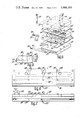
- FIG. 6 is a top view of a slightly modified applicator
- FIG. 7 is a front view of the applicator of FIG. 6.
- FIG. 8 is a side view of the applicator of FIGS. 6 and 7.
- glass fibers or filaments 10 are attenuated from a bushing 12 and are then coated with suitable coating material or size at an applicator 14. Coated filaments 16 are then collected or gathered into a strand 18 by a gathering wheel or shoe 20. The strand 18 is then wound into a package 22 on a collet 24 of a winder 26 having a level winding device 28 thereon, as is well known in the art.
- the bushing 12 can be of any suitable design and, as shown, includes platinum-alloy side walls 30 and end walls 32 which are heated electrically through ears 34.
- the bushing includes an elongate bottom wall 36 of a platinum-alloy having a multiplicity of bushing tips 38 forming orifices through which molten glass flows and from which the filaments 10 are attenuated. As shown, the orifices form a rectangular pattern with the tips 38 located in several parallel rows extending longitudinally of the bushing bottom 36.
- the coating material or size applicator 14 includes a main housing 40 having an upper housing section 42, an intermediate housing section 44, and a lower housing section 46.
- the applicator further includes an upper shim or separator plate 48 and a lower shim or separator plate 50 which are located between the upper housing section 42 and the intermediate housing section 44, and between the intermediate housing section 44 and the lower housing section 46, respectively.
- the housing sections and the shims are held in assembled relationship by machine screws 52 which extend through cylindrical openings 54 and 56 in the housing sections 42 and 44 and into threaded or tapped openings 58 in the lower section 46.
- the housing 40 has three chambers therein including an inlet chamber 60, an intermediate chamber 62, and an outlet chamber 64. These are formed by three openings in the intermediate housing section 44 which cooperate with planar inwardly-facing surfaces on the upper section 42 and the lower section 46.
- the inlet chamber 60 communicates with the intermediate chamber 62 through a lower horizontal passage 66.
- the passage 66 is formed by a baffle or wall 68 in the intermediate housing section 44 which is spaced from the inner surface of the lower section 46 by the shim 50 and specifically by an opening 70 in the shim 50.
- the intermediate chamber 62 communicates with the outlet chamber 64 by an upper horizontally-extending passage 72.
- the outlet chamber 64 also has an outlet passage 78 connecting the outlet chamber 64 with the forward face of the housing 40 just above a horizontally-extending groove 80 therein.
- the passage 78 is formed between adjacent planar surfaces of the housing sections 44 and 46 and by a notch or opening 82 in the shim 50.
- An elongate filament-coating member in the form of a bar or rod 84 is positioned in the groove 80 and, in this instance, is releasably held by metal spring clips 86 fastened to the intermediate housing sections 44 by screws 88.
- the coating bar 84 preferably is of graphite or similar carbon-containing material.
- the bar 84 has a multiplicity of transversely-extending grooves or notches 90 which receive the individual filaments 10 when applying coating material thereto. The bar 84 thereby maintains the filaments 10 physically separated during coating, with the filaments being separated until they are collected by the gathering wheel 20.
- the filaments cannot tend to pull together and collect into bundles or small strands thereof which they otherwise have a tendency to do in the absence of any physical separation by the applicator 14. Further, it is not necessary that there be one of the filaments 10 in each of the grooves 90 and, in fact, the applicator 14 frequently is designed so that the number of the grooves 90 greatly exceeds the number of the filaments 10 so as to help assure that there will be no more than one filament in any one groove.
- the grooves 90 are formed by a spiral thread on the rod 84 which can be made by any conventional machining process. The thread enables the grooves to be formed inexpensively to contribute to the overall low cost of the applicator 14.
- liquid coating material can be supplied by a suitable metering pump to an inlet opening 92 in the upper housing section 42, the opening communicating with the inlet chamber 60.
- the coating material flows down through the chamber 60, through the lower passage 66, and up through the intermediate chamber 62 to the upper passage 72.
- the coating material flows down through the outlet chamber 64 and through the lower passage 78 to the coating bar 84 where the coating material flows over the bar and down into the grooves 90.
- the passages 66, 72, and 78 are designed to provide some back pressure for the coating material in the three chambers 60, 62, and 64, which assures that the coating material will be supplied uniformly through the passage 78 and over the entire bar 84, with the coating material then being supplied to each of the grooves 90 so that each of the filaments 10 will be fully coated.
- the tortuous path of the coating material entering the opening 92 causes any air trapped therein to be separated therefrom and collected particularly in the upper portion of the chamber 60.
- the parth having at least one downwardly-extending portion and preferably an inverted U-shaped portion as the material flows up through the outlet chamber 64, it is virtually assured that any air trapped will be separated before the coating material reaches the coating bar 84.
- the chamber 60 can have a suitable valve-controlled vent 94 which can be periodically opened to expel or vent air collected in the chamber 60.
- fibrous material 95 such as a mass of heterogeneously-disposed glass fibers, can be employed in the chamber 60, if desired, to further aid in separating the air from the coating material.
- the fibrous material can also be located in the chamber 62 to trap additional air, if necessary, in which case the chamber 62 can also have a vent. It is also possible to place the fibrous material in a supply line upstream of the applicator 14 rather than in the applicator. The chambers in the applicator can then be reduced in size although a tortuous path is still desirable for the coating material to maintain back pressure.
- coating materials having a wide range of viscosities can be employed with the applicator 14.
- a size having a viscosity from 50 to 3,000 cps can be employed satisfactorily in the coating material applicator 14 by the use of different shims of suitable thicknesses.
- coating material having low viscosity can have shims as thin as one mil or thinner while coating material with high viscosity can have shims as thick as 10 mils.
- the shims can be readily selected to provide a back pressure of the coating material in the chambers 60, 62, and 64 to assure uniform flow through the passages in the applicator to the filament-coating bar 84.
- FIGS. 6-8 A slightly modified coating material applicator 96 is shown in FIGS. 6-8.
- the applicator includes a main housing 98 having an upper housing section 100 and an intermediate housing section 102, and a lower housing section 104.
- the housing 98 is much longer than the housing 40 and is capable of coating a much wider fan of filaments being attenuated from a bushing.
- the applicator further includes an upper shim or separator plate 106 and a lower shim or separator plate 108 which are located between the upper housing section 100 and the intermediate housing section 102, and between the intermediate housing section 102 and the lower housing section 104, respectively.
- the housing sections and shims are held in assembled relationship by machine screws 110 which extend through cylindrical openings in the housing sections 100 and 102 and into threaded or tapped openings in the lower section 104, similar to the arrangement for the applicator 14.
- the housing 98 has three chambers therein, including an inlet chamber 112, an intermediate chamber 114, and an outlet chamber 116, similar to those of the applicator 14. These are formed by the three housing sections 100, 102, and 104 in the same manner as the applicator 14 and will not be discussed in detail.
- the three chambers are connected by passages similar to those of the applicator 14, with the supply chamber 112 communicating with the intermediate chamber 114 through a lower horizontal passage and with the intermediate chamber 114 communicating with the outlet chamber 116 through an upper horizontal passage, these passages being formed by the housing sections and the shims, as before.
- the outlet chamber 116 also has a lower, horizontal outlet passage connecting the chamber 116 with the forward face of the housing 98 just above a horizontally-extending groove 118 therein.
- a filament-coating bar or rod 120 is positioned in the groove 118 and, in this instance, is releasably held by a putty-like compound at the back of the rod which does not fully harden so that the rod can be readily replaced, when desired.
- the rod 120 again is preferably of graphite or similar carbon-containing material and has transversely-extending grooves or notches 122 which receive the individual filaments 10 when applying coating material thereto. The rod thereby maintains the filament separate and prevents them from pulling together at the applicator.
- the grooves again can be formed by a spiral thread on the rod to provide an inexpensive applicator.
- the applicator 96 has three inlet openings 124 communicating with the inlet chamber 112.
- the coating material thus can be supplied through any one of the openings 124 to accommodate the particular installation. Further, especially when lower viscosity coating materials are employed, all three of the inlet openings 124 can be used to supply the material more uniformly to the inlet chamber 112 so that it correspondingly moves more uniformly through the other chambers and to the rod 120.
- the flow of the coating material through the applicator 96 is similar to that of the applicator 14 with air in the coating material being separated therefrom and collected in the chamber 112.
- a mass of heterogeneously-disposed glass fibers can also be employed in this chamber and in the chamber 114, if desired.
- a vent 126 can be used in either or both chambers to vent the air therefrom periodically.
Landscapes
- Engineering & Computer Science (AREA)
- Textile Engineering (AREA)
- Coating Apparatus (AREA)
- Application Of Or Painting With Fluid Materials (AREA)
Abstract
Description
Claims (25)
Priority Applications (1)
| Application Number | Priority Date | Filing Date | Title |
|---|---|---|---|
| US05/557,735 US3998183A (en) | 1975-03-12 | 1975-03-12 | Coating material applicator |
Applications Claiming Priority (1)
| Application Number | Priority Date | Filing Date | Title |
|---|---|---|---|
| US05/557,735 US3998183A (en) | 1975-03-12 | 1975-03-12 | Coating material applicator |
Publications (1)
| Publication Number | Publication Date |
|---|---|
| US3998183A true US3998183A (en) | 1976-12-21 |
Family
ID=24226682
Family Applications (1)
| Application Number | Title | Priority Date | Filing Date |
|---|---|---|---|
| US05/557,735 Expired - Lifetime US3998183A (en) | 1975-03-12 | 1975-03-12 | Coating material applicator |
Country Status (1)
| Country | Link |
|---|---|
| US (1) | US3998183A (en) |
Cited By (1)
| Publication number | Priority date | Publication date | Assignee | Title |
|---|---|---|---|---|
| US4253416A (en) * | 1979-07-02 | 1981-03-03 | Monsanto Company | Metered finish |
Citations (11)
| Publication number | Priority date | Publication date | Assignee | Title |
|---|---|---|---|---|
| US2066780A (en) * | 1932-01-30 | 1937-01-05 | Armstrong Cork Co | Apparatus for and method of coating fabrics |
| US2373078A (en) * | 1943-02-16 | 1945-04-03 | Owens Corning Fiberglass Corp | Guide for glass and the like fibers |
| US2772518A (en) * | 1952-11-10 | 1956-12-04 | Owens Corning Fiberglass Corp | Method of coating glass filaments with metal |
| US2934458A (en) * | 1953-05-21 | 1960-04-26 | Goodrich Co B F | Method for coating filaments of glass |
| US3384272A (en) * | 1966-09-30 | 1968-05-21 | North American Rockwell | Liquid expulsion device |
| US3507250A (en) * | 1967-11-22 | 1970-04-21 | Monsanto Co | Liquid applicator |
| US3716023A (en) * | 1971-07-15 | 1973-02-13 | Anaconda Wire & Cable Co | Latex applicator |
| US3718117A (en) * | 1971-04-26 | 1973-02-27 | Armstrong Cork Co | Grooved rod coater |
| US3758329A (en) * | 1971-05-24 | 1973-09-11 | Owens Corning Fiberglass Corp | Tsoftenable material method of coating metal glass or synthetic resin filaments with a hea |
| US3780699A (en) * | 1972-11-06 | 1973-12-25 | R Kime | Filament coating apparatus |
| US3827397A (en) * | 1971-06-29 | 1974-08-06 | F Hebberling | Apparatus for coating moving filamentary strands |
-
1975
- 1975-03-12 US US05/557,735 patent/US3998183A/en not_active Expired - Lifetime
Patent Citations (11)
| Publication number | Priority date | Publication date | Assignee | Title |
|---|---|---|---|---|
| US2066780A (en) * | 1932-01-30 | 1937-01-05 | Armstrong Cork Co | Apparatus for and method of coating fabrics |
| US2373078A (en) * | 1943-02-16 | 1945-04-03 | Owens Corning Fiberglass Corp | Guide for glass and the like fibers |
| US2772518A (en) * | 1952-11-10 | 1956-12-04 | Owens Corning Fiberglass Corp | Method of coating glass filaments with metal |
| US2934458A (en) * | 1953-05-21 | 1960-04-26 | Goodrich Co B F | Method for coating filaments of glass |
| US3384272A (en) * | 1966-09-30 | 1968-05-21 | North American Rockwell | Liquid expulsion device |
| US3507250A (en) * | 1967-11-22 | 1970-04-21 | Monsanto Co | Liquid applicator |
| US3718117A (en) * | 1971-04-26 | 1973-02-27 | Armstrong Cork Co | Grooved rod coater |
| US3758329A (en) * | 1971-05-24 | 1973-09-11 | Owens Corning Fiberglass Corp | Tsoftenable material method of coating metal glass or synthetic resin filaments with a hea |
| US3827397A (en) * | 1971-06-29 | 1974-08-06 | F Hebberling | Apparatus for coating moving filamentary strands |
| US3716023A (en) * | 1971-07-15 | 1973-02-13 | Anaconda Wire & Cable Co | Latex applicator |
| US3780699A (en) * | 1972-11-06 | 1973-12-25 | R Kime | Filament coating apparatus |
Cited By (1)
| Publication number | Priority date | Publication date | Assignee | Title |
|---|---|---|---|---|
| US4253416A (en) * | 1979-07-02 | 1981-03-03 | Monsanto Company | Metered finish |
Similar Documents
| Publication | Publication Date | Title |
|---|---|---|
| EP0635077B1 (en) | Apparatus and method for producing a web of thermoplastic filaments | |
| EP0048018A1 (en) | Yarn finish applicator and method for applying finish to a continous filament yarn | |
| US3998183A (en) | Coating material applicator | |
| US2516268A (en) | Apparatus for the treatment of filaments in continuous bundles with liquid | |
| US3765818A (en) | High speed wet spinning technique | |
| US3594228A (en) | Colouring of sheathed continuous strands | |
| US2333699A (en) | Manufacture of rubber threads | |
| US4388057A (en) | Device for the continuous application of liquid finish to a spinneret | |
| US5372004A (en) | Cooling plate of a texturing machine | |
| EP0384886B1 (en) | Stretching chamber | |
| AT397242B (en) | METHOD AND DEVICE FOR THE PRODUCTION OF GLASS FIBER PRODUCTS, e.g. nonwovens, mats, yarns and rovings | |
| US4294189A (en) | Apparatus for coating wires with paint | |
| US3507250A (en) | Liquid applicator | |
| US4775434A (en) | Resin-stripping die | |
| CN1748050B (en) | Device for wetting running filaments | |
| JPH09500858A (en) | Device for supplying liquid to the yarn group | |
| US2690663A (en) | Apparatus for separating liquid from running strands | |
| US6033609A (en) | Device and method to prevent spinneret hole contamination | |
| US2848354A (en) | Yarn treating process and apparatus | |
| US2731667A (en) | Wet spinning apparatus | |
| EP0468918A1 (en) | Fluid-drawing system with variable breaking effect | |
| EP0120674B1 (en) | An improved apparatus for wetting filaments | |
| US2705881A (en) | Liquid applicator for strand | |
| JP2003286613A (en) | Method for applying finish oil and apparatus for applying finish oil | |
| US3199492A (en) | Apparatus for applying a liquid conditioning agent to a thin layer of substantially parallel filaments |
Legal Events
| Date | Code | Title | Description |
|---|---|---|---|
| AS | Assignment |
Owner name: WILMINGTON TRUST COMPANY, ONE RODNEY SQUARE NORTH, Free format text: SECURITY INTEREST;ASSIGNOR:OWENS-CORNING FIBERGLAS CORPORATION;REEL/FRAME:004652/0351 Effective date: 19861103 Owner name: WADE, WILLIAM, J., ONE RODNEY SQUARE NORTH, WILMIN Free format text: SECURITY INTEREST;ASSIGNOR:OWENS-CORNING FIBERGLAS CORPORATION;REEL/FRAME:004652/0351 Effective date: 19861103 Owner name: WILMINGTON TRUST COMPANY, DELAWARE Free format text: SECURITY INTEREST;ASSIGNOR:OWENS-CORNING FIBERGLAS CORPORATION;REEL/FRAME:004652/0351 Effective date: 19861103 Owner name: WADE, WILLIAM, J., DELAWARE Free format text: SECURITY INTEREST;ASSIGNOR:OWENS-CORNING FIBERGLAS CORPORATION;REEL/FRAME:004652/0351 Effective date: 19861103 |
|
| AS | Assignment |
Owner name: OWENS-CORNING FIBERGLAS CORPORATION, FIBERGLAS TOW Free format text: TERMINATION OF SECURITY AGREEMENT RECORDED NOV. 13, 1986. REEL 4652 FRAMES 351-420;ASSIGNORS:WILMINGTON TRUST COMPANY, A DE. BANKING CORPORATION;WADE, WILLIAM J. (TRUSTEES);REEL/FRAME:004903/0501 Effective date: 19870730 Owner name: OWENS-CORNING FIBERGLAS CORPORATION, A CORP. OF DE Free format text: TERMINATION OF SECURITY AGREEMENT RECORDED NOV. 13, 1986. REEL 4652 FRAMES 351-420;ASSIGNORS:WILMINGTON TRUST COMPANY, A DE. BANKING CORPORATION;WADE, WILLIAM J. (TRUSTEES);REEL/FRAME:004903/0501 Effective date: 19870730 |
|
| AS | Assignment |
Owner name: OWENS-CORNING FIBERGLAS TECHNOLOGY INC., ILLINOIS Free format text: ASSIGNMENT OF ASSIGNORS INTEREST.;ASSIGNOR:OWENS-CORNING FIBERGLAS CORPORATION, A CORP. OF DE;REEL/FRAME:006041/0175 Effective date: 19911205 |