US4184366A - Coin testing apparatus - Google Patents
Coin testing apparatus Download PDFInfo
- Publication number
- US4184366A US4184366A US05/918,805 US91880578A US4184366A US 4184366 A US4184366 A US 4184366A US 91880578 A US91880578 A US 91880578A US 4184366 A US4184366 A US 4184366A
- Authority
- US
- United States
- Prior art keywords
- coin
- predetermined
- electrodes
- testing apparatus
- electrode
- Prior art date
- Legal status (The legal status is an assumption and is not a legal conclusion. Google has not performed a legal analysis and makes no representation as to the accuracy of the status listed.)
- Expired - Lifetime
Links
Images


Classifications
-
- G—PHYSICS
- G07—CHECKING-DEVICES
- G07D—HANDLING OF COINS OR VALUABLE PAPERS, e.g. TESTING, SORTING BY DENOMINATIONS, COUNTING, DISPENSING, CHANGING OR DEPOSITING
- G07D5/00—Testing specially adapted to determine the identity or genuineness of coins, e.g. for segregating coins which are unacceptable or alien to a currency
- G07D5/02—Testing the dimensions, e.g. thickness, diameter; Testing the deformation
-
- G—PHYSICS
- G07—CHECKING-DEVICES
- G07D—HANDLING OF COINS OR VALUABLE PAPERS, e.g. TESTING, SORTING BY DENOMINATIONS, COUNTING, DISPENSING, CHANGING OR DEPOSITING
- G07D5/00—Testing specially adapted to determine the identity or genuineness of coins, e.g. for segregating coins which are unacceptable or alien to a currency
- G07D5/08—Testing the magnetic or electric properties
Definitions
- This invention relates to coin testing apparatus which may be used, for example, to test coins tendered for the operation of vending machines, telephone coin-boxes or other coin-freed apparatus.
- Coin testing apparatus is known. Earlier apparatus was essentially mechanical in operation and therefore complex, expensive to manufacture, and not very reliable. More recently, electronic coin testing apparatus has become available. Electronic apparatus now on the market is subject to a number of disadvantages. One such disadvantage is that the apparatus is designed to test coins on the move, which means that the apparatus must be of relatively complex design.
- a known electronic apparatus employs light emitting diodes (LEDs) and photosensors in carrying out checks on coins.
- LEDs light emitting diodes
- a disadvantage of this arrangement is that dirt tends to gather on the LEDs thereby blocking the emission of light, whereby the apparatus fails to function correctly and has to be stripped down and cleaned.
- One object of the invention is to provide a simple and reliable electronic coin testing apparatus.
- Another object of the invention is to provide a coin testing apparatus in which coins to be tested are stopped while a testing operation is carried out, thereby simplifying the design of the apparatus.
- a further object of the invention is to provide a coin testing apparatus in which the operative testing elements are not directly exposed to coins to be tested, whereby dirt from the coins cannot accumulate thereon to adversely affect operation.
- the inventive apparatus carries out a capacitative test of the diameter of the inserted coin.
- the apparatus comprises a member of dielectric material having a first surface against which in use, a coin can rest, at least two spaced electrodes disposed on a second surface of the member opposite the first surface and positioned such that when a coin of predetermined diameter rests against the first surface in a predetermined position a first of the electrodes will be opposite a position on the first surface within the periphery of the coin and a second of the electrodes will be opposite a position on the first surface outside of the periphery of the coin, a planar conductive member arranged on the second surface, and capacitance monitoring means connected to the first and second electrodes and operative to monitor the capacities between the first and second electrodes and the planar conductive member and responsive to the capacities differing by more than a predetermined amount to provide an output signal indicating that a coin of the predetermined diameter is in the predetermined position.
- the apparatus may be designed to test only for coins of one predetermined diameter, in which case only two electrodes are needed. Normally, however, the apparatus will be designed to test coins of a plurality of different predetermined diameters, for example some or all of the coins of a particular currency (e.g. U.S., British, French, Canadian, Japanese, etc). In this case the number of and positioning of the electrodes will be such that, for each predetermined coin diameter, two of the electrodes will be disposed as set forth above.
- a particular currency e.g. U.S., British, French, Canadian, Japanese, etc.
- composition and thickness tests are carried out as well as the diameter check set forth above.
- a particular coin in a particular currency will generally be of a predetermined diameter, composition and thickness. All three tests are carried out while a coin is stopped in the said predetermined position. Output signals provided as a result of all three tests are passed to gating circuitry. Only if the three output signals indicate that the diameter, composition and thickness all correspond to a particular type of coin for which the apparatus is designed to test will the gating circuitry enable acceptance of the coin.
- FIG. 1 is a partial front view of a coin testing apparatus embodying the invention
- FIG. 2 is a somewhat schematic side view of the structure depicted in FIG. 1, the view being mainly sectional along the line II--II in FIG. 1;
- FIG. 3 is a side view, taken in the direction of the arrow III in FIG. 1, of part of the structure shown in FIGS. 1 and 2;
- FIG. 4 is a section along the line IV--IV in FIG. 2;
- FIG. 5 is a schematic circuit diagram of a capacitance monitoring circuit forming part of the apparatus embodying the invention.
- FIG. 6 is a schematic circuit diagram of a coin composition monitoring circuit forming part of the apparatus embodying the invention
- FIG. 7 is a schematic circuit diagram of a coin thickness monitoring circuit forming part of the apparatus embodying the invention.
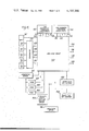
- FIG. 8 is an overall block diagram of the apparatus.
- the illustrated apparatus comprises a face place 10 having therein a coin insertion slot 12 and a coin reject slot 14 provided with a bar 16 for holding rejected coins in place.
- a coin runway 18 constituted by a wall 20 and by a floor 22.
- the runway 18 is not only inclined downwardly, but is also inclined to one side so that the wall 20 is inclined with respect to a vertical plane.
- a coin accept chute 24 extends downwardly from the lower end of the runway 18.
- a coin reject chute 26 leads downwardly from a position part way along the runway 18 to the coin reject slot 16.
- Part of the floor 22 of the runway 18 is constituted by a coin reject flap 28 pivotable out through the side of the runway about an axis parallel to the runway from a closed position shown in FIG. 4 to an open position in which the runway is open to the reject chute 26.
- a coin accept flap 32 is disposed in the runway 18 and is pivotable out of the side of the runway about an axis 33 (FIG. 2) parallel to the runway from a closed position shown in FIG. 2 to an open position opening the runway to the accept chute 24. With the accept flap 32 in the closed position, a coin C inserted through the slot 12 will roll down the runway 18 and be stopped in the position shown in FIGS. 2 and 3 when it abuts the accept flap. The rim of the coin is then in contact with the reject flap 28.
- the accept flap 32 is pivoted to its open position the coin will roll on and drop down the accept chute 24, whereas if, instead, the reject flap 28 is pivoted to its open position, the coin will roll down the reject chute 26 and emerge from the reject slot 14 to be retained by the bar 16.
- a capacitative sensor 34 (FIG. 2) is mounted just inside the runway 18.
- a second capacitative sensor 36 (FIG. 2) is mounted inside the accept chute 24.
- the board 38 is, as shown, disposed at the above-mentioned stopping position of the coin C, so that the coin rests, under the effect of gravity, against the inclined surface 42 of the board 38.
- the surface 44 of the board 38 opposite the surface 42 has etched or printed thereon a group of five spaced arcuate metallic electrodes 46.
- Each electrode 46 is in the form of a strip approximately 1 mm wide (in the radial sense) and 2 mm long (in the circumferential sense).
- a further arcuate metallic reference electrode 48 is also etched or printed on the surface 44, in this case near the accept flap 32.
- the remainder of the surface 44 is provided with a metallic coating 49 connected to ground to constitute a ground plane shown cross-hatched in FIG. 3, the coating being spaced from each of the electrodes 46 and 48 by about 1 mm.
- the number and positioning of the electrodes 46 is determined in accordance with the diameters of predetermined coins to be tested by the apparatus such that the periphery of each coin will, when the coin is stopped against the accept flap 32, be disposed opposite and between two of the electrodes 46, as shown in FIG. 3.
- at least one of the electrodes 46 will be opposite a position on the surface 42 within the periphery of the coin and at least one other of the electrodes 46 will be opposite a position on the surface 42 outside of the periphery of the coin.
- the present apparatus is arranged to distinguish between coins of four different diameters, whereby at least five electrodes 46 are needed.
- a magnetic core 50 is disposed at the above-described stopping position of the coin C.
- the core 50 has an air gap defined between surfaces 52, 54 thereof.
- the surface 52 abuts the surface 44 of the board 38.
- the surface 54 confronts the surface 52 such that the entire air gap will extend through any coin of permitted size stopped at the above-described stopping position.
- a sheet 56 of non-conductive material for instance glass fibre
- Another sheet 58 of non-conductive material lies against the sheet 56 to form a wall of the runway 18 opposite the wall 20.
- a circular metallic electrode 60 is etched or printed on the side of the sheet 58 adjacent the sheet 56 so as to be sandwiched between the sheets 56 and 58.
- a respective, like capacitance monitoring circuit is connected to each of the electrodes 46 and 48.
- the capacitance monitoring circuit for one of the electrodes 46, 48 is shown generally at 70 in FIG. 5.
- the capacitance monitoring circuit comprises a C/MOS gate 72 operating as a Schmitt trigger and having two inputs 74, 75.
- a square wave generator 76 which may be common to all six of the capacitance monitoring means 70, is connected to the inputs 74, 75 to supply thereto square waves of respective opposite phases.
- the input 74 is supplied via a series resistor 78.
- the input 74 is connected to the associated electrode 46 or 48, whereby the capacity to ground of the electrode, shown schematically as a capacitor 80, is connected in circuit as shown in FIG.
- resistor 78 and capacitor 80 constitute an RC timing network.
- the arrangement described so far constitutes a monostable circuit in that the gate 72 produces a pulse at its output on each alternate occasion that the square wave input changes level, the width of the pulse being dependent upon the time constant of the RC network, that is to say upon the capacity of the electrode 46 or 48 to ground.
- a pulse width to voltage converter 82 converts the pulse width to a voltage proportional to the pulse width and therefore also proportional to the capacity to ground of the associated electrode 46 or 48.
- the capacities to ground of those of the electrodes 46 disposed opposite positions within the periphery of the coin will, of course, increase by more than the capacities to ground of the other electrodes 46. Therefore, by comparing the voltages provided by the capacitance monitoring circuits 70 and noting if the capacitances between any two adjacent electrodes 46 differ by more than a predetermined amount one can determine if the diameter of a coin is within a narrow range of values such that it is between the adjacent electrodes and is therefore of a diameter lying within a narrow range corresponding to one of the four acceptable coins. Such comparison operation will be described in more detail hereinbelow.
- the magnetic core 50 described above has a coil 90 wound thereon.
- the core 50 and coil 90 form part of a coin composition monitoring circuit shown generally at 92 in FIG. 6.
- the coil 90 cooperates with a capacitor 94 to form a tuned circuit determining the operating frequency of an oscillator 96.
- the inductance of the coil 90 will change by an amount dependent upon the composition of the coin.
- the permeability of the coin material affects the magnetic flux produced by the coil 90 and flowing around the core 50 and across the air gap
- the resistivity of the coin material affects eddy current losses in the coin.
- Some of the four types of coin may, of course, be of the same composition. However, since coins of the same composition but of different denominations may also be of different thicknesses, each of the four coins will, it is found, cause the oscillator 96 to operate within a respective one of four narrow frequency ranges.
- the nominal or basic operating frequency of the oscillator is chosen to be sufficiently low (e.g. about 400 Hz) so that even the thickest coin to be tested will be completely permeated by the magnetic field of the core 50 traversing the air gap, so that skin effect does not need to be considered.
- the output of the oscillator 96 is passed through a frequency to voltage converter 98, a low pass filter 100 for removing parasitic voltages, and a DC amplifier 102.
- the output of the amplifier 102 will be a DC voltage of a level corresponding to the operating frequency of the oscillator 96, and is passed to four threshold gates 104.
- Each gate 104 is responsive to the voltage from the amplifier 102 lying within a respective narrow predetermined range of values corresponding to a respective one of the four coin types being in the air gap to provide an output signal indicating such on one of four output leads 106, 108, 110 and 112.
- the thickness monitoring circuit used to perform this task is shown generally in FIG. 7 at 120.
- a voltage proportional to the capacitance to ground of the electrode 60 and therefore to the thickness of the coin is produced in a capacity monitoring circuit 122.
- the circuit 122 can be substantially exactly the same as the circuit 70 described with reference to FIG.
- the thickness monitoring circuit 120 further includes a reference circuit 124, which is substantially the same as the circuit 122 except that it monitors the capacitance to ground of a further electrode (not shown) in the apparatus.
- the two voltages from the circuits 122 and 124 are compared in a comparator 126 which may essentially comprise a differential amplifier.
- An advantage of the reference circuit 124 is that undesired effects such as parasitic voltages, drift or the like substantially equally affect the capacities measured by the two circuits 122 and 124 so that such effects are substantially cancelled out in the comparator 126.
- the output voltage from the comparator 126 which is proportional to the capacity to ground of the electrode 60 and therefore to the thickness of the coin under test, is passed to four threshold gates 128.
- Each gate 128 is responsive to the voltage from the comparator 126 lying within a respective narrow predetermined range of values corresponding to the thickness range of a respective one of the four types of coin to provide an output signal indicating the coin type on one of four output leads 130, 132, 134 and 136.
- FIG. 8 An overall block diagram of the apparatus is shown in FIG. 8.
- a main logic circuit 150 described below, has connected thereto, as shown, the coin composition monitoring circuit 92 of FIG. 6, the coin thickness monitoring circuit 120 of FIG. 7, the capacitative sensors 34 and 36, solenoids 152 and 154 for operating the coin accept flap 32 and coin reject flap 28, respectively, a capacitative sensor 156 for sensing the position of the accept flap 32, respective monostable circuits 158, 160 and 162 each triggered by the capacitative sensor 34, leads 164, 166, 168 and 170 connected to a comparator 172, and output terminals 174, 176, 178 and 180.
- the five of the capacitance monitoring circuits 70 connected to the respective five electrodes 46 are connected to the comparator 172.
- the capacitance monitoring circuit connected to the reference electrode 48, referenced 70' in FIG. 8, is also connected to the main logic circuit 150.
- the comparator 172 receives the above-described capacitance-dependent voltages from the circuits 70 and carries out the above-described function of determining if the capacitances between any two adjacent electrodes 46, as represented by the voltages from the circuits 70, differ by more than a predetermined amount to indicate the presence of a coin of one of the four predetermined diameters.
- the comparator 172 may thus essentially comprise four differential amplifiers each connected to an adjacent pair of the circuits 70.
- the comparator 172 signals detection of a coin of one of the four predetermined diameters by applying an output signal to one of the four leads 164, 166, 168 and 170 leading to the main logic circuit 150.
- the main logic circuit 150 principally comprises gating circuitry (not shown) connecting the leads from the monitoring circuits 92 and 120 and from the comparator 172 to the output terminals 174, 176, 178 and 180.
- the gating circuitry essentially comprises four three-input AND gates.
- the monitoring circuits 92, 120 and the comparator 172 apply signals to the leads 106, 130 and 164, respectively, if by their respective associated tests each indicate that a coin of the same one of the four types has been inserted.
- One of the three-input AND gates receives inputs from these leads and applies a signal to the output terminal 174 only if all three tests agree on the type of coin.
- the other three three-input AND gates are connected such that signals are provided on the output terminals 176, 178 and 180 only if all three tests agree that a coin of the second, third or fourth type, respectively, has been inserted.
- the main logic circuit 150 also includes power supply control circuitry and an inhibit circuit, the nature of which will become apparent from the following.
- the apparatus described above functions as follows.
- a coin to be tested is inserted into the insertion slot 12 in the face plate 10, drops on to the runway 18, and starts to roll down the runway.
- the capacitative sensor 34 senses passage of the coin and triggers the three monostable circuits 158, 160 and 162 to produce pulses having respective durations of approximately 150 ms, 400 ms and 1.5 s.
- the capacitative sensor 34 is operative on the reject flap solenoid 154 to close the reject flap 28.
- Energisation of the circuitry is delayed while the monostable circuit 158 is operative to allow sufficient time for the flap to be closed so that movement of the flap will not unsettle the circuitry monitoring changes in capacity. (If a non-conductive disc (i.e. of plastics) is fraudulently inserted the capacitative sensor 34 is not operative as set forth above and the disc is therefore immediately rejected.)
- the coin continues rolling down the runway 18, supported on the reject flap 28, until it is stopped by the accept flap 32.
- the coin then rests, as explained above, against the surface 42 of the board 38.
- the diameter, material composition and thickness of the coin are tested as explained above, provided that the circuit 70' connected to the reference electrode 48 indicates that the coin is properly positioned against the accept flap 32.
- the solenoid 152 is caused to open the accept flap 32 so that the coin continues down the runway 18 and drops into the accept chute 24. The coin then drops past the capacitative sensor 36 and out of the accept chute 24 into the cash box of equipment controlled by the apparatus.
- Energisation of the capacitative sensor 36 by the coin dropping therepast enables the appropriate one of the three-input AND gates to pass its output to the appropriate one of the output terminals 174, 176, 178 and 180 of the main logic circuit 150 to signify that a coin of the appropriate one of the four coin types has been unanimously detected by the tests and that the coin has been accepted.
- the above-mentioned inhibit circuit in the main logic circuit 150 is triggered in the event that all of the tests do not signify that a coin of one type is present. When triggered, for this reason the inhibit circuit prevents opening of the accept flap 32 and causes the solenoid 154 to open the reject flap 28 to reject the coin.
- the inhibit circuit is also triggered if the electronic validation and acceptance procedure has not been completed by the end of the period of the monostable circuit 162 and/or if another coin passes the capacitative sensor 34 prior to the end of the period of the monostable circuit 162. If the accept flap is already open when the inhibit circuit is triggered it will remain open until the inhibit circuit is reset. In this situation, the coin which has been tested will either proceed to the accept chute 24 or will roll into the reject chute 26. The inhibit circuit is reset at the end of the period of the monostable circuit 162.
- the invention can of course be embodied in other ways than that described above by way of example.
- the diameter and thickness testing arrangements could, likewise, be altered to cater for any number of coin types from one up.
- an additional test for example a weight test, could be employed and validated together with the other tests.
- the coin could be arranged to rest on a strip of piezoelectric ceramic material, the voltage output of which would indicate the weight of the coin.
- the validated output signals on the leads 174, 176, 178 and 180 of the main logic circuit 150 can be applied to a variety of uses.
- the signals could, if required, be supplied to an electronic or electromechanical accumulator arranged to add the total amount of money accepted by the apparatus in any one sequence of operation.
- the accumulator could be pre-programmed, for example by means of manual switches, to initiate or enable various operations of equipment controlled by the coin testing apparatus as different money totals are reached.
- the acceptable coin types include coins of greatly differing diameters, it may be necessary to provide at least the further reference electrode 48.
- composition monitoring circuit of FIG. 6 may be modified to monitor percentage changes in the oscillator frequency produced by a coin rather than the absolute value to which the frequency is changed by a coin, whereby it is not necessary to adjust the basic operating frequency of the oscillator 96 to a fixed value, thereby simplifying setting up of the apparatus.
- thickness and diameter monitoring arrangements could be modified to monitor percentage changes of capacitance on arrival of a coin rather than absolute values to which capacitances are changed.
Abstract
Description
Claims (13)
Priority Applications (1)
| Application Number | Priority Date | Filing Date | Title |
|---|---|---|---|
| US05/918,805 US4184366A (en) | 1976-06-08 | 1978-06-26 | Coin testing apparatus |
Applications Claiming Priority (4)
| Application Number | Priority Date | Filing Date | Title |
|---|---|---|---|
| GB23672/76 | 1976-06-08 | ||
| GB2367276A GB1576714A (en) | 1976-06-08 | 1976-06-08 | Coin testing apparatus |
| US80477677A | 1977-06-08 | 1977-06-08 | |
| US05/918,805 US4184366A (en) | 1976-06-08 | 1978-06-26 | Coin testing apparatus |
Related Parent Applications (1)
| Application Number | Title | Priority Date | Filing Date |
|---|---|---|---|
| US80477677A Continuation | 1976-06-08 | 1977-06-08 |
Publications (1)
| Publication Number | Publication Date |
|---|---|
| US4184366A true US4184366A (en) | 1980-01-22 |
Family
ID=27258246
Family Applications (1)
| Application Number | Title | Priority Date | Filing Date |
|---|---|---|---|
| US05/918,805 Expired - Lifetime US4184366A (en) | 1976-06-08 | 1978-06-26 | Coin testing apparatus |
Country Status (1)
| Country | Link |
|---|---|
| US (1) | US4184366A (en) |
Cited By (63)
| Publication number | Priority date | Publication date | Assignee | Title |
|---|---|---|---|---|
| US4323148A (en) * | 1979-03-12 | 1982-04-06 | Matsushita Electric Industrial Co., Ltd. | Coin selector for vending machine |
| EP0051028A2 (en) * | 1980-10-28 | 1982-05-05 | Third Wave Electronics Company, Inc. | Coin acceptor or rejector |
| US4371073A (en) * | 1979-08-08 | 1983-02-01 | Autelca Ag | Coin checker for coins of varying diameter |
| WO1983003154A1 (en) * | 1982-03-04 | 1983-09-15 | Ramseier, Hans | Apparatus for testing coins having different diameters or thicknesses |
| FR2536189A1 (en) * | 1982-11-16 | 1984-05-18 | Gesi | SELECTOR OF COINS OF CURRENCY |
| US4678994A (en) * | 1984-06-27 | 1987-07-07 | Digital Products Corporation | Methods and apparatus employing apparent resonant properties of thin conducting materials |
| US4805754A (en) * | 1985-05-02 | 1989-02-21 | Kabanos Pty. Limited | Coin detection device |
| US4845994A (en) * | 1988-02-29 | 1989-07-11 | Automatic Toll Systems, Inc. | Coin testing apparatus |
| EP0343871A2 (en) * | 1988-05-27 | 1989-11-29 | Kabushiki Kaisha Nippon Conlux | Coin validator |
| EP0349114A2 (en) * | 1988-06-30 | 1990-01-03 | Kabushiki Kaisha Nippon Conlux | Coin validator |
| WO1991016690A1 (en) * | 1990-04-20 | 1991-10-31 | Tetrel Limited | Coin validators |
| US5067604A (en) * | 1988-11-14 | 1991-11-26 | Bally Manufacturing Corporation | Self teaching coin discriminator |
| US5097934A (en) * | 1990-03-09 | 1992-03-24 | Automatic Toll Systems, Inc. | Coin sensing apparatus |
| US5154272A (en) * | 1990-04-18 | 1992-10-13 | Kabushiki Kaisha Nippon Conlux | Controller for an automatic vending machine |
| US5379875A (en) * | 1992-07-17 | 1995-01-10 | Eb Metal Industries, Inc. | Coin discriminator and acceptor arrangement |
| US5392891A (en) * | 1994-02-10 | 1995-02-28 | Raytheon Company | Apparatus and method for discriminating coins based on metal content |
| WO1996005575A1 (en) * | 1994-08-12 | 1996-02-22 | Tetrel Limited | Coin validators |
| US5579887A (en) * | 1995-06-15 | 1996-12-03 | Coin Acceptors, Inc. | Coin detection apparatus |
| GB2308004A (en) * | 1995-12-05 | 1997-06-11 | John Jervis Comfort | Coin recognition apparatus |
| US5988348A (en) * | 1996-06-28 | 1999-11-23 | Coinstar, Inc. | Coin discrimination apparatus and method |
| US6047808A (en) * | 1996-03-07 | 2000-04-11 | Coinstar, Inc. | Coin sensing apparatus and method |
| US6056104A (en) * | 1996-06-28 | 2000-05-02 | Coinstar, Inc. | Coin sensing apparatus and method |
| US6168001B1 (en) | 1997-06-27 | 2001-01-02 | Coinstar, Inc. | Positive drive coin discrimination apparatus and method |
| US6196371B1 (en) | 1996-06-28 | 2001-03-06 | Coinstar, Inc. | Coin discrimination apparatus and method |
| US20020126885A1 (en) * | 1996-05-13 | 2002-09-12 | Mennie Douglas U. | Automatic funds processing system |
| WO2002077932A1 (en) * | 2001-03-22 | 2002-10-03 | Scan Coin Industries Ab | A coin discriminating device and method, and a coin handling machine including such a device and method |
| US6471030B1 (en) * | 1996-06-28 | 2002-10-29 | Coinstar, Inc. | Coin sensing apparatus and method |
| US20030057054A1 (en) * | 2001-09-21 | 2003-03-27 | Waechter Mark L. | Method and apparatus for coin or object sensing using adaptive operating point control |
| US6668999B2 (en) * | 2000-08-30 | 2003-12-30 | Asahi Seiko Co., Ltd. | Coin sensor |
| US6755730B2 (en) | 2002-03-11 | 2004-06-29 | Cummins-Allison Corp. | Disc-type coin processing device having improved coin discrimination system |
| US6766892B2 (en) | 1996-06-28 | 2004-07-27 | Coinstar, Inc. | Coin discrimination apparatus and method |
| US20050040007A1 (en) * | 2002-03-11 | 2005-02-24 | Geib Joseph J. | Coin processing machine and method for discriminating coins of varied composition, thickness, and diameter |
| US20050051409A1 (en) * | 2001-11-05 | 2005-03-10 | Geoffrey Howells | Coin discriminator where frequencies of eddy currents are measured |
| US20060151284A1 (en) * | 2003-09-24 | 2006-07-13 | Geoffrey Howells | Coin discriminators |
| US20060175176A1 (en) * | 2005-02-10 | 2006-08-10 | Blake John R | Method and apparatus for varying coin-processing machine receptacle limits |
| US20090087076A1 (en) * | 2000-02-11 | 2009-04-02 | Cummins-Allison Corp. | System and method for processing currency bills and tickets |
| US20090239459A1 (en) * | 2008-03-19 | 2009-09-24 | Cummins-Allison Corp. | Self Service Coin Processing Machines With EPOS Terminal And Method For Automated Payout Utilizing Same |
| JP2013025750A (en) * | 2011-07-26 | 2013-02-04 | Nippon Conlux Co Ltd | Coin tube equipped with coin number counting means |
| US8393455B2 (en) | 2003-03-12 | 2013-03-12 | Cummins-Allison Corp. | Coin processing device having a moveable coin receptacle station |
| USRE44252E1 (en) | 2002-01-10 | 2013-06-04 | Cummins-Allison Corp. | Coin redemption system |
| US8523641B2 (en) | 2004-09-15 | 2013-09-03 | Cummins-Allison Corp. | System, method and apparatus for automatically filling a coin cassette |
| US8545295B2 (en) | 2010-12-17 | 2013-10-01 | Cummins-Allison Corp. | Coin processing systems, methods and devices |
| US8559694B2 (en) | 2005-10-05 | 2013-10-15 | Cummins-Allison Corp. | Currency processing system with fitness detection |
| USRE44689E1 (en) | 2002-03-11 | 2014-01-07 | Cummins-Allison Corp. | Optical coin discrimination sensor and coin processing system using the same |
| US8959029B2 (en) | 2006-03-23 | 2015-02-17 | Cummins-Allison Corp | System, apparatus, and methods for currency processing control and redemption |
| US8967361B2 (en) | 2013-02-27 | 2015-03-03 | Outerwall Inc. | Coin counting and sorting machines |
| US9022841B2 (en) | 2013-05-08 | 2015-05-05 | Outerwall Inc. | Coin counting and/or sorting machines and associated systems and methods |
| US9036890B2 (en) | 2012-06-05 | 2015-05-19 | Outerwall Inc. | Optical coin discrimination systems and methods for use with consumer-operated kiosks and the like |
| US9092924B1 (en) | 2012-08-31 | 2015-07-28 | Cummins-Allison Corp. | Disk-type coin processing unit with angled sorting head |
| US9235945B2 (en) | 2014-02-10 | 2016-01-12 | Outerwall Inc. | Coin input apparatuses and associated methods and systems |
| US9430893B1 (en) | 2014-08-06 | 2016-08-30 | Cummins-Allison Corp. | Systems, methods and devices for managing rejected coins during coin processing |
| US9501885B1 (en) | 2014-07-09 | 2016-11-22 | Cummins-Allison Corp. | Systems, methods and devices for processing coins utilizing near-normal and high-angle of incidence lighting |
| US9508208B1 (en) | 2014-07-25 | 2016-11-29 | Cummins Allison Corp. | Systems, methods and devices for processing coins with linear array of coin imaging sensors |
| US9818249B1 (en) | 2002-09-04 | 2017-11-14 | Copilot Ventures Fund Iii Llc | Authentication method and system |
| US9875593B1 (en) | 2015-08-07 | 2018-01-23 | Cummins-Allison Corp. | Systems, methods and devices for coin processing and coin recycling |
| US9916713B1 (en) | 2014-07-09 | 2018-03-13 | Cummins-Allison Corp. | Systems, methods and devices for processing coins utilizing normal or near-normal and/or high-angle of incidence lighting |
| US9934640B2 (en) | 2004-09-15 | 2018-04-03 | Cummins-Allison Corp. | System, method and apparatus for repurposing currency |
| CN108022359A (en) * | 2016-10-28 | 2018-05-11 | 山东新北洋信息技术股份有限公司 | Coin cleaning-sorting machine kicks coin control method and device |
| US10089812B1 (en) | 2014-11-11 | 2018-10-02 | Cummins-Allison Corp. | Systems, methods and devices for processing coins utilizing a multi-material coin sorting disk |
| US10181234B2 (en) | 2016-10-18 | 2019-01-15 | Cummins-Allison Corp. | Coin sorting head and coin processing system using the same |
| US10679449B2 (en) | 2016-10-18 | 2020-06-09 | Cummins-Allison Corp. | Coin sorting head and coin processing system using the same |
| US10685523B1 (en) | 2014-07-09 | 2020-06-16 | Cummins-Allison Corp. | Systems, methods and devices for processing batches of coins utilizing coin imaging sensor assemblies |
| US11443581B2 (en) | 2019-01-04 | 2022-09-13 | Cummins-Allison Corp. | Coin pad for coin processing system |
Citations (3)
| Publication number | Priority date | Publication date | Assignee | Title |
|---|---|---|---|---|
| FR1401488A (en) * | 1964-05-09 | 1965-06-04 | Compteurs De Geneve Soc D | Device for controlling the payment of coins into an automatic machine |
| US3901368A (en) * | 1974-03-11 | 1975-08-26 | Lance T Klinger | Coin acceptor/rejector |
| US3977508A (en) * | 1974-06-19 | 1976-08-31 | Compagnie Generale D'automatisme | Device for recognizing a category of coins |
-
1978
- 1978-06-26 US US05/918,805 patent/US4184366A/en not_active Expired - Lifetime
Patent Citations (3)
| Publication number | Priority date | Publication date | Assignee | Title |
|---|---|---|---|---|
| FR1401488A (en) * | 1964-05-09 | 1965-06-04 | Compteurs De Geneve Soc D | Device for controlling the payment of coins into an automatic machine |
| US3901368A (en) * | 1974-03-11 | 1975-08-26 | Lance T Klinger | Coin acceptor/rejector |
| US3977508A (en) * | 1974-06-19 | 1976-08-31 | Compagnie Generale D'automatisme | Device for recognizing a category of coins |
Cited By (107)
| Publication number | Priority date | Publication date | Assignee | Title |
|---|---|---|---|---|
| US4323148A (en) * | 1979-03-12 | 1982-04-06 | Matsushita Electric Industrial Co., Ltd. | Coin selector for vending machine |
| US4371073A (en) * | 1979-08-08 | 1983-02-01 | Autelca Ag | Coin checker for coins of varying diameter |
| EP0051028A2 (en) * | 1980-10-28 | 1982-05-05 | Third Wave Electronics Company, Inc. | Coin acceptor or rejector |
| EP0051028A3 (en) * | 1980-10-28 | 1982-06-23 | Third Wave Electronics Company, Inc. | Coin acceptor or rejector |
| WO1983003154A1 (en) * | 1982-03-04 | 1983-09-15 | Ramseier, Hans | Apparatus for testing coins having different diameters or thicknesses |
| FR2536189A1 (en) * | 1982-11-16 | 1984-05-18 | Gesi | SELECTOR OF COINS OF CURRENCY |
| EP0109057A2 (en) * | 1982-11-16 | 1984-05-23 | Groupement d'Intérêt Economique régi par l'ordonnance du 23 septembre 1967 dit: GESI | Coin selector |
| EP0109057A3 (en) * | 1982-11-16 | 1985-06-12 | Groupement d'Intérêt Economique régi par l'ordonnance du 23 septembre 1967 dit: GESI | Coin selector |
| US4678994A (en) * | 1984-06-27 | 1987-07-07 | Digital Products Corporation | Methods and apparatus employing apparent resonant properties of thin conducting materials |
| US4805754A (en) * | 1985-05-02 | 1989-02-21 | Kabanos Pty. Limited | Coin detection device |
| EP0316308A1 (en) * | 1985-05-02 | 1989-05-24 | Kabanos Pty. Limited | Coin detection device |
| EP0316308A4 (en) * | 1985-05-02 | 1989-06-21 | Kabanos Pty Ltd | Coin detection device. |
| US4845994A (en) * | 1988-02-29 | 1989-07-11 | Automatic Toll Systems, Inc. | Coin testing apparatus |
| EP0343871A2 (en) * | 1988-05-27 | 1989-11-29 | Kabushiki Kaisha Nippon Conlux | Coin validator |
| EP0343871A3 (en) * | 1988-05-27 | 1990-04-25 | Nippon Conlux Co Ltd | Coin validator |
| US5002174A (en) * | 1988-05-27 | 1991-03-26 | Kabushiki Kaisha Nippon Conlux | Coin validator |
| EP0349114A2 (en) * | 1988-06-30 | 1990-01-03 | Kabushiki Kaisha Nippon Conlux | Coin validator |
| EP0349114A3 (en) * | 1988-06-30 | 1990-04-25 | Kabushiki Kaisha Nippon Conlux | Coin validator |
| US5067604A (en) * | 1988-11-14 | 1991-11-26 | Bally Manufacturing Corporation | Self teaching coin discriminator |
| US5097934A (en) * | 1990-03-09 | 1992-03-24 | Automatic Toll Systems, Inc. | Coin sensing apparatus |
| US5154272A (en) * | 1990-04-18 | 1992-10-13 | Kabushiki Kaisha Nippon Conlux | Controller for an automatic vending machine |
| WO1991016690A1 (en) * | 1990-04-20 | 1991-10-31 | Tetrel Limited | Coin validators |
| US5379875A (en) * | 1992-07-17 | 1995-01-10 | Eb Metal Industries, Inc. | Coin discriminator and acceptor arrangement |
| US5392891A (en) * | 1994-02-10 | 1995-02-28 | Raytheon Company | Apparatus and method for discriminating coins based on metal content |
| WO1996005575A1 (en) * | 1994-08-12 | 1996-02-22 | Tetrel Limited | Coin validators |
| US5579887A (en) * | 1995-06-15 | 1996-12-03 | Coin Acceptors, Inc. | Coin detection apparatus |
| GB2308004A (en) * | 1995-12-05 | 1997-06-11 | John Jervis Comfort | Coin recognition apparatus |
| US6047808A (en) * | 1996-03-07 | 2000-04-11 | Coinstar, Inc. | Coin sensing apparatus and method |
| US20110099105A1 (en) * | 1996-05-13 | 2011-04-28 | Cummins-Allison Corp. | Self-service currency exchange machine |
| US20020126885A1 (en) * | 1996-05-13 | 2002-09-12 | Mennie Douglas U. | Automatic funds processing system |
| US8229821B2 (en) | 1996-05-13 | 2012-07-24 | Cummins-Allison Corp. | Self-service currency exchange machine |
| US6056104A (en) * | 1996-06-28 | 2000-05-02 | Coinstar, Inc. | Coin sensing apparatus and method |
| US6196371B1 (en) | 1996-06-28 | 2001-03-06 | Coinstar, Inc. | Coin discrimination apparatus and method |
| US6471030B1 (en) * | 1996-06-28 | 2002-10-29 | Coinstar, Inc. | Coin sensing apparatus and method |
| US7213697B2 (en) | 1996-06-28 | 2007-05-08 | Coinstar, Inc. | Coin discrimination apparatus and method |
| US20090166151A1 (en) * | 1996-06-28 | 2009-07-02 | Douglas Alan Martin | Coin discrimination apparatus and method |
| US7520374B2 (en) | 1996-06-28 | 2009-04-21 | Coinstar, Inc. | Coin discrimination apparatus and method |
| US5988348A (en) * | 1996-06-28 | 1999-11-23 | Coinstar, Inc. | Coin discrimination apparatus and method |
| US6766892B2 (en) | 1996-06-28 | 2004-07-27 | Coinstar, Inc. | Coin discrimination apparatus and method |
| US20050016815A1 (en) * | 1996-06-28 | 2005-01-27 | Martin Douglas Alan | Coin discrimination apparatus and method |
| US6168001B1 (en) | 1997-06-27 | 2001-01-02 | Coinstar, Inc. | Positive drive coin discrimination apparatus and method |
| US20090087076A1 (en) * | 2000-02-11 | 2009-04-02 | Cummins-Allison Corp. | System and method for processing currency bills and tickets |
| US9129271B2 (en) | 2000-02-11 | 2015-09-08 | Cummins-Allison Corp. | System and method for processing casino tickets |
| US8701857B2 (en) | 2000-02-11 | 2014-04-22 | Cummins-Allison Corp. | System and method for processing currency bills and tickets |
| US8684160B2 (en) | 2000-04-28 | 2014-04-01 | Cummins-Allison Corp. | System and method for processing coins |
| US6668999B2 (en) * | 2000-08-30 | 2003-12-30 | Asahi Seiko Co., Ltd. | Coin sensor |
| WO2002077932A1 (en) * | 2001-03-22 | 2002-10-03 | Scan Coin Industries Ab | A coin discriminating device and method, and a coin handling machine including such a device and method |
| US7490709B2 (en) * | 2001-03-22 | 2009-02-17 | Scan Coin Industries Ab | Coin discriminating device and method, and a coin handling machine including such a device and method |
| US20040129527A1 (en) * | 2001-03-22 | 2004-07-08 | Manfred Jonsson | Coin discriminating device and method, and a coin handling machine including such a device and method |
| US7152727B2 (en) | 2001-09-21 | 2006-12-26 | Coinstar, Inc. | Method and apparatus for coin or object sensing using adaptive operating point control |
| US20030057054A1 (en) * | 2001-09-21 | 2003-03-27 | Waechter Mark L. | Method and apparatus for coin or object sensing using adaptive operating point control |
| US20050051409A1 (en) * | 2001-11-05 | 2005-03-10 | Geoffrey Howells | Coin discriminator where frequencies of eddy currents are measured |
| US7537099B2 (en) | 2001-11-05 | 2009-05-26 | Scan Coin Industries Ab | Coin discriminator where frequencies of eddy currents are measured |
| USRE44252E1 (en) | 2002-01-10 | 2013-06-04 | Cummins-Allison Corp. | Coin redemption system |
| US6755730B2 (en) | 2002-03-11 | 2004-06-29 | Cummins-Allison Corp. | Disc-type coin processing device having improved coin discrimination system |
| US20050045450A1 (en) * | 2002-03-11 | 2005-03-03 | Geib Joseph J. | Sensor and method for discriminating coins using fast fourier transform |
| US6892871B2 (en) | 2002-03-11 | 2005-05-17 | Cummins-Allison Corp. | Sensor and method for discriminating coins of varied composition, thickness, and diameter |
| US7552810B2 (en) | 2002-03-11 | 2009-06-30 | Cummins-Allison Corp. | Sensor and method for discriminating coins using fast fourier transform |
| US6988606B2 (en) | 2002-03-11 | 2006-01-24 | Cummins-Allison Corp. | Coin processing machine and method for discriminating coins of varied composition, thickness, and diameter |
| US20050040007A1 (en) * | 2002-03-11 | 2005-02-24 | Geib Joseph J. | Coin processing machine and method for discriminating coins of varied composition, thickness, and diameter |
| USRE44689E1 (en) | 2002-03-11 | 2014-01-07 | Cummins-Allison Corp. | Optical coin discrimination sensor and coin processing system using the same |
| US9818249B1 (en) | 2002-09-04 | 2017-11-14 | Copilot Ventures Fund Iii Llc | Authentication method and system |
| US8393455B2 (en) | 2003-03-12 | 2013-03-12 | Cummins-Allison Corp. | Coin processing device having a moveable coin receptacle station |
| US7584833B2 (en) | 2003-09-24 | 2009-09-08 | Scancoin Industries Ab | Coin discriminators |
| US20060151284A1 (en) * | 2003-09-24 | 2006-07-13 | Geoffrey Howells | Coin discriminators |
| US8523641B2 (en) | 2004-09-15 | 2013-09-03 | Cummins-Allison Corp. | System, method and apparatus for automatically filling a coin cassette |
| US9934640B2 (en) | 2004-09-15 | 2018-04-03 | Cummins-Allison Corp. | System, method and apparatus for repurposing currency |
| US20060175176A1 (en) * | 2005-02-10 | 2006-08-10 | Blake John R | Method and apparatus for varying coin-processing machine receptacle limits |
| US8602200B2 (en) | 2005-02-10 | 2013-12-10 | Cummins-Allison Corp. | Method and apparatus for varying coin-processing machine receptacle limits |
| US8684159B2 (en) | 2005-02-10 | 2014-04-01 | Cummins-Allison Corp. | Method and apparatus for varying coin-processing machine receptacle limits |
| US8559694B2 (en) | 2005-10-05 | 2013-10-15 | Cummins-Allison Corp. | Currency processing system with fitness detection |
| US8959029B2 (en) | 2006-03-23 | 2015-02-17 | Cummins-Allison Corp | System, apparatus, and methods for currency processing control and redemption |
| US20090239459A1 (en) * | 2008-03-19 | 2009-09-24 | Cummins-Allison Corp. | Self Service Coin Processing Machines With EPOS Terminal And Method For Automated Payout Utilizing Same |
| US8701860B1 (en) | 2010-12-17 | 2014-04-22 | Cummins-Allison Corp. | Coin processing systems, methods and devices |
| US9437069B1 (en) | 2010-12-17 | 2016-09-06 | Cummins-Allison Corp. | Coin processing systems, methods and devices |
| US9830762B1 (en) | 2010-12-17 | 2017-11-28 | Cummins-Allison Corp. | Coin processing methods |
| US8545295B2 (en) | 2010-12-17 | 2013-10-01 | Cummins-Allison Corp. | Coin processing systems, methods and devices |
| JP2013025750A (en) * | 2011-07-26 | 2013-02-04 | Nippon Conlux Co Ltd | Coin tube equipped with coin number counting means |
| US9036890B2 (en) | 2012-06-05 | 2015-05-19 | Outerwall Inc. | Optical coin discrimination systems and methods for use with consumer-operated kiosks and the like |
| US9594982B2 (en) | 2012-06-05 | 2017-03-14 | Coinstar, Llc | Optical coin discrimination systems and methods for use with consumer-operated kiosks and the like |
| US9092924B1 (en) | 2012-08-31 | 2015-07-28 | Cummins-Allison Corp. | Disk-type coin processing unit with angled sorting head |
| US9330515B1 (en) | 2012-08-31 | 2016-05-03 | Cummins-Allison Corp. | Disk-type coin processing unit with angled sorting head |
| US8967361B2 (en) | 2013-02-27 | 2015-03-03 | Outerwall Inc. | Coin counting and sorting machines |
| US9230381B2 (en) | 2013-02-27 | 2016-01-05 | Outerwall Inc. | Coin counting and sorting machines |
| US9022841B2 (en) | 2013-05-08 | 2015-05-05 | Outerwall Inc. | Coin counting and/or sorting machines and associated systems and methods |
| US9183687B2 (en) | 2013-05-08 | 2015-11-10 | Outerwall Inc. | Coin counting and/or sorting machines and associated systems and methods |
| US9235945B2 (en) | 2014-02-10 | 2016-01-12 | Outerwall Inc. | Coin input apparatuses and associated methods and systems |
| US9916713B1 (en) | 2014-07-09 | 2018-03-13 | Cummins-Allison Corp. | Systems, methods and devices for processing coins utilizing normal or near-normal and/or high-angle of incidence lighting |
| US9501885B1 (en) | 2014-07-09 | 2016-11-22 | Cummins-Allison Corp. | Systems, methods and devices for processing coins utilizing near-normal and high-angle of incidence lighting |
| US10685523B1 (en) | 2014-07-09 | 2020-06-16 | Cummins-Allison Corp. | Systems, methods and devices for processing batches of coins utilizing coin imaging sensor assemblies |
| US9508208B1 (en) | 2014-07-25 | 2016-11-29 | Cummins Allison Corp. | Systems, methods and devices for processing coins with linear array of coin imaging sensors |
| US9870668B1 (en) | 2014-07-25 | 2018-01-16 | Cummins-Allison Corp. | Systems, methods and devices for processing coins with linear array of coin imaging sensors |
| US11625968B1 (en) | 2014-07-25 | 2023-04-11 | Cummins-Allison Corp. | Systems, methods and devices for processing coins with linear array of coin imaging sensors |
| US10068406B1 (en) | 2014-07-25 | 2018-09-04 | Cummins-Allison Corp. | Systems, methods and devices for processing coins with linear array of coin imaging sensors |
| US9633500B1 (en) | 2014-08-06 | 2017-04-25 | Cummins-Allison Corp. | Systems, methods and devices for managing rejected coins during coin processing |
| US9430893B1 (en) | 2014-08-06 | 2016-08-30 | Cummins-Allison Corp. | Systems, methods and devices for managing rejected coins during coin processing |
| US10049521B1 (en) | 2014-08-06 | 2018-08-14 | Cummins-Allison Corp. | Systems, methods and devices for managing rejected coins during coin processing |
| US10089812B1 (en) | 2014-11-11 | 2018-10-02 | Cummins-Allison Corp. | Systems, methods and devices for processing coins utilizing a multi-material coin sorting disk |
| US10043333B1 (en) | 2015-08-07 | 2018-08-07 | Cummins-Allison Corp. | Systems, methods and devices for coin processing and coin recycling |
| US10629020B1 (en) | 2015-08-07 | 2020-04-21 | Cummins-Allison Corp. | Systems, methods and devices for coin processing and coin recycling |
| US11514743B2 (en) | 2015-08-07 | 2022-11-29 | Cummins-Allison Corp. | Systems, methods and devices for coin processing and coin recycling |
| US9875593B1 (en) | 2015-08-07 | 2018-01-23 | Cummins-Allison Corp. | Systems, methods and devices for coin processing and coin recycling |
| US10181234B2 (en) | 2016-10-18 | 2019-01-15 | Cummins-Allison Corp. | Coin sorting head and coin processing system using the same |
| US10679449B2 (en) | 2016-10-18 | 2020-06-09 | Cummins-Allison Corp. | Coin sorting head and coin processing system using the same |
| US10964148B2 (en) | 2016-10-18 | 2021-03-30 | Cummins-Allison Corp. | Coin sorting system coin chute |
| CN108022359A (en) * | 2016-10-28 | 2018-05-11 | 山东新北洋信息技术股份有限公司 | Coin cleaning-sorting machine kicks coin control method and device |
| US11443581B2 (en) | 2019-01-04 | 2022-09-13 | Cummins-Allison Corp. | Coin pad for coin processing system |
Similar Documents
| Publication | Publication Date | Title |
|---|---|---|
| US4184366A (en) | Coin testing apparatus | |
| US4353453A (en) | Valid coin acceptor for coin actuated apparatus | |
| US4488116A (en) | Inductive coin sensor for measuring more than one parameter of a moving coin | |
| US3952851A (en) | Coin selection method and apparatus | |
| EP0670073B1 (en) | A capacitive verification device for a security thread embedded within currency paper | |
| US3870137A (en) | Method and apparatus for coin selection utilizing inductive sensors | |
| US4538719A (en) | Electronic coin acceptor | |
| US5067604A (en) | Self teaching coin discriminator | |
| US3918563A (en) | Coin arrival sensor | |
| US4441602A (en) | Electronic coin verification mechanism | |
| EP1895480A1 (en) | Foreign object detection apparatus | |
| US5379876A (en) | Coin discrimination apparatus | |
| EP0404432A2 (en) | Microprocessor-controlled apparatus adaptable to environmental changes | |
| EP0308996A2 (en) | Coin validators | |
| AU585989B2 (en) | Coin detection device | |
| US4875567A (en) | Coin validation device | |
| US6640955B1 (en) | Coin inspection method and device | |
| EP0122732B1 (en) | Coin checking | |
| RU2155381C2 (en) | Device for checking authenticity of coins, tokens and other flat metal objects | |
| GB1576714A (en) | Coin testing apparatus | |
| KR101328637B1 (en) | Apparatus for identifying coin | |
| US6076651A (en) | Coin diameter measurement | |
| JPS6129040B2 (en) | ||
| JPH0696332A (en) | Coin discriminating device | |
| JPS6063691A (en) | Coin discriminator |
Legal Events
| Date | Code | Title | Description |
|---|---|---|---|
| AS | Assignment |
Owner name: COINVAL, INC., 222 RACE STREET, RIDGEWAY, PA. A CO Free format text: ASSIGNMENT OF ASSIGNORS INTEREST. SUBJECT TO CONDITIONS RECITED;ASSIGNOR:FRITHSTONE LTD.;REEL/FRAME:004869/0372 Effective date: 19790712 Owner name: FRITHSTONE LTD., 62 PARK PARADE HARLESDEN LONDON N Free format text: ASSIGNMENT OF ASSIGNORS INTEREST.;ASSIGNOR:BUTLER, F.R.,;REEL/FRAME:004869/0374 Effective date: 19790710 Owner name: COINVAL, INC.,PENNSYLVANIA Free format text: ASSIGNMENT OF ASSIGNORS INTEREST;ASSIGNOR:FRITHSTONE LTD.;REEL/FRAME:004869/0372 Effective date: 19790712 Owner name: FRITHSTONE LTD.,ENGLAND Free format text: ASSIGNMENT OF ASSIGNORS INTEREST;ASSIGNOR:BUTLER, F.R.,;REEL/FRAME:004869/0374 Effective date: 19790710 |