US4220197A - High speed variable delivery helical screw compressor/expander automotive air conditioning and waste heat energy _recovery system - Google Patents
High speed variable delivery helical screw compressor/expander automotive air conditioning and waste heat energy _recovery system Download PDFInfo
- Publication number
- US4220197A US4220197A US06/000,601 US60179A US4220197A US 4220197 A US4220197 A US 4220197A US 60179 A US60179 A US 60179A US 4220197 A US4220197 A US 4220197A
- Authority
- US
- United States
- Prior art keywords
- compressor
- slide valve
- unit
- expander
- vapor
- Prior art date
- Legal status (The legal status is an assumption and is not a legal conclusion. Google has not performed a legal analysis and makes no representation as to the accuracy of the status listed.)
- Expired - Lifetime
Links
Images


Classifications
-
- F—MECHANICAL ENGINEERING; LIGHTING; HEATING; WEAPONS; BLASTING
- F04—POSITIVE - DISPLACEMENT MACHINES FOR LIQUIDS; PUMPS FOR LIQUIDS OR ELASTIC FLUIDS
- F04C—ROTARY-PISTON, OR OSCILLATING-PISTON, POSITIVE-DISPLACEMENT MACHINES FOR LIQUIDS; ROTARY-PISTON, OR OSCILLATING-PISTON, POSITIVE-DISPLACEMENT PUMPS
- F04C28/00—Control of, monitoring of, or safety arrangements for, pumps or pumping installations specially adapted for elastic fluids
- F04C28/10—Control of, monitoring of, or safety arrangements for, pumps or pumping installations specially adapted for elastic fluids characterised by changing the positions of the inlet or outlet openings with respect to the working chamber
- F04C28/12—Control of, monitoring of, or safety arrangements for, pumps or pumping installations specially adapted for elastic fluids characterised by changing the positions of the inlet or outlet openings with respect to the working chamber using sliding valves
- F04C28/125—Control of, monitoring of, or safety arrangements for, pumps or pumping installations specially adapted for elastic fluids characterised by changing the positions of the inlet or outlet openings with respect to the working chamber using sliding valves with sliding valves controlled by the use of fluid other than the working fluid
-
- B—PERFORMING OPERATIONS; TRANSPORTING
- B60—VEHICLES IN GENERAL
- B60H—ARRANGEMENTS OF HEATING, COOLING, VENTILATING OR OTHER AIR-TREATING DEVICES SPECIALLY ADAPTED FOR PASSENGER OR GOODS SPACES OF VEHICLES
- B60H1/00—Heating, cooling or ventilating [HVAC] devices
- B60H1/00007—Combined heating, ventilating, or cooling devices
-
- B—PERFORMING OPERATIONS; TRANSPORTING
- B60—VEHICLES IN GENERAL
- B60H—ARRANGEMENTS OF HEATING, COOLING, VENTILATING OR OTHER AIR-TREATING DEVICES SPECIALLY ADAPTED FOR PASSENGER OR GOODS SPACES OF VEHICLES
- B60H1/00—Heating, cooling or ventilating [HVAC] devices
- B60H1/32—Cooling devices
- B60H1/3204—Cooling devices using compression
-
- F—MECHANICAL ENGINEERING; LIGHTING; HEATING; WEAPONS; BLASTING
- F04—POSITIVE - DISPLACEMENT MACHINES FOR LIQUIDS; PUMPS FOR LIQUIDS OR ELASTIC FLUIDS
- F04C—ROTARY-PISTON, OR OSCILLATING-PISTON, POSITIVE-DISPLACEMENT MACHINES FOR LIQUIDS; ROTARY-PISTON, OR OSCILLATING-PISTON, POSITIVE-DISPLACEMENT PUMPS
- F04C23/00—Combinations of two or more pumps, each being of rotary-piston or oscillating-piston type, specially adapted for elastic fluids; Pumping installations specially adapted for elastic fluids; Multi-stage pumps specially adapted for elastic fluids
-
- F—MECHANICAL ENGINEERING; LIGHTING; HEATING; WEAPONS; BLASTING
- F25—REFRIGERATION OR COOLING; COMBINED HEATING AND REFRIGERATION SYSTEMS; HEAT PUMP SYSTEMS; MANUFACTURE OR STORAGE OF ICE; LIQUEFACTION SOLIDIFICATION OF GASES
- F25B—REFRIGERATION MACHINES, PLANTS OR SYSTEMS; COMBINED HEATING AND REFRIGERATION SYSTEMS; HEAT PUMP SYSTEMS
- F25B1/00—Compression machines, plants or systems with non-reversible cycle
- F25B1/04—Compression machines, plants or systems with non-reversible cycle with compressor of rotary type
- F25B1/047—Compression machines, plants or systems with non-reversible cycle with compressor of rotary type of screw type
-
- F—MECHANICAL ENGINEERING; LIGHTING; HEATING; WEAPONS; BLASTING
- F25—REFRIGERATION OR COOLING; COMBINED HEATING AND REFRIGERATION SYSTEMS; HEAT PUMP SYSTEMS; MANUFACTURE OR STORAGE OF ICE; LIQUEFACTION SOLIDIFICATION OF GASES
- F25B—REFRIGERATION MACHINES, PLANTS OR SYSTEMS; COMBINED HEATING AND REFRIGERATION SYSTEMS; HEAT PUMP SYSTEMS
- F25B27/00—Machines, plants or systems, using particular sources of energy
- F25B27/02—Machines, plants or systems, using particular sources of energy using waste heat, e.g. from internal-combustion engines
-
- Y—GENERAL TAGGING OF NEW TECHNOLOGICAL DEVELOPMENTS; GENERAL TAGGING OF CROSS-SECTIONAL TECHNOLOGIES SPANNING OVER SEVERAL SECTIONS OF THE IPC; TECHNICAL SUBJECTS COVERED BY FORMER USPC CROSS-REFERENCE ART COLLECTIONS [XRACs] AND DIGESTS
- Y02—TECHNOLOGIES OR APPLICATIONS FOR MITIGATION OR ADAPTATION AGAINST CLIMATE CHANGE
- Y02A—TECHNOLOGIES FOR ADAPTATION TO CLIMATE CHANGE
- Y02A30/00—Adapting or protecting infrastructure or their operation
- Y02A30/27—Relating to heating, ventilation or air conditioning [HVAC] technologies
- Y02A30/274—Relating to heating, ventilation or air conditioning [HVAC] technologies using waste energy, e.g. from internal combustion engine
Definitions
- This invention relates to vehicle mounted air conditioning systems and more particularly, to a vehicle mounted air conditioning system having the capability to recover waste engine heat and effectively improve the coefficient of performance of the air conditioning system.
- a helical screw rotary compressor which incorporates a plurality of reciprocating slide valves for improving compressor operation and for matching compressor operating parameters to system operating parameters for maximizing both the efficiency of the compressor and the system within which it is employed.
- the helical screw compressors incorporating multiple slide valves have been capable of operating either as compressors, that is, for compressing a working fluid by the utilization of mechanical energy input or as expanders, where the working fluid at high pressure expands within the unit, driving the intermeshed helical screw rotors to provide useful mechanical output.
- Such helical screw compressor/expander machines having multiple slide valves are shown in U.S. Pat. No. 3,936,239 assgined to the common assignee.
- One aspect of the present invention is directed to an improved air conditioning and waste heat recovery system for an engine driven automotive vehicle, the automotive vehicle including an occupant cab to be air conditioned, an engine driven drive shaft, an engine exhaust gas passage, and a cab air passage leading to the cab.
- the improvement comprises a helical screw compressor/expander unit including intermeshed helical screw rotors, one of the rotors being connected to the drive shaft to be driven thereby during compressor operation and for driving the shaft during expander operation.
- the compressor/expander unit further includes inlet and outlet ports, a capacity control slide valve carried by the unit for controlling working fluid entering the compression chamber and a volume ratio slide valve or pressure matching slide valve for controlling the volume ratio for the compressor/expander unit and/or matching the pressure of the working chamber at the outlet just before discharge to outlet port pressure.
- the exhaust gas passage includes a boiler.
- a first coil functioning as refrigerant condenser is mounted preferably in the air flow stream over the engine.
- a second coil functioning as the system evaporator is mounted within the fresh air passage.
- Conduit means are provided for fluid connecting the vapor boiler, the compressor/expander unit at the inlet and outlet ports and the condenser and the evaporator in a closed loop refrigeration circuit, with the conduit means carrying a refrigerant working fluid and the conduit means further including a cycle control valve for controlling the unit to permit the unit to act selectively as a compressor or expander and for controlling working fluid flow to and from the first and second coils.
- Passive heat exchange means are provided between the fresh air and exhaust gas passages for permitting waste heat to heat the fresh air entering the cab.
- First bypass means are provided within the engine exhaust gas passage for selectively bypassing exhaust gas about the vapor boiler or the passive heat exchange means.
- Second bypass means are provided within the air passage leading to the cab for selectively causing the air entering the cab, when the cab requires air conditioning, to bypass the passive heat exchange means and for permitting waste heat of the exhaust gas to heat the air entering the cab absent evaporator operation of the second coil when the cab requires heat, and wherein operation of the first bypass means to selectively bypass exhaust gas about the passive heat exchange means and directing the exhaust gas to the vapor boiler, causes the exhaust gas to vaporize the working fluid within the vapor boiler and for driving the helical screw compressor/expander unit as an expander under control of the cycle control valve to positively drive the drive shaft and to thereby further recover thermal energy from the exhaust gas.
- the second slide valve comprises a volume ratio slide valve and means are provided for shifting the second slide valve between first and second extreme positions.
- the first extreme position constitutes a maximum volume ratio position for the helical screw compressor/expander unit when operating as a compressor and the second position constitutes a minimum volume ratio position for the compressor/expander unit when the unit is functioning as an expander.
- the second slide valve comprises a pressure matching slide valve including means for sensing the pressure of the working fluid within a closed thread just before discharge to the outlet port and means for comparing that pressure to system pressure at the outlet port and means for shifting the pressure matching slide valve to a position where the pressures are equalized to prevent overcompression and undercompression of the refrigerant working fluid when the unit is operating as a compressor and overexpansion and underexpansion when acting as an expander.
- FIG. 1 is an end view of the compact, helical screw rotary compressor/expander unit forming a major component of the automotive vehicle air conditioning and waste heat energy recovery system of the present invention.
- FIG. 2 is a vertical, sectional view of the unit of FIG. 1 taken about line II--II.
- FIG. 3 is a modified, horizontal sectional view of the unit of FIG. 1 taken about line III--III.
- FIG. 3a is a horizontal sectional view of a portion of the modified compressor/expander unit of the present invention incorporating a pressure matching slide valve.
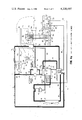
- FIG. 4a is a schematic diagram of the helical screw compressor/expander automotive air conditioning and waste heat energy recovery system employing the unit of FIGS. 1-3 inclusive and forming one embodiment of the present invention, operating under air conditioning mode.
- FIG. 4b is a schematic diagram of the system corresponding to that of FIG. 4a with the system operating under air conditioning mode with pull down.
- FIG. 4c is a schematic diagram corresponding to that of FIG. 4a, with the system operating under heat recovery mode.
- FIG. 4d is the schematic diagram corresponding to that of FIG. 4a, with the system operating under heating mode (above 40° F. ambient).
- FIG. 4e is the schematic diagram corresponding to that of FIG. 4a with the system operating under heating mode (below 40° F. ambient-partial recovery).
- FIGS. 1-3 inclusive show in a preferred form a compact and highly improved compressor/expander of the rotary, helical screw type which is employed in a high speed, variable delivery automotive air conditioning and waste heat energy recovery system as indicated generally at 10, FIGS. 4a-4e for a vehicle comprised of a cab 12.
- the system is highly useful for air conditioning the driver cab for tractor trailer units and the like.
- the system may be employed in a passenger automobile type vehicle.
- the vehicle insofar as vehicle components are concerned, the vehicle, FIG. 4a, includes an engine driven fan 14, normally at the front of the vehicle engine (not shown) and forcing air over various heat exchange coils including the engine radiator (not shown) for cooling of the same.
- the vehicle engine (not shown) includes drive shaft 16, which is coupled to a rotary helical screw compressor/expander unit indicated generally at 18.
- an auxiliary pump 20 may circulate a working fluid within the various conduit means forming the refrigerant connections between certain components of the closed loop refrigeration system.
- the refrigerant is R12.
- Heat exchange coil 22 functions as the system condenser in the loop which further includes a heat exchange coil 24 constituting the primary evaporator and a heat exchange coil 26 forming the system pull down evaporator.
- the vehicle is equipped with an engine exhaust duct or passage means 30 including sections as at 30a, 30b.
- Section 30b houses a vapor boiler 28.
- a cab conditioned air flow duct indicated generally at 32 permits both fresh air and return air to be introduced to the cab interior through conditioned air flow duct section 32c or duct section 32d. Air may be received from the fresh air inlet duct 32a of the duct 32, or cab return air from the cab air return duct 32b which also opens to the interior of cab 12.
- the closed loop refrigeration circuit further comprises as basic elements, a cycle control valve 36, an oil separator 40, a pressure modulator 38, pull down valve 42, and an acceleration unloading valve 44.
- a plurality of heat pipes indicated generally at 31 thermally couple the exhaust duct 30 and the air conditioning duct section 32c for permitting selectively heating of the interior of cab 12 by heat recovery action from the exhaust gas passing through the exhaust duct 30.
- the compressor/expander unit 18 is illustrated schematically as having a capacity slide valve 46 and a volume ratio slide valve 48 or pressure matching slide valve 48', the capacity slide valve 46 being situated at the inlet 50, while the pressure matching or volume ratio slide valve is structurally mounted at outlet 52.
- the compressor is provided with an oil injection port 54 which opens to the compressor interior at a point intermediate of inlet 50 and outlet 52 in terms of the compression or expansion process
- the unit 18 is further provided with a vapor injection port 56 which opens to a compressor closed thread cut off from both the inlet 50 and the outlet 52 and permits refrigerant vapor at intermediate pressure to be returned efficiently to the compressor at a point of the compression or expansion process corresponding to that intermediate pressure.
- the compressor/expander unit 18 is constituted by a three part fixed housing or casing including a central or intermediate casing section 60, a front or driven end casing section 62 and a rear casing section 64, all of which may be formed of cast iron, although alternatively the sections may be formed of aluminum or the like.
- the central section 60 is of irregular configuration and is provided, FIG. 2, with a pair of parallel, longitudinally extending bores as at 66, 68 receiving respectively shafts 70 and 72, bore 66 being counterbored at 66a at one end and 66b at the other, while bore 68 is counterbored at one end 68a and at the other end at 68b.
- the shaft 70 bears the female helical screw rotor as at 74, while shaft 72 bears the male helical screw rotor 76 which is enmeshed therewith within a working chamber as defined by the intermeshed screws and the counterbores 66a and 68a of central or intermediate casing 60.
- the rotor profiles may be circular or assymetrical.
- the male rotor has a diameter, for instance, on the order of 40.8 mm and the female 38.6 mm.
- the L/D ratio (based upon male rotor diameter) is 1.1.
- This type of compressor has very flat performance characteristics (COP, VE, adiabatic efficiency) between speeds of 3,000 to 10,000 rpm, and therefore a speed ratio of 0.1 to turbine speed is preferred.
- the rotors 76 and 74 are supported by bearings as at 75, 78 for shaft 72 and 80 and 82 for shaft 70.
- section 62 of the casing is provided with a bore 84 which receives the bearing 75 and is further provided with an annular recess 86 within one end face 62a thereof, recess 86 receiving bearing 80.
- One end of shaft 70 is borne by the anti-friction bearing 80 in this case.
- Shaft 72 extends completely through the casing section 62.
- the casing section 64 receives a reduced diameter portion 72a of shaft 72 which extends into a bore 88 which extends partially from one end face 64a of casing section 64 and which is further counterbored as at 90 to bear stator 92 and rotor 94 of gear rotor type liquid pump 95.
- the rotor 94 is keyed to reduced diameter shaft portion 72a of shaft 72 by way of key 96.
- the casing section 64 is provided with a projecting portion 64b in the vicinity of the bore 88 and counterbore 90 and is provided with a hole 98 constituting an outlet of the pump as defined by members 92, 94.
- a second hole as at 100 constitutes an inlet for that pump.
- the liquid pump indicated generally at 95, is utilized by the system of FIGS.
- An input ring gear 104 which in the illustrated embodiment of the invention is of approximately 31/2 inch OD, is mounted for rotation on a tubular member 106 by way of bearings 108 and maintained in position by a mounting ring 110 screwed thereto by way of screws 112.
- This gear 104 is splined at 114 to the flange portion 116a of sleeve 116 which, in turn, is splined to the shaft 72 as at 118.
- the tubular mount 106 bears the projecting portion 72b of the shaft 72 beyond bearing 76 and is provided with appropriate seals as at 120.
- Rotation of the male rotor 76 is counterclockwise when viewed from the driven end, via gear 104, FIG. 1.
- the compressor/expander could run in the clockwise direction by providing it as a mirror image to that shown.
- the flange 62a for casing section 62 is provided bolt holes as at 122 to permit the compressor/expander unit to be flange mounted.
- the central casing section 60 is provided with a refrigerant working fluid vapor injection port 124 and an oil injection port 126 which open respectively to bores 66a and 68a housing the female and male helical screw rotors 74, 76, respectively.
- the vapor injection and oil injection ports as at 124, 126 open to the intermeshed screws at positions separate and sealed from the compressor/expander vapor inlet and outlet ports for the same unit.
- the vapor injection port 124 opens to the female rotor bore for pull down capability, that is, accelerated cooling, for instance when the vehicle engine is started after standing in the sun for an extended period of time.
- the oil injection port 126 is employed in returning oil to the male rotor bore 68a. This oil acts to maintain the compressor cool and to seal and lubricate the intermeshed male and female rotors 76, 74.
- the seal mechanism indicated generally at 128 for the male rotor shaft 72 is conventional where it exits the rotor housing as defined by casing section 62 beyond bearing 75. Further, the driving gear 104 is supported by its own bearing system including tubular member 106 and is connected through the splined hub to the male rotor shaft with no clutch mechanism being required due to the fact that the compressor/expander is either being driven or is driving the engine at all times.
- FIG. 3 this cross-sectional view is approximately 90° to that shown in FIG. 2.
- This illustrates completely both slide valves 46 and 48 as well as the inlet and outlet ports, 50a, 52a, and their connection points for the refrigeration loop.
- the intermediate or central compressor casing section 60 is provided with a hole or opening 50 within a flange portion 60a which hole opens up to a cavity 130 and acts as the inlet to the compressor/expander working chamber as defined by bores 66a and 68a.
- FIG. 3 only the male helical screw rotor 76 is shown, the female helical screw rotor overlying the same as seen in FIG. 2 and being in mesh therewith.
- the volume ratio slide valve 48 may be replaced by a pressure matching slide valve of the type shown in U.S. Pat. No. 3,936,239.
- the profile of the slide valves 48 and 46 which are formed of metal blocks machined to the desired configuration is such that surfaces 46a of slide valve 46 and 48a of slide valve 48 act as extensions for the envelope define working chambers as further formed by bores 66a and 68a for the helical screw rotors, as per the reference patent.
- the slide valves 46 and 48 are mounted in respective recesses 132 and 134 formed within the intermediate casing section 60 (and partially within casing section 62 for slide valve 48).
- Slide valve 46 bears piston rod 136, which has fixed thereto at one end, a piston 138 bearing a peripheral seal ring as at 140, piston 138 sliding within a cylindrical bore 142 defining a chamber 143 within casing section 64.
- Casing 64 is provided with a hydraulic fluid inlet port as at 144, permitting the piston and the slide valve 46 to be shifted to the extreme left, FIG. 3, against the bias of a coil spring 146.
- Spring 146 has ends respectively received within a circular recess 148 of the fixed casing section 62 and a similar circular recess 150 within the end face of the slide valve 46.
- the compression spring 146 is such that it normally forces the capacity slide valve 46, absent hydraulic liquid within chamber 144, to its full rightmost or full load position as indicated by dotted line 152a, the capacity slide valve 46 being shown in full lines in part load position.
- the capacity slide valve serves to regulate the inlet flow to the expander, based upon the vapor output of boiler 28, FIG. 4a.
- the dot-dash line 152b represents the position of the capacity slide valve at full load position for expander operation.
- the volume ratio slide valve or v i slide valve 48 is slidably mounted within a recess 134 and bears a piston rod 154 which extends from one end thereof rearwardly.
- the volume ratio slide valve 48 is, in this embodiment, a two position slide valve maintained at either of two extreme positions, depending upon whether the system is in air conditioning or heat recovery mode. Thus, when it is all the way to the left, it is in the "expander" position with a resulting volume ratio or v i of 1.0, while when the volume ratio slide valve 48 is in the position in FIG.
- the capacity slide valve 46 absent hydraulic fluid under pressure within chamber 143 is biased to its extreme full right position by expansion of the coil spring 146.
- the hydraulic fluid for shifting the slide valve 46 by acting on the face of the piston 138 may in fact be the refrigerant working fluid in liquid form, within the closed loop refrigeration system to which the compressor/expander unit has application.
- the volume ratio slide valve 48 is provided without a biasing element such as a coil spring similar to that at 146, in this case absent an applied control pressure fluid such as oil or a working fluid at port 160 and acting on the right side of piston 156, the discharge pressure of the working fluid within outlet passage 162 will act on the left face of piston 156, forcing it to the right.
- the surface area of the piston 156 is larger than the surface area of face 48b of the volume ratio slide valve 48.
- the slide valve 48 will be positioned all of the way to the right in its rightmost position as shown in FIG. 3, for a maximum volume ratio v i as at 3.5.
- the volume ratio slide valve 48 is shifted to its maximum extent determined by the stroke of the piston 156 within cylindrical cavity 150 shifting the end face 48b to the dotted line position 48b', FIG. 3, and providing a volume ratio of 1.0. This allows the refrigerant working fluid or gas to fully expand. There is no recompression.
- FIG. 3a this figure constitutes a modification of the compact, helical screw rotary compressor/expander unit similar to that of FIGS. 1-3 inclusive and employable in the system of FIGS. 4a-4e inclusive.
- Like elements to those found in the embodiment of FIGS. 1-3 inclusive bear like numerical designations. Only portions of casing sections 60 and 62 are shown, and only those relative to the male helical screw rotor 76 and in this case a pressure matching slide valve 48' replacing the volume ratio slide valve 48 of the prior described embodiment, fitting identically within the recess 134 formed within the casing sections 60 and 62.
- An outlet passage 162 is provided leading from the outlet port 52a. End face 48'b defines a portion of the outlet passage 162.
- a piston rod 154' extends from the slide valve 48' and terminates at piston 156' which bears an O-ring seal about its periphery as at 157', bearing on cylindrical cavity 158 defining a chamber 159, within which piston 156' reciprocates.
- the pressure matching slide valve 48' is provided with an inclined small diameter hole or passage 300 opening to the exterior of the slide valve 48' at the surface 48'a defining the envelope apart from the intermeshed helical screw rotor just upstream from the end face 48'b of the slide valve 48' at the discharge side of the compressor/expander unit 18' and defining a closed thread pressure sensing port 302 which opens up to a closed thread and permits sampling of the pressure of the working fluid at the point in the compression or expansion cycle just prior to discharge at port 52a, through the outlet passage 162.
- the slide valve 48' is further axially bored at 304 intersecting the inclined passage 300 and being of a similar, small diameter.
- the shaft 154' is provided with a corresponding small diameter bore 306 which extends to the piston 156' and beyond the shaft 154' terminating within a sleeve 308 having an internal diameter on the order of the external diameter of shaft 154' and forming a slidable, sealed connection therewith, permitting passage 306 to sealably communicate with sleeve 308 regardless of the axially shifted position of piston 156'.
- a line 310 is connected to sleeve 308 and provides a pressure signal to one end of pilot valve 312, the pilot valve 312 housing a pilot valve piston indicated generally at 314 and being comprised of a shaft 316 and four lands as at 318, 320, 322 and 324 sealably contacting at their peripheries the inside of the cylindrical pilot valve casing 326 which is closed off at its ends.
- the pressure matching slide valve, and its operation, is essentially the same as that shown in U.S. Pat. No. 3,936,239 and is briefly referred to herein. Further reference may be had to that patent to fully appreciate and understand the pressure matching function of slide valve 48'.
- a second line 328 extends from a sensing port 330 within casing section 60 at the outlet 52 and fluid communicates the discharge port 52a to the interior of the pilot valve casing 326 on the left side of land 318 of the piston 314.
- a hydraulic fluid inlet line 331 opens to the interior of casing 326 at a central port 332 intermediate of lands 320 and 322.
- the cylinder is provided with a pair of outlet ports as at 334, 336 which connect to an outlet line 340.
- hydraulic fluid is delivered selectively to chamber 159 to one side or the other of piston 156', depending upon whether the pressure matching slide valve 48' is to be driven to the left or the right.
- a line 342 leads from port 344 within casing 326 to port 345 within casing section 62 opening to the chamber 159 on the right side of piston 156', while a line 346 leads from port 348 to a passage 350 within casing section 62 which opens to chamber 159 on the left side of piston 156'. It may be seen that while one side of the piston 156' is receiving hydraulic fluid under pressure, hydraulic fluid previously supplied to the opposite side is draining through the pilot valve back to the return line 340. The source and sump for the hydraulic fluid are not shown. However, schematically, arrows 352 and 354, respectively, represent these elements of the system.
- the slide valve 48' is shifted either to the right or to the left by application and removal of hydraulic fluid under pressure from chamber 159 on respective sides of the piston 156' in accordance with the principles as set forth in U.S. Pat. No. 3,936,239.
- the controlled shifting of the slide valve 48' axially or longitudinally equalizes the pressures to prevent undercompression or overcompression of the working fluid when the unit is in the compression mode, or alternatively, to prevent overexpansion or underexpansion of the working fluid when the unit is functioning as an expander, prior to discharge.
- FIG. 4a because of the explanation of the nature and operation of the compressor/expander unit 18, its capacity slide valve 46 and its volume ratio slide valve 48 (or alternatively its pressure matching slide valve 48') as well as the liquid pump 20, full appreciation of the improved automotive vehicle air conditioning system and waste heat recovery system, in terms of its componentry and the various modes of operation as evidenced by FIGS. 4a-4e inclusive can now be had.
- the outlet 52 of the unit is always connected to the system condenser 22 via oil separator 40 by way of conduit means or line 164 with the separated oil as at O returning to the compressor for injection at oil injection port 54 by way of an oil injection line 166.
- the working fluid R12 passes to condenser 22 via line 168, where the refrigerant working fluid is condensed within the condenser 22 and passes to cycle control valve 36 via line 170.
- the cycle control valve 36 provides for the various modes of operation, depending upon temperature parameters in a manner consistent with conventional refrigeration circuit control. It can be manual or automatic.
- line 172 extends from the cycle control valve 36 to the main evaporator 24 for the system and bears a thermal expansion valve 174 to permit the condensed refrigerant to expand, within line 172 downstream of the expansion valve and to absorb heat by passage through the evaporator 24.
- Line 176 permits the vaporized refrigerant to return to the cycle control valve 36 after picking up thermal energy within the evaporator 24.
- Line 178 leads from the cycle control valve 36 to the inlet 50 to the compressor/expander unit 18 under control of the capacity slide valve 46.
- a line 180 branches from line 174 at point 182 and directs liquid refrigerant to the pull down evaporator coil 26, line 180 including pull down valve 42 constituting a solenoid operated control valve which, when de-energized, blocks flow to the pull down evaporator, but when energized, permits liquid refrigerant to flow to a thermal expansion valve 183 within line 180 downstream of the pull down valve 42, where the refrigerant R12 vaporizes and passes through the pull down evaporator or coil 26 to additionally cool the air passing through duct 32 to the cab 12 in addition to that cooled by the system main evaporator 24.
- a further branch line 184 extends from line 180 at point 186 to the capacity slide valve control inlet port 144, line 184 including an acceleration unloading valve 44 which, like valve 42, constitutes a solenoid operated control valve which, when energized, permits flow through line 184 for the liquid refrigerant from the cycle control valve to the slide valve control inlet port 144 at full compressor discharge pressure, forcing spring 146 to be fully compressed and shifting slide valve 46 to full unload position.
- a bypass line 186 extends about the acceleration unloading valve 44 and bears a pressure modulator 38 which can modulate the pressure of the liquid refrigerant within the bypass line 186 and passing to the slide valve control inlet 144 as control pressure liquid when the acceleration unloading valve 44 is de-energized and closed.
- a line 190 extends from the pressure modulator 38 to line 176 downstream of the evaporator.
- the pressure of the liquid refrigerant available to the slide valve control inlet port 144 as a control signal is dependent upon the pressure within the line 176 returning to the suction side of the compressor from the evaporator coil 24, and thus compressor or expander capacity is modulated by evaporator coil 24 vapor return pressure, absent energization of acceleration unloading valve 44.
- the pull down evaporator coil 26 does not return to the suction or inlet port 50 for the compressor/expander unit 18, but rather returns to a vapor injection port 56 via vapor injection line 192 at a closed thread position which is intermediate of the suction and discharge pressures for the compressor.
- the cycle control valve 36 further includes line 194 which extends from that valve to inlet 100 of liquid pump 70 and line 196 which connects the outlet 98 of that pump to vapor boiler 28, permitting liquid refrigerant to pass to the vapor boiler 28 for vaporization as a result of heat exchange with the exhaust gases from the vehicle internal combustion engine.
- the vaporized refrigerant returns to the cycle control valve via line 198.
- Indirect heat transfer is effected from the exhaust gas to the air to be conditioned flowing to cab 12 within duct 32.
- the plurality of heat pipes 34 have opposed ends in heat transfer position with respect to the exhaust duct 30 and section 32c of the conditioned air flow duct 32.
- a cab air return duct 32b connects to the cab interior at 200 and merges with fresh air duct portion or section 32a at point 202, the cab air return duct 32b preferably including a blower as indicated schematically by fan blade 204 for forcing air circulation through the duct 32 to and from the cab interior 12 as well as permitting fresh air to enter through fresh air inlet opening 206 within the fresh air duct 32a, the cab 12 may be conditioned purely by way of recirculation of cab air or by way of fresh air selectively, this being achieved by the utilization of a pivotable fresh air damper 208 mounted within duct section 32a and closing off the opening 206 when in vertical position, but pivotable about the axis of pivot pin 210 mounted to the duct and supporting the damper 208 to a horizontal position or an inclined intermediate position to selectively vary the amount of fresh air entering the cab interior 12.
- a motor 209 is provided to rotate damper 208.
- duct 32 Downstream of the pull down evaporator coil 26 and the main evaporator coil 24, duct 32 splits into the two sections 32c and 32d as mentioned previously.
- a heat pipe bypass damper At the upstream end of duct section 32c, there is provided a heat pipe bypass damper at 212 which pivots about a pivot pin 214, driven by motor 211, between the vertical position shown in FIG. 4a which closes off duct section 32c to air flow downstream of the two coils 26 and 24.
- the air bypasses the duct section 32c, passing through duct section 32d and entering the cab interior through an opening 216.
- the damper 212 when the damper 212 is in a horizontal position, it closes off the upstream end of duct section 32d and forces the air flow to pass through duct section 32c and enter the cab interior through opening 218.
- ends 34a of the heat pipes 34 which may be enlarged in diameter and finned to insure excellent heat exchange between the air flowing across ends 34a of these elements.
- the opposite ends 34b of the heat pipes 34 are disposed within the exhaust duct section 30a, that section being separated by means of a longitudinally extending wall 220 so as to define a lower heat pipe bypass flow path or passage as at 222 and an upper flow path or passage as at 224.
- the flow paths are controlled by a heater bypass damper 226 being pivoted at one end for rotation about the axis of pivot pin 228 mounted to the duct 30, the damper 226 being driven by a motor 227 and pivoting 180° so as to close off selectively either passage 222 or 224.
- the lower ends 34b of the heat pipes 34 are disposed within passage 224 so that when the exhaust gas passes through the passage 224 on the upper side of the wall 220, the heat of the exhaust gas is transferred by way of the heat pipes 34 to ends 340a within duct section 32c.
- the duct section 30b is enlarged downstream from the heat pipes 34 and provided with a longitudinally extending generally horizontal separating wall 230 defining an upper vapor boiler bypass flow path or passage 232 at this point and a lower flow path or passage 234 prior to discharge at the discharge opening 236 for the exhaust duct 30.
- the vapor boiler 28 is disposed within the flow path 234 and the wall 230 is extended at its upstream end transversely to the direction of flow of the exhaust gases, and includes an upstream opening 238 which may be selectively cut off by a further vapor boiler bypass damper 240, which is pivoted at one end by way of pivot pin 242 and driven by motor 241, so that when it is disposed horizontally and spans opening 238, it forces the exhaust gas to flow into the upper flow path 232 bypassing the vapor boiler, while when it is deflected to a horizontal position at 90° thereto, this damper closes off the upper vapor boiler bypass flow path 232 and forces the exhaust gas to pass through the lower flow path 234 and effectively heat and vaporize the refrigerant within the vapor boiler 28 causing an increase in its enthalpy.
- a further vapor boiler bypass damper 240 which is pivoted at one end by way of pivot pin 242 and driven by motor 241, so that when it is disposed horizontally and spans opening 238, it forces the exhaust
- the cycle control valve 36 is preferably temperature controlled by thermosensors (not shown). Further, cycle control valve 36 controls the feed of liquid refrigerant at compressor discharge pressure through line 195 to control port 160 for chamber 159 to force slide valve 48 to minimum volume ratio position. In addition, several of the dampers are automatically shifted between extreme positions depending upon the temperature of the air flow passing through portions of the ducts 30 and 32. Each damper is equipped with a thermal responsive drive motor. In that respect, the damper 212 is controlled directly by a thermal sensor as at 244 mounted within duct section 32c downstream of the heat pipes 34 and controlling the position of damper 212 upstream thereof by effecting a shift between vertical and horizontal positions for damper 212 via control line 246 to motor 211.
- the damper 240 is shifted between vertical and horizontal positions depending upon the temperature of the vaporized refrigerant passing through the vapor boiler 28 as determined by thermosensor 248 within that line and downstream of the vapor boiler, the thermosensor 248 being connected to a drive motor 241 associated with the damper 240 for pivoting the damper 240 about the axis of its pivot pin 242 by line 250.
- FIG. 4a shows the dual air conditioning and waste heat recovery system under an air conditioning mode for the cab interior 12.
- the exhaust duct damper 226 is in the vertically up position, forcing air flow through heat pipe bypass passage or path 222 within section 30a of the exhaust duct 30, while the damper 240 is maintained in its vertical position closing off air flow to passage 234 housing the vapor boiler 28.
- the exhaust gas simply passes to the discharge opening 236 of the manifold without any effective thermal exchange with heat pipes 34 or vapor boiler 28.
- the compressor/expander unit 18 is functioning to compress the refrigerant which is returned from the main evaporator coil 24 by means of the cycle control valve 36 via lines 176 and 178 to the unit inlet 50 under control of the capacity slide valve 46.
- Capacity of the compressor is determined by the pressure within the return vapor line 176 by way of modulation control line 190 which opens to the pressure modulator 38.
- the acceleration unloading valve 44 is de-energized.
- the compressor/expander unit in compressor mode has its capacity matching the load as defined by the heat pick up by the evaporator coil 24.
- the pull down valve 42 is de-energized.
- the compressor is operating and the cycle control valve operates to direct compressed refrigerant vapor, after oil separation, to the condenser 22, where the liquid refrigerant passes to the evaporator coil via line 172 under control of the thermal expansion valve 174.
- the fresh air damper 208 is closed, and the fan 204 is energized to force the cab air to circulate from the cab outlet opening 200 through the cab air return duct section 32b, the main portion of conditioned air flow duct 32 housing the main evaporator coil 24 and returning air to the cab interior by way of duct section 32d with the heat pipe damper 212 in the vertical position closing off the upstream end of duct section 32c housing the heat pipes 34.
- FIG. 4b the system is shown in an air conditioning mode with the pull down evaporator coil provided with refrigerant for additionally picking up heat within the air being recirculated through the duct 32 to and from the cab interior 12.
- the cycle control valve remains the same as in FIG. 4a.
- the pull down valve 42 is energized such that a portion of the liquid refrigerant passes through line 180 to the pull down evaporator coil 26.
- the thermal expansion valve 182 causes the liquid refrigerant to expand.
- the refrigerant vapor within the pull down evaporator 26 expands to a pressure intermediate of the pressure of the refrigerant vapor at inlet 50, and discharge at outlet 52, returning to the compressor by way of the vapor injection port 56 via line 192.
- the acceleration unloading valve 44 is closed, and the capacity slide valve is positioned in accordance with load conditions as sensed by the refrigerant vapor discharging from the evaporator 24 through the pressure modulator modulation control line 190 which controls the pressure of the liquid refrigerant as the piston power fluid entering chamber 143 to the right of piston 138 by way of slide valve control fluid inlet port 144.
- the system is functioning to provide cooling for the cab interior 12.
- the volume ratio slide valve 48 is maintained at its rightmost position, FIG. 3, without application of any pressure fluid on the right side of piston 156.
- the end wall 48b on the right of the volume ratio slide valve 48 is subjected to compressor discharge pressure as well as the larger surface area as provided by the left side of piston 156 such that the slide valve is maintained in the rightmost "compressor" position.
- the built in compression ratio or v i of 3.5 is therefore provided when operating in the compressor (refrigeration cooling) mode.
- FIG. 4c the system is illustrated in a heat recovery mode where there is no necessity to provide either cooling or heating to the air within the cab or vehicle interior 12.
- the compressor/expander unit 18 is now functioning as an expander.
- the energy for the system comes from the exhaust gas which is prevented from providing effective heat exchange with the heat pipes 34, since the heater bypass damper 226 is maintained in its vertical, upright position relative to the axis of its pivot pin 228, the exhaust gas passing through bypass passage 222 of section 30a of the exhaust manifold.
- the vapor boiler 28 provides the necessary heat exchange for the refrigerant working fluid which is forced under pressure to the vapor boiler through line 196 from the outlet 98 of the liquid pump.
- the expanded vapor discharges by way of outlet port 52a under control of the volume ratio slide valve 48 and passes by way of lines 164 and 168 to the condenser 22, where the refrigerant is liquified. It returns to the inlet port 100 of the liquid pump by way of the cycle control valve 36 through lines 170 and 194.
- FIG. 4d the automotive vehicle air conditioning and waste heat recovery system is shown in operation under a heating mode which is arbitrarily set above 40° F. ambient in terms of operation of the cycle control valve 36.
- the heater bypass damper 226 is shifted by the heater bypass control motor 227 from a vertical upright position to a horizontal position closing off the upstream end of passage 222 of the heater bypass passage 222 and forcing the exhaust gas to pass over the lower ends 34b of heat pipes 34 to cause vaporization of the confined working fluid within the individual heat pipes and migration by gas to the opposite ends 34a located within the conditioned air flow duct section 32c.
- the resulting temperature within the duct section 32c downstream of the heat pipe results in the thermal sensor 244 actuating automatically the heater bypass damper drive motor 211 to cause the damper 212 to move from a vertical position to a horizontal position, opening the upper end of the duct section 32c and closing off the bypass duct section 32d.
- the vapor boiler bypass damper 240 is closed by operation of the drive motor 241 under control of thermostat 248 which senses the drop in temperature of the vapor in line 198 since the cycle control valve 36 no longer effects the circulation of working fluid in liquid form through the liquid pump 20 and line 196 to the vapor boiler 28. Closing off the passage 234 results in a flow of the exhaust gas through the vapor boiler bypass passage 232 for discharge from the exhaust manifold or duct 30 at the discharge opening 236.
- the refrigeration loop as evidenced by evaporator 24 and condenser 22 functions to provide limited cooling at the evaporator 24 to reduce the humidity of the air passing over the ends 34a of the heat pipes prior to entering the cab interior as at 12.
- the fresh air damper 208 is driven by motor 209 to an open or partially open position to merge some fresh air with the cab recirculation air by way of cab air return duct 32b, the air mixture passing through the duct 32 and contacting the coil of evaporator 24.
- the compressor/expander unit 18 is functioning as a compressor.
- the position of the capacity control slide valve 46 is dictated by the vapor pressure of the refrigerant leaving the evaporator 24 as provided by the control through the line 190 to the pressure modulator 38 which modulates the pressure of the liquid refrigerant available to the slide valve chamber 143 behind piston 138 and acting to shift slide valve 46 to the left against the bias of the compression coil spring 146.
- the pull down valve 42 is de-energized, the pull down evaporator 26 is not employed, and the refrigerant vapor passing from the evaporator coil 24 through line 176 returns to the inlet port 50 for the compressor/expander unit 18 via line 178.
- the refrigerant vapor is discharged through outlet 52 and passes via lines 164 and 168 to the condenser with oil separation occurring at oil separator 40.
- the condensed refrigerant passes by way of line 170 back to the control cycle valve 36, where it is directed by line 172 back to the evaporator with expansion of the refrigerant occurring at the thermal expansion valve 174 upstream of the evaporator 24. Oil injection occurs. However, there is no vapor injection as the pull down evaporator coil is not functioning.
- FIG. 4e the system is shown in a heating mode.
- the ambient temperature is below 40° F.
- the system operates under partial recovery, that is, the heat which is not extracted by the heat pipes 34 from the exhaust gas passing through the exhaust duct 30 is employed by the vapor boiler 28 to vaporize refrigerant working fluid which passes to the compressor/expander unit 18, where it is expanded, providing useful work, not only for driving the liquid pump 20 but also tending to return mechanical energy to the vehicle engine drive shaft through gear 104.
- the volume ratio slide valve 48 is shifted by liquid refrigerant under pressure, via cycle control valve 36 and line 195 to the slide valve control port 160 driving piston 156 to the left and changing the unit volume ratio from 3.5 to 1.0 which maximizes the expansion of the refrigerant available to the inlet 50 under proper positioning of the capacity control valve without recompression prior to expansion.
- the unit improves compressor/expander efficiency by the incorporation of the slide valves 46 and 48 and the control of the same.
- the vaporized refrigerant working fluid which returns to the unit 18 functioning as an expander by way of line 198 under control of the cycle control valve 36 expands within the unit 18, discharges at outlet 52 and passes through the oil separator 40 to the condenser 22 via lines 164 and 168.
- the liquid refrigerant returns to the cycle control valve 36 through line 170 and is pumped by operation of the liquid pump 20 through lines 194 and 196 back to the vapor boiler for revaporization, providing effective motive force derived from the waste heat normally discharged through the outlet 236 of the exhaust duct or pipe 30.
- the v i slide valve 48 may be replaced as in FIG. 3a, by the pressure matching slide valve 48'.
- Port 302 which opens to a closed thread just upstream of the discharge, as defined by the end face 48'b of the slide valve 48', feeds to pressure comparator or pilot valve 312, the comparator 312 providing a drive signal to chamber 159 to vary the axial position of piston 156' and thus slide valve 48' to match closed thread pressure at discharge to condenser 22 pressure.
- inlet port 50a functions to supply working fluid in vapor form to the unit 18, whether it functions as an expander or a compressor. Therefore, the helical screw rotors 74 and 76 always turn in the same direction and the rotors being gear coupled to the prime mover, whether a gasoline or diesel internal combustion engine, as in the instant environment, or an electric motor or gas turbine engine when more broadly applied to a prime mover system in which it is desirable to drive the unit as a compressor from the prime mover or to supply power input to the mechanical drive system by waste heat recovery when the unit is being utilized as an expander.
- the capacity slide valve 46 When operating as a compressor, absent hydraulic fluid under pressure at control port 144 and chamber 143 on the right side of piston 138, the capacity slide valve 46 may move all the way to the right, as evidenced by dash-dot line 152a to expose the complete inner lobe volume to suction, the capacity slide being under full load position for the compressor operation.
- acceleration unloading valve 44 To fully unload the unit acting as a compressor, energization of the acceleration unloading valve 44 occurs so that liquid refrigerant at full discharge pressure is directed to control port 144, shifting the slide valve to the position shown in FIG. 3, fully compressing coil spring 146 to its leftmost position as defined by piston contact with the right hand edge of casing section 60, FIG. 3, within cylindrical cavity 142.
- the capacity slide valve 46 is shifted to the position indicated with end face 152 at dash-dot line 152b. This is the position which is full load position when the unit is functioning as an expander.
- the volume ratio slide valve 48 is shifted to its full left position, providing a minimum volume ratio in order to gain maximum expansion of the vapor from the boiler prior to discharge through outlet 52. If the volume ratio slide valve 48 is maintained in the position shown in FIG. 3, when the unit 18 functions as an expander, there will be developed a very high inner lobe pressure. The vapor cannot totally expand, and as such, by shifting the v i slide valve 48 to its extreme left position, FIG. 3, this vapor is allowed to fully expand without any recompression. Thus, the unit operates as a unidirectional flow device, regardless of whether it is functioning as an expander or compressor.
- the rotor profiles may be either circular or assymetrical. It should be appreciated that in small assymetrical compressor/expander units, there are distinct seal problems and leakage problems at the intermesh between the rotors, and while units with assymetrical profiles have small leakage problems when operating as a compressor, such leakage is a major problem when the unit operates as an expander. To the contrary, with a circular profile, the leakage problem when operating as a compressor is moderate and when operating as an expander is minimized.
Abstract
Description
Claims (23)
Priority Applications (1)
| Application Number | Priority Date | Filing Date | Title |
|---|---|---|---|
| US06/000,601 US4220197A (en) | 1979-01-02 | 1979-01-02 | High speed variable delivery helical screw compressor/expander automotive air conditioning and waste heat energy _recovery system |
Applications Claiming Priority (1)
| Application Number | Priority Date | Filing Date | Title |
|---|---|---|---|
| US06/000,601 US4220197A (en) | 1979-01-02 | 1979-01-02 | High speed variable delivery helical screw compressor/expander automotive air conditioning and waste heat energy _recovery system |
Publications (1)
| Publication Number | Publication Date |
|---|---|
| US4220197A true US4220197A (en) | 1980-09-02 |
Family
ID=21692210
Family Applications (1)
| Application Number | Title | Priority Date | Filing Date |
|---|---|---|---|
| US06/000,601 Expired - Lifetime US4220197A (en) | 1979-01-02 | 1979-01-02 | High speed variable delivery helical screw compressor/expander automotive air conditioning and waste heat energy _recovery system |
Country Status (1)
| Country | Link |
|---|---|
| US (1) | US4220197A (en) |
Cited By (30)
| Publication number | Priority date | Publication date | Assignee | Title |
|---|---|---|---|---|
| US5121607A (en) * | 1991-04-09 | 1992-06-16 | George Jr Leslie C | Energy recovery system for large motor vehicles |
| WO1992016389A1 (en) * | 1991-03-19 | 1992-10-01 | Behr Gmbh & Co. | Process for cooling drive components and heating the passenger compartment of a motor vehicle, especially an electrically driven vehicle, and arrangement for implementing the process |
| EP0523550A1 (en) * | 1991-07-10 | 1993-01-20 | Ebara Corporation | Screw vacuum pump |
| EP0523551A1 (en) * | 1991-07-10 | 1993-01-20 | Ebara Corporation | Screw vacuum pump |
| US5722254A (en) * | 1996-06-05 | 1998-03-03 | Delau Innovations, Ltd. | Refrigerated serving device |
| KR20000030467A (en) * | 2000-02-26 | 2000-06-05 | 김원봉 | Hydraulic engine |
| US6394777B2 (en) | 2000-01-07 | 2002-05-28 | The Nash Engineering Company | Cooling gas in a rotary screw type pump |
| US20040040332A1 (en) * | 2002-09-03 | 2004-03-04 | Bitzer Kuehlmaschinenbau Gmbh | Screw compressor |
| US20050226758A1 (en) * | 2002-12-03 | 2005-10-13 | Bitzer Kuehlmaschinenbau Gmbh | Screw compressor |
| US20050229629A1 (en) * | 2002-12-16 | 2005-10-20 | Behr Gmbh & Co. Kg | Refrigerant circuit and a refrigerating system |
| US20070095083A1 (en) * | 2005-10-28 | 2007-05-03 | Lg Electronics Inc. | Method and apparatus for removing partial overload in an air conditioner |
| US20080141664A1 (en) * | 2006-12-18 | 2008-06-19 | David Bidner | Engine System Including Heat Pipe |
| US20090028723A1 (en) * | 2007-07-23 | 2009-01-29 | Wallis Frank S | Capacity modulation system for compressor and method |
| US20100196836A1 (en) * | 2009-02-03 | 2010-08-05 | Craig Moller | Sealing Mechanism for a Vacuum Heat Treating Furnace |
| CN102748285A (en) * | 2012-04-11 | 2012-10-24 | 无锡市制冷设备厂有限责任公司 | Screw compressor |
| US8308455B2 (en) | 2009-01-27 | 2012-11-13 | Emerson Climate Technologies, Inc. | Unloader system and method for a compressor |
| USRE44636E1 (en) | 1997-09-29 | 2013-12-10 | Emerson Climate Technologies, Inc. | Compressor capacity modulation |
| US20140041482A1 (en) * | 2012-08-09 | 2014-02-13 | GM Global Technology Operations LLC | Electro-mechanical drive-unit |
| CN104141607A (en) * | 2014-07-25 | 2014-11-12 | 温岭市鑫磊空压机有限公司 | Screw compressor easy to assemble |
| US20150330703A1 (en) * | 2012-12-28 | 2015-11-19 | Daikin Industries, Ltd. | Refrigeration device |
| CN106801619A (en) * | 2017-03-03 | 2017-06-06 | 上海维尔泰克螺杆机械有限公司 | The adjustable screw expander of volumetric ratio |
| US10174641B2 (en) | 2014-10-10 | 2019-01-08 | Hyundai Motor Company | Rankine cycle system for vehicle having dual fluid circulation circuit and method of controlling the same |
| US10208754B2 (en) | 2015-10-08 | 2019-02-19 | Ingersoll-Rand Company | Oil flooded compressor system and method |
| US10240602B2 (en) | 2016-07-15 | 2019-03-26 | Ingersoll-Rand Company | Compressor system and method for conditioning inlet air |
| US10378533B2 (en) | 2011-12-06 | 2019-08-13 | Bitzer Us, Inc. | Control for compressor unloading system |
| US10428713B2 (en) | 2017-09-07 | 2019-10-01 | Denso International America, Inc. | Systems and methods for exhaust heat recovery and heat storage |
| CN111397286A (en) * | 2020-03-02 | 2020-07-10 | 北京空间机电研究所 | Aerospace remote sensor refrigerator heat dissipation device based on loop heat pipe |
| US10724524B2 (en) | 2016-07-15 | 2020-07-28 | Ingersoll-Rand Industrial U.S., Inc | Compressor system and lubricant control valve to regulate temperature of a lubricant |
| US10876768B2 (en) | 2018-09-21 | 2020-12-29 | Denso International America, Inc. | Screw compressor for HVAC |
| US20230027313A1 (en) * | 2021-07-21 | 2023-01-26 | Vilter Manufacturing Llc | Self-Positioning Volume Slide Valve for Screw Compressor |
Citations (2)
| Publication number | Priority date | Publication date | Assignee | Title |
|---|---|---|---|---|
| US2869332A (en) * | 1954-09-13 | 1959-01-20 | Robert T Collier | Refrigerator drive utilizing waste heat |
| US3936239A (en) * | 1974-07-26 | 1976-02-03 | Dunham-Bush, Inc. | Undercompression and overcompression free helical screw rotary compressor |
-
1979
- 1979-01-02 US US06/000,601 patent/US4220197A/en not_active Expired - Lifetime
Patent Citations (2)
| Publication number | Priority date | Publication date | Assignee | Title |
|---|---|---|---|---|
| US2869332A (en) * | 1954-09-13 | 1959-01-20 | Robert T Collier | Refrigerator drive utilizing waste heat |
| US3936239A (en) * | 1974-07-26 | 1976-02-03 | Dunham-Bush, Inc. | Undercompression and overcompression free helical screw rotary compressor |
Cited By (46)
| Publication number | Priority date | Publication date | Assignee | Title |
|---|---|---|---|---|
| WO1992016389A1 (en) * | 1991-03-19 | 1992-10-01 | Behr Gmbh & Co. | Process for cooling drive components and heating the passenger compartment of a motor vehicle, especially an electrically driven vehicle, and arrangement for implementing the process |
| US5725048A (en) * | 1991-03-19 | 1998-03-10 | Behr Gmbh & Co. | Process for cooling drive components and heating the passenger compartment of a motor vehicle, especially an electrically driven vehicle, and arrangement for implementing the process |
| US5121607A (en) * | 1991-04-09 | 1992-06-16 | George Jr Leslie C | Energy recovery system for large motor vehicles |
| EP0523550A1 (en) * | 1991-07-10 | 1993-01-20 | Ebara Corporation | Screw vacuum pump |
| EP0523551A1 (en) * | 1991-07-10 | 1993-01-20 | Ebara Corporation | Screw vacuum pump |
| US5314320A (en) * | 1991-07-10 | 1994-05-24 | Ebara Corporation | Screw vacuum pump with a reduced starting load |
| US5374170A (en) * | 1991-07-10 | 1994-12-20 | Ebara Corporation | Screw vacuum pump |
| US5722254A (en) * | 1996-06-05 | 1998-03-03 | Delau Innovations, Ltd. | Refrigerated serving device |
| US6293124B1 (en) | 1996-06-05 | 2001-09-25 | Delau Innovations, Ltd. | Refrigerated apparatus |
| USRE44636E1 (en) | 1997-09-29 | 2013-12-10 | Emerson Climate Technologies, Inc. | Compressor capacity modulation |
| US6394777B2 (en) | 2000-01-07 | 2002-05-28 | The Nash Engineering Company | Cooling gas in a rotary screw type pump |
| KR20000030467A (en) * | 2000-02-26 | 2000-06-05 | 김원봉 | Hydraulic engine |
| US6898948B2 (en) * | 2002-09-03 | 2005-05-31 | Bitzer Kuehlmaschinenbau Gmbh | Screw compressor |
| CN1312402C (en) * | 2002-09-03 | 2007-04-25 | 比泽尔制冷设备有限公司 | Screw compressor |
| US20040040332A1 (en) * | 2002-09-03 | 2004-03-04 | Bitzer Kuehlmaschinenbau Gmbh | Screw compressor |
| US20050226758A1 (en) * | 2002-12-03 | 2005-10-13 | Bitzer Kuehlmaschinenbau Gmbh | Screw compressor |
| US7201569B2 (en) * | 2002-12-03 | 2007-04-10 | Bitzer Kuehlmaschinenbau Gmbh | Screw compressor |
| US20050229629A1 (en) * | 2002-12-16 | 2005-10-20 | Behr Gmbh & Co. Kg | Refrigerant circuit and a refrigerating system |
| US20070095083A1 (en) * | 2005-10-28 | 2007-05-03 | Lg Electronics Inc. | Method and apparatus for removing partial overload in an air conditioner |
| US7832204B2 (en) | 2006-12-18 | 2010-11-16 | Ford Global Technologies, Llc | Engine system including heat pipe |
| US20080141664A1 (en) * | 2006-12-18 | 2008-06-19 | David Bidner | Engine System Including Heat Pipe |
| US20090028723A1 (en) * | 2007-07-23 | 2009-01-29 | Wallis Frank S | Capacity modulation system for compressor and method |
| US8157538B2 (en) | 2007-07-23 | 2012-04-17 | Emerson Climate Technologies, Inc. | Capacity modulation system for compressor and method |
| US8807961B2 (en) | 2007-07-23 | 2014-08-19 | Emerson Climate Technologies, Inc. | Capacity modulation system for compressor and method |
| US8308455B2 (en) | 2009-01-27 | 2012-11-13 | Emerson Climate Technologies, Inc. | Unloader system and method for a compressor |
| US20100196836A1 (en) * | 2009-02-03 | 2010-08-05 | Craig Moller | Sealing Mechanism for a Vacuum Heat Treating Furnace |
| JP2010181135A (en) * | 2009-02-03 | 2010-08-19 | Ipsen Inc | Sealing mechanism for vacuum heat treating furnace |
| US8992213B2 (en) * | 2009-02-03 | 2015-03-31 | Ipsen, Inc. | Sealing mechanism for a vacuum heat treating furnace |
| US10378533B2 (en) | 2011-12-06 | 2019-08-13 | Bitzer Us, Inc. | Control for compressor unloading system |
| CN102748285A (en) * | 2012-04-11 | 2012-10-24 | 无锡市制冷设备厂有限责任公司 | Screw compressor |
| US20140041482A1 (en) * | 2012-08-09 | 2014-02-13 | GM Global Technology Operations LLC | Electro-mechanical drive-unit |
| US8783135B2 (en) * | 2012-08-09 | 2014-07-22 | GM Global Technology Operations LLC | Electro-mechanical drive-unit |
| US20150330703A1 (en) * | 2012-12-28 | 2015-11-19 | Daikin Industries, Ltd. | Refrigeration device |
| US9829242B2 (en) * | 2012-12-28 | 2017-11-28 | Daikin Industries, Ltd. | Refrigeration device |
| CN104141607A (en) * | 2014-07-25 | 2014-11-12 | 温岭市鑫磊空压机有限公司 | Screw compressor easy to assemble |
| US10287927B2 (en) | 2014-10-10 | 2019-05-14 | Hyundai Motor Company | Rankine cycle system for vehicle having dual fluid circulation circuit and method of controlling the same |
| US10174641B2 (en) | 2014-10-10 | 2019-01-08 | Hyundai Motor Company | Rankine cycle system for vehicle having dual fluid circulation circuit and method of controlling the same |
| US10208754B2 (en) | 2015-10-08 | 2019-02-19 | Ingersoll-Rand Company | Oil flooded compressor system and method |
| US10711785B2 (en) | 2015-10-08 | 2020-07-14 | Ingersoll-Rand Industrial U.S., Inc. | Oil flooded compressor system and method |
| US10240602B2 (en) | 2016-07-15 | 2019-03-26 | Ingersoll-Rand Company | Compressor system and method for conditioning inlet air |
| US10724524B2 (en) | 2016-07-15 | 2020-07-28 | Ingersoll-Rand Industrial U.S., Inc | Compressor system and lubricant control valve to regulate temperature of a lubricant |
| CN106801619A (en) * | 2017-03-03 | 2017-06-06 | 上海维尔泰克螺杆机械有限公司 | The adjustable screw expander of volumetric ratio |
| US10428713B2 (en) | 2017-09-07 | 2019-10-01 | Denso International America, Inc. | Systems and methods for exhaust heat recovery and heat storage |
| US10876768B2 (en) | 2018-09-21 | 2020-12-29 | Denso International America, Inc. | Screw compressor for HVAC |
| CN111397286A (en) * | 2020-03-02 | 2020-07-10 | 北京空间机电研究所 | Aerospace remote sensor refrigerator heat dissipation device based on loop heat pipe |
| US20230027313A1 (en) * | 2021-07-21 | 2023-01-26 | Vilter Manufacturing Llc | Self-Positioning Volume Slide Valve for Screw Compressor |
Similar Documents
| Publication | Publication Date | Title |
|---|---|---|
| US4220197A (en) | High speed variable delivery helical screw compressor/expander automotive air conditioning and waste heat energy _recovery system | |
| US4058988A (en) | Heat pump system with high efficiency reversible helical screw rotary compressor | |
| CA2792543C (en) | Waste heat utilization system for internal combustion engine, and motor-generator device for use in the system | |
| US7260952B2 (en) | Fluid machine | |
| US7080520B2 (en) | Air conditioning system | |
| US7249459B2 (en) | Fluid machine for converting heat energy into mechanical rotational force | |
| US6935126B2 (en) | Refrigeration cycle system | |
| US4487029A (en) | Variable-displacement rotary fluid compressor and air conditioning system using the compressor | |
| US5241817A (en) | Screw engine with regenerative braking | |
| JPS6119443B2 (en) | ||
| GB2112916A (en) | Oil cooling apparatus for refrigeration screw compressor | |
| JPH02118362A (en) | Capacity control air conditioner | |
| US20060179843A1 (en) | Fluid machine | |
| US6263687B1 (en) | Air conditioning systems | |
| US6655164B2 (en) | Combined heating and cooling system | |
| US4312188A (en) | Heat pump system | |
| JP4079114B2 (en) | Fluid machinery | |
| JP4078994B2 (en) | Fluid machinery and waste heat recovery system | |
| US5966952A (en) | Heat pump system with balanced total heating-emitting and absorbing capacities and method for stable heat pumping operation | |
| JP3491323B2 (en) | Air conditioner | |
| JPS62280549A (en) | Refrigerator adjusting capacity | |
| JPS6229779A (en) | Compressor for vehicle air conditioner | |
| JP4711884B2 (en) | Rotation output generator | |
| JP3617742B2 (en) | Scroll compressor and air conditioner | |
| JP3187587B2 (en) | Vehicle air conditioner |
Legal Events
| Date | Code | Title | Description |
|---|---|---|---|
| AS | Assignment |
Owner name: BT COMMERCIAL CORPORATION Free format text: SECURITY INTEREST;ASSIGNOR:DUNHAM-BUSH, INC. A CORP. OF DE.;REEL/FRAME:004546/0912 Effective date: 19851212 |
|
| AS | Assignment |
Owner name: CONNECTICUT BANK AND TRUST COMPANY, N.A., THE, A Free format text: SECURITY INTEREST;ASSIGNOR:DUNHAM BUSH INC.;REEL/FRAME:005197/0373 Effective date: 19891130 |
|
| AS | Assignment |
Owner name: MARSHALL INDUSTRIES, INC. Free format text: CHANGE OF NAME;ASSIGNOR:DUNHAM-BUSH, INC.;REEL/FRAME:005270/0026 Effective date: 19890414 |
|
| AS | Assignment |
Owner name: DUNHAM-BUSH, INC., CONNECTICUT Free format text: RELEASE AND REASSIGNMENT;ASSIGNOR:BT COMMERCIAL CORPORATION;REEL/FRAME:007205/0433 Effective date: 19891129 |
|
| AS | Assignment |
Owner name: FLEET BANK, NATIONAL ASSOCIATION, CONNECTICUT Free format text: SECURITY INTEREST;ASSIGNOR:FEDERAL DEPOSIT INSURANCE CORPORATION, RECEIVER FOR THE NEW CONNECTICUT BANK AND TRUST, N.A.;REEL/FRAME:007317/0060 Effective date: 19941208 Owner name: DUNHAM-BUSH, INC., CONNECTICUT Free format text: RELEASE BY SECURED PARTY;ASSIGNOR:FLEET BANK, NATIONAL ASSOCTAION;REEL/FRAME:007319/0265 Effective date: 19941229 |