US4259705A - Combination surge suppressor filter - Google Patents
Combination surge suppressor filter Download PDFInfo
- Publication number
- US4259705A US4259705A US06/024,379 US2437979A US4259705A US 4259705 A US4259705 A US 4259705A US 2437979 A US2437979 A US 2437979A US 4259705 A US4259705 A US 4259705A
- Authority
- US
- United States
- Prior art keywords
- electrical
- socket
- conductors
- suppressor
- filter
- Prior art date
- Legal status (The legal status is an assumption and is not a legal conclusion. Google has not performed a legal analysis and makes no representation as to the accuracy of the status listed.)
- Expired - Lifetime
Links
Images


Classifications
-
- H—ELECTRICITY
- H02—GENERATION; CONVERSION OR DISTRIBUTION OF ELECTRIC POWER
- H02H—EMERGENCY PROTECTIVE CIRCUIT ARRANGEMENTS
- H02H9/00—Emergency protective circuit arrangements for limiting excess current or voltage without disconnection
- H02H9/005—Emergency protective circuit arrangements for limiting excess current or voltage without disconnection avoiding undesired transient conditions
-
- H—ELECTRICITY
- H01—ELECTRIC ELEMENTS
- H01R—ELECTRICALLY-CONDUCTIVE CONNECTIONS; STRUCTURAL ASSOCIATIONS OF A PLURALITY OF MUTUALLY-INSULATED ELECTRICAL CONNECTING ELEMENTS; COUPLING DEVICES; CURRENT COLLECTORS
- H01R13/00—Details of coupling devices of the kinds covered by groups H01R12/70 or H01R24/00 - H01R33/00
- H01R13/66—Structural association with built-in electrical component
- H01R13/665—Structural association with built-in electrical component with built-in electronic circuit
- H01R13/6666—Structural association with built-in electrical component with built-in electronic circuit with built-in overvoltage protection
-
- H—ELECTRICITY
- H02—GENERATION; CONVERSION OR DISTRIBUTION OF ELECTRIC POWER
- H02H—EMERGENCY PROTECTIVE CIRCUIT ARRANGEMENTS
- H02H9/00—Emergency protective circuit arrangements for limiting excess current or voltage without disconnection
- H02H9/04—Emergency protective circuit arrangements for limiting excess current or voltage without disconnection responsive to excess voltage
Definitions
- This invention relates generally to the protection of electrical equipment and, more particularly, to a combination isolator and line surge suppressor for electronic devices.
- a well-known cause of damage to electrical equipment is the high voltage line surge.
- Such line surges often produce voltages above the rated capacity of electronic components and can either produce catastrophic failure thereof or a gradual weakening that ultimately leads to failure.
- line surges can introduce electrical interference that degrades the performance of many devices including scientific instruments, test apparatus, chemical process controllers and data handlers, audio equipment, video recorders and television equipment.
- Particularly affected by interference are computers and computer peripheral equipment in which electrical noise can introduce inadvertent bits that ruin programs.
- devices are available for adequately suppressing line surges, such devices fail to eliminate effectively the above-described performance degrading interference in electrical equipment.
- the object of this invention is to provide a device that will both protect and prevent faulty operation of various types of electronic equipment.
- the invention is an electronic isolation and surge suppression system including a housing defining cord and socket openings and retaining a surge suppressor connected to one end of an electrical cord, the other end of which terminates with a plug adapted for connection to an AC power source. Also retained by the housing are a plurality of multiple terminal electrical socket means and an electrical circuit connecting the sockets in a parallel combination that is in series with the suppressor.
- the electrical circuit includes an electrical filter connected between each of the socket means and the suppressor. Large voltage surges are eliminated by the suppressor, while the individual filters provide electrical isolation between electronic equipment connected to the individual sockets.
- the invention provides a compact unit that substantially eliminates high voltage transients that could either damage or degrade the performance of electronic equipment.
- the suppressor comprises a varistor connected between each pair of lines in a three-wire system and each filter comprises three inductor windings each connected in one line of the three-wire system and all wound on a common toroidal core.
- the suppressor provides both differential and common mode surge voltage protection while the use of an inductor in the ground line as well as in the hot and common lines effectively eliminates degrading intermediate voltage transients in the equipment connected to the sockets.
- One feature of the above invention comprises a filter with hot and common line inductors bifilar wound on the common core so as to prevent core saturation with high line current. Also, additional isolation is provided by capacitors connected between each pair of lines in the three-wire system.
- FIG. 1 is a schematic perspective view of one embodiment of the invention
- FIG. 2 is a schematic block circuit diagram of the embodiment shown in FIG. 1;
- FIG. 3 is a schematic circuit diagram of the suppressor shown in FIG. 2;
- FIG. 4 is a schematic circuit diagram of one of the filters shown in FIG. 2;
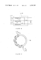
- FIG. 5 is a schematic diagram illustrating an inductor device utilized in the circuit of FIG. 4;
- FIG. 6 is a schematic perspective view of another embodiment of the invention.
- FIG. 7 is a schematic block circuit diagram of the embodiment shown in FIG. 6.
- the device 11 includes a housing 12 that defines a cable opening 13 and a plurality of socket openings 14. Retained in each of the socket openings 14 is a three-terminal socket 15-17 for receiving conventional three-terminal electrical plugs.
- a cord 18 extends through the cord opening 13 and retains three electrical conductors 21-23. Attached to the outer end of the cord 18 and connected to the conductors 21-23 is a conventional three-terminal electrical plug 25.
- FIG. 2 there is shown in block diagram form an electrical circuit retained by the housing 12.
- a combination surge suppressor and filter 26 is connected to the three conductors 21-23 of the electrical cord 18.
- a circuit 27 is also connected to the suppressor and filter combination 26 by a circuit 27 .
- a combination of three filters 28-30 connected in parallel. Each of the filters 28-30 is connected to a different one of the sockets 15-17.
- FIG. 3 shows in greater detail the combination suppressor and filter 26 shown in FIG. 2.
- Included in the combination 26 is a varistor 32 connected between the hot line 21 and the common line 23, a varistor 33 connected between the hot line 21 and the ground line 22 and a varistor 34 connected between the common line 23 and the ground line 22.
- a capacitor C1 connected between the hot line 21 and the ground line 22 and a capacitor C2 connected between the ground line 22 and the common line 23.
- the filters 28-30 are of identical construction and a circuit diagram of one 28 is shown in FIG. 4.
- An inductor L1 is connected in the hot line 21, an inductor L2 is connected in the ground line 22 and an inductor L3 is connected in the common line 23.
- a capacitor C3 is connected between the hot line 21 and the common line 23.
- the inductors L1, L2 and L3 are formed by winding the lines 21-23 on a common toroidal core 36.
- the inductors L1 and L3 are formed by a bifilar winding of the hot and common lines 21 and 23 while the inductor L2 is formed by separately winding the ground line 22.
- the plug 25 is inserted into a suitable AC power source and desired electronic equipment, for example a computer and peripheral accessores therefor, are individually plugged into the sockets 15-17.
- the varistors 32-34 prevent damage to the connected equipment by clipping line voltages above a given maximum, for example above 200 volts, and thereby suppress power line surges, spikes or transients. Differential surge voltage protection is provided by the varistor 32 while common mode line surge voltage protection is provided by the varistors 33 and 34.
- the filter portion of the combination 26 and the filters 28-30 function to isolate the connected equipment from performance degrading intermediate voltage spikes in the range between peak AC line voltage and the set point of the varistors 32-34.
- the permability of the toroid core 36 provides the inductors L1 and L3 with a high inductance that establishes power line isolation and the high inductance L2 isolates equipment ground and attenuates any interactive noise signal that appears on the grounds of the equipment connected to the sockets 15-17.
- Use of bifilar winding for the inductors L1 and L3 prevents saturation of the core 36 with high line currents.
- the device 11 provides a simple, compact unit that can effectively protect multiple pieces of electronic equipment from either damaging power line surges or performance degrading noise and interference.
- the embodiment 41 includes a housing 42 that defines a cord opening 43 and a plurality of receptacle openings 44. Extending through the cord opening 43 is an electrical cord 45 terminating with an electrical plug 46 adapted for insertion into an AC power source. A plurality of three-terminal electrical sockets 47-50 are retained by the socket openings 44.
- FIG. 7 Schematically illustrated in FIG. 7 is an electrical circuit 51 retained by the housing 42 of FIG. 6. Included in the circuit 51 is a surge suppressor and filter combination 52 that is connected to the electrical cord 45 and is identical to the circuit illustrated in FIG. 3. A circuit 53 connects a pair of filters 54 and 55 in a parallel combination that is connected to the surge suppressor and filter combination 52. Each of the filters 54 and 55 is identical to the filter 28 shown in FIG. 4. Connected to the filter 55 is a parallel combination of the sockets 47 and 48 while a parallel combination of the sockets 49 and 50 is connected to the filter 54.
- the combination 41 is used in a similar fashion to the embodiment 11 shown in FIG. 1. Again, the unit 41 is energized by insertion of the plug 46 into a suitable AC power source. A plurality of electrical devices can then be energized from the electrical sockets 47-50.
- the surge suppressor and filter combination 52 provides line surge protection and common mode bypassing in the same manner as the surge suppressor and filter combination 26 of FIG. 2.
- the filters 54 and 55 provide electrical isolation for the equipment connected to the sockets 47-50 in the same manner as the filters 28-30 of FIG. 2. However, in embodiment 41 complete isolation is not provided between the particular devices connected to the sockets 47 and 48 or between the devices connected to the sockets 49 and 50.
- the embodiment 41 is used in those instances in which complete filter isolation is not required between all individual units of an electrical system.
Abstract
The invention is an electronic isolation and surge suppression system including a housing defining cord and socket openings and retaining a surge suppressor connected to one end of an electrical cord, the other end of which terminates with a plug adapted for connection to an AC power source. Also retained by the housing are a plurality of multiple terminal electrical socket means and an electrical circuit connecting the sockets in a parallel combination that is in series with the suppressor. The electrical circuit includes an electrical filter connected between each of the socket means and the suppressor. Large voltage surges are eliminated by the suppressor, while the individual filters provide electrical isolation between electronic equipment connected to the individual sockets and isolation from AC power line noise and transients.
Description
This invention relates generally to the protection of electrical equipment and, more particularly, to a combination isolator and line surge suppressor for electronic devices.
A well-known cause of damage to electrical equipment is the high voltage line surge. Such line surges often produce voltages above the rated capacity of electronic components and can either produce catastrophic failure thereof or a gradual weakening that ultimately leads to failure. In addition to component failure, line surges can introduce electrical interference that degrades the performance of many devices including scientific instruments, test apparatus, chemical process controllers and data handlers, audio equipment, video recorders and television equipment. Particularly affected by interference are computers and computer peripheral equipment in which electrical noise can introduce inadvertent bits that ruin programs. Although devices are available for adequately suppressing line surges, such devices fail to eliminate effectively the above-described performance degrading interference in electrical equipment. Although conventional suppressors function to eliminate voltage spikes above a given maximum level they fail to eliminate voltage transients in the range between peak line voltage and that given maximum level. Such voltage transients can produce the performance degrading interference described above. Thus, presently available surge suppressors do not satisfactorily eliminate the problem.
The object of this invention, therefore, is to provide a device that will both protect and prevent faulty operation of various types of electronic equipment.
The invention is an electronic isolation and surge suppression system including a housing defining cord and socket openings and retaining a surge suppressor connected to one end of an electrical cord, the other end of which terminates with a plug adapted for connection to an AC power source. Also retained by the housing are a plurality of multiple terminal electrical socket means and an electrical circuit connecting the sockets in a parallel combination that is in series with the suppressor. The electrical circuit includes an electrical filter connected between each of the socket means and the suppressor. Large voltage surges are eliminated by the suppressor, while the individual filters provide electrical isolation between electronic equipment connected to the individual sockets. Thus, the invention provides a compact unit that substantially eliminates high voltage transients that could either damage or degrade the performance of electronic equipment.
In a preferred embodiment of the invention, the suppressor comprises a varistor connected between each pair of lines in a three-wire system and each filter comprises three inductor windings each connected in one line of the three-wire system and all wound on a common toroidal core. The suppressor provides both differential and common mode surge voltage protection while the use of an inductor in the ground line as well as in the hot and common lines effectively eliminates degrading intermediate voltage transients in the equipment connected to the sockets.
One feature of the above invention comprises a filter with hot and common line inductors bifilar wound on the common core so as to prevent core saturation with high line current. Also, additional isolation is provided by capacitors connected between each pair of lines in the three-wire system.
These and other objects and features of the present invention will become more apparent upon a perusal of the following description taken in conjunction with the accompanying drawings wherein:
FIG. 1 is a schematic perspective view of one embodiment of the invention;
FIG. 2 is a schematic block circuit diagram of the embodiment shown in FIG. 1;
FIG. 3 is a schematic circuit diagram of the suppressor shown in FIG. 2;
FIG. 4 is a schematic circuit diagram of one of the filters shown in FIG. 2;
FIG. 5 is a schematic diagram illustrating an inductor device utilized in the circuit of FIG. 4;
FIG. 6 is a schematic perspective view of another embodiment of the invention; and
FIG. 7 is a schematic block circuit diagram of the embodiment shown in FIG. 6.
Referring now to FIG. 1, there is shown an electrical isolation and surge suppression device 11 according to the invention. The device 11 includes a housing 12 that defines a cable opening 13 and a plurality of socket openings 14. Retained in each of the socket openings 14 is a three-terminal socket 15-17 for receiving conventional three-terminal electrical plugs. A cord 18 extends through the cord opening 13 and retains three electrical conductors 21-23. Attached to the outer end of the cord 18 and connected to the conductors 21-23 is a conventional three-terminal electrical plug 25.
Referring now to FIG. 2, there is shown in block diagram form an electrical circuit retained by the housing 12. A combination surge suppressor and filter 26 is connected to the three conductors 21-23 of the electrical cord 18. Also connected to the suppressor and filter combination 26 by a circuit 27 is a combination of three filters 28-30 connected in parallel. Each of the filters 28-30 is connected to a different one of the sockets 15-17. FIG. 3 shows in greater detail the combination suppressor and filter 26 shown in FIG. 2. Included in the combination 26 is a varistor 32 connected between the hot line 21 and the common line 23, a varistor 33 connected between the hot line 21 and the ground line 22 and a varistor 34 connected between the common line 23 and the ground line 22. Also in the combination 26 is a capacitor C1 connected between the hot line 21 and the ground line 22 and a capacitor C2 connected between the ground line 22 and the common line 23.
The filters 28-30 are of identical construction and a circuit diagram of one 28 is shown in FIG. 4. An inductor L1 is connected in the hot line 21, an inductor L2 is connected in the ground line 22 and an inductor L3 is connected in the common line 23. Also a capacitor C3 is connected between the hot line 21 and the common line 23. As illustrated in FIG. 5, the inductors L1, L2 and L3 are formed by winding the lines 21-23 on a common toroidal core 36. The inductors L1 and L3 are formed by a bifilar winding of the hot and common lines 21 and 23 while the inductor L2 is formed by separately winding the ground line 22.
During use of the device 11, the plug 25 is inserted into a suitable AC power source and desired electronic equipment, for example a computer and peripheral accessores therefor, are individually plugged into the sockets 15-17. The varistors 32-34 prevent damage to the connected equipment by clipping line voltages above a given maximum, for example above 200 volts, and thereby suppress power line surges, spikes or transients. Differential surge voltage protection is provided by the varistor 32 while common mode line surge voltage protection is provided by the varistors 33 and 34. In addition, the filter portion of the combination 26 and the filters 28-30 function to isolate the connected equipment from performance degrading intermediate voltage spikes in the range between peak AC line voltage and the set point of the varistors 32-34. The permability of the toroid core 36 provides the inductors L1 and L3 with a high inductance that establishes power line isolation and the high inductance L2 isolates equipment ground and attenuates any interactive noise signal that appears on the grounds of the equipment connected to the sockets 15-17. Use of bifilar winding for the inductors L1 and L3 prevents saturation of the core 36 with high line currents.
Additional protection is provided by the capacitors C1-3 that filter out AC power line hash and noise that may be detrimental to the connected equipment. The capacitors C1 and C2 provide common mode bypassing while the capacitor C3 provides differential bypassing. Thus, the device 11 provides a simple, compact unit that can effectively protect multiple pieces of electronic equipment from either damaging power line surges or performance degrading noise and interference.
Referring now to FIG. 6, there is shown another embodiment 41 of the invention. The embodiment 41 includes a housing 42 that defines a cord opening 43 and a plurality of receptacle openings 44. Extending through the cord opening 43 is an electrical cord 45 terminating with an electrical plug 46 adapted for insertion into an AC power source. A plurality of three-terminal electrical sockets 47-50 are retained by the socket openings 44.
Schematically illustrated in FIG. 7 is an electrical circuit 51 retained by the housing 42 of FIG. 6. Included in the circuit 51 is a surge suppressor and filter combination 52 that is connected to the electrical cord 45 and is identical to the circuit illustrated in FIG. 3. A circuit 53 connects a pair of filters 54 and 55 in a parallel combination that is connected to the surge suppressor and filter combination 52. Each of the filters 54 and 55 is identical to the filter 28 shown in FIG. 4. Connected to the filter 55 is a parallel combination of the sockets 47 and 48 while a parallel combination of the sockets 49 and 50 is connected to the filter 54.
The combination 41 is used in a similar fashion to the embodiment 11 shown in FIG. 1. Again, the unit 41 is energized by insertion of the plug 46 into a suitable AC power source. A plurality of electrical devices can then be energized from the electrical sockets 47-50. The surge suppressor and filter combination 52 provides line surge protection and common mode bypassing in the same manner as the surge suppressor and filter combination 26 of FIG. 2. In addition, the filters 54 and 55 provide electrical isolation for the equipment connected to the sockets 47-50 in the same manner as the filters 28-30 of FIG. 2. However, in embodiment 41 complete isolation is not provided between the particular devices connected to the sockets 47 and 48 or between the devices connected to the sockets 49 and 50. The embodiment 41 is used in those instances in which complete filter isolation is not required between all individual units of an electrical system.
Obviously, many modifications and variations of the present invention are possible in light of the above teachings. For example only, cascaded filters could be substituted for individual filters or the number of parallel filters in a given unit can be increased as desired. Similarly, the number of individual sockets connected to a given filter in the embodiment 41 can be increased as desired. It is to be understood, therefore, that the invention can be practiced otherwise than as specifically described.
Claims (8)
1. An electronic isolation and surge suppression system comprising:
a housing defining a connector opening and a plurality of socket openings;
an electrical connector extending through said connector opening and comprising a plurality of electrical conductors, each having one end located externally of said housing and an opposite end located internally thereof; said externally located ends adapted for connection to a source of AC power;
a voltage surge suppressor means disposed within said housing and connected to said internal ends of said conductors;
a plurality of multiple terminal electrical socket means mounted in said socket openings and adapted to receive electrical plugs; and
electrical circuit means connecting said socket means in a parallel combination and connecting said parallel combination in series with said suppressor means, said circuit means comprising a separate electrical filter means connected between each of said socket means and said suppressor means.
2. A system according to claim 1 wherein said suppressor means comprises voltage clipper means connected between said conductors.
3. A system according to claim 2 wherein said circuit means comprises a plurality of electrical lines connecting the multiple terminals of each of said socket means to said electrical conductors, and said filter means comprises an inductor in each of said lines.
4. A system according to claim 3 wherein said electrical conductors comprise three electrical conductors, and said circuit means comprise those lines connecting each of said socket means to said conductors.
5. A system according to claim 4 wherein all of said lines connecting one of said socket means to said conductors are wound on a common toroidal core to form said inductors.
6. A system according to claim 5 wherein each of said socket means comprises a plurality of multiple terminal electrical sockets connected in parallel.
7. A system according to claim 4 wherein said clipper means comprises a clipper connected between each pair of said three conductors.
8. A system according to claim 7 wherein said clippers are varistors.
Priority Applications (1)
| Application Number | Priority Date | Filing Date | Title |
|---|---|---|---|
| US06/024,379 US4259705A (en) | 1979-03-27 | 1979-03-27 | Combination surge suppressor filter |
Applications Claiming Priority (1)
| Application Number | Priority Date | Filing Date | Title |
|---|---|---|---|
| US06/024,379 US4259705A (en) | 1979-03-27 | 1979-03-27 | Combination surge suppressor filter |
Publications (1)
| Publication Number | Publication Date |
|---|---|
| US4259705A true US4259705A (en) | 1981-03-31 |
Family
ID=21820284
Family Applications (1)
| Application Number | Title | Priority Date | Filing Date |
|---|---|---|---|
| US06/024,379 Expired - Lifetime US4259705A (en) | 1979-03-27 | 1979-03-27 | Combination surge suppressor filter |
Country Status (1)
| Country | Link |
|---|---|
| US (1) | US4259705A (en) |
Cited By (55)
| Publication number | Priority date | Publication date | Assignee | Title |
|---|---|---|---|---|
| WO1985000079A1 (en) * | 1983-06-16 | 1985-01-03 | Limitorque Limited | Electrical circuit for switching a multi-phase a.c. supply to a load |
| US4584622A (en) * | 1984-07-09 | 1986-04-22 | Gte Products Corporation | Transient voltage surge suppressor |
| US4616286A (en) * | 1982-08-02 | 1986-10-07 | Puroflow Corporation | Power line filter |
| FR2582875A1 (en) * | 1985-05-29 | 1986-12-05 | Baudry Jean | Plug or insert unit with multiple protection to be connected to a network socket |
| US4628394A (en) * | 1984-07-09 | 1986-12-09 | Gte Products Corporation | Voltage surge suppressor |
| US4649457A (en) * | 1984-02-17 | 1987-03-10 | B. H. Tytewadd Marketing, Incorporated | Surge protection device |
| US4667173A (en) * | 1985-08-29 | 1987-05-19 | Kabushiki Kaisha Toshiba | Line filter |
| US4675772A (en) * | 1984-05-07 | 1987-06-23 | Epstein Barry M | Protector network for A-C equipment |
| DE3604049A1 (en) * | 1986-02-08 | 1987-08-13 | Josef Schmitz | Overvoltage protection device |
| US4698721A (en) * | 1983-11-07 | 1987-10-06 | Puroflow Corp. | Power line filter for transient and continuous noise suppression |
| US4723115A (en) * | 1985-10-11 | 1988-02-02 | Robert Apter | Power line cord filtering assembly |
| WO1988001800A1 (en) * | 1986-08-27 | 1988-03-10 | Kitchens William B | A.c.-d.c. spike eliminating bandpass filter |
| US4743997A (en) * | 1986-12-22 | 1988-05-10 | Carpenter Jr Roy B | High-voltage systems surge eliminators for transmission lines and distribution station protection |
| EP0268770A1 (en) * | 1986-09-30 | 1988-06-01 | Siemens Aktiengesellschaft | Radioshielded DC commutator motor |
| US4751607A (en) * | 1986-08-11 | 1988-06-14 | American Telephone And Telegraph Company | Communication line transient protection |
| FR2609580A1 (en) * | 1987-01-08 | 1988-07-15 | Finzel Jean Luc | Lightning-arrester module for protection against industrial overvoltages |
| US4760356A (en) * | 1986-04-15 | 1988-07-26 | Leigh Instruments Limited | Power line filter |
| EP0300872A1 (en) * | 1987-07-23 | 1989-01-25 | Merlin Gerin | Filtering device for common types disturbances acting on a static power converter's electronic cards |
| US4802055A (en) * | 1987-10-26 | 1989-01-31 | Joseph L. Brooks Manufacturing Corp. | Transient voltage surge suppressor |
| US4814941A (en) * | 1984-06-08 | 1989-03-21 | Steelcase Inc. | Power receptacle and nested line conditioner arrangement |
| US4861286A (en) * | 1987-07-27 | 1989-08-29 | Acco World Corporation | Electrical connector device |
| US4872081A (en) * | 1988-10-11 | 1989-10-03 | Pass & Seymour, Inc. | Duplex electrical receptacle with voltage surge suppression |
| US4878145A (en) * | 1988-11-21 | 1989-10-31 | Oneac Corporation | Surge/transient protector for a plurality of data lines |
| US4999729A (en) * | 1989-08-09 | 1991-03-12 | Stifter Francis J | Satellite receiver protection apparatus |
| US4999594A (en) * | 1988-12-09 | 1991-03-12 | Condor, Inc. | AC line filter with tapped balun winding |
| US5105327A (en) * | 1990-05-10 | 1992-04-14 | Uses, Inc. | Ac power conditioning circuit |
| US5115368A (en) * | 1991-05-15 | 1992-05-19 | Smith Lawrence C | AC power strip with grounded digital and ground isolated accessory receptacles |
| US5153806A (en) * | 1989-06-07 | 1992-10-06 | Corey Lawrence G | Transient surge suppressor and alarm signal circuit |
| US5206779A (en) * | 1990-10-01 | 1993-04-27 | Okaya Electric Industries Co., Ltd. | Noise filter with surge absorber and surge absorber attached to noise filter |
| US5210523A (en) * | 1991-02-27 | 1993-05-11 | Fire-Lite Alarms, Inc. | Noise suppression system and method |
| US5257157A (en) * | 1990-05-04 | 1993-10-26 | Epstein Barry M | Protector network for A-C equipment |
| US5323304A (en) * | 1992-01-27 | 1994-06-21 | Georator Corporation | A.C. storage module for reducing harmonic distortion in an A.C. waveform |
| US5327316A (en) * | 1990-10-09 | 1994-07-05 | The United States Of America As Represented By The Secretary Of The Navy | Power terminal protection device |
| FR2704686A1 (en) * | 1993-04-30 | 1994-11-04 | Oneill Andre | Method and device for securing an energy distribution point, especially an electrical socket, and electrical appliances including this device |
| WO1994027348A1 (en) * | 1993-05-13 | 1994-11-24 | Neill Andre O | Method for making a power distribution point safe, particularly an electrical socket, device therefor and electrical equipment incorporating said device |
| US5570006A (en) * | 1992-01-27 | 1996-10-29 | Power Distribution, Inc. | A.C. storage module for reducing harmonic distortion in an A.C. waveform |
| US5617284A (en) * | 1994-08-05 | 1997-04-01 | Paradise; Rick | Power surge protection apparatus and method |
| US5719734A (en) * | 1994-09-16 | 1998-02-17 | Morton International, Inc. | Electronic apparatus |
| US5856740A (en) * | 1997-05-09 | 1999-01-05 | Emerson Electric Co. | Shunt voltage regulator with a variable load unit |
| US5969583A (en) * | 1996-12-23 | 1999-10-19 | Acuson Corporation | Common-mode EMI filter with a separately wound ground winding |
| US6388852B1 (en) | 1999-02-17 | 2002-05-14 | Gerry Bobash | Flicker protection circuit |
| US6480604B1 (en) | 1999-10-01 | 2002-11-12 | Porta Systems Corporation | Balanced spectrum limiter for telephone and communication systems and protection module incorporating the same |
| US20030190844A1 (en) * | 2002-04-03 | 2003-10-09 | Arthur Foux | Portable multibranch protective extension cord |
| EP1617538A1 (en) * | 2003-03-31 | 2006-01-18 | Obschestvo S Ogranichennoy Otvetstvennostju "Algoritm" | Device for suppressing radiation occurring during information transmission through power supply lines |
| US20060146463A1 (en) * | 2005-01-04 | 2006-07-06 | Demian Martin | In-wall power system and method |
| US20070230080A1 (en) * | 2002-01-02 | 2007-10-04 | Ruggedcom Inc. | Environmentally hardened ethernet switch |
| US20080227318A1 (en) * | 2003-12-23 | 2008-09-18 | Bsh Bosch Und Siemens Hausgerate Gmbh | Connector Device for Producing an Electrical Connection Between a Mains Cable and a Loom |
| US20090207540A1 (en) * | 2008-02-14 | 2009-08-20 | Primax Electronics Ltd. | Power strip having surge protective circuit |
| EP2462663A1 (en) * | 2009-08-07 | 2012-06-13 | Panasonic Corporation | Plug receptacle |
| EP2568352A3 (en) * | 2011-09-06 | 2013-04-24 | Ricoh Company, Ltd. | Power supplying unit and image forming apparatus |
| US20140139349A1 (en) * | 2012-11-19 | 2014-05-22 | Baker Hughes Incorporated | Systems and Methods for Detecting and Communicating Failure of Integral Surge Suppression in Drive Systems for Downhole Equipment |
| US8791782B2 (en) | 2011-01-28 | 2014-07-29 | Uses, Inc. | AC power conditioning circuit |
| US8866575B2 (en) | 2011-01-28 | 2014-10-21 | Uses, Inc. | AC power conditioning circuit |
| US20150372416A1 (en) * | 2014-06-20 | 2015-12-24 | Icon Health & Fitness, Inc. | Adapter with an Electronic Filtering System |
| US10212994B2 (en) | 2015-11-02 | 2019-02-26 | Icon Health & Fitness, Inc. | Smart watch band |
Citations (8)
| Publication number | Priority date | Publication date | Assignee | Title |
|---|---|---|---|---|
| US2939095A (en) * | 1957-02-26 | 1960-05-31 | Sprague Electric Co | Line filter |
| US2943272A (en) * | 1958-01-02 | 1960-06-28 | Nathan W Feldman | Crosstalk cancellation in signal communication system |
| US3372285A (en) * | 1964-10-09 | 1968-03-05 | Westinghouse Air Brake Co | Transient voltage suppressors |
| US3693053A (en) * | 1971-10-29 | 1972-09-19 | Gen Electric | Metal oxide varistor polyphase transient voltage suppression |
| US3705365A (en) * | 1971-02-11 | 1972-12-05 | Westinghouse Electric Corp | Common mode noise cancellation system |
| US4038990A (en) * | 1975-11-19 | 1977-08-02 | Medtronic, Inc. | Cautery protection circuit for a heart pacemaker |
| US4089032A (en) * | 1976-09-08 | 1978-05-09 | William Dell Orfano | Plug-type transient surge suppressor |
| US4095262A (en) * | 1976-12-27 | 1978-06-13 | St Clair Homer F | Lightning protection circuit |
-
1979
- 1979-03-27 US US06/024,379 patent/US4259705A/en not_active Expired - Lifetime
Patent Citations (8)
| Publication number | Priority date | Publication date | Assignee | Title |
|---|---|---|---|---|
| US2939095A (en) * | 1957-02-26 | 1960-05-31 | Sprague Electric Co | Line filter |
| US2943272A (en) * | 1958-01-02 | 1960-06-28 | Nathan W Feldman | Crosstalk cancellation in signal communication system |
| US3372285A (en) * | 1964-10-09 | 1968-03-05 | Westinghouse Air Brake Co | Transient voltage suppressors |
| US3705365A (en) * | 1971-02-11 | 1972-12-05 | Westinghouse Electric Corp | Common mode noise cancellation system |
| US3693053A (en) * | 1971-10-29 | 1972-09-19 | Gen Electric | Metal oxide varistor polyphase transient voltage suppression |
| US4038990A (en) * | 1975-11-19 | 1977-08-02 | Medtronic, Inc. | Cautery protection circuit for a heart pacemaker |
| US4089032A (en) * | 1976-09-08 | 1978-05-09 | William Dell Orfano | Plug-type transient surge suppressor |
| US4095262A (en) * | 1976-12-27 | 1978-06-13 | St Clair Homer F | Lightning protection circuit |
Cited By (65)
| Publication number | Priority date | Publication date | Assignee | Title |
|---|---|---|---|---|
| US4616286A (en) * | 1982-08-02 | 1986-10-07 | Puroflow Corporation | Power line filter |
| WO1985000079A1 (en) * | 1983-06-16 | 1985-01-03 | Limitorque Limited | Electrical circuit for switching a multi-phase a.c. supply to a load |
| US4698721A (en) * | 1983-11-07 | 1987-10-06 | Puroflow Corp. | Power line filter for transient and continuous noise suppression |
| US4649457A (en) * | 1984-02-17 | 1987-03-10 | B. H. Tytewadd Marketing, Incorporated | Surge protection device |
| US4675772A (en) * | 1984-05-07 | 1987-06-23 | Epstein Barry M | Protector network for A-C equipment |
| US4814941A (en) * | 1984-06-08 | 1989-03-21 | Steelcase Inc. | Power receptacle and nested line conditioner arrangement |
| US4584622A (en) * | 1984-07-09 | 1986-04-22 | Gte Products Corporation | Transient voltage surge suppressor |
| US4628394A (en) * | 1984-07-09 | 1986-12-09 | Gte Products Corporation | Voltage surge suppressor |
| FR2582875A1 (en) * | 1985-05-29 | 1986-12-05 | Baudry Jean | Plug or insert unit with multiple protection to be connected to a network socket |
| US4667173A (en) * | 1985-08-29 | 1987-05-19 | Kabushiki Kaisha Toshiba | Line filter |
| US4723115A (en) * | 1985-10-11 | 1988-02-02 | Robert Apter | Power line cord filtering assembly |
| DE3604049A1 (en) * | 1986-02-08 | 1987-08-13 | Josef Schmitz | Overvoltage protection device |
| US4760356A (en) * | 1986-04-15 | 1988-07-26 | Leigh Instruments Limited | Power line filter |
| US4751607A (en) * | 1986-08-11 | 1988-06-14 | American Telephone And Telegraph Company | Communication line transient protection |
| WO1988001800A1 (en) * | 1986-08-27 | 1988-03-10 | Kitchens William B | A.c.-d.c. spike eliminating bandpass filter |
| EP0268770A1 (en) * | 1986-09-30 | 1988-06-01 | Siemens Aktiengesellschaft | Radioshielded DC commutator motor |
| US4743997A (en) * | 1986-12-22 | 1988-05-10 | Carpenter Jr Roy B | High-voltage systems surge eliminators for transmission lines and distribution station protection |
| FR2609580A1 (en) * | 1987-01-08 | 1988-07-15 | Finzel Jean Luc | Lightning-arrester module for protection against industrial overvoltages |
| EP0300872A1 (en) * | 1987-07-23 | 1989-01-25 | Merlin Gerin | Filtering device for common types disturbances acting on a static power converter's electronic cards |
| FR2618617A1 (en) * | 1987-07-23 | 1989-01-27 | Merlin Gerin | DEVICE FOR FILTERING COMMON MODE DISTURBANCES AFFECTING THE CARDS OF A STATIC POWER CONVERTER |
| US4903185A (en) * | 1987-07-23 | 1990-02-20 | Merlin Gerin | Filtering device of the common mode disturbances affecting the printed circuit boards of a static power converter |
| US4861286A (en) * | 1987-07-27 | 1989-08-29 | Acco World Corporation | Electrical connector device |
| US4802055A (en) * | 1987-10-26 | 1989-01-31 | Joseph L. Brooks Manufacturing Corp. | Transient voltage surge suppressor |
| US4872081A (en) * | 1988-10-11 | 1989-10-03 | Pass & Seymour, Inc. | Duplex electrical receptacle with voltage surge suppression |
| US4878145A (en) * | 1988-11-21 | 1989-10-31 | Oneac Corporation | Surge/transient protector for a plurality of data lines |
| US4999594A (en) * | 1988-12-09 | 1991-03-12 | Condor, Inc. | AC line filter with tapped balun winding |
| US5153806A (en) * | 1989-06-07 | 1992-10-06 | Corey Lawrence G | Transient surge suppressor and alarm signal circuit |
| US4999729A (en) * | 1989-08-09 | 1991-03-12 | Stifter Francis J | Satellite receiver protection apparatus |
| US5257157A (en) * | 1990-05-04 | 1993-10-26 | Epstein Barry M | Protector network for A-C equipment |
| US5105327A (en) * | 1990-05-10 | 1992-04-14 | Uses, Inc. | Ac power conditioning circuit |
| US5206779A (en) * | 1990-10-01 | 1993-04-27 | Okaya Electric Industries Co., Ltd. | Noise filter with surge absorber and surge absorber attached to noise filter |
| US5327316A (en) * | 1990-10-09 | 1994-07-05 | The United States Of America As Represented By The Secretary Of The Navy | Power terminal protection device |
| US5210523A (en) * | 1991-02-27 | 1993-05-11 | Fire-Lite Alarms, Inc. | Noise suppression system and method |
| US5115368A (en) * | 1991-05-15 | 1992-05-19 | Smith Lawrence C | AC power strip with grounded digital and ground isolated accessory receptacles |
| US5323304A (en) * | 1992-01-27 | 1994-06-21 | Georator Corporation | A.C. storage module for reducing harmonic distortion in an A.C. waveform |
| US5570006A (en) * | 1992-01-27 | 1996-10-29 | Power Distribution, Inc. | A.C. storage module for reducing harmonic distortion in an A.C. waveform |
| FR2704686A1 (en) * | 1993-04-30 | 1994-11-04 | Oneill Andre | Method and device for securing an energy distribution point, especially an electrical socket, and electrical appliances including this device |
| WO1994027348A1 (en) * | 1993-05-13 | 1994-11-24 | Neill Andre O | Method for making a power distribution point safe, particularly an electrical socket, device therefor and electrical equipment incorporating said device |
| US5617284A (en) * | 1994-08-05 | 1997-04-01 | Paradise; Rick | Power surge protection apparatus and method |
| US5719734A (en) * | 1994-09-16 | 1998-02-17 | Morton International, Inc. | Electronic apparatus |
| US5969583A (en) * | 1996-12-23 | 1999-10-19 | Acuson Corporation | Common-mode EMI filter with a separately wound ground winding |
| US5856740A (en) * | 1997-05-09 | 1999-01-05 | Emerson Electric Co. | Shunt voltage regulator with a variable load unit |
| US6388852B1 (en) | 1999-02-17 | 2002-05-14 | Gerry Bobash | Flicker protection circuit |
| US6480604B1 (en) | 1999-10-01 | 2002-11-12 | Porta Systems Corporation | Balanced spectrum limiter for telephone and communication systems and protection module incorporating the same |
| US7443646B2 (en) * | 2002-01-02 | 2008-10-28 | Ruggedcom Inc. | Environmentally hardened ethernet switch |
| US20070230080A1 (en) * | 2002-01-02 | 2007-10-04 | Ruggedcom Inc. | Environmentally hardened ethernet switch |
| US20030190844A1 (en) * | 2002-04-03 | 2003-10-09 | Arthur Foux | Portable multibranch protective extension cord |
| EP1617538A1 (en) * | 2003-03-31 | 2006-01-18 | Obschestvo S Ogranichennoy Otvetstvennostju "Algoritm" | Device for suppressing radiation occurring during information transmission through power supply lines |
| EP1617538A4 (en) * | 2003-03-31 | 2007-05-09 | Obschestvo S Ogranichennoy Otv | Device for suppressing radiation occurring during information transmission through power supply lines |
| US20080227318A1 (en) * | 2003-12-23 | 2008-09-18 | Bsh Bosch Und Siemens Hausgerate Gmbh | Connector Device for Producing an Electrical Connection Between a Mains Cable and a Loom |
| US8794987B2 (en) * | 2003-12-23 | 2014-08-05 | Bsh Bosch Und Siemens Hausgeraete Gmbh | Connector device for producing an electrical connection between a mains cable and a loom |
| US20060146463A1 (en) * | 2005-01-04 | 2006-07-06 | Demian Martin | In-wall power system and method |
| US20090207540A1 (en) * | 2008-02-14 | 2009-08-20 | Primax Electronics Ltd. | Power strip having surge protective circuit |
| US8004811B2 (en) * | 2008-02-14 | 2011-08-23 | Primax Electronics Ltd. | Power strip having surge protective circuit |
| EP2462663A1 (en) * | 2009-08-07 | 2012-06-13 | Panasonic Corporation | Plug receptacle |
| EP2462663A4 (en) * | 2009-08-07 | 2013-11-27 | Panasonic Corp | Plug receptacle |
| CN102549851A (en) * | 2009-08-07 | 2012-07-04 | 松下电器产业株式会社 | Plug receptacle |
| US8791782B2 (en) | 2011-01-28 | 2014-07-29 | Uses, Inc. | AC power conditioning circuit |
| US8866575B2 (en) | 2011-01-28 | 2014-10-21 | Uses, Inc. | AC power conditioning circuit |
| EP2568352A3 (en) * | 2011-09-06 | 2013-04-24 | Ricoh Company, Ltd. | Power supplying unit and image forming apparatus |
| US20140139349A1 (en) * | 2012-11-19 | 2014-05-22 | Baker Hughes Incorporated | Systems and Methods for Detecting and Communicating Failure of Integral Surge Suppression in Drive Systems for Downhole Equipment |
| US9695685B2 (en) * | 2012-11-19 | 2017-07-04 | Baker Hughes Incorporated | Systems and methods for detecting and communicating failure of integral surge suppression in drive systems for downhole equipment |
| US20150372416A1 (en) * | 2014-06-20 | 2015-12-24 | Icon Health & Fitness, Inc. | Adapter with an Electronic Filtering System |
| US9948037B2 (en) * | 2014-06-20 | 2018-04-17 | Icon Health & Fitness, Inc. | Adapter with an electronic filtering system |
| US10212994B2 (en) | 2015-11-02 | 2019-02-26 | Icon Health & Fitness, Inc. | Smart watch band |
Similar Documents
| Publication | Publication Date | Title |
|---|---|---|
| US4259705A (en) | Combination surge suppressor filter | |
| US4760485A (en) | Zine oxide surge arresters | |
| US5689180A (en) | Isolated electrical power supply | |
| US4807083A (en) | Surge suppressor for coax cable and AC power lines | |
| US5142430A (en) | Power line filter and surge protection circuit components and circuits | |
| US5053910A (en) | Surge suppressor for coaxial transmission line | |
| US4584622A (en) | Transient voltage surge suppressor | |
| US4802055A (en) | Transient voltage surge suppressor | |
| US7136270B2 (en) | Surge protector including data pass-through | |
| KR101438120B1 (en) | Protection devices for power line against high altitude electromagnetic pulse | |
| US6385029B1 (en) | Total electrical transient eliminator | |
| GB2293058A (en) | Surge arrestor for RF devices | |
| JP2003283390A (en) | Inductor loading apparatus for power line carrier communication | |
| JP2571947Y2 (en) | Electromagnetic protection filter device for terminal equipment | |
| US6480604B1 (en) | Balanced spectrum limiter for telephone and communication systems and protection module incorporating the same | |
| US20040264712A1 (en) | Method and apparatus for eliminating noise in an electrical circuit | |
| KR102311307B1 (en) | Emp protective device for rf antenna | |
| JPS61287101A (en) | Protective apparatus for electric circuit | |
| CA2240414C (en) | Isolated electrical power supply | |
| JP3617660B2 (en) | Isolation transformer | |
| JPH0629226U (en) | High frequency common mode noise filter for multi-core communication line | |
| JPH059023U (en) | Motor noise prevention circuit | |
| JPS63207067A (en) | Noise cutting system | |
| JPS59129530A (en) | Surge noise absorber | |
| JPS6074305A (en) | Noise removing ac power source connecting cable |
Legal Events
| Date | Code | Title | Description |
|---|---|---|---|
| AS | Assignment |
Owner name: ELECTRONIC SPEC1ALISTS,INC.A CORP.OF.MA.. Free format text: ASSIGNMENT OF ASSIGNORS INTEREST.;ASSIGNOR:STIFTER, FRANCIS J.;REEL/FRAME:003896/0077 Effective date: 19810722 |