US4305130A - Apparatus and method to enable a robot with vision to acquire, orient and transport workpieces - Google Patents
Apparatus and method to enable a robot with vision to acquire, orient and transport workpieces Download PDFInfo
- Publication number
- US4305130A US4305130A US06/043,197 US4319779A US4305130A US 4305130 A US4305130 A US 4305130A US 4319779 A US4319779 A US 4319779A US 4305130 A US4305130 A US 4305130A
- Authority
- US
- United States
- Prior art keywords
- workpiece
- hand
- data
- pose
- bin
- Prior art date
- Legal status (The legal status is an assumption and is not a legal conclusion. Google has not performed a legal analysis and makes no representation as to the accuracy of the status listed.)
- Expired - Lifetime
Links
Images


Classifications
-
- G—PHYSICS
- G06—COMPUTING; CALCULATING OR COUNTING
- G06T—IMAGE DATA PROCESSING OR GENERATION, IN GENERAL
- G06T1/00—General purpose image data processing
- G06T1/0014—Image feed-back for automatic industrial control, e.g. robot with camera
-
- B—PERFORMING OPERATIONS; TRANSPORTING
- B25—HAND TOOLS; PORTABLE POWER-DRIVEN TOOLS; MANIPULATORS
- B25J—MANIPULATORS; CHAMBERS PROVIDED WITH MANIPULATION DEVICES
- B25J19/00—Accessories fitted to manipulators, e.g. for monitoring, for viewing; Safety devices combined with or specially adapted for use in connection with manipulators
- B25J19/02—Sensing devices
- B25J19/021—Optical sensing devices
- B25J19/023—Optical sensing devices including video camera means
-
- G—PHYSICS
- G05—CONTROLLING; REGULATING
- G05B—CONTROL OR REGULATING SYSTEMS IN GENERAL; FUNCTIONAL ELEMENTS OF SUCH SYSTEMS; MONITORING OR TESTING ARRANGEMENTS FOR SUCH SYSTEMS OR ELEMENTS
- G05B2219/00—Program-control systems
- G05B2219/30—Nc systems
- G05B2219/40—Robotics, robotics mapping to robotics vision
- G05B2219/40053—Pick 3-D object from pile of objects
-
- G—PHYSICS
- G05—CONTROLLING; REGULATING
- G05B—CONTROL OR REGULATING SYSTEMS IN GENERAL; FUNCTIONAL ELEMENTS OF SUCH SYSTEMS; MONITORING OR TESTING ARRANGEMENTS FOR SUCH SYSTEMS OR ELEMENTS
- G05B2219/00—Program-control systems
- G05B2219/30—Nc systems
- G05B2219/40—Robotics, robotics mapping to robotics vision
- G05B2219/40583—Detect relative position or orientation between gripper and currently handled object
Definitions
- the present invention is directed to a robot system and a method of using the same, which system acquires a workpiece from randomly arranged workpieces by examining data which matches holdsites and places the acquired workpiece at a goal site.
- the system does not require complete knowledge of the position and orientation of a workpiece in a bin.
- the system broadly includes a robot assembly having an arm and hand (gripper) for sequentially engaging the workpieces, a sensing system for collecting data about the workpieces in different states and a computer which communicates with both the assembly and the sensing system and controls the movement of the robot assembly.
- the robot assembly includes a hand to engage the unoriented workpieces and an arm to translate and rotate the hand.
- the transfer of a workpiece from a bin to a final goal site embodies a plurality of steps after the robot system has been calibrated and initialized.
- initialization a base coordinate system is established, an image coordinate system is established and certain poses and trajectories (spatial relationships of the hand to workpiece to supply bin and goal sites and hand and/or workpiece to supply bin and goal sites) are established.
- the imaging system views the bin and candidate holdsites are established. These holdsites are potential surfaces on the workpiece which the hand can engage. The hand moves into contacting engagement with a holdsite on a piece and engages the workpiece. The workpiece is then removed from the bin.
- the position and orientation of the workpiece in the hand is determined.
- the hand moves to a predetermined position and orientation, the presentation pose and the imaging system views the workpiece.
- the hand is now in the presentation pose.
- Features are extracted from the image data.
- the features are then compared with features obtained with a workpiece at standard position and orientation.
- the pose of the workpiece is computed.
- the workpiece is then moved to an intermediate goal site with compensation being made for workpiece rotation and translation. After transferring the workpiece to an intermediate goal site, it can be moved through a fixed trajectory to a final goal site.
- the invention comprises a robot assembly (arm and hand), the arm adapted for movement through at least two linear orthogonal axes and through at least two rotary axes; a video camera to image workpieces in a bin and a computer for control and computation.
- the camera views the bin.
- a binary image of the workpieces in the bin is obtained by setting all pixels whose brightness is below a threshold to zero, the rest to one.
- Solid regions (of ones) corresponding to the surface area of the hand are defined as candidate holdsites, and one holdsite of the holdsites is transformed into base coordinates. The arm is moved and the hand descends and contacts the holdsite thus engaging the workpiece.
- an acquired workpiece is moved to a presentation pose where it is viewed by a video camera.
- An image of the workpiece is obtained and compared with a pre-established image.
- the pose of the workpiece is computed.
- the workpiece is transferred to an intermediate goal site and then moved through a fixed trajectory to a final goal site.
- FIG. 1 is a functional block diagram of a robot system embodying the invention
- FIG. 2 is a schematic illustration of an arm, wrist and hand assembly with translational and orthogonal axes defined thereon;
- FIG. 3 illustrates the relationship between the base coordinate system of the robot assembly
- FIG. 4 is a flowchart of a program for an arm joint solution for the robot assembly of FIG. 3;
- FIG. 5 is a schematic illustration of the relationship between the base coordinate system and the image cordinates of the video cameras
- FIG. 6 is a schematic illustration of a workpiece held in the presentation pose
- FIGS. 7 and 8 illustrate alternative intermediate goal sites.
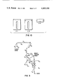
- FIG. 9 is a representation of an image of candidate holdsites on workpieces in a bin.
- FIG. 10 are views of a workpiece in various presentation poses
- FIGS. 11 and 12 are flow charts of intermediate goal sites.
- a robot system 10 embodying the invention is shown functionally in FIG. 1 and comprises robot assembly 20; an imaging system 40, a computer 60 and a data source 70.
- the robot assembly transfers workpieces 80 from a supply bin 82 to one of two intermediate goal sites 100 and 110, respectively; and to a final goal site 130.
- the control of the computer 60 is accomplished through the instructions.
- the instructions are written in terms of the particular mode of operation desired.
- the computer thus has stored in its memory, the programs or routines corresponding to each mode or operation of the computer.
- the computer comprises suitable control, storage and computational units for performing various arithmetic and logical functions on data which it processes in digital form. Any standard computer language consistent with the capability of the computer can be used for the instructions. All subroutines are not described in detail, since they can be written in any desired notations, formats or sequence, depending upon the particular computer being utilized, computer language, etc. Programs and instructions described before are put in terms of structural flow. When necessary and applicable for purposes of the invention, individual programs are described.
- the computer 60 interfaces with a robot assembly controller 30 through an interface 62 such as a 16 bit I/O Module (CAI Model 13213-00).
- the imaging system 40 comprises two video cameras 42 and 44 (FIG. 2) both of which interface with the computer 60 through an interface 64 such as a direct memory access board.
- the computer has a sixteen bit wordlength, software floating point arithmetic and 32K words of memory. All image processing and robot assembly computations are performed in the computer. Arm joint servoing is effected by a keyboard 32.
- Programs are written in both FORTRAN and assembly language modules.
- the assembly language modules are used to implement the interface handlers and to perform manipulations which are not suited for FORTRAN such as byte (eight bit) mode arithmetic and bit-based computations.
- the robot assembly 20 consists of the arm 22, and hand 26, and possesses six degrees of freedom about 3 linear orthogonal axes (X, Y, Z) and 3 rotary axes ( ⁇ 4, ⁇ 5, ⁇ 6).
- the arm is defined as including a wrist 24.
- the linear axes of the arm 22 are defined by three positioning tables, such as Anorad positioning tables 28. As is well known, the position of these tables along the three axes is measured by a rotary encoder which produces a dual channel sinusoidal wave and has a resolution of 0.001 inch per encoder count.
- the controller (servo control system not shown) embodied in the tables, interfaces with the computer 60 via a sixteen bit I/O board. The digital interface accpets the following commands:
- Axis select--selects one of the six axes.
- Position command--these signals indicate absolute position in binary.
- Limit switch interrupt--indicates that an axis hit a limit.
- the front panel of the controller includes an LED readout that reflects the current position of each axis.
- a ready and limit indicator are also mounted on the front panel for each axis.
- the wrist 24 adapted for motion about the three rotary joint axis is secured to arm 22.
- the 04 axis rotates through 286°; the 05 axis through 233° and the 06 axis through 310°.
- Encoder units have a two channel, 250 pulses per revolution, sinusoidal wave output.
- the controller 30 multiplies the encoder output by four, which results in an angular resolution of 0.36 degrees per pulse.
- the limit switches associated with the axes of the wrist communicate with and are controlled by the controller 30 associated with the tables.
- the specifications for the particular arm and wrist are described in "General Methods to Enable Robots with Vision to Acquire, Orient and Transport Workpieces", Fourth Report, J. Birk et al., Appendix 5, presented at the proceedings Eighth International Synposium on Industrial Robots, Stuttgart, Germany, May 30-June 1, 1978, which Report including Appendices is hereby incorporated by reference in this application in its entirety.
- the vacuum cup 28 is flexibly secured, such as by a compression spring 29 to a piston-cylinder arrangement within the hand 26.
- the compression spring 29 allows flexibility of the vacuum cup in selecting randomly-orientated workpieces. Once a workpiece is engaged, the compression spring-vacuum cup is withdrawn into the wrist and locked.
- the three rotary joints are designed so that the three axes of rotation intersect at a point, the wrist center.
- the structure of the flowchart presented in FIG. 4 exhibits two major branches.
- the left branch corresponds to the general case where two sets of angle values are obtained.
- This degeneracy occurs because under this kinematic condition, the axes for ⁇ 4 and ⁇ 6 are collinear. Hence, only the combined value of rotation angle, ⁇ 4 ,6, can be determined and many assignments of ⁇ 4 and ⁇ 6 are possible.
- There is also a degeneracy for ⁇ 5 180°. This corresponds to the hand pointing straight up.
- the two conditions are summarized below as
- the video camera 42 is secured to the arm 22 and its optical axis (line of sight) is parallel to the Z axis. Illumination of the workpiece is provided by lamps 43.
- the video camera 44 the workstation camera, is rigidly mounted and faces parallel to the X 0 axis. Both cameras are aligned with the robot assembly axes of motion x,y and z to simplify the transformations from camera to robot coordinates, as shown most clearly in FIG. 5. Illumination of the workpiece symetrical about the optical axis is provided by lamps 45.
- the first camera 42 is used to select holdsights on workpieces 80 in the bin 82. Because it is mounted on the arm it can also be used to view workpieces nearly anywhere in the bin 82 and goal sites 100, 110 and 130.
- the second camera 44 is used to compute the workpiece presentation pose in the hand 26.
- the arm is positioned such that the hand is vertically above the holdsite. This position is easily achieved because movements of the robot along the X 0 or Y 0 axis correspond to movements of the picture image along the X a or Y a axis, respectively. Given this alignment (FIG. 5), the following camera parameters are required:
- the conversion factors (encoder counts/pixel) in the X and Y directions (Cepx, Cepy). Because the camera has a square lattice of sensors, the arm 22 has equal resolution in the X 0 and Y 0 directions, and the X 0 Y 0 and X a Y a planes are nearly parallel, these two conversion factors should be equal.
- x 0 , y 0 , x a , and y a are coordinates of a vertical line passing through the hand (x 00 , y 00 , x a0 , and y a0 ) and a visible object.
- the robot assembly values X,Y that position the hand over a specific holdsite with image coordinates x h , y h are obtained as
- Arm camera 42 alignment is achieved by a rotation about the camera axis.
- a. Position a calibration piece in the bin, such as, a white circular chip on a black background.
- step f The camera is aligned.
- step c The same procedure of step c is repeated but with 8 points in each direction.
- a regression algorithm over the CG's trajectory will give the conversion factors in each direction (C epx , C epy ).
- Steps b, c, and f are automatic. Placement of the calibration piece, rotation of the camera, and decisions about alignment are operator tasks. On a TV monitor, the operator can also reject poor images or ones with only parts of the piece. A typical trajectory for the center of gravity is shown in Table I. Joint coordinates and image coordinates of the vertical line which passes through the chip are obtained as follows:
- the work station camera 44 is used to obtain a view of the workpiece in the hand. From this view a set of features is extracted and compared with a similar set for a taught presentation pose. One of the finite number of states of the workpiece in the hand is recognized. The difference between the position and orientation of the two feature sets can be converted into a translation and a rotation on the plane on which the workpiece is held. The computation of workpiece translation and rotation in the hand is simplified when the hand plane is parallel to the image plane.
- the hand is to point along the positive X 0 axis and the holding surface is to be parallel to the Y 0 Z 0 plane.
- the image plane is also to be parallel to the Y 0 Z 0 plane. Details of this mounting can be seen in FIG. 6.
- the semiautomatic alignment procedure for the workstation camera 44 is given below:
- the arm is moved on Y 0 Z 0 plane until the CG of the chip is in the center of the field of view.
- the arm is moved through several poses along Y 0 and then along Z 0 .
- the conversion factors encoder counts/pixel
- Typical CG trajectories are similar to those shown for the arm camera.
- the hand 26 descends into the bin 82 to acquire a workpiece 80.
- the arm 22 and wrist 24 are moved such that the arm is held in the presentation pose (FIG. 3).
- the position of the workpiece 80 has been verified it is moved either to an intermediate goal site (FIGS. 7 and 8) or a final goal site.
- the computer Prior to the actual operation of the robot system for the transportation of the workpieces from the bin to a goal site, the computer must be initialized.
- the instruction phase has two segments.
- the first segment consists of those initialization activities which need only be performed once regardless of how many different workpieces are processed.
- the second segment of the instruction phase is workpiece-related and must be repeated for each different workpiece.
- the robot assembly is initialized by the following program which moves the arm 22 to its home switches (X, Y, Z,) and the wrist 24 to its negative limit switches; and from there to a pre-assigned offset pose with all encoders set to zero.
- the center of the wrist (where the three axes intersect) at this pre-assigned pose is the origin of the base coordinate system.
- the imaging system consists of two cameras 42 and 44.
- the procedure for aligning the cameras with the robot assembly axes has been previously explained.
- the workpiece is presented to the work station camera (FIG. 6).
- the bin view pose is the arm configuration used to take a picture of the bin with the arm camera 42 positioned over the center of the bin.
- the descent pose is the pose above the bin to which the arm rapidly moves just prior to moving downward to grasp a workpiece.
- the height (Z value) of this pose is specified during instruction.
- Horizontal locations (X and Y values) are a function of which workpiece is in the bin selected. For the descent pose, the wrist points downwardly toward the bin.
- the supply bin drop-off pose is used to return a workpiece which could not be processed such as returning from an intermediate goal site.
- the operator moves the arm from a goal site back to a position over the bin.
- the second segment of instruction phase consists of seven activities:
- the diameter of the hand vacuum cup 28 must match the requirements of the workpiece. It must not be larger than accessible surface areas. Yet it must be large enough to support the piece against gravity and acceleration forces.
- the minimum cup diameter necessary to support the piece against gravity may be computed using the following equation:
- D c vacuum cup diameter (inches)
- w weight of the piece (pounds)
- v vacuum (psig).
- D i diameter of holdsite (pixels)
- C conversion factor from pixels/inches for the arm camera at the bin view pose.
- the distance from the ⁇ 6 endplate (end of wrist FIG. 6) to the tip of the cup when the hand is locked must be specified. This parameter is needed to control hand pose using arm joints.
- the hand coordinate system origin is at the center of the vacuum cup gripping surface.
- the pose of the bin floor is specified to allow pieces very close to the bin floor to be acquired while preventing the vacuum cup from attempting to pick up the bin itself.
- the bin floor pose is specified relative to the tip of the vacuum cup when the hand is unlocked and must be respecified whenever the vacuum cup is changed. This pose is specified under Keyboard 32 control by moving the hand until it makes contact with the bin floor, the wrist is pointing downward and the hand is unlocked.
- the Z axis coordinate is stored as Z b . During execution the arm is inhibited from moving to or beyond Z b during the process of acquiring a workpiece from the bin.
- the workpiece 80 After the workpiece 80 has been verified at the presentation pose, it may be deposited at a final goal site by the robot assembly. Many times, workpieces are required to be placed in hostile enviroments, extreme heat, corrosive vapors, etc., or where physical access is restricted by structures in the work space. Also, the workpiece may not be properly oriented. Therefore, in many situations, it may be desirable to transfer the workpiece to an intermediate goal site, from where it is finally transferred by another device to a final goal site (workstation). For a fuller understanding of the present invention intermediate goal sites are described.
- the first goal site is a vacuum cup at the end of an insertion tool 102.
- the second goal site is a vacuum cup on a regrasping station 110. Since vacuum cups are a function of the workpiece, so are the poses of these goal sites.
- the insertion tool 102 simply comprises a vacuum cup 104, and housing 106.
- the housing 106 is structured such that the hand 26 is telescopically received in the housing 106 and the vacuum cup 28 locks to the housing 106.
- the assembly 20 carries the tool 102 with it.
- the gripping station 110 is simply a fixed post 112 with a vacuum cup 114 secured to its top.
- Intermediate goal site specification is performed by moving the robot assembly with the keyboard until the hand vacuum cup 28 is aligned with the intermediate goal site vacuum cup of the insertion tool 102. The wrist is pointed vertically downward and the hand is locked. Once the cups are aligned, the arm joint values are read by the computer and the base-hand t-matrix, 0 T h , is computed.
- the base-goal t-matrix, 0 T g is defined to equal 0 T h , at this pose.
- a coordinate system affixed to the workpiece To compute the pose of a workpiece relative to the robot hand, to the intermediate goal sites and to the terminal goal site, there must be a coordinate system affixed to the workpiece.
- This affixment is arbitrary. Drawings of the workpiece may be used to define an affixment.
- the workpiece coordinate system is affixed by definition of its relationship to one of the fixed coordinate systems: an intermediate goal site or terminal goal site. This relationship is then used to compute the relationships with the other coordinate systems.
- a workpiece is placed on the insertion tool 102.
- a workpiece coordinate system is affixed to the workpiece by defining the coordinate systems of the workpiece and the goal site to be coincident.
- the workpiece pose is the same. Because the workpiece pose is known, the relationships between the workpiece, the hand, the regrasping station and the terminal goal site are determined. This is done by grasping the workpiece with the hand when the workpiece is in a known pose and by moving the workpiece from its (definition) pose on the insertion tool to the regrasping station and the terminal goal site.
- the robot hand-workpiece relationships are obtained for the workpiece on the insertion tool goal site.
- the hand is brought to grasp the workpiece (with the hand locked in retracted position).
- the hand-workpiece relationship is computed from the robot arm joint values.
- the robot arm joint readings are obtained and these hand-workpiece relationships are computed.
- the hand attaches to the insertion tool 102 and transfers the workpiece to the terminal goal site 130.
- the robot arm joint readings are used to measure the change in the pose of the workpiece. This permits the terminal goal-workpiece relationship to be computed.
- the insertion tool 102 is then used to transfer the workpiece to the regrasping station 110. The regrasping station-workpiece relationship is computed from the change in arm joint values.
- the insertion tool 102 is returned to its bracket and the hand brought to grasp the workpiece at the regrasping station 110. Reading the arm joint values allows the robot hand-workpiece relationship to be computed for placements at the regrasping station in analogy to placements on the insertion tool. This procedure results in deriving all the required workpiece pose relationships by using the robot arm as the measuring device.
- a hand-workpiece transformation is defined. More particularly, using the keyboard 32, the robot assembly is moved so the hand can hold a surface of the workpiece, when it is also held at a goal site.
- the arm joint values are then input and the base-hand t-matrix, 0 T hj , is computed. From the following relation, the j th hand-workpiece t-matrix, hj T w , can be computed:
- the robot assembly is translated to a thru pose near the goal site using the keyboard.
- the base-workpiece t-matrix, 0 T w , at the thru pose is then computed and stored.
- the thru pose is specified to guarantee that the approach and departure of the workpiece from each of the two sites is collision free.
- Appearance calibration and verification analysis involve computing image features necessary to determine orientation in the hand. They are performed together for each hand-workpiece relation to avoid unnecessary workpiece handling at the goal sites. After data is collected at the presentation pose, if required, a verification pose is specified by moving the robot assembly, under keyboard control, to some desired verification pose and reading the arm joint values. The purpose of the verification analysis is to verify orientation classification decisions when necessary during execution; that is, to resolve possible orientation ambiguities. Therefore, the verification pose is selected so that the workpiece image contains sufficient information to discriminate between ambigious presentation poses the images associated with different hand-workpiece relationships (orientations). During execution, if orientation is correctly classified at the presentation pose, then the image feature computed at the verification pose should match the feature computed during instruction at the verification pose.
- the robot assembly moves to the goal site via the j th thru pose, and grasps the workpiece with the j th hand-workpiece relationship.
- a binary image of the workpiece is formed using the work station camera and the appearance calibration features are computed and stored.
- a binary image of the workpiece is formed using the work station camera and a verification feature is computed.
- the assembly moves to the goal site via the j th thru pose and places the piece at the goal with the specified g T w .
- FIGS. 11 and 12 are flowcharts of the algorithms to place a piece at and acquire a piece from an intermediate goal site.
- a workpiece is oriented and positioned at the goal sites, it is fed to the final goal site.
- the workpiece is fed in one of two ways. Either the robot assembly 20 picks up the insertion tool 102 and transports the piece on it to the final goal site (FIG. 7) or the robot assembly hand picks up the insertion tool 102, moves it to pick up the piece at the regrasping station 110, and then transports the piece to the final goal site (FIG. 8).
- the path to the insertion tool is independent of the workpiece.
- the path to pick up the piece at the regrasping station and the path to place the piece in the machine are dependent on the workpiece.
- Execution is the period during which the task described in the instruction is performed.
- Execution phase consists of three major activities: (a) acquiring a workpiece from a bin; (b) determining workpiece orientation in the hand; and, (c) placing the piece at a goal site.
- Workpiece acquisition begins with the selection of candidate hold sites in the bin.
- the algorithm selected for initial investigation determines solid square regions of a specified size which are a specified distance apart.
- a typical image of a bin is shown in FIG. 9.
- Solid regions in a binary image as shown usually correspond to workpiece surfaces without holes or grooves. Therefore, by identifying solid regions, (as previously described) surfaces on which a vacuum cup may grasp a piece are identified as candidate holdsites.
- the robot assembly moves to the bin view pose.
- a binary image is formed using the arm camera 42 and solid regions in the image are located.
- the solid region closest to the center is initially selected for attempting acquisition.
- the vacuum cup 28 is flexibly mounted to the wrist to accomodate a surface angle upon contact.
- the location of a solid region in the image is converted to base coordinates using a conversion from pixels to encoder counts and a pair of absolute locations in the arm and image coordinates.
- the assembly 20 moves to the descent pose over the selected site.
- the hand 26 is then unlocked.
- the hand descends vertically until either contact with a workpiece is sensed or until the bin floor is reached. In the latter situation, the assembly returns to the descent pose. If contact is sensed, the vacuum is turned on and the hand continues to descend slowly until either grasping is sensed or until the hand is moved downwardly a fixed distance.
- the robot assembly 20 moves to the presentation pose (FIG. 6) and a check is made to ensure that the piece is still being grasped. If the piece was not dropped, a binary image is formed using the work station camera 44 and the image features are computed.
- the features are matched to the feature models stored during instruction for each of the J hand-workpiece relationships. If no high quality feature match is found, the arm moves to the supply bin drop-off pose, releases the piece, and the system returns to the beginning of the execution sequence. If the features do have a high quality match with one or more of the models, the model with the best match is selected. Since each model is associated with a particular hand-workpiece t-matrix, hj T w , the only orientation information which needs computing is the workpiece spin angle perpendicular to the hand surface and translation in the hand surface plane.
- the translation terms can be computed by determining the shift of the center of gravity of the execution phase features which matched the model's features relative to the center of gravity of the matched model features.
- the spin angle may be computed by determining the shift of the axis with the minimum moment of inertia of a binary image of a workpiece.
- Polarity of the axis may be determined by matching partial areas which are registered relative to the center of gravity and the axis with the least moment of inertia.
- h T c t-matrix of the hand to central coordinate system
- the central coordinate system has its origin in a plane which is perpendicular to the optical axis and passes through the origin of the hand coordinate system. The location of the origin in that plane is determined by the ray which passes through the centroid of the binary image.
- the Z axis of the central coordinate system is parallel to the optical axis.
- the Y axis of the central coordinate system is in line with the axis with minimal moment of inertia of the binary image.
- t-matrix is defined as follows: ##EQU5## where X 0 .X n , etc., is a dot product and ( 0 x n , 0 y n , 0 z n ) are the coordinates of the origin of the n-coordinate system represented in the 0-coordinate system.
- 0 T hji is the hand pose for verification during instruction
- hj T w is the hand-workpiece relationship during instruction
- h T w is the hand-workpiece relationship during execution.
- the arm is moved to the verification pose.
- a binary image is then input and the verification feature selected during instruction phase, for example, either the area or the center of gravity of the image, is computed.
- the execution verification feature value is then compared with the corresponding instruction feature value. If the feature values do not match within a specified tolerance, a check is performed to determine if there are any other instruction models which have a high quality match with the execution features. If there is another match, then the spin and translation terms for it are computed, and the verification analysis is repeated.
- the imaging system camera positioning may be varied.
- the arm camera may be fixed to view the bin(s) at all times and not affixed to the arm.
- the specific robot assembly described has a define number of axes.
- the robot arm has been described as including a wrist.
- the degree of freedom of motion may be divided among the robot assembly and workstation structures to accomplish the necessary movements.
Abstract
A robot assembly for acquiring unorientated workpieces from a bin. A sensing system views the bin and collects data. A computer analyzes the data to determine candidate holdsites on the workpiece. The hand of the robot assembly then engages a workpiece at a selected holdsite. The workpiece is moved to a pose where the position and orientation of the workpiece are determined. After this determination, the workpiece may be disengaged, or moved to an intermediate or final goal site.
Description
After workpieces are made and before they are needed for final assembly, they are typically stored unoriented in bulk in tubs and boxes (bins). The workpieces must be oriented in order to be fed properly into machines.
There are a wide variety of assembly line operations involving the handling and processing of such individual workpieces. In such operations, attempts have been made in implementing automated workpiece handling systems, which involve as a necessary initial step, the acquisition of individual workpieces from a supply bin. Because workpieces are usually randomly oriented in the bin, each acquired workpiece must be viewed and properly oriented before it can be subsequently processed. Viewing is normally accomplished by a video camera which generates a video signal representative of the actual orientation of the acquired workpiece. If necessary, appropriate corrections are made to the orientation of the acquired workpiece before further processing. See for example U.S. Pat. No. 3,804,270.
The known robot systems have generally failed to gain commercial acceptance because of their inability to handle randomly oriented workpieces in a reliable and consistent manner. In general, additional workpiece handling systems have been necessary to orient the workpiece for the robot.
The present invention is directed to a robot system and a method of using the same, which system acquires a workpiece from randomly arranged workpieces by examining data which matches holdsites and places the acquired workpiece at a goal site. The system does not require complete knowledge of the position and orientation of a workpiece in a bin. The system broadly includes a robot assembly having an arm and hand (gripper) for sequentially engaging the workpieces, a sensing system for collecting data about the workpieces in different states and a computer which communicates with both the assembly and the sensing system and controls the movement of the robot assembly.
The robot assembly includes a hand to engage the unoriented workpieces and an arm to translate and rotate the hand.
In a preferred embodiment the transfer of a workpiece from a bin to a final goal site embodies a plurality of steps after the robot system has been calibrated and initialized. In initialization a base coordinate system is established, an image coordinate system is established and certain poses and trajectories (spatial relationships of the hand to workpiece to supply bin and goal sites and hand and/or workpiece to supply bin and goal sites) are established.
To acquire a workpiece from the bin, the imaging system views the bin and candidate holdsites are established. These holdsites are potential surfaces on the workpiece which the hand can engage. The hand moves into contacting engagement with a holdsite on a piece and engages the workpiece. The workpiece is then removed from the bin.
Next, the position and orientation of the workpiece in the hand is determined. The hand moves to a predetermined position and orientation, the presentation pose and the imaging system views the workpiece.
The hand is now in the presentation pose. Features are extracted from the image data. The features are then compared with features obtained with a workpiece at standard position and orientation. The pose of the workpiece is computed. The workpiece is then moved to an intermediate goal site with compensation being made for workpiece rotation and translation. After transferring the workpiece to an intermediate goal site, it can be moved through a fixed trajectory to a final goal site.
In one aspect the invention comprises a robot assembly (arm and hand), the arm adapted for movement through at least two linear orthogonal axes and through at least two rotary axes; a video camera to image workpieces in a bin and a computer for control and computation. The camera views the bin. A binary image of the workpieces in the bin is obtained by setting all pixels whose brightness is below a threshold to zero, the rest to one. Solid regions (of ones) corresponding to the surface area of the hand are defined as candidate holdsites, and one holdsite of the holdsites is transformed into base coordinates. The arm is moved and the hand descends and contacts the holdsite thus engaging the workpiece.
In another aspect of the invention, an acquired workpiece is moved to a presentation pose where it is viewed by a video camera. An image of the workpiece is obtained and compared with a pre-established image. The pose of the workpiece is computed. The workpiece is transferred to an intermediate goal site and then moved through a fixed trajectory to a final goal site.
In the preferred embodiment, the one and the other aspects of the invention are combined.
FIG. 1 is a functional block diagram of a robot system embodying the invention;
FIG. 2 is a schematic illustration of an arm, wrist and hand assembly with translational and orthogonal axes defined thereon;
FIG. 3 illustrates the relationship between the base coordinate system of the robot assembly;
FIG. 4 is a flowchart of a program for an arm joint solution for the robot assembly of FIG. 3;
FIG. 5 is a schematic illustration of the relationship between the base coordinate system and the image cordinates of the video cameras;
FIG. 6 is a schematic illustration of a workpiece held in the presentation pose;
FIGS. 7 and 8 illustrate alternative intermediate goal sites.
FIG. 9 is a representation of an image of candidate holdsites on workpieces in a bin.
FIG. 10 are views of a workpiece in various presentation poses;
FIGS. 11 and 12 are flow charts of intermediate goal sites.
A robot system 10 embodying the invention is shown functionally in FIG. 1 and comprises robot assembly 20; an imaging system 40, a computer 60 and a data source 70. Referring to FIG. 2, the robot assembly transfers workpieces 80 from a supply bin 82 to one of two intermediate goal sites 100 and 110, respectively; and to a final goal site 130.
The control of the computer 60 is accomplished through the instructions. The instructions are written in terms of the particular mode of operation desired. The computer thus has stored in its memory, the programs or routines corresponding to each mode or operation of the computer. It is well known to those skilled in the art, that the computer comprises suitable control, storage and computational units for performing various arithmetic and logical functions on data which it processes in digital form. Any standard computer language consistent with the capability of the computer can be used for the instructions. All subroutines are not described in detail, since they can be written in any desired notations, formats or sequence, depending upon the particular computer being utilized, computer language, etc. Programs and instructions described before are put in terms of structural flow. When necessary and applicable for purposes of the invention, individual programs are described. For the computer 60 (Computer Automation Model LSI-2), the manufacturer's Handbook 91-20400-00A2, October 1974, sets forth the necessary program which includes the sequence of internal interconnections which have been added by the preparation and loading of the program into the internal memory of the computer.
The computer 60, as shown in FIG. 1, interfaces with a robot assembly controller 30 through an interface 62 such as a 16 bit I/O Module (CAI Model 13213-00). The imaging system 40 comprises two video cameras 42 and 44 (FIG. 2) both of which interface with the computer 60 through an interface 64 such as a direct memory access board. The computer has a sixteen bit wordlength, software floating point arithmetic and 32K words of memory. All image processing and robot assembly computations are performed in the computer. Arm joint servoing is effected by a keyboard 32.
Programs are written in both FORTRAN and assembly language modules. The assembly language modules are used to implement the interface handlers and to perform manipulations which are not suited for FORTRAN such as byte (eight bit) mode arithmetic and bit-based computations.
Approximately 12K words are available for application dependent programs. The image provided by the imaging system occupies 8K words (16K bytes) for gray scale processing. About 12K words are needed to contain the operating system and the library of FORTRAN support routines.
Referring to FIG. 2, the robot assembly 20 consists of the arm 22, and hand 26, and possesses six degrees of freedom about 3 linear orthogonal axes (X, Y, Z) and 3 rotary axes (θ4, θ5, θ6). For purposes of the preferred embodiment the arm is defined as including a wrist 24. The linear axes of the arm 22 are defined by three positioning tables, such as Anorad positioning tables 28. As is well known, the position of these tables along the three axes is measured by a rotary encoder which produces a dual channel sinusoidal wave and has a resolution of 0.001 inch per encoder count. The controller (servo control system not shown) embodied in the tables, interfaces with the computer 60 via a sixteen bit I/O board. The digital interface accpets the following commands:
1. Home Signal--causes all axes to move in a negative direction until a home switch is sensed at which time the encoder counter is set to zero.
2. Axis select--selects one of the six axes.
3. Read/Write--determines if position should be read or written to the controller.
4. Position command--these signals indicate absolute position in binary.
5. Shift line--determines which byte is being written or read.
6. Start--initiates reading or writing of position information.
7. Ready--indicates when all axes are in position.
8. Reset--resets all controller logic.
9. Limit switch interrupt--indicates that an axis hit a limit.
10. Limit switch word--decodes which axis hit a limit.
Further, the front panel of the controller includes an LED readout that reflects the current position of each axis. A ready and limit indicator are also mounted on the front panel for each axis.
The wrist 24 adapted for motion about the three rotary joint axis is secured to arm 22. The 04 axis rotates through 286°; the 05 axis through 233° and the 06 axis through 310°. Encoder units have a two channel, 250 pulses per revolution, sinusoidal wave output. The controller 30 multiplies the encoder output by four, which results in an angular resolution of 0.36 degrees per pulse. The limit switches associated with the axes of the wrist communicate with and are controlled by the controller 30 associated with the tables. The specifications for the particular arm and wrist are described in "General Methods to Enable Robots with Vision to Acquire, Orient and Transport Workpieces", Fourth Report, J. Birk et al., Appendix 5, presented at the proceedings Eighth International Synposium on Industrial Robots, Stuttgart, Germany, May 30-June 1, 1978, which Report including Appendices is hereby incorporated by reference in this application in its entirety.
Depending from the wrist 24, is a hand 26. The hand 26 is described in detail in Appendix 7 of the above-referenced report. The hand terminates in a surface-adapting vacuum cup 28. It can acquire a large variety of randomly-orientated workpieces having surfaces which will allow a vacuum cup seal. Although other types of grasping mechanisms could be used, such as jaws, fingers, electromagnets, etc., vacuum cups are preferred. The vacuum cups do not occlude the workpiece during the grasping process in that they need only one contact surface for holding. Secondly, vacuum cups can be interchanged in the hand mechanism allowing a variety of vacuum pressures and cup diameters, depending upon the workpiece to be acquired. Basically, the vacuum cup 28 is flexibly secured, such as by a compression spring 29 to a piston-cylinder arrangement within the hand 26. The compression spring 29 allows flexibility of the vacuum cup in selecting randomly-orientated workpieces. Once a workpiece is engaged, the compression spring-vacuum cup is withdrawn into the wrist and locked.
FIG. 3 illustrates the relationship between base coordinate system of the robot assembly and the hand coordinate system in terms of the arm joint coordinate system. Three joints are linear orthogonal sliding joints. Their displacements are denoted by the parameter values S1, S2, and S3. Three joints are rotary. The rotary axes intersect at a point (the wrist center). Their rotations are denoted by the parameter values θ4, θ5 and θ6. The hand (vacuum cup) is displaced from θ5 axis by a fixed distance denoted by the parameter value h. The origin of the base coordinate system is defined to be at the wrist center when the robot assembly is initialized. Displacements in the X0 direction correspond to S1, displacements in the Y0 direction to S2 and displacements in the directions Z0 to S3.
The coordinate transformation matrix relating coordinate system 3 (the wrist center) into the base coordinate system, designated by "0" is: ##EQU1##
The three rotary joints are designed so that the three axes of rotation intersect at a point, the wrist center. The three coordinate transformation matrices which describe the individual joint rotations are ##EQU2## where Cθ=cosine θ, Sθ=sine θ.
Thus the base-hand transformation matrix is given by ##EQU3##
A procedure for obtaining an arm joint solution is given in flowchart form in FIG. 4. Given the base-hand transformation matrix ##EQU4## and the value of the parameter h, this procedure solves for the three sliding joint values
S1, S2, S3
and for the two sets of three rotary joint angles values
θ4, θ5, θ6 and θ'4, θ'5, θ'6.
These two sets of angles are related by
θ4 =θ4 ±180°,
θ5 =-θ5,
θ6 =θ6 ±180°,
where -180°<θ4, θ5, θ6 ≦180° and both sets correspond to the same 0 Th. Hence, both will achieve the same hand coordinate system pose. A choice between the two joint angle sets can be made based upon physical considerations such as using the set of arm joint values which minimizes the time to move and arm joint values which can actually be achieved.
The structure of the flowchart presented in FIG. 4 exhibits two major branches. The left branch corresponds to the general case where two sets of angle values are obtained. The right branch corresponds to the common, degenerate case obtained whenever the hand is pointing straight down, θ5 =0. This degeneracy occurs because under this kinematic condition, the axes for θ4 and θ6 are collinear. Hence, only the combined value of rotation angle, θ4,6, can be determined and many assignments of θ4 and θ6 are possible. There is also a degeneracy for θ5 =180°. This corresponds to the hand pointing straight up. The two conditions are summarized below as
θ.sub.5 =0 θ.sub.4 +θ.sub.6 =θ.sub.4,6,
and
θ.sub.5 =180° θ.sub.4 -θ.sub.6 =θ.sub.4,6
Referring to FIGS. 2 and 5, the video camera 42 is secured to the arm 22 and its optical axis (line of sight) is parallel to the Z axis. Illumination of the workpiece is provided by lamps 43.
The video camera 44, the workstation camera, is rigidly mounted and faces parallel to the X0 axis. Both cameras are aligned with the robot assembly axes of motion x,y and z to simplify the transformations from camera to robot coordinates, as shown most clearly in FIG. 5. Illumination of the workpiece symetrical about the optical axis is provided by lamps 45.
The first camera 42 is used to select holdsights on workpieces 80 in the bin 82. Because it is mounted on the arm it can also be used to view workpieces nearly anywhere in the bin 82 and goal sites 100, 110 and 130. The second camera 44 is used to compute the workpiece presentation pose in the hand 26.
The relationship between the picture measurements (expressed in pixels) and hand pose (expressed in encoder counts of joint values) must be determined. By aligning the optical axes with the arm axes, the relationship between the camera measurements and the hand pose is simplified.
As will be described after obtaining a view of the bin and selecting a holdsite, the arm is positioned such that the hand is vertically above the holdsite. This position is easily achieved because movements of the robot along the X0 or Y0 axis correspond to movements of the picture image along the Xa or Ya axis, respectively. Given this alignment (FIG. 5), the following camera parameters are required:
1. The conversion factors (encoder counts/pixel) in the X and Y directions (Cepx, Cepy). Because the camera has a square lattice of sensors, the arm 22 has equal resolution in the X0 and Y0 directions, and the X0 Y0 and Xa Ya planes are nearly parallel, these two conversion factors should be equal.
2. x0, y0, xa, and ya are coordinates of a vertical line passing through the hand (x00, y00, xa0, and ya0) and a visible object.
The robot assembly values X,Y that position the hand over a specific holdsite with image coordinates xh, yh are obtained as
x=(x.sub.h -x.sub.a0)C.sub.epx +x.sub.00
y=(y.sub.h -y.sub.a0)C.sub.epy +y.sub.00
A semiautomatic alignment procedure is given below:
a. Position a calibration piece in the bin, such as, a white circular chip on a black background.
b. Move the arm to the bin view pose.
c. Move the arm to four poses that differ from the bin view pose, two along X0 and two along Y0. Compute displacement of the center of gravity (CG) of the chip.
d. If the camera is aligned such that movement in x0 only displaces the CG in xa and movement in y0 only displaces the CG in ya, then skip step e; otherwise
e. Rotate the camera slightly. Direction of rotation can be obtained from inspection of CG trajectories. Go back to step b.
f. The camera is aligned. The same procedure of step c is repeated but with 8 points in each direction. A regression algorithm over the CG's trajectory will give the conversion factors in each direction (Cepx, Cepy).
Steps b, c, and f are automatic. Placement of the calibration piece, rotation of the camera, and decisions about alignment are operator tasks. On a TV monitor, the operator can also reject poor images or ones with only parts of the piece. A typical trajectory for the center of gravity is shown in Table I. Joint coordinates and image coordinates of the vertical line which passes through the chip are obtained as follows:
1. Position the arm in the bin view pose and record the CG values of the calibration chip as xa0 ya0.
2. Under Keyboard Control, position the arm will the vacuum cup touching the center of the chip. The x0 and y0 joint values are recorded as x00 and y00.
              TABLE I
______________________________________
Typical CG Trajectories for the Arm Camera
After Alignment Procedure
Move in X.sub.0        Move in Y.sub.0
x.sub.a  y.sub.a       x.sub.a
                              y.sub.a
______________________________________
084      0.56          050    089
076      056           050    081
067      056           050    073
059      056           050    064
050      056           050    056
042      056           050    048
033      056           050    039
025      056           050    031
017      056           050    022
______________________________________
The work station camera 44 is used to obtain a view of the workpiece in the hand. From this view a set of features is extracted and compared with a similar set for a taught presentation pose. One of the finite number of states of the workpiece in the hand is recognized. The difference between the position and orientation of the two feature sets can be converted into a translation and a rotation on the plane on which the workpiece is held. The computation of workpiece translation and rotation in the hand is simplified when the hand plane is parallel to the image plane.
To achieve this situation for the current system architecture, the following alignments are selected. At the presentation pose, the hand is to point along the positive X0 axis and the holding surface is to be parallel to the Y0 Z0 plane. The image plane is also to be parallel to the Y0 Z0 plane. Details of this mounting can be seen in FIG. 6.
As with the arm camera, computations are simplified if the Xw and Yw axes of the image are aligned with the Y0 and Z0 axes of the robot. In this case only the two conversion factors relating encoder counts to pixels need be known. An absolute reference is not needed since the only translation information required is the shift in workpiece location between instruction phase and execution phase.
The semiautomatic alignment procedure for the workstation camera 44 is given below:
a. With the arm at an initial estimate for the presentation pose, place the calibration poker chip in the hand.
b. The arm is moved on Y0 Z0 plane until the CG of the chip is in the center of the field of view.
c. Move the arm to two poses that differ only in the x0 coordinate.
d. If the two poses indicate alignment (computed CG's at these poses are the same) several additional poses along X0 are collected. If all these poses confirm alignment, skip step e.
e. If not, the operator corrects camera alignment (requires alignment in the two degrees of freedom which adjust the direction of the camera axis). Go back to b.
f. Follow a procedure similar to that specified for the arm camera to align camera rotation about its axis unitl Xw and Yw are aligned with Y0 and Z0.
g. The arm is moved through several poses along Y0 and then along Z0. The conversion factors (encoder counts/pixel) are obtained using linear regression. Typical CG trajectories are similar to those shown for the arm camera.
Briefly, the hand 26 descends into the bin 82 to acquire a workpiece 80. After the workpiece has been acquired, the arm 22 and wrist 24 are moved such that the arm is held in the presentation pose (FIG. 3). After the position of the workpiece 80 has been verified it is moved either to an intermediate goal site (FIGS. 7 and 8) or a final goal site.
Prior to the actual operation of the robot system for the transportation of the workpieces from the bin to a goal site, the computer must be initialized.
This initialization is divided into the instruction phase and the execution phase. The instruction phase has two segments. The first segment consists of those initialization activities which need only be performed once regardless of how many different workpieces are processed. The second segment of the instruction phase is workpiece-related and must be repeated for each different workpiece.
In the first segment of the instruction phase, there are three activities: (a) initializing the robot assembly; (b) calibrating the imaging system; and (c) specifying poses (which are a function of the system architecture).
The robot assembly is initialized by the following program which moves the arm 22 to its home switches (X, Y, Z,) and the wrist 24 to its negative limit switches; and from there to a pre-assigned offset pose with all encoders set to zero. The center of the wrist (where the three axes intersect) at this pre-assigned pose is the origin of the base coordinate system.
As discussed above, the imaging system consists of two cameras 42 and 44. The procedure for aligning the cameras with the robot assembly axes has been previously explained.
Four poses are specified during the first segment of instruction: the presentation pose; the bin view pose; the descent pose; and the supply bin drop-off pose. These poses are specified by an operator moving the robot assembly/via the keyboard 32. After placement of the arm at each of these poses, the arm joint values are read by the computer and stored.
In the presentation pose, the workpiece is presented to the work station camera (FIG. 6).
The bin view pose is the arm configuration used to take a picture of the bin with the arm camera 42 positioned over the center of the bin.
The descent pose is the pose above the bin to which the arm rapidly moves just prior to moving downward to grasp a workpiece. The height (Z value) of this pose is specified during instruction. Horizontal locations (X and Y values) are a function of which workpiece is in the bin selected. For the descent pose, the wrist points downwardly toward the bin.
The supply bin drop-off pose is used to return a workpiece which could not be processed such as returning from an intermediate goal site. The operator moves the arm from a goal site back to a position over the bin.
The second segment of instruction phase consists of seven activities:
1. Specification of hand parameters
2. Specification of the bin floor pose
3. Goal site specification(s)
4. Specification of goal to workpiece relationships
5. Specification of hand to workpiece relationships
6. Appearance calibration
7. Verification analysis; if necessary for a specific workpiece.
All of these activities are workpiece related and therefore must be repeated for each different workpiece.
The diameter of the hand vacuum cup 28 must match the requirements of the workpiece. It must not be larger than accessible surface areas. Yet it must be large enough to support the piece against gravity and acceleration forces. The minimum cup diameter necessary to support the piece against gravity may be computed using the following equation:
D.sub.c =2(w/πv).sup.1/2
where Dc =vacuum cup diameter (inches), w=weight of the piece (pounds), and v=vacuum (psig). Once the cup diameter is specified, the minimum size (in pixels) of a holdsite in the bin image may be computed using the following equation:
D.sub.i =D.sub.c C
where Di =diameter of holdsite (pixels) and C=conversion factor from pixels/inches for the arm camera at the bin view pose. The distance from the θ6 endplate (end of wrist FIG. 6) to the tip of the cup when the hand is locked must be specified. This parameter is needed to control hand pose using arm joints. The hand coordinate system origin is at the center of the vacuum cup gripping surface.
The pose of the bin floor is specified to allow pieces very close to the bin floor to be acquired while preventing the vacuum cup from attempting to pick up the bin itself. The bin floor pose is specified relative to the tip of the vacuum cup when the hand is unlocked and must be respecified whenever the vacuum cup is changed. This pose is specified under Keyboard 32 control by moving the hand until it makes contact with the bin floor, the wrist is pointing downward and the hand is unlocked. The Z axis coordinate is stored as Zb. During execution the arm is inhibited from moving to or beyond Zb during the process of acquiring a workpiece from the bin.
After the workpiece 80 has been verified at the presentation pose, it may be deposited at a final goal site by the robot assembly. Many times, workpieces are required to be placed in hostile enviroments, extreme heat, corrosive vapors, etc., or where physical access is restricted by structures in the work space. Also, the workpiece may not be properly oriented. Therefore, in many situations, it may be desirable to transfer the workpiece to an intermediate goal site, from where it is finally transferred by another device to a final goal site (workstation). For a fuller understanding of the present invention intermediate goal sites are described.
Referring to FIGS. 1, 7 and 8, there are two intermediate goal sites on which the hand can deposit oriented workpieces. The first goal site is a vacuum cup at the end of an insertion tool 102. The second goal site is a vacuum cup on a regrasping station 110. Since vacuum cups are a function of the workpiece, so are the poses of these goal sites. The insertion tool 102 simply comprises a vacuum cup 104, and housing 106. The housing 106 is structured such that the hand 26 is telescopically received in the housing 106 and the vacuum cup 28 locks to the housing 106. As shown in FIG. 7, the assembly 20 carries the tool 102 with it. The gripping station 110 is simply a fixed post 112 with a vacuum cup 114 secured to its top.
Intermediate goal site specification is performed by moving the robot assembly with the keyboard until the hand vacuum cup 28 is aligned with the intermediate goal site vacuum cup of the insertion tool 102. The wrist is pointed vertically downward and the hand is locked. Once the cups are aligned, the arm joint values are read by the computer and the base-hand t-matrix, 0 Th, is computed. The base-goal t-matrix, 0 Tg, is defined to equal 0 Th, at this pose.
To compute the pose of a workpiece relative to the robot hand, to the intermediate goal sites and to the terminal goal site, there must be a coordinate system affixed to the workpiece. This affixment is arbitrary. Drawings of the workpiece may be used to define an affixment. For this robot system, the workpiece coordinate system is affixed by definition of its relationship to one of the fixed coordinate systems: an intermediate goal site or terminal goal site. This relationship is then used to compute the relationships with the other coordinate systems.
A workpiece is placed on the insertion tool 102. A workpiece coordinate system is affixed to the workpiece by defining the coordinate systems of the workpiece and the goal site to be coincident. Thus, for any workpiece placed on the insertion tool, the workpiece pose is the same. Because the workpiece pose is known, the relationships between the workpiece, the hand, the regrasping station and the terminal goal site are determined. This is done by grasping the workpiece with the hand when the workpiece is in a known pose and by moving the workpiece from its (definition) pose on the insertion tool to the regrasping station and the terminal goal site.
First, the robot hand-workpiece relationships are obtained for the workpiece on the insertion tool goal site. The hand is brought to grasp the workpiece (with the hand locked in retracted position). The hand-workpiece relationship is computed from the robot arm joint values. Similarly, for each of the other distinct surfaces on which the workpiece can be held and placed on the insertion tool goal site, the robot arm joint readings are obtained and these hand-workpiece relationships are computed.
Next, the hand attaches to the insertion tool 102 and transfers the workpiece to the terminal goal site 130. The robot arm joint readings are used to measure the change in the pose of the workpiece. This permits the terminal goal-workpiece relationship to be computed. The insertion tool 102 is then used to transfer the workpiece to the regrasping station 110. The regrasping station-workpiece relationship is computed from the change in arm joint values.
Finally, the insertion tool 102 is returned to its bracket and the hand brought to grasp the workpiece at the regrasping station 110. Reading the arm joint values allows the robot hand-workpiece relationship to be computed for placements at the regrasping station in analogy to placements on the insertion tool. This procedure results in deriving all the required workpiece pose relationships by using the robot arm as the measuring device.
For each surface on which the piece may be held, while the piece is on either of its goal sites, a hand-workpiece transformation is defined. More particularly, using the keyboard 32, the robot assembly is moved so the hand can hold a surface of the workpiece, when it is also held at a goal site. The arm joint values are then input and the base-hand t-matrix, 0 Thj, is computed. From the following relation, the jth hand-workpiece t-matrix, hj Tw, can be computed:
.sup.hj T.sub.w =.sup.0 T.sub.hj.sup.-10 T.sub.g.sup.g T.sub.w j=1, . . . ,J
where the appropriate 0 Tg and g Tw are used. The specification process is repeated for each of the J ways to hold the workpiece. In the preferred embodiment the workpiece 80 (a drapery bracket) is held by the hand three ways, see FIG. 10. After an hj Tw has been specified, the robot assembly is translated to a thru pose near the goal site using the keyboard. The base-workpiece t-matrix, 0 Tw, at the thru pose is then computed and stored. The thru pose is specified to guarantee that the approach and departure of the workpiece from each of the two sites is collision free.
Appearance calibration and verification analysis involve computing image features necessary to determine orientation in the hand. They are performed together for each hand-workpiece relation to avoid unnecessary workpiece handling at the goal sites. After data is collected at the presentation pose, if required, a verification pose is specified by moving the robot assembly, under keyboard control, to some desired verification pose and reading the arm joint values. The purpose of the verification analysis is to verify orientation classification decisions when necessary during execution; that is, to resolve possible orientation ambiguities. Therefore, the verification pose is selected so that the workpiece image contains sufficient information to discriminate between ambigious presentation poses the images associated with different hand-workpiece relationships (orientations). During execution, if orientation is correctly classified at the presentation pose, then the image feature computed at the verification pose should match the feature computed during instruction at the verification pose.
The steps in the appearance calibration and verification analysis are as follows:
1. The robot assembly moves to the goal site via the jth thru pose, and grasps the workpiece with the jth hand-workpiece relationship.
2. While holding the workpiece, the assembly moves to the presentation pose.
3. A binary image of the workpiece is formed using the work station camera and the appearance calibration features are computed and stored.
4. (Optional) The operator moves the arm to a verification pose while watching a TV monitor.
5. (Optional) A binary image of the workpiece is formed using the work station camera and a verification feature is computed.
6. (Optional) The base-workpiece relationship at the verification pose is computed so that it may be restored during execution for verification.
(.sup.0 T.sub.w)i=(.sup.0 T.sub.hj).sub.i.sup.hj T.sub.w
7. The assembly moves to the goal site via the jth thru pose and places the piece at the goal with the specified g Tw.
This process is repeated for each of the J ways to grasp the piece. Except for specifying the optional verification poses, it is totally automatic. FIGS. 11 and 12 are flowcharts of the algorithms to place a piece at and acquire a piece from an intermediate goal site.
Once a workpiece is oriented and positioned at the goal sites, it is fed to the final goal site. In this embodiment, the workpiece is fed in one of two ways. Either the robot assembly 20 picks up the insertion tool 102 and transports the piece on it to the final goal site (FIG. 7) or the robot assembly hand picks up the insertion tool 102, moves it to pick up the piece at the regrasping station 110, and then transports the piece to the final goal site (FIG. 8).
Thus, several additional sets of arm joint values must be specified during instruction:
1. Path to pick up insertion tool
2. Path to pick up piece at regrasping station
3. Path to place piece in final goal site
The path to the insertion tool is independent of the workpiece. The path to pick up the piece at the regrasping station and the path to place the piece in the machine are dependent on the workpiece.
Execution is the period during which the task described in the instruction is performed. Execution phase consists of three major activities: (a) acquiring a workpiece from a bin; (b) determining workpiece orientation in the hand; and, (c) placing the piece at a goal site.
For workpiece acquisition, the following program is used:
Workpiece acquisition begins with the selection of candidate hold sites in the bin. The algorithm selected for initial investigation determines solid square regions of a specified size which are a specified distance apart. A typical image of a bin is shown in FIG. 9. Solid regions in a binary image as shown usually correspond to workpiece surfaces without holes or grooves. Therefore, by identifying solid regions, (as previously described) surfaces on which a vacuum cup may grasp a piece are identified as candidate holdsites.
The robot assembly moves to the bin view pose. A binary image is formed using the arm camera 42 and solid regions in the image are located. The solid region closest to the center is initially selected for attempting acquisition. In this embodiment, the vacuum cup 28 is flexibly mounted to the wrist to accomodate a surface angle upon contact. The location of a solid region in the image is converted to base coordinates using a conversion from pixels to encoder counts and a pair of absolute locations in the arm and image coordinates.
Following visual analysis, the assembly 20 moves to the descent pose over the selected site. The hand 26 is then unlocked. The hand descends vertically until either contact with a workpiece is sensed or until the bin floor is reached. In the latter situation, the assembly returns to the descent pose. If contact is sensed, the vacuum is turned on and the hand continues to descend slowly until either grasping is sensed or until the hand is moved downwardly a fixed distance.
Following successful acquisition of a workpiece from the bin, workpiece orientation in the robot hand is found. First, the robot assembly 20 moves to the presentation pose (FIG. 6) and a check is made to ensure that the piece is still being grasped. If the piece was not dropped, a binary image is formed using the work station camera 44 and the image features are computed.
The features are matched to the feature models stored during instruction for each of the J hand-workpiece relationships. If no high quality feature match is found, the arm moves to the supply bin drop-off pose, releases the piece, and the system returns to the beginning of the execution sequence. If the features do have a high quality match with one or more of the models, the model with the best match is selected. Since each model is associated with a particular hand-workpiece t-matrix, hj Tw, the only orientation information which needs computing is the workpiece spin angle perpendicular to the hand surface and translation in the hand surface plane. The translation terms can be computed by determining the shift of the center of gravity of the execution phase features which matched the model's features relative to the center of gravity of the matched model features.
The spin angle may be computed by determining the shift of the axis with the minimum moment of inertia of a binary image of a workpiece. Polarity of the axis may be determined by matching partial areas which are registered relative to the center of gravity and the axis with the least moment of inertia.
To compute the relationship of the workpiece to the hand the following formulars may be used:
(.sup.h T.sub.w).sub.i =(.sup.h T.sub.c).sub.i.sup.c T.sub.w
(.sup.h T.sub.w).sub.e =(.sup.h T.sub.c).sub.e (.sup.h T.sub.c).sub.i.sup.-1 (.sup.h T.sub.w).sub.i
h Tw =t-matrix hand to workpiece relationship during instruction. (known because the hand and coordinate systems are defined during instruction).
h Tc =t-matrix of the hand to central coordinate system (the central coordinate system has its origin in a plane which is perpendicular to the optical axis and passes through the origin of the hand coordinate system. The location of the origin in that plane is determined by the ray which passes through the centroid of the binary image. The Z axis of the central coordinate system is parallel to the optical axis. The Y axis of the central coordinate system is in line with the axis with minimal moment of inertia of the binary image.
c Tw =t-matrix which relates the central coordinate system to the workpiece coordinate system.
i=during the instruction phase.
e=during execution phase.
t-matrix is defined as follows: ##EQU5## where X0.Xn, etc., is a dot product and (0 xn, 0 yn, 0 zn) are the coordinates of the origin of the n-coordinate system represented in the 0-coordinate system.
Spin and translation are sufficient to compute an updated hand-workpiece t-matrix, h Tw.
Workpiece orientation classification can be verified by examining the workpiece at another orientation. This step is optional and is only performed when two or more image models are very similar. To perform the verification analysis, the workpiece pose established during instruction for the particular finite state (j=1, . . . ,J) must be restored. The base-hand relationship needed to restore this pose is computed using the following formula:
.sup.0 T.sub.he =.sup.0 T.sub.hji.sup.hj T.sub.w (.sup.h T.sub.w).sup.-1 =.sup.0 T.sub.wi (.sup.h T.sub.w).sup.-1
where 0 Thji is the hand pose for verification during instruction, hj Tw is the hand-workpiece relationship during instruction, and h Tw is the hand-workpiece relationship during execution. After computing the arm joint values the arm is moved to the verification pose. A binary image is then input and the verification feature selected during instruction phase, for example, either the area or the center of gravity of the image, is computed. The execution verification feature value is then compared with the corresponding instruction feature value. If the feature values do not match within a specified tolerance, a check is performed to determine if there are any other instruction models which have a high quality match with the execution features. If there is another match, then the spin and translation terms for it are computed, and the verification analysis is repeated.
Other modifications to the invention will be apparent to those skilled in the art. Different types of hands may be used. For the imaging system camera positioning may be varied. For example, the arm camera may be fixed to view the bin(s) at all times and not affixed to the arm.
Two intermediate goal sites have been described for a fuller understanding of the invention. However, once the position of the workpiece is determined at the presentation pose, the robot system may transport the piece directly to a fixed site or reorient in the hand. The sensing of the workpieces, regardless of where located, bin, goal site, etc., may be by non-tactile sensors, such as sensors which receive energy which could provide the necessary data, e.g., sound or light energy; or tactile sensors which would provide the necessary data by contacting the workpiece.
The specific robot assembly described has a define number of axes. The robot arm has been described as including a wrist. The degree of freedom of motion may be divided among the robot assembly and workstation structures to accomplish the necessary movements.
Claims (45)
1. A robot system for acquiring unorientated unmodified workpieces from a bin which comprises:
(a) a robot assembly which includes
a hand to engage unorientated workpieces stored in the bin, at least some of the workpieces having uncertainty in three angular degrees of freedom for determining candidate holdsites and being structurally distinct from the sensing means; and
an arm secured to the hand to translate and rotate the hand;
(b) sensing means to provide data corresponding to the workpieces in the bin which data includes information based on the three angles of uncertainty and is sufficient to allow a candidate holdsite to be determined;
(c) means to store data corresponding to the relative positions of the bin, the sensing means and the robot assembly, and the data provided by the sensing means; and
(d) a computer communicating with the robot assembly, the sensing means and the means to store the data which includes
means to determine the position of the candidate holdsites; and
means to output data to the robot assembly to move the hand to engage the workpiece at the selective candidate holdsite and to remove subsequently the workpiece from the bin.
2. The system of claim 1 wherein the sensing means is a non-tactile sensor.
3. The system of claim 2 wherein the sensing means is an imaging device.
4. The system of claim 3 wherein the imaging device is a video imaging device.
5. The system of claim 4 which includes
means to move the arm through at least six axes one of which is a linear axis.
6. The system of claims 4 or 5 wherein the hand includes vacuum means to engage the workpiece.
7. The system of claim 5 wherein the video imaging device defines an optical axis, the hand is secured to the arm for movement along the linear axis and the optical axis is in parallel alignment with the linear axis.
8. The system of claim 6 wherein the vacuum means includes a flexible vacuum cup extension.
9. The system of claim 6 which includes
means to illuminate the workpieces in the bin.
10. The system of claim 1 which includes
at least one intermediate goal site, having means to engage the workpiece and wherein the means to store data includes data corresponding to the relative positions of the intermediate goal site, the robot assembly and the engaged workpiece, and the means to output data to the robot assembly includes means to move the workpiece to the intermediate goal site.
11. A robot system for determining the pose of an engaged unmodified workpiece which comprises:
(a) a robot assembly which includes a hand to engage a workpiece and an arm to translate and rotate the hand;
(b) sensing means to provide data corresponding to the position and orientation of the workpiece in six degrees of freedom, three of translation and three angles, the workpiece being structurally distinct from the sensing means;
(c) means to store the data corresponding to the relative positions of the robot assembly and the sensing means, and the data provided by the sensing means; and
(d) a computer communicating with the robot assembly, the sensing means and the means to store, which includes means to determine the pose of the workpiece and means to output data to the robot assembly to control movement of the workpiece.
12. The system of claim 1 wherein the sensing means is a non-tactile sensor.
13. The system of claim 12 wherein the non-tactile sensor is an imaging device.
14. The system of claim 13 wherein the imaging device is a video imaging device.
15. The system of claim 11 wherein the hand includes vacuum means to engage the workpiece.
16. The system of claims 14 or 15 wherein the video imaging device defines an optical axis, and which includes means to move the arm through at least six axes, one of which is a linear axis and the video imaging device is secured such that its optical axis is in parallel alignment with the linear axis.
17. The system of claim 16 which includes means to illuminate the workpiece.
18. The system of claim 17 wherein the workpiece is illuminated symmetrically about the optical axis.
19. The system of claim 11 which includes at least one intermediate goal site having means to engage the workpieces, the means to store includes data relative to the position of the goal site, the robot assembly and the workpiece; and means to output data to move the workpiece to the goal site.
20. The system of claim 10 wherein the sensing means is a first sensing means which includes
means to acquire an unoriented workpiece from a bin which means comprises second sensing means to provide data corresponding to the workpieces in the bin which data is sufficient to allow a candidate holdsite to be determined, the means to store includes data corresponding to the relative positions of the bin, the second sensing means; and
the computer includes means to determine the position of the candidate holdsite and means to output data to the robot assembly to move the hand to engage the workpiece at the selected candidates holdsite and to move the hand to the pose.
21. A method of acquiring unoriented unmodified workpieces from a bin, the workpieces being structurally distinct from a sensing means which collects data, at least some of the pieces having uncertainty in three angular degrees of freedom for determining candidate holdsites which includes:
(a) collecting data about candidate holdsites by a sensing system, the data including information based on three angles of uncertainty;
(b) locating a candidate holdsite relative to the hand of a robot assembly, the robot assembly including an arm to translate and rotate the hand;
(c) moving the hand to engage the selected holdsite; and
(d) engaging the workpiece.
22. The method of claim 21 which includes
collecting the data with a non-tactile sensor.
23. The method of claim 22 which includes
collecting the data with an imaging device.
24. The method of claim 23 which includes
collecting the data with a video imaging device.
25. The method of claim 24 which includes
establishing at least one candidate holdsite from the collected data.
26. The method of claim 25 which includes selecting a candidate holdsite for engagement by the hand.
27. The method of claim 24 which includes
matching the collected data with a model of holdsite data, the model corresponding to a desired candidate holdsite.
28. The method of claims 1 or 24 which includes
illuminating the unoriented workpieces in the bin.
29. The method of claims 1 or 24 which includes
removing the workpiece from the bin.
30. The method of claim 24 wherein the video imaging device defines an optical axis and which includes
moving the hand along a linear axis parallel to the optical axis to engage the workpiece.
31. The method of claim 24 wherein the collecting of the data includes
creating images of the workpieces in the bin;
setting all pixels whose brightness is below a threshold to zero, the rest to one;
defining solid regions which relate to the dimensions of the hand; and
selecting one of said defined regions as the candidate holdsite.
32. The method of claim 24 which includes moving the engaged workpiece to an intermediate goal site; and
releasing the workpiece at the intermediate goal site from the hand; and
engaging the workpiece at the goal site.
33. A method of determining the pose of a workpiece which includes:
(a) engaging an unmodified workpiece with the hand of a robot assembly, the robot assembly including an arm to translate and rotate the hand;
(b) moving the workpiece relative to a presentation pose;
(c) collecting data about the pose of the workpiece by a sensing system in six degrees of freedom, three of translation and three angles, the workpiece being structurally distinct from the sensing system; and
(d) establishing the position and orientation of the workpiece from the collected data.
34. The method of claim 33 wherein the pose is established by:
storing features of the workpiece image in a plurality of orientations during an instruction phase; and
comparing the features of the image of the workpiece when it is moved to the presentation pose with the features of the stored workpiece images established during the instruction phase.
35. The method of claim 33 wherein the pose is established by:
identifying spatial locations of workpiece features from a plurality of views of the workpiece in the presentation pose; and
comparing these features with a structural model of the workpiece.
36. The method of claim 33 wherein the pose is established by:
comparing the centroid of the workpiece with the axis having the minimum moment of inertia.
37. The method of claim 33 wherein the data collection includes
collecting the data with a non-tactile sensor.
38. The method of claim 37 wherein the non-tactile sensor is an imaging device.
39. The method of claim 38 wherein the non-tactile sensor is a video imaging device.
40. The method of claims 33 or 39 which includes engaging the workpiece in a fixed manner.
41. The method of claims 33 or 39 which includes:
moving the workpiece from the presentation pose to a final goal site.
42. The method of claim 41 which includes:
releasing the workpiece at the final goal site.
43. The method of claims 33 or 39 which includes:
moving the workpiece from the presentation pose to an intermediate goal site;
releasing the workpiece at the intermediate goal site; and
engaging the workpiece at the intermediate goal site.
44. The method of claim 43 which includes:
moving the workpiece from the intermediate goal site to a final goal site.
45. The method of claims 33 or 39 which includes
acquiring an unorientated workpiece from a bin by collecting data about candidate holdsites,
locating a candidate holdsite relative to the hand,
moving the hand to engage the selected holdsite,
engaging the workpiece, and
moving the hand to the presentation pose.
Priority Applications (1)
| Application Number | Priority Date | Filing Date | Title |
|---|---|---|---|
| US06/043,197 US4305130A (en) | 1979-05-29 | 1979-05-29 | Apparatus and method to enable a robot with vision to acquire, orient and transport workpieces |
Applications Claiming Priority (1)
| Application Number | Priority Date | Filing Date | Title |
|---|---|---|---|
| US06/043,197 US4305130A (en) | 1979-05-29 | 1979-05-29 | Apparatus and method to enable a robot with vision to acquire, orient and transport workpieces |
Publications (1)
| Publication Number | Publication Date |
|---|---|
| US4305130A true US4305130A (en) | 1981-12-08 |
Family
ID=21925980
Family Applications (1)
| Application Number | Title | Priority Date | Filing Date |
|---|---|---|---|
| US06/043,197 Expired - Lifetime US4305130A (en) | 1979-05-29 | 1979-05-29 | Apparatus and method to enable a robot with vision to acquire, orient and transport workpieces |
Country Status (1)
| Country | Link |
|---|---|
| US (1) | US4305130A (en) |
Cited By (110)
| Publication number | Priority date | Publication date | Assignee | Title |
|---|---|---|---|---|
| WO1982003934A1 (en) * | 1981-05-06 | 1982-11-11 | Robert Bishop | Method of and apparatus for controlling robotic equipment with the aid of mask algorithm image processing techniques |
| US4402053A (en) * | 1980-09-25 | 1983-08-30 | Board Of Regents For Education For The State Of Rhode Island | Estimating workpiece pose using the feature points method |
| US4445137A (en) * | 1981-09-11 | 1984-04-24 | Machine Intelligence Corporation | Data modifier apparatus and method for machine vision systems |
| US4482968A (en) * | 1980-12-30 | 1984-11-13 | Fanuc Ltd. | Method and apparatus for robot control |
| US4486842A (en) * | 1981-02-12 | 1984-12-04 | Regie Nationale Des Usines Renault | Apparatus and procedure for locating three-dimensional objects packed in bulk for purposes of controlling a gripping terminal |
| US4504970A (en) * | 1983-02-07 | 1985-03-12 | Pattern Processing Technologies, Inc. | Training controller for pattern processing system |
| US4527326A (en) * | 1982-11-24 | 1985-07-09 | Hitachi, Ltd. | Part feeding and assembling system |
| US4539703A (en) * | 1982-03-05 | 1985-09-03 | Texas Instruments Incorporated | Video data acquisition system and hand-held application module for operation thereof |
| US4541115A (en) * | 1983-02-08 | 1985-09-10 | Pattern Processing Technologies, Inc. | Pattern processing system |
| US4550431A (en) * | 1983-02-07 | 1985-10-29 | Pattern Processing Technologies, Inc. | Address sequencer for pattern processing system |
| US4551850A (en) * | 1983-02-07 | 1985-11-05 | Pattern Processing Technologies, Inc. | Response detector for pattern processing system |
| GB2158269A (en) * | 1984-05-01 | 1985-11-06 | Electronic Automation Ltd | Robot vision control system |
| US4558424A (en) * | 1982-09-23 | 1985-12-10 | Kabushiki Kaisha Sankyo Seiki Seisakusho | Robot control apparatus |
| US4562551A (en) * | 1980-12-30 | 1985-12-31 | Fanuc Limited | Robot control system |
| US4571694A (en) * | 1980-12-30 | 1986-02-18 | Fanuc Limited | Robot control system |
| WO1986001608A1 (en) * | 1984-08-28 | 1986-03-13 | Veeco Integrated Automation, Inc. | Intelligent bin |
| FR2572982A1 (en) * | 1984-11-15 | 1986-05-16 | Westinghouse Electric Corp | END-MANIPULATOR ORGANIZER FOR ROBOTS. |
| US4598456A (en) * | 1984-10-19 | 1986-07-08 | Westinghouse Electric Corp. | Assembly system for electronic circuit boards |
| US4611292A (en) * | 1982-10-06 | 1986-09-09 | Hitachi, Ltd. | Robot vision system |
| US4611377A (en) * | 1984-06-04 | 1986-09-16 | Eoa Systems, Inc. | Interchangeable robot end-of-arm tooling system |
| US4613269A (en) * | 1984-02-28 | 1986-09-23 | Object Recognition Systems, Inc. | Robotic acquisition of objects by means including histogram techniques |
| US4627009A (en) * | 1983-05-24 | 1986-12-02 | Nanometrics Inc. | Microscope stage assembly and control system |
| US4630225A (en) * | 1982-09-29 | 1986-12-16 | Omron Tateisi Electronic Co. | System for detecting orientation of articles |
| US4657470A (en) * | 1984-11-15 | 1987-04-14 | Westinghouse Electric Corp. | Robotic end effector |
| US4676142A (en) * | 1984-06-04 | 1987-06-30 | Eoa Systems, Inc. | Adapter with modular components for a robot end-of-arm interchangeable tooling system |
| US4712974A (en) * | 1985-06-24 | 1987-12-15 | Polaroid Corporation | Part positioning apparatus and method |
| US4731853A (en) * | 1984-03-26 | 1988-03-15 | Hitachi, Ltd. | Three-dimensional vision system |
| US4761596A (en) * | 1985-06-01 | 1988-08-02 | Yaskawa Electric Mfg. Co., Ltd. | Method of detecting and controlling work start point of robot |
| USRE32854E (en) * | 1984-06-04 | 1989-02-07 | Eoa Systems, Inc. | Adapter with modular components for a robot end-of-arm interchangeable tooling system |
| US4816729A (en) * | 1986-06-30 | 1989-03-28 | General Electric Company | Closed loop machining system calibration |
| US4827954A (en) * | 1982-11-23 | 1989-05-09 | Interlab, Inc. | Automated work transfer system having an articulated arm |
| US4833383A (en) * | 1987-08-13 | 1989-05-23 | Iowa State University Research Foundation, Inc. | Means and method of camera space manipulation |
| US4835450A (en) * | 1987-05-21 | 1989-05-30 | Kabushiki Kaisha Toshiba | Method and system for controlling robot for constructing products |
| US4878801A (en) * | 1986-05-19 | 1989-11-07 | Invention Design Engineering Associates, Inc. | Machine for handling circuit package storage tubes |
| US4884216A (en) * | 1987-11-09 | 1989-11-28 | Michael Kuperstein | Neural network system for adaptive sensory-motor coordination of multijoint robots for single postures |
| US4897015A (en) * | 1987-05-15 | 1990-01-30 | Ade Corporation | Rotary to linear motion robot arm |
| US4906907A (en) * | 1987-03-30 | 1990-03-06 | Hitachi, Ltd. | Robot system |
| US4985846A (en) * | 1989-05-11 | 1991-01-15 | Fallon Patrick J | Acoustical/optical bin picking system |
| US5105069A (en) * | 1989-04-07 | 1992-04-14 | International Business Machines Corporation | Self-service transaction apparatus and method |
| US5136687A (en) * | 1989-10-10 | 1992-08-04 | Edelman Gerald M | Categorization automata employing neuronal group selection with reentry |
| US5249131A (en) * | 1989-10-23 | 1993-09-28 | Mitsubishi Denki Kabushiki Kaisha | Apparatus for controlling the loading of workpieces onto a pallet |
| US5300869A (en) * | 1992-07-30 | 1994-04-05 | Iowa State University Research Foundation, Inc. | Nonholonomic camera space manipulation |
| US5308221A (en) * | 1990-08-02 | 1994-05-03 | Toyoda Koki Kabushiki Kaisha | Method and apparatus for controlling a robot having a floating hand |
| EP0663271A2 (en) * | 1994-01-13 | 1995-07-19 | Ethicon Inc. | Needle sorting device |
| US5443680A (en) * | 1993-08-12 | 1995-08-22 | Gerber Scientific Products, Inc. | Mosaic tile maker |
| US5481652A (en) * | 1992-01-14 | 1996-01-02 | Mitsubishi Denki Kabushiki Kaisha | Control system for robot |
| US5559894A (en) * | 1993-06-28 | 1996-09-24 | Lubliner; David J. | Automated meter inspection and reading |
| US5600760A (en) * | 1984-10-12 | 1997-02-04 | Sensor Adaptive Machines Inc. | Target based determination of robot and sensor alignment |
| US5602967A (en) * | 1981-05-11 | 1997-02-11 | Sensor Adaptive Machines, Inc. | Vision target based assembly |
| US5660519A (en) * | 1992-07-01 | 1997-08-26 | Yamaha Hatsudoki Kabushiki Kaisha | Method for mounting components and an apparatus therefor |
| US5697520A (en) * | 1993-08-12 | 1997-12-16 | Gerber Scientific Products, Inc. | Mosaic tile maker |
| US5751917A (en) * | 1995-12-28 | 1998-05-12 | Samsung Electronics Co., Ltd. | Method and apparatus for controlling movements of a chip mounting robot |
| US5960125A (en) * | 1996-11-21 | 1999-09-28 | Cognex Corporation | Nonfeedback-based machine vision method for determining a calibration relationship between a camera and a moveable object |
| US5995646A (en) * | 1993-12-22 | 1999-11-30 | Mazda Motor Corporation | Method of and system for work transportation control |
| US6293750B1 (en) * | 1998-07-14 | 2001-09-25 | Bayer Corporation | Robotics for transporting containers and objects within an automated analytical instrument and service tool for servicing robotics |
| US6304050B1 (en) * | 1999-07-19 | 2001-10-16 | Steven B. Skaar | Means and method of robot control relative to an arbitrary surface using camera-space manipulation |
| US6453213B1 (en) * | 2000-12-06 | 2002-09-17 | Samsung Electronics Co., Ltd. | Robot control system and method |
| US20030053691A1 (en) * | 2001-09-20 | 2003-03-20 | International Business Machines Corporation | Method and apparatus for dynamic thresholding of grayscale images to delineate image attributes |
| US20030053694A1 (en) * | 2001-09-20 | 2003-03-20 | International Business Machines Corporation | Method and apparatus using dual bounding boxes as dynamic templates for cartridge rack identification and tracking |
| US20040172164A1 (en) * | 2002-01-31 | 2004-09-02 | Babak Habibi | Method and apparatus for single image 3D vision guided robotics |
| US6816755B2 (en) | 2002-01-31 | 2004-11-09 | Braintech Canada, Inc. | Method and apparatus for single camera 3D vision guided robotics |
| US20050131582A1 (en) * | 2003-10-01 | 2005-06-16 | Arif Kazi | Process and device for determining the position and the orientation of an image reception means |
| US20060088203A1 (en) * | 2004-07-14 | 2006-04-27 | Braintech Canada, Inc. | Method and apparatus for machine-vision |
| US20060107205A1 (en) * | 2004-11-12 | 2006-05-18 | Nokia Corporation | Determining a main content area of a page |
| US20060133663A1 (en) * | 2004-12-20 | 2006-06-22 | Delaney Mark L | System and method for programming interrupting operations during moving image acquisition sequences in a vision system |
| US7177459B1 (en) * | 1999-04-08 | 2007-02-13 | Fanuc Ltd | Robot system having image processing function |
| US20070142966A1 (en) * | 2005-12-20 | 2007-06-21 | Khalid Mirza | Process for moving a robot |
| US20070276539A1 (en) * | 2006-05-25 | 2007-11-29 | Babak Habibi | System and method of robotically engaging an object |
| US20080069435A1 (en) * | 2006-09-19 | 2008-03-20 | Boca Remus F | System and method of determining object pose |
| US20080082213A1 (en) * | 2006-09-29 | 2008-04-03 | Fanuc Ltd | Workpiece picking apparatus |
| US7474781B2 (en) | 2001-09-20 | 2009-01-06 | International Business Machines Corporation | Image based bar-code reading and robotic registration apparatus for use in automated tape library systems |
| US20090033655A1 (en) * | 2007-08-02 | 2009-02-05 | Boca Remus F | System and method of three-dimensional pose estimation |
| US20090081006A1 (en) * | 2004-06-11 | 2009-03-26 | Avalon Engineering Ltd | Deployment apparatus and method |
| US20100017033A1 (en) * | 2008-07-18 | 2010-01-21 | Remus Boca | Robotic systems with user operable robot control terminals |
| EP2221152A1 (en) | 2009-02-19 | 2010-08-25 | ABB Technology AB | A robot system and a method for picking and placing components |
| US20110022216A1 (en) * | 2008-11-25 | 2011-01-27 | Andersson Bjoern E | method and an apparatus for calibration of an industrial robot system |
| US20110141251A1 (en) * | 2009-12-10 | 2011-06-16 | Marks Tim K | Method and System for Segmenting Moving Objects from Images Using Foreground Extraction |
| US20120053724A1 (en) * | 2010-08-31 | 2012-03-01 | Kabushiki Kaisha Yaskawa Denki | Robot system |
| US8259994B1 (en) * | 2010-09-14 | 2012-09-04 | Google Inc. | Using image and laser constraints to obtain consistent and improved pose estimates in vehicle pose databases |
| US8285791B2 (en) | 2001-03-27 | 2012-10-09 | Wireless Recognition Technologies Llc | Method and apparatus for sharing information using a handheld device |
| EP2540456A1 (en) * | 2009-08-27 | 2013-01-02 | ABB Research Ltd. | Robotic picking of parts from a parts holding bin |
| US20130151007A1 (en) * | 2010-06-24 | 2013-06-13 | Zenrobotics Oy | Method for the selection of physical objects in a robot system |
| US20130251495A1 (en) * | 2010-11-08 | 2013-09-26 | Li-Tec Battery Gmbh | Method for depositing sheet-like objects and an assembly for carrying out said method |
| US8559699B2 (en) | 2008-10-10 | 2013-10-15 | Roboticvisiontech Llc | Methods and apparatus to facilitate operations in image based systems |
| US20140031985A1 (en) * | 2012-07-26 | 2014-01-30 | Fanuc Corporation | Apparatus and method of taking out bulk stored articles by robot |
| US20140039679A1 (en) * | 2012-07-31 | 2014-02-06 | Fanuc Corporation | Apparatus for taking out bulk stored articles by robot |
| US20140154036A1 (en) * | 2012-06-29 | 2014-06-05 | Liebherr-Verzahntechnik Gmbh | Apparatus for the automated handling of workpieces |
| US20140161344A1 (en) * | 2012-12-11 | 2014-06-12 | Carnegie Mellon University | Image recognition method |
| US20140180479A1 (en) * | 2012-12-20 | 2014-06-26 | Wal-Mart Stores, Inc. | Bagging With Robotic Arm |
| US20140277731A1 (en) * | 2013-03-18 | 2014-09-18 | Kabushiki Kaisha Yaskawa Denki | Robot picking system, control device, and method of manufacturing a workpiece |
| US8959833B2 (en) | 2004-08-26 | 2015-02-24 | Monsanto Technology Llc | Methods of seed breeding using high throughput nondestructive seed sampling |
| US8997398B2 (en) | 2006-03-02 | 2015-04-07 | Monsanto Technology Llc | Automated high-throughput seed sampler and methods of sampling, testing and bulking seeds |
| US9003696B2 (en) | 2010-07-20 | 2015-04-14 | Monsanto Technology Llc | Automated systems for removing tissue samples from seeds, and related methods |
| USRE45489E1 (en) | 2001-02-02 | 2015-04-28 | Pioneer Hi Bred International Inc | Automated high-throughput seed sample handling system and method |
| US9027278B2 (en) | 2006-03-02 | 2015-05-12 | Monsanto Technology Llc | Automated contamination-free seed sampler and methods of sampling, testing and bulking seeds |
| US20160136809A1 (en) * | 2013-01-07 | 2016-05-19 | Milos Misha Subotincic | Visually controlled end effector |
| EP3048413A1 (en) * | 2015-01-23 | 2016-07-27 | Erowa AG | Measuring machine for measuring workpieces |
| US9448141B2 (en) | 2004-08-26 | 2016-09-20 | Monsanto Technology Llc | Automated seed sampler and methods of sampling, testing and bulking seeds |
| US20180095482A1 (en) * | 2015-03-31 | 2018-04-05 | Google Llc | Devices and Methods for Protecting Unattended Children in the Home |
| CN108015770A (en) * | 2017-12-07 | 2018-05-11 | 王群 | Position of manipulator scaling method and system |
| CN108582083A (en) * | 2018-07-05 | 2018-09-28 | 厦门理工学院 | A kind of fruits and vegetables choose system and method |
| US20180281197A1 (en) * | 2017-03-29 | 2018-10-04 | Seiko Epson Corporation | Teaching Device And Teaching Method |
| US20180290841A1 (en) * | 2017-04-10 | 2018-10-11 | Ford Global Technologies, Llc | System for transferring components of different designs |
| US10112301B2 (en) * | 2014-02-11 | 2018-10-30 | Tyco Electronics (Shanghai) Co. Ltd. | Automatic calibration method for robot systems using a vision sensor |
| TWI650626B (en) * | 2017-08-15 | 2019-02-11 | 由田新技股份有限公司 | Robot processing method and system based on 3d image |
| US20200015394A1 (en) * | 2014-06-03 | 2020-01-09 | Fuji Corporation | Loose component supply device and component mounter |
| WO2020021307A1 (en) * | 2018-07-25 | 2020-01-30 | Dematic Corp. | Robotic picking training technique |
| US20210008724A1 (en) * | 2018-09-03 | 2021-01-14 | Abb Schweiz Ag | Method and apparatus for managing robot system |
| US11065761B2 (en) * | 2017-07-25 | 2021-07-20 | Dematic Corp. | Robotic picking training technique |
| US20220347853A1 (en) * | 2019-09-30 | 2022-11-03 | Siemens Aktiengesellschaft | Machine Learning Enabled Visual Servoing with Dedicated Hardware Acceleration |
Citations (6)
| Publication number | Priority date | Publication date | Assignee | Title |
|---|---|---|---|---|
| US3804270A (en) * | 1973-01-12 | 1974-04-16 | Bendix Corp | Bulk storage and automatic presenter system with image producing means |
| US3888362A (en) * | 1973-05-31 | 1975-06-10 | Nasa | Cooperative multiaxis sensor for teleoperation of article manipulating apparatus |
| US3986007A (en) * | 1975-08-20 | 1976-10-12 | The Bendix Corporation | Method and apparatus for calibrating mechanical-visual part manipulating system |
| US4017721A (en) * | 1974-05-16 | 1977-04-12 | The Bendix Corporation | Method and apparatus for determining the position of a body |
| US4146924A (en) * | 1975-09-22 | 1979-03-27 | Board Of Regents For Education Of The State Of Rhode Island | System for visually determining position in space and/or orientation in space and apparatus employing same |
| US4187051A (en) * | 1978-05-26 | 1980-02-05 | Jerry Kirsch | Rotary video article centering, orienting and transfer device for computerized electronic operating systems |
-
1979
- 1979-05-29 US US06/043,197 patent/US4305130A/en not_active Expired - Lifetime
Patent Citations (6)
| Publication number | Priority date | Publication date | Assignee | Title |
|---|---|---|---|---|
| US3804270A (en) * | 1973-01-12 | 1974-04-16 | Bendix Corp | Bulk storage and automatic presenter system with image producing means |
| US3888362A (en) * | 1973-05-31 | 1975-06-10 | Nasa | Cooperative multiaxis sensor for teleoperation of article manipulating apparatus |
| US4017721A (en) * | 1974-05-16 | 1977-04-12 | The Bendix Corporation | Method and apparatus for determining the position of a body |
| US3986007A (en) * | 1975-08-20 | 1976-10-12 | The Bendix Corporation | Method and apparatus for calibrating mechanical-visual part manipulating system |
| US4146924A (en) * | 1975-09-22 | 1979-03-27 | Board Of Regents For Education Of The State Of Rhode Island | System for visually determining position in space and/or orientation in space and apparatus employing same |
| US4187051A (en) * | 1978-05-26 | 1980-02-05 | Jerry Kirsch | Rotary video article centering, orienting and transfer device for computerized electronic operating systems |
Cited By (159)
| Publication number | Priority date | Publication date | Assignee | Title |
|---|---|---|---|---|
| US4402053A (en) * | 1980-09-25 | 1983-08-30 | Board Of Regents For Education For The State Of Rhode Island | Estimating workpiece pose using the feature points method |
| US4482968A (en) * | 1980-12-30 | 1984-11-13 | Fanuc Ltd. | Method and apparatus for robot control |
| US4571694A (en) * | 1980-12-30 | 1986-02-18 | Fanuc Limited | Robot control system |
| US4562551A (en) * | 1980-12-30 | 1985-12-31 | Fanuc Limited | Robot control system |
| US4486842A (en) * | 1981-02-12 | 1984-12-04 | Regie Nationale Des Usines Renault | Apparatus and procedure for locating three-dimensional objects packed in bulk for purposes of controlling a gripping terminal |
| WO1982003934A1 (en) * | 1981-05-06 | 1982-11-11 | Robert Bishop | Method of and apparatus for controlling robotic equipment with the aid of mask algorithm image processing techniques |
| US4443855A (en) * | 1981-05-06 | 1984-04-17 | Robert Bishop | Method of and apparatus for controlling robotic equipment with the aid of mask algorithm image processing techniques |
| US5602967A (en) * | 1981-05-11 | 1997-02-11 | Sensor Adaptive Machines, Inc. | Vision target based assembly |
| US4445137A (en) * | 1981-09-11 | 1984-04-24 | Machine Intelligence Corporation | Data modifier apparatus and method for machine vision systems |
| US4539703A (en) * | 1982-03-05 | 1985-09-03 | Texas Instruments Incorporated | Video data acquisition system and hand-held application module for operation thereof |
| US4558424A (en) * | 1982-09-23 | 1985-12-10 | Kabushiki Kaisha Sankyo Seiki Seisakusho | Robot control apparatus |
| US4630225A (en) * | 1982-09-29 | 1986-12-16 | Omron Tateisi Electronic Co. | System for detecting orientation of articles |
| US4611292A (en) * | 1982-10-06 | 1986-09-09 | Hitachi, Ltd. | Robot vision system |
| US4827954A (en) * | 1982-11-23 | 1989-05-09 | Interlab, Inc. | Automated work transfer system having an articulated arm |
| US4527326A (en) * | 1982-11-24 | 1985-07-09 | Hitachi, Ltd. | Part feeding and assembling system |
| US4551850A (en) * | 1983-02-07 | 1985-11-05 | Pattern Processing Technologies, Inc. | Response detector for pattern processing system |
| US4550431A (en) * | 1983-02-07 | 1985-10-29 | Pattern Processing Technologies, Inc. | Address sequencer for pattern processing system |
| US4504970A (en) * | 1983-02-07 | 1985-03-12 | Pattern Processing Technologies, Inc. | Training controller for pattern processing system |
| US4541115A (en) * | 1983-02-08 | 1985-09-10 | Pattern Processing Technologies, Inc. | Pattern processing system |
| US4627009A (en) * | 1983-05-24 | 1986-12-02 | Nanometrics Inc. | Microscope stage assembly and control system |
| US4613269A (en) * | 1984-02-28 | 1986-09-23 | Object Recognition Systems, Inc. | Robotic acquisition of objects by means including histogram techniques |
| US4731853A (en) * | 1984-03-26 | 1988-03-15 | Hitachi, Ltd. | Three-dimensional vision system |
| GB2158269A (en) * | 1984-05-01 | 1985-11-06 | Electronic Automation Ltd | Robot vision control system |
| US4611377A (en) * | 1984-06-04 | 1986-09-16 | Eoa Systems, Inc. | Interchangeable robot end-of-arm tooling system |
| US4676142A (en) * | 1984-06-04 | 1987-06-30 | Eoa Systems, Inc. | Adapter with modular components for a robot end-of-arm interchangeable tooling system |
| USRE32854E (en) * | 1984-06-04 | 1989-02-07 | Eoa Systems, Inc. | Adapter with modular components for a robot end-of-arm interchangeable tooling system |
| WO1986001608A1 (en) * | 1984-08-28 | 1986-03-13 | Veeco Integrated Automation, Inc. | Intelligent bin |
| US5600760A (en) * | 1984-10-12 | 1997-02-04 | Sensor Adaptive Machines Inc. | Target based determination of robot and sensor alignment |
| US5854880A (en) * | 1984-10-12 | 1998-12-29 | Sensor Adaptive Machines, Inc. | Target based determination of robot and sensor alignment |
| US4598456A (en) * | 1984-10-19 | 1986-07-08 | Westinghouse Electric Corp. | Assembly system for electronic circuit boards |
| US4657470A (en) * | 1984-11-15 | 1987-04-14 | Westinghouse Electric Corp. | Robotic end effector |
| FR2572982A1 (en) * | 1984-11-15 | 1986-05-16 | Westinghouse Electric Corp | END-MANIPULATOR ORGANIZER FOR ROBOTS. |
| US4761596A (en) * | 1985-06-01 | 1988-08-02 | Yaskawa Electric Mfg. Co., Ltd. | Method of detecting and controlling work start point of robot |
| US4712974A (en) * | 1985-06-24 | 1987-12-15 | Polaroid Corporation | Part positioning apparatus and method |
| US4878801A (en) * | 1986-05-19 | 1989-11-07 | Invention Design Engineering Associates, Inc. | Machine for handling circuit package storage tubes |
| US4816729A (en) * | 1986-06-30 | 1989-03-28 | General Electric Company | Closed loop machining system calibration |
| US4906907A (en) * | 1987-03-30 | 1990-03-06 | Hitachi, Ltd. | Robot system |
| US4897015A (en) * | 1987-05-15 | 1990-01-30 | Ade Corporation | Rotary to linear motion robot arm |
| US4835450A (en) * | 1987-05-21 | 1989-05-30 | Kabushiki Kaisha Toshiba | Method and system for controlling robot for constructing products |
| US4833383A (en) * | 1987-08-13 | 1989-05-23 | Iowa State University Research Foundation, Inc. | Means and method of camera space manipulation |
| US4884216A (en) * | 1987-11-09 | 1989-11-28 | Michael Kuperstein | Neural network system for adaptive sensory-motor coordination of multijoint robots for single postures |
| US5105069A (en) * | 1989-04-07 | 1992-04-14 | International Business Machines Corporation | Self-service transaction apparatus and method |
| US4985846A (en) * | 1989-05-11 | 1991-01-15 | Fallon Patrick J | Acoustical/optical bin picking system |
| US5136687A (en) * | 1989-10-10 | 1992-08-04 | Edelman Gerald M | Categorization automata employing neuronal group selection with reentry |
| US5249131A (en) * | 1989-10-23 | 1993-09-28 | Mitsubishi Denki Kabushiki Kaisha | Apparatus for controlling the loading of workpieces onto a pallet |
| US5308221A (en) * | 1990-08-02 | 1994-05-03 | Toyoda Koki Kabushiki Kaisha | Method and apparatus for controlling a robot having a floating hand |
| US5481652A (en) * | 1992-01-14 | 1996-01-02 | Mitsubishi Denki Kabushiki Kaisha | Control system for robot |
| US5506939A (en) * | 1992-01-14 | 1996-04-09 | Mitsubishi Denki Kabushiki Kaisha | Robot control system for moving a position and pose of a hand of the robot without changing the present position of the hand |
| US5660519A (en) * | 1992-07-01 | 1997-08-26 | Yamaha Hatsudoki Kabushiki Kaisha | Method for mounting components and an apparatus therefor |
| US5300869A (en) * | 1992-07-30 | 1994-04-05 | Iowa State University Research Foundation, Inc. | Nonholonomic camera space manipulation |
| US5559894A (en) * | 1993-06-28 | 1996-09-24 | Lubliner; David J. | Automated meter inspection and reading |
| US5443680A (en) * | 1993-08-12 | 1995-08-22 | Gerber Scientific Products, Inc. | Mosaic tile maker |
| US5697520A (en) * | 1993-08-12 | 1997-12-16 | Gerber Scientific Products, Inc. | Mosaic tile maker |
| US5913992A (en) * | 1993-08-12 | 1999-06-22 | Gerber Scientific Products, Inc. | Mosaic tile maker |
| US5995646A (en) * | 1993-12-22 | 1999-11-30 | Mazda Motor Corporation | Method of and system for work transportation control |
| EP0663271A2 (en) * | 1994-01-13 | 1995-07-19 | Ethicon Inc. | Needle sorting device |
| EP0663271A3 (en) * | 1994-01-13 | 1997-11-12 | Ethicon Inc. | Needle sorting device |
| US5751917A (en) * | 1995-12-28 | 1998-05-12 | Samsung Electronics Co., Ltd. | Method and apparatus for controlling movements of a chip mounting robot |
| US5960125A (en) * | 1996-11-21 | 1999-09-28 | Cognex Corporation | Nonfeedback-based machine vision method for determining a calibration relationship between a camera and a moveable object |
| US6293750B1 (en) * | 1998-07-14 | 2001-09-25 | Bayer Corporation | Robotics for transporting containers and objects within an automated analytical instrument and service tool for servicing robotics |
| US7177459B1 (en) * | 1999-04-08 | 2007-02-13 | Fanuc Ltd | Robot system having image processing function |
| US6304050B1 (en) * | 1999-07-19 | 2001-10-16 | Steven B. Skaar | Means and method of robot control relative to an arbitrary surface using camera-space manipulation |
| US6453213B1 (en) * | 2000-12-06 | 2002-09-17 | Samsung Electronics Co., Ltd. | Robot control system and method |
| USRE45489E1 (en) | 2001-02-02 | 2015-04-28 | Pioneer Hi Bred International Inc | Automated high-throughput seed sample handling system and method |
| US8285791B2 (en) | 2001-03-27 | 2012-10-09 | Wireless Recognition Technologies Llc | Method and apparatus for sharing information using a handheld device |
| US20090022425A1 (en) * | 2001-09-20 | 2009-01-22 | International Business Machines Corporation | Alignment of tape cartridge accessor |
| US7907796B2 (en) | 2001-09-20 | 2011-03-15 | International Business Machines Corporation | Alignment of tape cartridge accessor |
| US6980692B2 (en) | 2001-09-20 | 2005-12-27 | International Business Machines Corporation | Method and apparatus for dynamic thresholding of grayscale images to delineate image attributes |
| US20030053694A1 (en) * | 2001-09-20 | 2003-03-20 | International Business Machines Corporation | Method and apparatus using dual bounding boxes as dynamic templates for cartridge rack identification and tracking |
| US7474781B2 (en) | 2001-09-20 | 2009-01-06 | International Business Machines Corporation | Image based bar-code reading and robotic registration apparatus for use in automated tape library systems |
| US7269284B2 (en) | 2001-09-20 | 2007-09-11 | International Business Machines Corporation | Method and apparatus using dual bounding boxes as dynamic templates for cartridge rack identification and tracking |
| US20030053691A1 (en) * | 2001-09-20 | 2003-03-20 | International Business Machines Corporation | Method and apparatus for dynamic thresholding of grayscale images to delineate image attributes |
| US8095237B2 (en) * | 2002-01-31 | 2012-01-10 | Roboticvisiontech Llc | Method and apparatus for single image 3D vision guided robotics |
| US20040172164A1 (en) * | 2002-01-31 | 2004-09-02 | Babak Habibi | Method and apparatus for single image 3D vision guided robotics |
| US6816755B2 (en) | 2002-01-31 | 2004-11-09 | Braintech Canada, Inc. | Method and apparatus for single camera 3D vision guided robotics |
| US20050131582A1 (en) * | 2003-10-01 | 2005-06-16 | Arif Kazi | Process and device for determining the position and the orientation of an image reception means |
| US7818091B2 (en) * | 2003-10-01 | 2010-10-19 | Kuka Roboter Gmbh | Process and device for determining the position and the orientation of an image reception means |
| US20090081006A1 (en) * | 2004-06-11 | 2009-03-26 | Avalon Engineering Ltd | Deployment apparatus and method |
| US8295980B2 (en) * | 2004-06-11 | 2012-10-23 | Gea Avapac Limited | Deployment apparatus and method |
| US7336814B2 (en) | 2004-07-14 | 2008-02-26 | Braintech Canada, Inc. | Method and apparatus for machine-vision |
| US20060088203A1 (en) * | 2004-07-14 | 2006-04-27 | Braintech Canada, Inc. | Method and apparatus for machine-vision |
| US8959833B2 (en) | 2004-08-26 | 2015-02-24 | Monsanto Technology Llc | Methods of seed breeding using high throughput nondestructive seed sampling |
| US10132725B2 (en) | 2004-08-26 | 2018-11-20 | Monsanto Technology Llc | Automated seed sampler and methods of sampling, testing and bulking seeds |
| US11530963B2 (en) | 2004-08-26 | 2022-12-20 | Monsanto Technology Llc | Automated seed sampler and methods of sampling, testing and bulking seeds |
| US9986699B2 (en) | 2004-08-26 | 2018-06-05 | Monsanto Technology Llc | Methods of seed breeding using high throughput nondestructive seed sampling |
| US11006593B2 (en) | 2004-08-26 | 2021-05-18 | Monsanto Technology Llc | Methods of seed breeding using high throughput nondestructive seed sampling |
| US9448141B2 (en) | 2004-08-26 | 2016-09-20 | Monsanto Technology Llc | Automated seed sampler and methods of sampling, testing and bulking seeds |
| US10775275B2 (en) | 2004-08-26 | 2020-09-15 | Monsanto Technology Llc | Automated seed sampler and methods of sampling, testing and bulking seeds |
| US20060107205A1 (en) * | 2004-11-12 | 2006-05-18 | Nokia Corporation | Determining a main content area of a page |
| US7590276B2 (en) * | 2004-12-20 | 2009-09-15 | Mitutoyo Corporation | System and method for programming interrupting operations during moving image acquisition sequences in a vision system |
| US20060133663A1 (en) * | 2004-12-20 | 2006-06-22 | Delaney Mark L | System and method for programming interrupting operations during moving image acquisition sequences in a vision system |
| US20070142966A1 (en) * | 2005-12-20 | 2007-06-21 | Khalid Mirza | Process for moving a robot |
| US11293840B2 (en) | 2006-03-02 | 2022-04-05 | Monsanto Technology Llc | Automated contamination-free seed sampler and methods of sampling, testing and bulking seeds |
| US10254200B2 (en) | 2006-03-02 | 2019-04-09 | Monsanto Technology Llc | Automated contamination-free seed sampler and methods of sampling, testing and bulking seeds |
| US10542661B2 (en) | 2006-03-02 | 2020-01-28 | Monsanto Technology Llc | Automated high-throughput seed sampler and methods of sampling, testing and bulking seeds |
| US11357159B2 (en) | 2006-03-02 | 2022-06-14 | Monsanto Technology Llc | Automated high-throughput seed sampler and methods of sampling, testing and bulking seeds |
| US9551636B2 (en) | 2006-03-02 | 2017-01-24 | Monsanto Technology Llc | Automated high-throughput seed sampler and methods of sampling, testing and bulking seeds |
| US9383291B2 (en) | 2006-03-02 | 2016-07-05 | Monsanto Technology Llc | Automated contamination-free seed sampler and methods of sampling, testing and bulking seeds |
| US9027278B2 (en) | 2006-03-02 | 2015-05-12 | Monsanto Technology Llc | Automated contamination-free seed sampler and methods of sampling, testing and bulking seeds |
| US8997398B2 (en) | 2006-03-02 | 2015-04-07 | Monsanto Technology Llc | Automated high-throughput seed sampler and methods of sampling, testing and bulking seeds |
| US20070276539A1 (en) * | 2006-05-25 | 2007-11-29 | Babak Habibi | System and method of robotically engaging an object |
| US8437535B2 (en) | 2006-09-19 | 2013-05-07 | Roboticvisiontech Llc | System and method of determining object pose |
| US20080069435A1 (en) * | 2006-09-19 | 2008-03-20 | Boca Remus F | System and method of determining object pose |
| US7966094B2 (en) * | 2006-09-29 | 2011-06-21 | Fanuc Ltd | Workpiece picking apparatus |
| US20080082213A1 (en) * | 2006-09-29 | 2008-04-03 | Fanuc Ltd | Workpiece picking apparatus |
| US7957583B2 (en) | 2007-08-02 | 2011-06-07 | Roboticvisiontech Llc | System and method of three-dimensional pose estimation |
| US20090033655A1 (en) * | 2007-08-02 | 2009-02-05 | Boca Remus F | System and method of three-dimensional pose estimation |
| US20100017033A1 (en) * | 2008-07-18 | 2010-01-21 | Remus Boca | Robotic systems with user operable robot control terminals |
| US8559699B2 (en) | 2008-10-10 | 2013-10-15 | Roboticvisiontech Llc | Methods and apparatus to facilitate operations in image based systems |
| US8457786B2 (en) * | 2008-11-25 | 2013-06-04 | Abb Technology Ltd | Method and an apparatus for calibration of an industrial robot system |
| US20110022216A1 (en) * | 2008-11-25 | 2011-01-27 | Andersson Bjoern E | method and an apparatus for calibration of an industrial robot system |
| EP2221152A1 (en) | 2009-02-19 | 2010-08-25 | ABB Technology AB | A robot system and a method for picking and placing components |
| EP2540456A1 (en) * | 2009-08-27 | 2013-01-02 | ABB Research Ltd. | Robotic picking of parts from a parts holding bin |
| US8941726B2 (en) * | 2009-12-10 | 2015-01-27 | Mitsubishi Electric Research Laboratories, Inc. | Method and system for segmenting moving objects from images using foreground extraction |
| US20110141251A1 (en) * | 2009-12-10 | 2011-06-16 | Marks Tim K | Method and System for Segmenting Moving Objects from Images Using Foreground Extraction |
| US9050719B2 (en) * | 2010-06-24 | 2015-06-09 | Zenrobotics Oy | Method for the selection of physical objects in a robot system |
| US20130151007A1 (en) * | 2010-06-24 | 2013-06-13 | Zenrobotics Oy | Method for the selection of physical objects in a robot system |
| US9003696B2 (en) | 2010-07-20 | 2015-04-14 | Monsanto Technology Llc | Automated systems for removing tissue samples from seeds, and related methods |
| US10705102B2 (en) | 2010-07-20 | 2020-07-07 | Monsanto Technology Llc | Automated systems for removing tissue samples from seeds, and related methods |
| US20120053724A1 (en) * | 2010-08-31 | 2012-03-01 | Kabushiki Kaisha Yaskawa Denki | Robot system |
| US8954182B2 (en) * | 2010-08-31 | 2015-02-10 | Kabushiki Kaisha Yaskawa Denki | Robot system |
| US8259994B1 (en) * | 2010-09-14 | 2012-09-04 | Google Inc. | Using image and laser constraints to obtain consistent and improved pose estimates in vehicle pose databases |
| US8437501B1 (en) * | 2010-09-14 | 2013-05-07 | Google Inc. | Using image and laser constraints to obtain consistent and improved pose estimates in vehicle pose databases |
| US20130251495A1 (en) * | 2010-11-08 | 2013-09-26 | Li-Tec Battery Gmbh | Method for depositing sheet-like objects and an assembly for carrying out said method |
| US9492926B2 (en) * | 2012-06-29 | 2016-11-15 | Liebherr-Verzahntechnik Gmbh | Apparatus for the automated handling of workpieces |
| US20140154036A1 (en) * | 2012-06-29 | 2014-06-05 | Liebherr-Verzahntechnik Gmbh | Apparatus for the automated handling of workpieces |
| US20140031985A1 (en) * | 2012-07-26 | 2014-01-30 | Fanuc Corporation | Apparatus and method of taking out bulk stored articles by robot |
| US9079310B2 (en) * | 2012-07-26 | 2015-07-14 | Fanuc Corporation | Apparatus and method of taking out bulk stored articles by robot |
| US8874270B2 (en) * | 2012-07-31 | 2014-10-28 | Fanuc Corporation | Apparatus for taking out bulk stored articles by robot |
| US20140039679A1 (en) * | 2012-07-31 | 2014-02-06 | Fanuc Corporation | Apparatus for taking out bulk stored articles by robot |
| US9361695B2 (en) * | 2012-12-11 | 2016-06-07 | Honda Motor Co., Ltd. | Method of recognizing a position of a workpiece from a photographed image |
| US20140161344A1 (en) * | 2012-12-11 | 2014-06-12 | Carnegie Mellon University | Image recognition method |
| US20140180479A1 (en) * | 2012-12-20 | 2014-06-26 | Wal-Mart Stores, Inc. | Bagging With Robotic Arm |
| US9539725B2 (en) * | 2013-01-07 | 2017-01-10 | Milos Misha Subotincic | Visually controlled end effector |
| US20160136809A1 (en) * | 2013-01-07 | 2016-05-19 | Milos Misha Subotincic | Visually controlled end effector |
| US9149932B2 (en) * | 2013-03-18 | 2015-10-06 | Kabushiki Kaisha Yaskawa Denki | Robot picking system, control device, and method of manufacturing a workpiece |
| US20140277731A1 (en) * | 2013-03-18 | 2014-09-18 | Kabushiki Kaisha Yaskawa Denki | Robot picking system, control device, and method of manufacturing a workpiece |
| US10112301B2 (en) * | 2014-02-11 | 2018-10-30 | Tyco Electronics (Shanghai) Co. Ltd. | Automatic calibration method for robot systems using a vision sensor |
| US11051437B2 (en) * | 2014-06-03 | 2021-06-29 | Fuji Corporation | Loose component supply device and component mounter |
| US20200015394A1 (en) * | 2014-06-03 | 2020-01-09 | Fuji Corporation | Loose component supply device and component mounter |
| EP3048413A1 (en) * | 2015-01-23 | 2016-07-27 | Erowa AG | Measuring machine for measuring workpieces |
| CN105823447A (en) * | 2015-01-23 | 2016-08-03 | 厄罗瓦公司 | Measuring machine for measuring workpieces |
| JP2016176923A (en) * | 2015-01-23 | 2016-10-06 | エロワ アーゲーErowa Ag | Measuring machine for measuring workpieces |
| TWI659190B (en) * | 2015-01-23 | 2019-05-11 | 瑞士商艾洛瓦公司 | Measuring machine for measuring workpieces |
| CN105823447B (en) * | 2015-01-23 | 2019-10-11 | 厄罗瓦公司 | For measuring the measurement machine of workpiece |
| US10649421B2 (en) * | 2015-03-31 | 2020-05-12 | Google Llc | Devices and methods for protecting unattended children in the home |
| US20180095482A1 (en) * | 2015-03-31 | 2018-04-05 | Google Llc | Devices and Methods for Protecting Unattended Children in the Home |
| US11040451B2 (en) * | 2017-03-29 | 2021-06-22 | Seiko Epson Corporation | Teaching device and teaching method |
| US20180281197A1 (en) * | 2017-03-29 | 2018-10-04 | Seiko Epson Corporation | Teaching Device And Teaching Method |
| US20180290841A1 (en) * | 2017-04-10 | 2018-10-11 | Ford Global Technologies, Llc | System for transferring components of different designs |
| US11065761B2 (en) * | 2017-07-25 | 2021-07-20 | Dematic Corp. | Robotic picking training technique |
| TWI650626B (en) * | 2017-08-15 | 2019-02-11 | 由田新技股份有限公司 | Robot processing method and system based on 3d image |
| CN108015770A (en) * | 2017-12-07 | 2018-05-11 | 王群 | Position of manipulator scaling method and system |
| CN108582083A (en) * | 2018-07-05 | 2018-09-28 | 厦门理工学院 | A kind of fruits and vegetables choose system and method |
| WO2020021307A1 (en) * | 2018-07-25 | 2020-01-30 | Dematic Corp. | Robotic picking training technique |
| US20210008724A1 (en) * | 2018-09-03 | 2021-01-14 | Abb Schweiz Ag | Method and apparatus for managing robot system |
| US11577400B2 (en) * | 2018-09-03 | 2023-02-14 | Abb Schweiz Ag | Method and apparatus for managing robot system |
| US20220347853A1 (en) * | 2019-09-30 | 2022-11-03 | Siemens Aktiengesellschaft | Machine Learning Enabled Visual Servoing with Dedicated Hardware Acceleration |
| US11883947B2 (en) * | 2019-09-30 | 2024-01-30 | Siemens Aktiengesellschaft | Machine learning enabled visual servoing with dedicated hardware acceleration |
Similar Documents
| Publication | Publication Date | Title |
|---|---|---|
| US4305130A (en) | Apparatus and method to enable a robot with vision to acquire, orient and transport workpieces | |
| US4402053A (en) | Estimating workpiece pose using the feature points method | |
| US8095237B2 (en) | Method and apparatus for single image 3D vision guided robotics | |
| US6816755B2 (en) | Method and apparatus for single camera 3D vision guided robotics | |
| US4412293A (en) | Robot system which acquires cylindrical workpieces from bins | |
| US6681151B1 (en) | System and method for servoing robots based upon workpieces with fiducial marks using machine vision | |
| US5297238A (en) | Robot end-effector terminal control frame (TCF) calibration method and device | |
| US8406923B2 (en) | Apparatus for determining pickup pose of robot arm with camera | |
| CN111127568B (en) | Camera pose calibration method based on spatial point location information | |
| JP3242108B2 (en) | Target mark recognition and tracking system and method | |
| CN106247932A (en) | The online error-compensating apparatus of a kind of robot based on camera chain and method | |
| US20150142171A1 (en) | Methods and apparatus to calibrate an orientation between a robot gripper and a camera | |
| CN106003021A (en) | Robot, robot control device, and robotic system | |
| JPWO2018043525A1 (en) | Robot system, robot system control apparatus, and robot system control method | |
| JP6855491B2 (en) | Robot system, robot system control device, and robot system control method | |
| CN110712194A (en) | Object inspection device, object inspection system, and method for adjusting inspection position | |
| US20190030722A1 (en) | Control device, robot system, and control method | |
| TWI708667B (en) | Method and device and system for calibrating position and orientation of a motion manipulator | |
| JPH058185A (en) | Automatic operation error measuring method of robot body | |
| Schneider et al. | Optical 3-D measurement systems for quality control in industry | |
| JPH0626770B2 (en) | Workpiece fitting method | |
| Rui et al. | Calibration of Cartesian robot based on machine vision | |
| JPH02110788A (en) | Method for recognizing shape of three-dimensional object | |
| CN115409878A (en) | AI algorithm for workpiece sorting and homing | |
| Nilsson et al. | Combining a stable 2-D vision camera and an ultrasonic range detector for 3-D position estimation |
Legal Events
| Date | Code | Title | Description |
|---|---|---|---|
| STCF | Information on status: patent grant |
Free format text: PATENTED CASE |