US4314799A - Compression molding machine for organic thermoplastic materials - Google Patents
Compression molding machine for organic thermoplastic materials Download PDFInfo
- Publication number
- US4314799A US4314799A US06/131,713 US13171380A US4314799A US 4314799 A US4314799 A US 4314799A US 13171380 A US13171380 A US 13171380A US 4314799 A US4314799 A US 4314799A
- Authority
- US
- United States
- Prior art keywords
- molding
- mold
- plungers
- plunger
- mold members
- Prior art date
- Legal status (The legal status is an assumption and is not a legal conclusion. Google has not performed a legal analysis and makes no representation as to the accuracy of the status listed.)
- Expired - Lifetime
Links
Images


Classifications
-
- B—PERFORMING OPERATIONS; TRANSPORTING
- B29—WORKING OF PLASTICS; WORKING OF SUBSTANCES IN A PLASTIC STATE IN GENERAL
- B29C—SHAPING OR JOINING OF PLASTICS; SHAPING OF MATERIAL IN A PLASTIC STATE, NOT OTHERWISE PROVIDED FOR; AFTER-TREATMENT OF THE SHAPED PRODUCTS, e.g. REPAIRING
- B29C70/00—Shaping composites, i.e. plastics material comprising reinforcements, fillers or preformed parts, e.g. inserts
- B29C70/68—Shaping composites, i.e. plastics material comprising reinforcements, fillers or preformed parts, e.g. inserts by incorporating or moulding on preformed parts, e.g. inserts or layers, e.g. foam blocks
- B29C70/74—Moulding material on a relatively small portion of the preformed part, e.g. outsert moulding
- B29C70/76—Moulding on edges or extremities of the preformed part
- B29C70/766—Moulding on edges or extremities of the preformed part on the end part of a tubular article
-
- B—PERFORMING OPERATIONS; TRANSPORTING
- B29—WORKING OF PLASTICS; WORKING OF SUBSTANCES IN A PLASTIC STATE IN GENERAL
- B29C—SHAPING OR JOINING OF PLASTICS; SHAPING OF MATERIAL IN A PLASTIC STATE, NOT OTHERWISE PROVIDED FOR; AFTER-TREATMENT OF THE SHAPED PRODUCTS, e.g. REPAIRING
- B29C31/00—Handling, e.g. feeding of the material to be shaped, storage of plastics material before moulding; Automation, i.e. automated handling lines in plastics processing plants, e.g. using manipulators or robots
- B29C31/002—Handling tubes, e.g. transferring between shaping stations, loading on mandrels
-
- B—PERFORMING OPERATIONS; TRANSPORTING
- B29—WORKING OF PLASTICS; WORKING OF SUBSTANCES IN A PLASTIC STATE IN GENERAL
- B29C—SHAPING OR JOINING OF PLASTICS; SHAPING OF MATERIAL IN A PLASTIC STATE, NOT OTHERWISE PROVIDED FOR; AFTER-TREATMENT OF THE SHAPED PRODUCTS, e.g. REPAIRING
- B29C33/00—Moulds or cores; Details thereof or accessories therefor
- B29C33/44—Moulds or cores; Details thereof or accessories therefor with means for, or specially constructed to facilitate, the removal of articles, e.g. of undercut articles
- B29C33/46—Moulds or cores; Details thereof or accessories therefor with means for, or specially constructed to facilitate, the removal of articles, e.g. of undercut articles using fluid pressure
-
- B—PERFORMING OPERATIONS; TRANSPORTING
- B29—WORKING OF PLASTICS; WORKING OF SUBSTANCES IN A PLASTIC STATE IN GENERAL
- B29C—SHAPING OR JOINING OF PLASTICS; SHAPING OF MATERIAL IN A PLASTIC STATE, NOT OTHERWISE PROVIDED FOR; AFTER-TREATMENT OF THE SHAPED PRODUCTS, e.g. REPAIRING
- B29C43/00—Compression moulding, i.e. applying external pressure to flow the moulding material; Apparatus therefor
- B29C43/02—Compression moulding, i.e. applying external pressure to flow the moulding material; Apparatus therefor of articles of definite length, i.e. discrete articles
- B29C43/04—Compression moulding, i.e. applying external pressure to flow the moulding material; Apparatus therefor of articles of definite length, i.e. discrete articles using movable moulds
- B29C43/06—Compression moulding, i.e. applying external pressure to flow the moulding material; Apparatus therefor of articles of definite length, i.e. discrete articles using movable moulds continuously movable in one direction, e.g. mounted on chains, belts
-
- B—PERFORMING OPERATIONS; TRANSPORTING
- B29—WORKING OF PLASTICS; WORKING OF SUBSTANCES IN A PLASTIC STATE IN GENERAL
- B29C—SHAPING OR JOINING OF PLASTICS; SHAPING OF MATERIAL IN A PLASTIC STATE, NOT OTHERWISE PROVIDED FOR; AFTER-TREATMENT OF THE SHAPED PRODUCTS, e.g. REPAIRING
- B29C43/00—Compression moulding, i.e. applying external pressure to flow the moulding material; Apparatus therefor
- B29C43/02—Compression moulding, i.e. applying external pressure to flow the moulding material; Apparatus therefor of articles of definite length, i.e. discrete articles
- B29C43/18—Compression moulding, i.e. applying external pressure to flow the moulding material; Apparatus therefor of articles of definite length, i.e. discrete articles incorporating preformed parts or layers, e.g. compression moulding around inserts or for coating articles
-
- B—PERFORMING OPERATIONS; TRANSPORTING
- B29—WORKING OF PLASTICS; WORKING OF SUBSTANCES IN A PLASTIC STATE IN GENERAL
- B29C—SHAPING OR JOINING OF PLASTICS; SHAPING OF MATERIAL IN A PLASTIC STATE, NOT OTHERWISE PROVIDED FOR; AFTER-TREATMENT OF THE SHAPED PRODUCTS, e.g. REPAIRING
- B29C43/00—Compression moulding, i.e. applying external pressure to flow the moulding material; Apparatus therefor
- B29C43/32—Component parts, details or accessories; Auxiliary operations
- B29C2043/3272—Component parts, details or accessories; Auxiliary operations driving means
- B29C2043/3283—Component parts, details or accessories; Auxiliary operations driving means for moving moulds or mould parts
- B29C2043/3288—Component parts, details or accessories; Auxiliary operations driving means for moving moulds or mould parts using cam drives
-
- B—PERFORMING OPERATIONS; TRANSPORTING
- B29—WORKING OF PLASTICS; WORKING OF SUBSTANCES IN A PLASTIC STATE IN GENERAL
- B29C—SHAPING OR JOINING OF PLASTICS; SHAPING OF MATERIAL IN A PLASTIC STATE, NOT OTHERWISE PROVIDED FOR; AFTER-TREATMENT OF THE SHAPED PRODUCTS, e.g. REPAIRING
- B29C43/00—Compression moulding, i.e. applying external pressure to flow the moulding material; Apparatus therefor
- B29C43/32—Component parts, details or accessories; Auxiliary operations
- B29C43/50—Removing moulded articles
- B29C2043/5053—Removing moulded articles using pressurised gas, e.g. air
-
- B—PERFORMING OPERATIONS; TRANSPORTING
- B29—WORKING OF PLASTICS; WORKING OF SUBSTANCES IN A PLASTIC STATE IN GENERAL
- B29C—SHAPING OR JOINING OF PLASTICS; SHAPING OF MATERIAL IN A PLASTIC STATE, NOT OTHERWISE PROVIDED FOR; AFTER-TREATMENT OF THE SHAPED PRODUCTS, e.g. REPAIRING
- B29C43/00—Compression moulding, i.e. applying external pressure to flow the moulding material; Apparatus therefor
- B29C43/32—Component parts, details or accessories; Auxiliary operations
- B29C43/34—Feeding the material to the mould or the compression means
-
- B—PERFORMING OPERATIONS; TRANSPORTING
- B29—WORKING OF PLASTICS; WORKING OF SUBSTANCES IN A PLASTIC STATE IN GENERAL
- B29C—SHAPING OR JOINING OF PLASTICS; SHAPING OF MATERIAL IN A PLASTIC STATE, NOT OTHERWISE PROVIDED FOR; AFTER-TREATMENT OF THE SHAPED PRODUCTS, e.g. REPAIRING
- B29C43/00—Compression moulding, i.e. applying external pressure to flow the moulding material; Apparatus therefor
- B29C43/32—Component parts, details or accessories; Auxiliary operations
- B29C43/50—Removing moulded articles
-
- B—PERFORMING OPERATIONS; TRANSPORTING
- B29—WORKING OF PLASTICS; WORKING OF SUBSTANCES IN A PLASTIC STATE IN GENERAL
- B29L—INDEXING SCHEME ASSOCIATED WITH SUBCLASS B29C, RELATING TO PARTICULAR ARTICLES
- B29L2001/00—Articles provided with screw threads
-
- B—PERFORMING OPERATIONS; TRANSPORTING
- B29—WORKING OF PLASTICS; WORKING OF SUBSTANCES IN A PLASTIC STATE IN GENERAL
- B29L—INDEXING SCHEME ASSOCIATED WITH SUBCLASS B29C, RELATING TO PARTICULAR ARTICLES
- B29L2031/00—Other particular articles
- B29L2031/712—Containers; Packaging elements or accessories, Packages
- B29L2031/717—Cans, tins
Definitions
- This invention provides a method and apparatus for the compression molding of large quantities of thermoplastic articles by successively depositing gobs of heated organic thermoplastic material into open top molding cavities respectively defined by a plurality of molding members which are continuously movable in a horizontal closed loop path.
- a plurality of molding plungers are provided which are respectively co-operable with the molding members to close the open top of the molding cavities.
- the molding plungers are mounted for continuous movement in a horizontal closed loop path in timed relationship to the movement of the molding members, and a portion of the closed loop path of the plungers is parallel to and overlies the path of the molding members subsequent to receiving a gob of thermoplastic material in their respective molding cavities.
- the molding cavity is designed to produce an end wall for a can
- the side wall of a can is applied in surrounding relationship to the plunger, which functions as a mandrel, and the extreme end of the side wall of the can is carried by the plunger into the molding cavity so that the end wall is compression molded into assemblage with the side wall element.
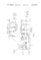
- FIG. 1 is a schematic view illustrating the sequence of steps in the process embodying this invention of in situ forming of a thermoplastic can end on a can body by a compression molding technique.
- FIG. 2 is a schematic top elevational view of an apparatus embodying this invention for forming and assembling a thermoplastic can end on a can body by compression molding, with the mandrels omitted where necessary for clarity.
- FIG. 3 is a sectional view taken on the plane 3--3 of FIG. 2.
- FIG. 4 is a sectional view taken on the plane 4--4 of FIG. 2.
- FIG. 5 is a sectional view taken on the plane 5--5 of FIG. 2.
- FIG. 5a is an enlarged scale view of the upper portion of the mechanism shown in FIG. 5.
- FIG. 5b is an enlarged scale view of the lower portion of the mechanism shown in FIG. 5.
- FIG. 6 is an enlarged scale, partial sectional view taken on the plane 6--6 of FIG. 2.
- FIG. 7 is an enlarged scale, partial sectional view taken on the plane 7--7 of FIG. 2.
- FIG. 7a is an enlarged scale sectional view taken on the plane 7a--7a of FIG. 7.
- FIG. 8 is an enlarged scale sectional view taken on the plane 8--8 of FIG. 2.
- FIG. 9 is an enlarged scale top elevational view of the infeed mechanism employed in the apparatus of FIG. 2.
- FIG. 10 is an enlarged scale, side elevational view of the mandrel conveyor chain.
- FIG. 11 is a schematic top elevational view of a modified form of apparatus for forming other types of plastic article by the compression molding technique.
- FIG. 12 is an enlarged scale, vertical sectional view taken on the plane 12--12 of FIG. 11.
- FIG. 13 is an enlarged scale, vertical sectional view taken on the plane 13--13 of FIG. 11.
- FIG. 14 is an enlarged scale vertical sectional view taken on the plane 14--14 of FIG. 11.
- each mold element 60 is elevated by a mechanism contained in the compression molding turret 50 to effect the compression molding of the thermoplastic gob between the bottom face of mandrel 10 and the mold element 60, thus forming the completed can end E around the bottom end portions of the can body C.
- the completed can body CE is then stripped from its carrying mandrel 10 and removed from the machine for further processing.
- Machine 1 has a conventional articulated frame structure formed by welding angle iron, channels and similar elements to provide the necessary mechanism supports.
- Previously formed fiber or plastic can side walls C are successively conveyed into the machine in an upright position by a horizontal conveyor 5. If the can side walls are fiber, they are provided with an outer and/or inner surface lamination of a plastic material that is thermally bondable to the material of gobs G.
- Conveyor 5 and worm 6 (FIG. 9) bring each successive can side wall C into engagement with the peripherally spaced pockets 30a of an infeed starwheel 30.
- Starwheel 30 in turn moves the can side walls C into a position respectively underlying the mandrels 10 and the vertically aligned mandrels 10 and can side walls C are moved around the periphery of a rotating mandrel assembly table 40.
- the can side walls C are elevated to fit snugly around the periphery of the mandrels 10, as best shown in FIGS. 3, 4 and 5b, with the bottom end portions of mandrel 10 spaced slightly inwardly from the lower end C1 of side wall C.
- the mandrels 10 with the can side walls C assembled thereto are then moved in a linear path 20a by the conveyor chain 20, then around the perpheries of a pair of guide sprockets 34 and 35, and are then carried around the circular perimeter of the compression molding turret 50 by engagement of conveyor chain 20 with sprocket teeth 51a and 51b (FIG. 5) formed on the turret 50.
- sprocket teeth 51a and 51b FIG. 5
- the female molding cavities 62a (FIGS. 1 and 5b) of such mold elements 60 are exposed to receive a gob G of heated thermoplastic material dropped from a suitable feeder indicated schematically by the shears F.
- a suitable feeder indicated schematically by the shears F.
- Each gob is of substantially the same quantity of material.
- a preferred feeder is described and illustrated in detail in the co-pending application of James W. Buckingham, Ser. No. 131,712, filed concurrently with this application, and of common ownership.
- the compression mold elements 60 are vertically elevated to surround the exposed bottom end C1 of the can wall C and enclose same in the molding cavity 100 defined between the end face of mandrel 10 and the co-operating mold element 60 (FIG. 6).
- the interposed gob G of plastic material is subjected to substantial pressures by the vertical closing movements of the mold element 60, and the thermoplastic material is distributed throughout the molding cavity 100 under significant pressures, generally on the order of at least 200 to 500 pounds per square inch, thereby producing the molding of a can bottom end E (FIG. 6) in attached relationship to the can side wall C.
- the compression molding is completed as the mandrels 10 and the co-operating mold elements 60 move around the perimeter of the compression molding turret 50. As they approach the end of their rotary path around the turret, the compression mold elements 60 are lowered to a position out of engagement with the overlying mandrels 10. Air cooling of molded can end wall E can then be initiated.
- the chain 20 carrying mandrels 10 is then trained around two idler sprocket elements 36 and 37 and then directed rearwardly toward the entry end of the machine along a horizontal linear path 20c.
- Path 20c of conveyor chain 20 carries the mandrels 10 with the completed can body CE above the conveyor 5 and around a disassembly table 70. Further air cooling of the molded can end E is accomplished along linear path 20c.
- pressured air is supplied to the hollow interior of each mandrel 10 sufficient to push off the completed can body C with the integrally molded can end E attached thereto (FIG. 8).
- the completed can body CE is then directed by suitable guides 75 onto the output end of the input conveyor 5 and removed from the machine 1 for further processing.
- All elements of the machine are driven from a single power source 15 through a gear reduction unit 15a and a primary drive sprocket 15b.
- a chain 16 connects the primary drive sprocket 15b to reduction sprocket 16b mounted on shaft 16a.
- a pair of sprockets 16c and 16d are driven by shaft 16a.
- Sprocket 16c is connected by chain 17 to a shaft 17a to drive small gear 17b which engages a large internal gear 50a to rotate the compression molding turret 50.
- Sprocket 16d is connected by a chain 18 to a gearing mechanism 18a which effects the synchronous operation of the gob feeder F.
- the conveyor chain 20 carrying the cylindrical mandrels 10 is engaged by suitable teeth 51a and 51b (FIG.
- Chain 20 is driven in exact synchronism with the rotational movement of the compression molding turret 50.
- Chain 20 is also employed to effect the driving of the disassembly table 70, the mandrel assembly table 40, by which the can side walls C are assembled on the mandrels 10, and the infeed starwheel 30.
- Infeed starwheel 30 is mounted on a vertical shaft 31 which in turn is keyed to sprocket 31a (FIG. 9) which drives a chain 32.
- Chain 32 drives an input sprocket 33a of a gear reduction mechanism 33 which effects the rotation of an input spacing worm 6 which is disposed adjacent to the input conveyor 5 to move the can side walls or bodies C into the pockets 30a of the infeed starwheel 30 in timed relationship.
- the mandrel conveyor chain 20 is shown as comprising two link type chains 21a and 21b disposed in spaced vertical alignment by bushings 22 mounted on common pivot pins 23 provided at spaced intervals along the length of the chain.
- the top portion of each pivot pin 23 is retained against downward vertical movements by snap ring 23a and the headed bottom portion 23b of the pin 23 extends in depending relationship a significant distance below the lowermost chain 21b to support a mandrel bushing 24 which in turn provides support for a mandrel assemblage 10 in depending relationship thereto.
- Two such pins 23 for each mandrel assemblage may be desirable.
- Bushing 24 has a radially projecting shoulder 24a at its lower end upon which the lower end of mandrel guide bushing 25 is supported.
- Bushing 25 in turn has a radially projecting shoulder 25a at its upper portion which provides vertical support to the mandrel assemblage 10 by engaging appropriately shaped guide rails provided on the various rotary tables and on the articulated frame of the machine 1, such as nylon rails 2 shown in FIG. 7.
- the particular guide rails shown in FIG. 5a constitute an inner circular rotating pocket rail 55 provided on the compression molding turret 50 and an outer annular rail 54d supported in surrounding radially spaced relationship to the inner guide rail 55 by the articulated frame structure of the machine 1.
- the mandrel 10 which is essentially of hollow tubular configuration is secured to the mandrel guide bushing 25 by a plurality of circumferentially spaced bolts 10a.
- Dowel pins 10b are provided to insure the vertical alignment of the mandrel 10 with the guide bushing 25.
- Intermediate guide bushing 25 and the top end of the mandrel 10 there is provided a circular plate 26 having an annular top shoulder 26a embracing the bottom end of guide bushing 25 and providing a top guide surface 26b for limiting any upward displacement of the mandrel assemblage 10, particularly during the compression molding operation.
- a lower annular flange 26c on circular plate 26 snugly surrounds the top end of mandrel 10 and provides a backing for a washer 27 which is press fitted to the top end portion of mandrel 10 and functions as a stop for the upward movement of a can body C applied to the mandrel 10.
- mold plate 12 (FIG. 5b and 7a) which is secured to the lower end of mandrel 10 by a plurality of peripherally spaced bolts 12a.
- Mold plate member 12 is provided with an upstanding annular flange or rib 12b which fits snugly within the interior of the hollow mandrel 10, snugly engaging the bore surface 10c thereof.
- the top surface of the annular rib 12b is closed by a cap 12k which is secured thereto by a plurality of peripherally spaced bolts 12m.
- a fluid pressure chamber 12e is thus defined.
- Cap 12k has a central bore 12n to receive the end of a plunger portion 14a of a valve 14 mounted in the central aperture 12c of the mold plate 12.
- Valve 14 has a conical head portion 14b which cooperates in sealing relationship with the correspondingly shaped end of the central aperture 12c.
- a spring 14d operates between the top surface of the valve plate 12 and a snap ring 14e provided on the stem portion 14a of plunger 14 to maintain a bias on such plunger to normally keep it in the closed position until an overriding air pressure is applied to chamber 12e.
- Suitable passages for applying air pressure to the chamber 12e defined between the cap 12k and the annular flange 12b are provided, such as the radial passage 25c in the guide bushing 25 (FIG. 5a) which communicates with an axially extending passage 25d, than an axially extending passage 26d provided in the bushing 26, then an axially extending passage 10d in mandrel 10 communicating with a radial passage 10e (FIGS. 5b and 7a) and thence through a radial passage 12f into the pressure chamber 12e.
- This arrangement of fluid passages permits the accomplishment of the removal of the completed can CE.
- a radial flange 12g defined on the outer side of the upstanding annular wall 12b of mold plate 12 provides a space for mounting an annular mold ring 13 whose peripheral surface 13a is displaced slightly outwardly beyond the peripheral surface of the remainder of the mandrel 10. Hence when a can side wall C is assembled on the mandrel 10, it will be snugly engaged by the peripheral surface 13a, but slightly spaced from peripheral surface 12h of the mold plate 12. Additionally, the lower outer corner 13b of mold ring 13 is bevelled and this provides the annular end wall of the molding cavity 100 (FIG. 6) which is defined between the lower end of each mandrel assemblage 10 and a co-operating mold element 60.
- a space 100a is thereby defined in the molding cavity 100 which includes the inner wall of end portions C 1 of can body wall C, thereby assuring that the molten plastic material forming the can end E is intimately engaged with the can body wall C.
- a detailed description of each molding element 60 will be hereinafter presented in the description of the rotary compression molding turret 50.
- the rotary table 40 accomplishes the application of successive can body walls C to successive mandrels 10.
- the mechanism for supplying the can body walls C to the rotary assembly table 40 includes the power driven worm feeder 6 and the input starwheel 30, both of which are of conventional construction and require no further description.
- the rotary mandrel loading table 40 will be seen as comprising a vertical shaft 41 which is appropriately journalled by the articulated frame of the machine 1.
- a can body transport table 42 is keyed to shaft 41 and is provided on its periphery with a plurality of generally semi-circular openings 42a within which a circular applicating plate 43 is mounted for reciprocating vertical movement.
- Each plate 43 has a depending bushing portion 43a mounted on a vertical plunger shaft 43b.
- a limited lost motion connection is provided between bushing 43a and shaft 43b by virtue of a set screw 43c traversing an axial slot 43d provided in the bushing 43a.
- a spring 43e effectively secures the sleeve applicating plate 43 to shaft 43b for upward vertical movement.
- Shaft 43b is journalled for axial vertical movement and moved around the drive shaft 41 by a bushing 44 which is mounted between two drive plates 44a and 44b, both of which are keyed to shaft 41 for co-rotation.
- the outer periphery of plate 44b carries an annular depending guide sleeve 44c, which is provided with a plurality of vertically extending slots 44d which respectively receive rollers 43f suitably secured to the lower end of the shaft 43b to insure that the shaft moves in a vertical plane.
- each plate 43 is provided with a substantially semi-circular upstanding side wall 43k to stop the incoming movement of the can side wall C in a position concentric with the axis of plunger shaft 43b. Additionally, a star wheel 47 affixed to shaft 41 provides further support to can bodies C.
- the mandrels 10 are brought into successive overhead alignment with the applicating plates 43 by the engagement of the links 21a and 21b of the mandrel conveying chain 20 with the teeth of two sprockets 46a and 46b respectively secured to the top portions of center shaft 41.
- the interengagement of the conveyor chain 20 with such sprockets imparts the rotational driving movement to the shaft 41 and hence operates the entire assembly table 40 in synchronism with the movements of the mandrels 10 around the periphery of the table.
- the assembly table 40 is provided with a positioning ring 48 secured in depending relationship to sprocket 46b and having semi-circular pockets 48a engaging mandrel bushing 25a of mandrel 10.
- Sleeves 41a, 41b, 41c and 41d on center shaft 41 provide spacing and vertical support for the various rotating tables.
- the cam track 45a effects the elevation of shaft 43b and hence raises the applicating plate 43, carrying with it the can body wall C and forces the can body wall C around the external surfaces of the mandrel 10 until the top edges of the body wall C engage the stop ring 27.
- the spring 43e provided between shaft 43b and applicating plate 43 absorbs any such oversize dimension without imparting any injury to the particular can side wall C.
- each mandrel 10 leaves the assembly station 40 on the conveyor chain 20, it will carry therewith a can side wall body C snugly engaged on the mandrel 10 by virtue of its frictional engagement with the protruding ring 13 provided on the bottom portions of mandrel 10.
- the required rotational movement of the rotary compression molding turret 50 is imparted by the pinion 17b engaging internal ring gear 50a carried by rotary table 52 which is welded or keyed to a central vertical shaft 53, which is suitably journalled on the articulated framework of the machine 1. Because the individual mandrel assemblages 10 are subjected to a very substantial upward force during the compression molding operation, which is accomplished in a portion of the path of such mandrels around the compression molding turret 50, a comprehensive reinforcing mechanism to resist such upward force is provided.
- the sprockets 51a and 51b which drive chain links 21a and 21b of mandrel conveyor chain 20, are interconnected by a rigid annular ring 51c and the top sprocket 51a has an additional annular ring 51d secured thereto.
- Sprockets 51a and 51b are keyed or welded to control shaft 53.
- Ring 51d bears against the peripheries of a plurality of thrust rollers 54 which are respectively journalled in a circumferentally spaced array of depending brackets 54a which are in turn rigidly secured to a massive overhead horizontal beam elements 1d of the articulated frame structure of the machine 1.
- annular support ring 54c is secured to horizontal frame elements 1d in depending relationship and supports an annular guide block or rail 54d which is secured to the bottom end of ring 54c by bolts 54e.
- the inner surface 54f of the guide block 54d snugly conforms to the outer periphery of the mounting bushing flange 25a provided on each mandrel assemblage 10.
- the inner periphery of the mounting bushing flange 25a is supported by semi-circular pockets provided on the periphery of rotating circular pocket rail 55, and an annular reinforcing ring 54g is mounted between the top surface of rotating pocket rail 55 and the bottom surface of pinion 51b.
- the circular molding table 52 is mounted on the lower portions of shaft 53 for co-rotation.
- Molding table 52 provided with a plurality of circumferentially spaced apertures 52a which respectively receive reduced diameter end portion 61c of molding element 60.
- the spacing of the molding elements 60 corresponds, of course, to the circumferential spacing of the mandrels 10, so that each molding element 50 is vertically and co-axially aligned with a molding element 10 moving around the periphery of the compression molding turret 50.
- Each molding element 60 (FIG. 5b) comprises an outer housing defined by a sleeve 61 which is secured by peripherally spaced bolts 61a and dowels to an annular base 61b having an axially extending stem portion 61c projecting through the openings 52a provided in the table 52.
- Bolts 52b secure each housing 61 to the table 52, and dowel pins 53b assure the alignment.
- the female half of a compression mold mechanism 62 is slidably mounted for vertical movements relative to the table 52, hence relative to the overlying mandrel 10.
- a stop ring 61e is secured by bolts 61f to the top of sleeve portion 61. Ring 61e has its inner periphery overlying the bore 61d and hence functions as a stop for the upward movement of a portion of the female mold mechanism 62.
- Mold mechanism 62 constitutes an assemblage of three vertically spaced annular elements 80, 84 and 88, which are movable vertically in a desired sequence by a vertically shiftable shaft 63.
- the annular element 80 has a top surface 80a that forms the bottom portions of the molding cavity 100 when the female mold mechanism 62 is disposed in closed relationship with respect to the mandrel 10.
- Annular element 80 is rigidly secured to the top end of a vertical actuation shaft 63 by an axially disposed elongated hollow bolt 62a, which threadably engages the top end of a bolt 62b, which is suitably secured within the lower portions of the hollow bore of the actuating shaft 63.
- a key 62c engages bolt 62a, annular element 80, and shaft 63. It is therefore apparent that the annular molding cavity base element 80 is movable directly with the actuating shaft 63.
- the lower annular element 88 is also vertically co-movable with actuating shaft 63, resting on top of a bearing sleeve 63a which is suitably secured to shaft 63 for co-movement.
- Sleeve 63a in turn is suitably journalled for vertical movements in the hollow stem portion 61c of mold housing 61.
- the intermediate annular element 84 freely surrounds actuating shaft 63 and is supported and disposed in spaced relationship above lower annular element 88 by a plurality of peripherally spaced, heavy compression springs 84a.
- the top face of intermediate annular element 84 is spaced slightly below the bottom face of the mold base annular element 80 and abuts the lower face of a ring 80d that is peripherally secured to the mold base element 80 by bolts 30e and cooperates with an annular recess in the bottom face of mold base element 80 to define a cooling channel 80c therein.
- the side walls of the molding cavity 100 are defined by a plurality of annular mold wall segments 66 which are mounted on an annular segment support wall 85.
- Support wall 85 is in turn supported in slightly spaced relationship above the intermediate annular element 84 by a plurality of peripherally disposed, relatively light compression springs 84c.
- Annular wall 85 has a radially enlarged portion 85a which slidably cooperates with the interior cylindrical wall 61d of the housing 61 and provides a radial shoulder abutting the stop shoulder 61g provided on the stop ring 61e.
- the segment supporting wall 85 has a segment retaining ring 85b peripherally secured above its top surface by a plurality of bolts 85c.
- a plurality of spacer washers 85d maintains space between supporting wall 85 and segment retaining ring 85b to allow for sliding movement of segments 66.
- Radial slots 66b in segments 66 surround spacer washers 85d to allow radial movement of segments 66 without interference from spacer washers 85d.
- the inner periphery of ring 85b overlies the top surfaces of the segments 66 and holds such segments in assembly.
- Annular mold wall segments 66 have vertically inclined bottom surfaces 66a engaged by inclined top surface 81a of a vertically shiftable actuating sleeve 81.
- Sleeve 81 is in turn secured by bolts 84b to intermediate annular element 84.
- Compression springs 66d urge segments 66 outwardly.
- the compression molding operation is completed by still further upward movement of actuating shaft 63 which, when the periphery of the intermediate annular element 84 engages the vertically locked bottom surface of the segment retaining wall 85 now effects the compression of the heavy compression springs 84a provided between the bottom annular element 88 and the intermediate annular element 84.
- Dowel pins 88b prevent relative reotation of annular elements 88 and 84.
- the gob G of thermoplastic material disposed within the molding cavity 100 is now being compressed between the bottom face 12g of the mold base element 12 on mandrel 10 and the upper face 80a of the annular molding base element 80.
- the rate of upward movement of the actuating shaft 63 is selected so as to produce a substantial compression force upon the gob G throughout the compression molding operation.
- a compression molding force on the order of at least 200 to 500 pounds per square inch is exerted upon the thermoplastic material throughout all portions of the compression molding operation, but particularly, at the end of the compression molding operation when the thermoplastic material has been forced radially outwardly into intimate engagement with both sides of the can side wall portion C1 that projects into the molding cavity 100.
- shaft 63 is provided at its lower end with a depending roller 63b (FIG. 5) journalled on a diametrical pin 63c and engageable with the upper surface 64a of an annular cam track 64 which is rigidly secured to the bottom articulated frame elements 1a of the machine 1.
- a depending roller 63b (FIG. 5) journalled on a diametrical pin 63c and engageable with the upper surface 64a of an annular cam track 64 which is rigidly secured to the bottom articulated frame elements 1a of the machine 1.
- the limit to the upward movement of the female mold mechanism 62 is determined by the engagement of the top surface of the lower annular element 88 with the bottom surface of the intermediate annular element 84 which, as previously mentioned, is stopped in its upward travel by engagement with the segment retaining sidewall 85 which in turn is stopped by the stop ring 61e.
- a precise limit to the upward movement of the female molding mechanism 62 relative to the plunger 10 is provided, thereby assuring that the vertical dimensions of the molding cavity 100 will be precisely duplicated for each successive engagement of the mandrels 10 with the female molding mechanisms 62.
- the mandrels 10 are not in overlying relationship with the molding element 60 around the entire periphery of the rotary compression molding turret 50. There is an arcuate space where the mandrels 10 are not overlying the molding elements 60 and this gap is utilized to effect the feeding of a gob G of molten thermoplastic material onto the top mold face 80a of each successive mold unit 60.
- the gob G has been deposited by the gob feeder F, (FIG. 1) the continued rotation of the mold table 52 brings the molding unit 60, with the gob G resting thereon, into vertical alignment with one of the overlying mandrels 10.
- the cam track 64a is designed to immediately thereafter raise the shaft 63, hence the molding mechanism 62, to its extreme upper position determined by the stop ring 61e and thus define the molding cavity 100 between the mold face 80a.
- Molding mechanisms 62 are maintained in their raised molding positions by cam track 64a until it is assured that sufficient cooling of the compression molded plastic has been accomplished so that the plastic will maintain a self-supporting configuration.
- Such cooling may be expedited through the circulation of water or other cooling fluid through cooling passage 80c provided in the base element 80, connecting passages 63d provided in actuating shaft 63, and a conventional fluid connection provided by piping 65 to an appropriate source of cooling fluid.
- cooling passage 80c provided in the base element 80
- connecting passages 63d provided in actuating shaft 63
- a conventional fluid connection provided by piping 65 to an appropriate source of cooling fluid.
- the initial lowering movement of the actuating shaft 63 produces an immediate downward displacement of the upper mold base annular element 80. It does not, however, result in a concurrent downward movement of the mold wall segments 66, because this would effect a stripping action on the thermoplastic material that has flowed into those portions into the molding cavity 100 which underlie the bottom portions of the segments 66.
- the segment supporting wall 85 carrying the segment 66 does not move downwardly until after the release of the compression forces on the springs 84c, and this is accomplished by the downward movement of the actuating sleeve 81 which occurs upon the release of the compression forces in the heavy compression springs 84a.
- the mandrel 10, carrying the can body wall C and the end wall E molded thereto may be moved by the conveyor chain 20 from its position of vertical alignment with the mold unit 60 and proceed to enter the linear path 20c of the conveyor chain 20.
- the chain links 21a and 21b of conveyor 20 respectively engage sprockets 71a and 71b (FIG. 8) which are in turn rigidly secured to a vertical shaft 71 which is suitably journalled for rotation in the articulated frame elements of the machine 1.
- sprockets 71a and 71b (FIG. 8) which are in turn rigidly secured to a vertical shaft 71 which is suitably journalled for rotation in the articulated frame elements of the machine 1.
- Passage 72a is connected to a source 76 of relatively high pressure air by piping 76a and this pressured fluid effects the downward stripping of the completed can body CE from the mandrel 10.
- the body CE is thus deposited on a rotary table 73 carried by shaft 71.
- Upstanding arcuate guides 74 are mounted above table 73 to prevent the inadvertent toppling of the completed can bodies CE.
- the completed can bodies CE are then engaged by stationary guides 75 and moved by their own pressure against each other, produced by the forwarding movement of the rotary table 73, onto the output end of the conveyor 5, which then conveys the completed can bodies CE either to machines for performing further operations or to a packing machine.
- the empty mandrels 10 are then carried by the conveyor chain 20 back to the assembly table 30 where new can bodies C are applied to the mandrels and the operations heretofore described are repeated.
- FIGS. 11-14 wherein similar numerals refer to similar mechanisms heretofore described, it will be seen that it is only necessary to eliminate the can body feeding mechanism 30, and the mandrel loading mechanism 40 from the previously described machine and the end result is a machine that is capable of molding individual plastic articles as defined by the configuration of the mold cavity. Of course, these mechanisms can remain intact and no can bodies C be fed into the machine.
- the machine shown in FIGS. 11-14 is designed solely to produce individual articles. Obviously, the mandrels 10 should now more properly be called plungers.
- the mold cavity 101 defined between the bottom end of each plunger 10 and the cooperating molding element 60 would, of course, be constructed to conform to the shape of the desired plastic article, here shown as a plastic snap cap SC. Otherwise, the operation of the machine would be the same except that the plungers 10 proceed from disassembly table 70 around a guide pulley 80 directly to the compression molding turret 50 without having any can body or similar article assembled thereto. As shown in FIG.
- the desired article SC is compression molded from a gob of molten thermoplastic material at the compression molding turret 50, following which the mold elements 60 are dropped vertically with respect to the plungers 10 and the plungers 10 proceed to the unloading table 70 (FIG. 13) carrying the molded articles SC thereon. This presumes that the molding article is of such configuration that it would adhere to the plunger.
- the molded particle SC is blown off plunger 10 at the unloading table 70 (FIG. 14) and deposited on the conveyor 5.
Abstract
Description
Claims (12)
Priority Applications (1)
| Application Number | Priority Date | Filing Date | Title |
|---|---|---|---|
| US06/131,713 US4314799A (en) | 1980-03-19 | 1980-03-19 | Compression molding machine for organic thermoplastic materials |
Applications Claiming Priority (1)
| Application Number | Priority Date | Filing Date | Title |
|---|---|---|---|
| US06/131,713 US4314799A (en) | 1980-03-19 | 1980-03-19 | Compression molding machine for organic thermoplastic materials |
Publications (1)
| Publication Number | Publication Date |
|---|---|
| US4314799A true US4314799A (en) | 1982-02-09 |
Family
ID=22450682
Family Applications (1)
| Application Number | Title | Priority Date | Filing Date |
|---|---|---|---|
| US06/131,713 Expired - Lifetime US4314799A (en) | 1980-03-19 | 1980-03-19 | Compression molding machine for organic thermoplastic materials |
Country Status (1)
| Country | Link |
|---|---|
| US (1) | US4314799A (en) |
Cited By (16)
| Publication number | Priority date | Publication date | Assignee | Title |
|---|---|---|---|---|
| EP0175642A2 (en) * | 1984-09-18 | 1986-03-26 | H. Obrist & Co. AG | Method and apparatus for producing a moulded plastics article |
| EP0195136A1 (en) * | 1985-03-18 | 1986-09-24 | Coenrardus Hubertus Aquarius | Process for the manufacture of lollipops, a device to be used for this purpose and the product obtained from this process |
| EP0595587A1 (en) * | 1992-10-30 | 1994-05-04 | Impact International Pty. Ltd. | Method and apparatus for forming a base on a tubular container |
| EP0705673A2 (en) | 1994-09-26 | 1996-04-10 | Becton, Dickinson and Company | Medical articles and method therefor |
| US5554327A (en) * | 1993-10-14 | 1996-09-10 | Owens-Illinois Closure Inc. | Method and apparatus for compression molding plastic articles |
| US5670100A (en) * | 1993-10-14 | 1997-09-23 | Owens-Illinois Closure Inc. | Method and apparatus for compression molding plastic articles |
| EP0909535A2 (en) * | 1997-09-26 | 1999-04-21 | Gebr. Bindler Maschinenfabrik GmbH & Co. KG | Fabrication process for shaped chocolate articles |
| US5932155A (en) * | 1993-10-14 | 1999-08-03 | Owens-Illinois Closure Inc. | Method and apparatus for providing overload protection in compression molding machines |
| US5961911A (en) * | 1997-12-05 | 1999-10-05 | Becton Dickinson And Company | Process for manufacture of closure assembly |
| WO2002074523A1 (en) * | 2001-03-19 | 2002-09-26 | Cebal S.A.S. | Plant for production of flexible tubes made from plastic with moulding of the head on top of the skirt carried out by continuously moving tools |
| US20040061256A1 (en) * | 2001-02-26 | 2004-04-01 | Michel Bosshardt | Method for producing plastic assembly parts |
| US20040060894A1 (en) * | 2001-01-18 | 2004-04-01 | Fiorenzo Parrinello | Method for creating a seal gasket at the top of a container closure cap, and a cap comprising said gasket |
| US20050051928A1 (en) * | 2002-03-18 | 2005-03-10 | Bertrand Gruau | Method of producing a compression-moulded plastic part comprising a neck which is equipped with a dispensing orifice |
| US20070134361A1 (en) * | 2004-04-08 | 2007-06-14 | Graham Packaging Pet Technologies Inc. | Pellet transfer apparatus and method |
| US20080029922A1 (en) * | 2006-05-18 | 2008-02-07 | Tapco International Corporation | Polymer molding system and method of operation for producing an article of manufacture |
| JP2022502289A (en) * | 2018-10-11 | 2022-01-11 | サチミ、コオペラティバ、メッカニーチ、イモラ、ソチエタ、コオペラティバSacmi Cooperativa Meccanici Imola Societa’ Cooperativa | Equipment for compression molding concave objects |
Citations (2)
| Publication number | Priority date | Publication date | Assignee | Title |
|---|---|---|---|---|
| US2607080A (en) * | 1947-03-15 | 1952-08-19 | John H F Stewart | Mold for producing plastic articles without flash |
| US3158898A (en) * | 1961-03-13 | 1964-12-01 | Dow Chemical Co | Apparatus for molding plastic containers |
-
1980
- 1980-03-19 US US06/131,713 patent/US4314799A/en not_active Expired - Lifetime
Patent Citations (2)
| Publication number | Priority date | Publication date | Assignee | Title |
|---|---|---|---|---|
| US2607080A (en) * | 1947-03-15 | 1952-08-19 | John H F Stewart | Mold for producing plastic articles without flash |
| US3158898A (en) * | 1961-03-13 | 1964-12-01 | Dow Chemical Co | Apparatus for molding plastic containers |
Cited By (31)
| Publication number | Priority date | Publication date | Assignee | Title |
|---|---|---|---|---|
| EP0175642B1 (en) * | 1984-09-18 | 1990-10-10 | H. Obrist & Co. AG | Method and apparatus for producing a moulded plastics article |
| EP0175642A2 (en) * | 1984-09-18 | 1986-03-26 | H. Obrist & Co. AG | Method and apparatus for producing a moulded plastics article |
| EP0195136A1 (en) * | 1985-03-18 | 1986-09-24 | Coenrardus Hubertus Aquarius | Process for the manufacture of lollipops, a device to be used for this purpose and the product obtained from this process |
| EP0197222A1 (en) * | 1985-03-18 | 1986-10-15 | Bernat Fontlladosa, Enrique | Improvements in lollipops and their manufacture |
| EP0595587A1 (en) * | 1992-10-30 | 1994-05-04 | Impact International Pty. Ltd. | Method and apparatus for forming a base on a tubular container |
| US5770130A (en) * | 1993-10-14 | 1998-06-23 | Owens-Illinois Closure Inc. | Method and apparatus for compression molding plastic articles |
| US5989007A (en) * | 1993-10-14 | 1999-11-23 | Owens-Illinois Closure Inc. | Method and apparatus for compression molding plastic articles |
| US5554327A (en) * | 1993-10-14 | 1996-09-10 | Owens-Illinois Closure Inc. | Method and apparatus for compression molding plastic articles |
| US5670100A (en) * | 1993-10-14 | 1997-09-23 | Owens-Illinois Closure Inc. | Method and apparatus for compression molding plastic articles |
| US5932155A (en) * | 1993-10-14 | 1999-08-03 | Owens-Illinois Closure Inc. | Method and apparatus for providing overload protection in compression molding machines |
| EP0705673A3 (en) * | 1994-09-26 | 1997-05-07 | Becton Dickinson Co | Medical articles and method therefor |
| US5744087A (en) * | 1994-09-26 | 1998-04-28 | Becton, Dickinson And Company | Medical articles and method therefor |
| EP0705673A2 (en) | 1994-09-26 | 1996-04-10 | Becton, Dickinson and Company | Medical articles and method therefor |
| EP0909535A3 (en) * | 1997-09-26 | 2000-05-31 | Gebr. Bindler Maschinenfabrik GmbH & Co. KG | Fabrication process for shaped chocolate articles |
| EP0909535A2 (en) * | 1997-09-26 | 1999-04-21 | Gebr. Bindler Maschinenfabrik GmbH & Co. KG | Fabrication process for shaped chocolate articles |
| US5961911A (en) * | 1997-12-05 | 1999-10-05 | Becton Dickinson And Company | Process for manufacture of closure assembly |
| US8640898B2 (en) | 2001-01-18 | 2014-02-04 | Sacmi-Cooperativa Meccanici Imola-Soc. Coop A.R.L. | Closure cap comprising a seal gasket |
| US20040060894A1 (en) * | 2001-01-18 | 2004-04-01 | Fiorenzo Parrinello | Method for creating a seal gasket at the top of a container closure cap, and a cap comprising said gasket |
| US20080105685A1 (en) * | 2001-01-18 | 2008-05-08 | Sacmi-Cooperativa Meccanici Imola-Soc.Coop. A.R.L. | Method for creating a seal gasket at the top of a container closure cap, and a cap comprising said gasket |
| US7022277B2 (en) * | 2001-02-26 | 2006-04-04 | Cebal S.A.S | Method for producing plastic assembly parts |
| US20040061256A1 (en) * | 2001-02-26 | 2004-04-01 | Michel Bosshardt | Method for producing plastic assembly parts |
| WO2002074523A1 (en) * | 2001-03-19 | 2002-09-26 | Cebal S.A.S. | Plant for production of flexible tubes made from plastic with moulding of the head on top of the skirt carried out by continuously moving tools |
| US7037456B2 (en) | 2001-03-19 | 2006-05-02 | Cebal Sa | Manufacturing apparatus for flexible plastic tubes |
| US20020175445A1 (en) * | 2001-03-19 | 2002-11-28 | Cebal Sa | Manufacturing apparatus for flexible plastic tubes |
| US20050051928A1 (en) * | 2002-03-18 | 2005-03-10 | Bertrand Gruau | Method of producing a compression-moulded plastic part comprising a neck which is equipped with a dispensing orifice |
| US8025825B2 (en) * | 2002-03-18 | 2011-09-27 | Cebal Sas | Method of producing a compression-moulded plastic part comprising a neck which is equipped with a dispensing orifice |
| US20070134361A1 (en) * | 2004-04-08 | 2007-06-14 | Graham Packaging Pet Technologies Inc. | Pellet transfer apparatus and method |
| US7442027B2 (en) * | 2004-04-08 | 2008-10-28 | Graham Packaging Pet Technologies Inc. | Pellet transfer apparatus and method |
| US20090087508A1 (en) * | 2004-04-08 | 2009-04-02 | Graham Packaging Pet Technologies Inc. | Pellet transfer appratus and method |
| US20080029922A1 (en) * | 2006-05-18 | 2008-02-07 | Tapco International Corporation | Polymer molding system and method of operation for producing an article of manufacture |
| JP2022502289A (en) * | 2018-10-11 | 2022-01-11 | サチミ、コオペラティバ、メッカニーチ、イモラ、ソチエタ、コオペラティバSacmi Cooperativa Meccanici Imola Societa’ Cooperativa | Equipment for compression molding concave objects |
Similar Documents
| Publication | Publication Date | Title |
|---|---|---|
| US4314799A (en) | Compression molding machine for organic thermoplastic materials | |
| US4801260A (en) | Rotary blow molding machine | |
| US6976836B2 (en) | Biaxial stretch blow molding method and apparatus for wide-mouthed containers | |
| US3843286A (en) | Blow molding apparatus | |
| US4861542A (en) | Rotary blow molding method | |
| JPS6145524B2 (en) | ||
| AU593496B2 (en) | Take-out assembly for blow molding machine | |
| EP0162458B1 (en) | Temperature control blow molding equipment in injection stretch blow molding machine | |
| KR870000155A (en) | Apparatus and method for molding plastic liner and placing in closure | |
| US4741688A (en) | Injection stretching and blow molding machine | |
| JP3130140B2 (en) | Injection stretch blow molding method and apparatus | |
| US3555598A (en) | Apparatus for blow molding of plastic articles | |
| CA1101172A (en) | Forging and thermoforming hollow thermoplastic biaxially oriented articles | |
| GB1391237A (en) | Blow moulding apparatus | |
| US4439127A (en) | Machine for producing blown hollow synthetic resin workpieces | |
| AU597803B2 (en) | Rotary blow molding machine | |
| US3947180A (en) | Apparatus for combined injection moulding and blow forming of containers or objects form plastics material | |
| US6060012A (en) | Method for blow-molding and releasing hollow articles | |
| CN100522534C (en) | Tire vulcanizing method and vulcanizer for performing the method | |
| US3146491A (en) | Production of hollow articles in thermoplastic material | |
| US3491404A (en) | Blow molding apparatus | |
| CN209903902U (en) | Bottle blowing machine | |
| US4560341A (en) | Apparatus for transporting sectional molds | |
| US3767345A (en) | Double parison die head control mechanism | |
| JPH1148323A (en) | Method and apparatus for biaxially orientating blow molding method |
Legal Events
| Date | Code | Title | Description |
|---|---|---|---|
| AS | Assignment |
Owner name: OWENS-ILLINOIS, INC. A CORP. OF OH Free format text: ASSIGNMENT OF ASSIGNORS INTEREST.;ASSIGNORS:AMBERG, STEPHEN W.;AMBERG, RALPH G.;REEL/FRAME:003920/0963;SIGNING DATES FROM 19800305 TO 19800310 Owner name: OWENS-ILLINOIS, INC., OHIO Free format text: ASSIGNMENT OF ASSIGNORS INTEREST;ASSIGNORS:AMBERG, STEPHEN W.;AMBERG, RALPH G.;SIGNING DATES FROM 19800305 TO 19800310;REEL/FRAME:003920/0963 |
|
| STCF | Information on status: patent grant |
Free format text: PATENTED CASE |
|
| AS | Assignment |
Owner name: OWENS-ILLINOIS PLASTIC PRODUCTS INC., ONE SEAGATE, Free format text: ASSIGNMENT OF ASSIGNORS INTEREST. EFFECTIVE APRIL 15, 1987;ASSIGNOR:OWENS-ILLINOIS, INC.;REEL/FRAME:004875/0962 Effective date: 19870323 Owner name: OWENS-ILLINOIS PLASTIC PRODUCTS INC., A CORP. OF D Free format text: ASSIGNMENT OF ASSIGNORS INTEREST;ASSIGNOR:OWENS-ILLINOIS, INC.;REEL/FRAME:004875/0962 Effective date: 19870323 |