US4350453A - Cartridge for correction media or tacky tape with a wrap spring - Google Patents
Cartridge for correction media or tacky tape with a wrap spring Download PDFInfo
- Publication number
- US4350453A US4350453A US06/165,827 US16582780A US4350453A US 4350453 A US4350453 A US 4350453A US 16582780 A US16582780 A US 16582780A US 4350453 A US4350453 A US 4350453A
- Authority
- US
- United States
- Prior art keywords
- cartridge
- web
- tape
- beam spring
- spring means
- Prior art date
- Legal status (The legal status is an assumption and is not a legal conclusion. Google has not performed a legal analysis and makes no representation as to the accuracy of the status listed.)
- Expired - Lifetime
Links
Images

Classifications
-
- B—PERFORMING OPERATIONS; TRANSPORTING
- B41—PRINTING; LINING MACHINES; TYPEWRITERS; STAMPS
- B41J—TYPEWRITERS; SELECTIVE PRINTING MECHANISMS, i.e. MECHANISMS PRINTING OTHERWISE THAN FROM A FORME; CORRECTION OF TYPOGRAPHICAL ERRORS
- B41J32/00—Ink-ribbon cartridges
Definitions
- Correcting typewriters utilizing adhesive correction media have been available in significant numbers since 1973 in the commercial marketplace.
- the previous correction tape constituted a reel to reel arrangement where each reel, takeup and supply were separate and independent and not commonly supported.
- correction tapes One complicating factor when dealing with correction tapes generally not found when dealing with such things as film ribbons and fabric ribbons is that film and fabric ribbons will slip with respect to each other in a particular convolution while the tacky surface of the correction tape does not readily slip in the same manner.
- This non-slip nature of the correction tape resists normal smoothing of the takeup convolutions as may be accomplished with ribbons by tension. Therefore, once the material has become adhered to the adjacent backing, it is virtually impossible to cause a slipping by means of tension only.
- any wrinkle inadvertently formed will propogate throughout the remainder of the radius of the takeup spool with additional convolutions.
- Tensioning devices have been disclosed in the past which engage the periphery of ribbon spools.
- the most pertinent example of a tensioning device engaging the periphery of a takeup spool is found in U.S. Pat. No. 4,013,160.
- a second version of that device is illustrated in U.S. Pat. No. 4,147,439.
- the ends of the spring member which constitutes a drag force on the supply spool has a second end engaged with the periphery of the takeup spool for purposes of forming a bias force between the two spools.
- the patents indicate that the function and purpose is that of providing a tension to the web and that a relatively high friction surface material is attached to the arm engaged with the supply spool to that end.
- the braking surface is formed such that if a bulge is present, the action of the bulge against the brake will cause the brake to cam out and allow passage of the bulge.
- This device although providing the desired tension, does not appear to have any beneficial effect as far as maintaining a well ordered takeup spool inasmuch as the ribbon being transmitted will slip with respect to the next convolution and, therefore, does not present the problem encountered in the takeup spool portion of the correction tape cartridge disclosed in this application.
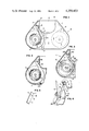
- FIG. 1 illustrates a printer ribbon cartridge with the takeup spool exposed and the spring in wiping relationship with the outer convolution of the takeup spool.
- FIG. 2 illustrates the type of voids which will typically form without the use of some member to insure proper engagement with the periphery of the takeup spool and tape disc.
- FIG. 3 illustrates a mode of operation wherein the wiper spring may contact the periphery of the takeup spool prematurely.
- FIG. 4 illustrates the spring of FIG. 1 showing a relieved cross sectional portion of FIG. 4.
- FIG. 5 illustrates an alternative embodiment of the relieved cross section of the spring illustrated in FIG. 4.
- FIG. 6 illustrates the relieved cross section spring on a substantially full takeup spool.
- FIG. 7 illustrates an alternate spring biasing approach.
- FIG. 1 illustrates a printer or typewriter ribbon cartridge 10 having a supply spool 12 of correction tape 16 and a tensioning wire 14 engaging the back surface of tape 16.
- Tape 16 will exit from the chamber of cartridge 10 at exit port 18.
- the chamber of cartridge 10 is formed by a top wall 20, a bottom wall 22 and side walls 24.
- Tape 16 extends across the front portion of cartridge 10 and reenters the cartridge 10 at reentry port 26.
- the tape 16 is passed around guide post 28 to prevent the tape 16 from wrapping too sharply along the wall 24 which partially forms reentry port 26.
- correction tape 16 passes the guide post 28, it is then pulled in a straight line to a position on the tangent of the takeup spool 30 having flange 32 thereon.
- the tacky or sticky surface of the tape 16 will engage the previously wound convolution.
- the tape 16 may contact the disc 34 slightly prior to the tangent point between tape 16 and disc 34 and possibly form a small buckle or bubble type discontinuity in the cylindrical exterior.
- Spring member 40 is comprised of a main beam portion, a grounding segment 42 and a wiping portion 44.
- the wiping portion 44 and spring member 40 are joined at a bend 46 which allows the orientation of wiping portion 44 at an angle with respect to both the surface of disc 34 and spring member 40.
- the wiping action of the edge of wiping portion 44 relatively firmly places the adhesive surface of tape 16 into engagement with the outer wrap of disc 34 and it is believed that it effectively squeeges the buckle until such time as the lightly adhesive engagement of tape 16 and the disc 34 upstream from the wiping portion 44 breaks away due to tension, thus insuring the prevention of the buckle or bubble such as is seen at 36 in FIG. 2.
- the wiping edge of wiping portion 44 insures a smooth engagement of tape 16 with disc 34.
- a further improvement is shown in FIG. 1 and FIG. 4 with a second embodiment in FIG. 5.
- Spring member 40 may have a relieved portion 50 intermediate a pair of notches 52 or 54.
- Notches 52 take the shape of semi-circular portions being removed from spring member 40 between the main portion of the spring member 40 and the grounding segment 42.
- FIG. 5 illustrates the use of triangular punched notches 54 to accomplish the same relieving of the relieved portion 50.
- Cartridge 10 in FIG. 3 is illustrated as it has approached and arrived at completion of usage.
- the capacity of the cartridge 10 may be increased to accommodate additional tape 16 by implementing one of the embodiments illustrated in FIG. 4 or 5.
- FIG. 3 illustrates an embodiment wherein the quantity of tape 16 does not exceed the flex capability of spring member 40.
- the engagement of tape 16 with the outer convolutions of disc 34 at a point other than the point of engagement between wiping portion 44 and disc 34 may potentially permit surface irregularities to form.
- the main beam portion 40 With the concentration of the flexure at the relieved portion 50, the main beam portion 40 is permitted to maintain a larger radius or a flatter configuration, thus insuring that the wiping portion 44 will engage the periphery of tape disc 34 in the desired manner to an increased diameter of disc 34.
- relieved portion 50 of the spring member 40 would include rectangular notching and a coining operation whereby the coining dye will deform the spring member 40 to make relieved portion 50 thinner.
- Bend 46 is of a sufficient angle as to cause wiping portion 44 to engage the disc 34 in a wiping action at all orientations.
- a rigid wiper member 60 or a spring 60 of less flexibility than those of FIGS. 1-6 is illustrated.
- the bias is provided by compression spring 62 against stop 64.
- Spring 60 is formed with a retaining bulge 66 on the end which pivots between posts 68 and abutment 70 which also serves as a ribbon guide.
Abstract
A typewriter correction tape cartridge for holding and feeding correction tape for a correcting typewriter is improved by the addition of a beam spring cantilever supported such that one end of the beam spring wipes the correction tape onto the takeup spool. This will act to eliminate bubbles, wrinkles and crimps in the tape as it is placed in a new convolution on the spool and will thus reduce the outside diameter of the ultimate disc of used tape. The advantage of this spring is that a reduced size cartridge may be used while utilizing the entire volume of tape supplied on the supply side of the cartridge and, secondly, a more reliable takeup is accomplished due to the elimination of irregularities in the takeup disc. Where space considerations dictate that the spring be bent back sufficiently to accommodate a full spool without contacting the disc of ribbon accumulated on the takeup spool, the cross section of the spring, at a point near the anchor point, may be reduced by notching to provide a stress concentrated flex point and allow the spring member to still perform its function without premature engagement with the disc at a point other than at the wiper end.
Description
Correcting typewriters utilizing adhesive correction media have been available in significant numbers since 1973 in the commercial marketplace. The previous correction tape constituted a reel to reel arrangement where each reel, takeup and supply were separate and independent and not commonly supported.
With the increased usage of ribbons in cartridges, it has become desirable to include the correction tape in a cartridge for ease in handling and ease in installation. By including the correction tape in the cartridge, it is also considerably easier to design a ribbon and correction tape feed mechanism to accommodate the cartridge than to have to accommodate a ribbon cartridge and separate and loose correction tape spools. With the inclusion of the correction tape within a correction tape cartridge, the physical volume occupied by the completely filled takeup spool becomes a consideration and, in many cases, a limiting consideration as to the quantity of tape that may be originally placed in the cartridge and the ability to consume all of the correction tape supplied.
One complicating factor when dealing with correction tapes generally not found when dealing with such things as film ribbons and fabric ribbons is that film and fabric ribbons will slip with respect to each other in a particular convolution while the tacky surface of the correction tape does not readily slip in the same manner. This non-slip nature of the correction tape resists normal smoothing of the takeup convolutions as may be accomplished with ribbons by tension. Therefore, once the material has become adhered to the adjacent backing, it is virtually impossible to cause a slipping by means of tension only.
As a result, any wrinkle inadvertently formed will propogate throughout the remainder of the radius of the takeup spool with additional convolutions.
Tensioning devices have been disclosed in the past which engage the periphery of ribbon spools. The most pertinent example of a tensioning device engaging the periphery of a takeup spool is found in U.S. Pat. No. 4,013,160. A second version of that device is illustrated in U.S. Pat. No. 4,147,439. In both cases, the ends of the spring member which constitutes a drag force on the supply spool has a second end engaged with the periphery of the takeup spool for purposes of forming a bias force between the two spools. The patents indicate that the function and purpose is that of providing a tension to the web and that a relatively high friction surface material is attached to the arm engaged with the supply spool to that end. Also, the braking surface is formed such that if a bulge is present, the action of the bulge against the brake will cause the brake to cam out and allow passage of the bulge.
This device, although providing the desired tension, does not appear to have any beneficial effect as far as maintaining a well ordered takeup spool inasmuch as the ribbon being transmitted will slip with respect to the next convolution and, therefore, does not present the problem encountered in the takeup spool portion of the correction tape cartridge disclosed in this application.
FIG. 1 illustrates a printer ribbon cartridge with the takeup spool exposed and the spring in wiping relationship with the outer convolution of the takeup spool.
FIG. 2 illustrates the type of voids which will typically form without the use of some member to insure proper engagement with the periphery of the takeup spool and tape disc.
FIG. 3 illustrates a mode of operation wherein the wiper spring may contact the periphery of the takeup spool prematurely.
FIG. 4 illustrates the spring of FIG. 1 showing a relieved cross sectional portion of FIG. 4.
FIG. 5 illustrates an alternative embodiment of the relieved cross section of the spring illustrated in FIG. 4.
FIG. 6 illustrates the relieved cross section spring on a substantially full takeup spool.
FIG. 7 illustrates an alternate spring biasing approach.
It is an object of this invention to insure an orderly accumulation of adhesive correction tape on a takeup spool within a cartridge.
It is another object of this invention to prevent the takeup spool of an adhesive correction cartridge from having voids and wrinkles therein.
It is another object of this invention to insure a complete utility of all the materials supplied in the cartridge by preventing premature takeup spool failure.
The embodiment illustrated herein serve to overcome the shortcomings of the prior art and accomplish the objects of the invention.
As correction material and particularly lift-off tape which has an adhesive nature is spooled onto the takeup spool of the correction material cartridge, it is necessary to prevent buckles and wrinkles in the web material as wound. This is accomplished by engaging the outer cylindrical surface of the takeup tape disc with a wiper to insure that the new wrap is firmly pressed against the previous wrap. In order to insure adequate relief where the takeup spool is anticipated to become large enough to prematurely contact the main arm of the wiper, a relieved section in the spring structure will sufficiently weaken that section to concentrate the bend at that point permitting full utilization of the takeup spool diameter, in constrained space.
A better understanding of the invention may be had from the more detailed description to follow.
FIG. 1 illustrates a printer or typewriter ribbon cartridge 10 having a supply spool 12 of correction tape 16 and a tensioning wire 14 engaging the back surface of tape 16. Tape 16 will exit from the chamber of cartridge 10 at exit port 18. The chamber of cartridge 10 is formed by a top wall 20, a bottom wall 22 and side walls 24. Tape 16 extends across the front portion of cartridge 10 and reenters the cartridge 10 at reentry port 26. Upon reentry, the tape 16 is passed around guide post 28 to prevent the tape 16 from wrapping too sharply along the wall 24 which partially forms reentry port 26. As correction tape 16 passes the guide post 28, it is then pulled in a straight line to a position on the tangent of the takeup spool 30 having flange 32 thereon. As the tape 16 reaches the tangent point of the circumference of the tape spool or disc 34, the tacky or sticky surface of the tape 16 will engage the previously wound convolution.
As the tape 16 comes in contact with the periphery of tape disc 34, the tape 16 may contact the disc 34 slightly prior to the tangent point between tape 16 and disc 34 and possibly form a small buckle or bubble type discontinuity in the cylindrical exterior.
When this occurs and winding continues, the buckles and bubbles will propogate throughout the disc 34 and will show up as bulges 36 as illustrated in FIG. 2. This condition will continue and will consume substantial extra space on the takeup spool 30 until the periphery of the tape disc 34 becomes as large or larger than the flange 32 on takeup spool 30. At this point, the cartridge 10 is no longer useable and any remaining tape 16 contained on the supply spool 12 is wasted. Referring back to FIG. 1, a technique for preventing the buckle and bubble types of problem in accumulating the tape 16 onto the disc 34 is spring member 40. Spring member 40 can also be viewed in FIG. 4. Spring member 40 is comprised of a main beam portion, a grounding segment 42 and a wiping portion 44. The wiping portion 44 and spring member 40 are joined at a bend 46 which allows the orientation of wiping portion 44 at an angle with respect to both the surface of disc 34 and spring member 40. The wiping action of the edge of wiping portion 44 relatively firmly places the adhesive surface of tape 16 into engagement with the outer wrap of disc 34 and it is believed that it effectively squeeges the buckle until such time as the lightly adhesive engagement of tape 16 and the disc 34 upstream from the wiping portion 44 breaks away due to tension, thus insuring the prevention of the buckle or bubble such as is seen at 36 in FIG. 2. The wiping edge of wiping portion 44 insures a smooth engagement of tape 16 with disc 34. A further improvement is shown in FIG. 1 and FIG. 4 with a second embodiment in FIG. 5. Spring member 40 may have a relieved portion 50 intermediate a pair of notches 52 or 54. Notches 52 take the shape of semi-circular portions being removed from spring member 40 between the main portion of the spring member 40 and the grounding segment 42. FIG. 5 illustrates the use of triangular punched notches 54 to accomplish the same relieving of the relieved portion 50.
Cartridge 10 in FIG. 3 is illustrated as it has approached and arrived at completion of usage. The capacity of the cartridge 10 may be increased to accommodate additional tape 16 by implementing one of the embodiments illustrated in FIG. 4 or 5. FIG. 3 illustrates an embodiment wherein the quantity of tape 16 does not exceed the flex capability of spring member 40. The engagement of tape 16 with the outer convolutions of disc 34 at a point other than the point of engagement between wiping portion 44 and disc 34 may potentially permit surface irregularities to form.
This arrangement shown in FIG. 3 is fully satisfactory where the ultimate diameter of the takeup disc 34 will be less than that which will cause engagement between disc 34 and spring member 40. The increase in the capacity of spool 30 so that the disc diameter may approach the maximum diameter of flange 32 may be accomplished by relieving the cross section of beam spring member 40 such as illustrated in FIGS. 4 and 5. The relief by the use of notches 52, 54 or any other conventional technique for reducing the cross sectional area of beam spring member 40 will accomplish the desired result. By reducing the cross sectional area and thus the ability of that section of spring member 40 to withstand the stresses of flexure under an incresing diameter of the disc 34, the radius of bend of spring member 40 at that point will be substantially reduced with respect to the radius of bend in the main beam portion 40. With the concentration of the flexure at the relieved portion 50, the main beam portion 40 is permitted to maintain a larger radius or a flatter configuration, thus insuring that the wiping portion 44 will engage the periphery of tape disc 34 in the desired manner to an increased diameter of disc 34.
Other examples of reducing the relieved portion 50 of the spring member 40 would include rectangular notching and a coining operation whereby the coining dye will deform the spring member 40 to make relieved portion 50 thinner.
Referring to FIG. 7, a rigid wiper member 60 or a spring 60 of less flexibility than those of FIGS. 1-6 is illustrated. The bias is provided by compression spring 62 against stop 64. Spring 60 is formed with a retaining bulge 66 on the end which pivots between posts 68 and abutment 70 which also serves as a ribbon guide.
Claims (3)
1. A typewriter cartridge for containing a tacky adhesive web comprising:
a top, bottom and side walls forming a chamber,
a supply means,
a takeup spool,
said takeup spool supported for rotation within said cartridge,
said side walls forming entrance and exit apertures,
a web extending from said supply means to said takeup spool and through said exit and entrance apertures to form an exposed portion of said web exterior to said cartridge, said web having at least one tacky adhesive surface,
said takeup spool having thereon accumulated convolutions of said web that has been used, including a last convolution, and
beam spring means supported by said cartridge and having a terminal edge, said terminal edge positioned in squeegeeing relation to said convolutions for forcing said web against said accumulated convolutions of said web on said takeup spool, said terminal edge positioned to be the only portion of said beam spring means engaging said web, to remove buckles in said web and said last convolution, said beam spring means formed with a portion of said beam spring means having one end, comprising said terminal edge, bent at an angle to said beam spring means, said beam spring means having a localized reduced cross section comprising the remainder of a cross section of said beam spring means with notches formed in the edges thereof, and
support means for supporting said beam spring means and wherein said reduced cross section is proximate said support means of said cartridge, whereby the bending stress exerted on said beam spring means by said convolutions of said web are concentrated at said reduced cross section and thereby permitting a larger radius in the remaining portion of said beam spring means to insure engagement of said terminal edge with said web in a squeegeeing relation.
2. The cartridge of claim 1 wherein said notches are semi-circular in shape.
3. The cartridge of claim 1 wherein said notches are triangular in shape.
Priority Applications (9)
| Application Number | Priority Date | Filing Date | Title |
|---|---|---|---|
| US06/165,827 US4350453A (en) | 1980-07-03 | 1980-07-03 | Cartridge for correction media or tacky tape with a wrap spring |
| EP81104006A EP0043433B1 (en) | 1980-07-03 | 1981-05-25 | Web cartridge with a wrap spring for preventing voids and wrinkles in the spool |
| DE8181104006T DE3165659D1 (en) | 1980-07-03 | 1981-05-25 | Web cartridge with a wrap spring for preventing voids and wrinkles in the spool |
| CA000379122A CA1158589A (en) | 1980-07-03 | 1981-06-05 | Cartridge for correction media or tacky tape with a wrap spring |
| JP56085892A JPS6022633B2 (en) | 1980-07-03 | 1981-06-05 | Adhesive tape/cartridge |
| AU72118/81A AU539240B2 (en) | 1980-07-03 | 1981-06-24 | Correction tape cartridge |
| BR8104009A BR8104009A (en) | 1980-07-03 | 1981-06-25 | CORRECTION MEDIUM CARTRIDGE OR ADHESIVE TAPE WITH BEARING SPRING |
| MX188107A MX157844A (en) | 1980-07-03 | 1981-07-01 | CARTRIDGE FOR CORRECTOR ELEMENT OR ADHESIVE TAPE WITH WRAPPING SPRING |
| AR285965A AR228457A1 (en) | 1980-07-03 | 1981-07-02 | CORRECTING TAPE CARTRIDGE FOR TYPEWRITER |
Applications Claiming Priority (1)
| Application Number | Priority Date | Filing Date | Title |
|---|---|---|---|
| US06/165,827 US4350453A (en) | 1980-07-03 | 1980-07-03 | Cartridge for correction media or tacky tape with a wrap spring |
Publications (1)
| Publication Number | Publication Date |
|---|---|
| US4350453A true US4350453A (en) | 1982-09-21 |
Family
ID=22600645
Family Applications (1)
| Application Number | Title | Priority Date | Filing Date |
|---|---|---|---|
| US06/165,827 Expired - Lifetime US4350453A (en) | 1980-07-03 | 1980-07-03 | Cartridge for correction media or tacky tape with a wrap spring |
Country Status (9)
| Country | Link |
|---|---|
| US (1) | US4350453A (en) |
| EP (1) | EP0043433B1 (en) |
| JP (1) | JPS6022633B2 (en) |
| AR (1) | AR228457A1 (en) |
| AU (1) | AU539240B2 (en) |
| BR (1) | BR8104009A (en) |
| CA (1) | CA1158589A (en) |
| DE (1) | DE3165659D1 (en) |
| MX (1) | MX157844A (en) |
Cited By (16)
| Publication number | Priority date | Publication date | Assignee | Title |
|---|---|---|---|---|
| US4521125A (en) * | 1983-04-25 | 1985-06-04 | Turbon Plastics, U.S.A., Inc. | Ribbon cassette assembly |
| US4900171A (en) * | 1987-11-30 | 1990-02-13 | Smith Corona Corporation | Ink ribbon and correction tape cassette compatibility |
| US4971462A (en) * | 1987-11-30 | 1990-11-20 | Smith Corona Corporation | Plural cassettes having compatibility arrangement |
| US5069563A (en) * | 1990-06-29 | 1991-12-03 | General Ribbon Corporation | Ribbon cartridge mounting movable power switch tab |
| US5083877A (en) * | 1990-04-18 | 1992-01-28 | Pelikan, Inc. | Tape feed control apparatus for a correction tape cassette for a typewriter |
| US5122002A (en) * | 1990-06-29 | 1992-06-16 | General Ribbon Corporation | Ribbon cartridge with correction cartridge lock-out circumvention power switch projection |
| US5267803A (en) * | 1987-11-30 | 1993-12-07 | Smith Corona Corporation | Cassette having compatibility arrangement |
| US5499877A (en) * | 1993-04-06 | 1996-03-19 | Fujicopian Co., Ltd. | Transfer ribbon cassette, a case for enclosing the cassette, and a paint film transfer device having the same |
| WO2002043961A1 (en) | 2000-11-28 | 2002-06-06 | Bic Corporation | Viscous clutch for a correction tape reel assembly |
| US6604876B2 (en) * | 2000-09-29 | 2003-08-12 | Zih Corp. | System for dissipating electrostatic charge in a printer |
| US20040114981A1 (en) * | 1999-01-25 | 2004-06-17 | Fargo Electronics, Inc. | Identification card printer ribbon cartridge |
| US20050084315A1 (en) * | 2003-10-20 | 2005-04-21 | Zebra Technologies Corporation | Substrate cleaning apparatus and method |
| US20060071420A1 (en) * | 2003-08-19 | 2006-04-06 | Meier James R | Credential substrate rotator and processing module |
| US20070086823A1 (en) * | 2003-10-20 | 2007-04-19 | Zih Corp. | Replaceable Ribbon Supply and Substrate Cleaning Apparatus |
| US7344325B2 (en) | 1999-01-25 | 2008-03-18 | Fargo Electronics, Inc. | Identification card printer having ribbon cartridge with cleaner roller |
| US8646770B2 (en) | 2009-09-18 | 2014-02-11 | Hid Global Corporation | Card substrate rotator with lift mechanism |
Families Citing this family (4)
| Publication number | Priority date | Publication date | Assignee | Title |
|---|---|---|---|---|
| DE8220624U1 (en) * | 1982-07-20 | 1982-10-14 | Turbon, Klaus, 5600 Wuppertal | RIBBON CASSETTE |
| JPS60179281A (en) * | 1984-02-27 | 1985-09-13 | Sharp Corp | Correction tape moving system for type writer |
| US4616945A (en) * | 1985-01-31 | 1986-10-14 | International Business Machines Corporation | Correction feed mechanism in a correction tape cartridge |
| JPS6264590A (en) * | 1985-09-18 | 1987-03-23 | Fujitsu Ltd | Ribbon cassette for printer |
Citations (14)
| Publication number | Priority date | Publication date | Assignee | Title |
|---|---|---|---|---|
| US2118896A (en) * | 1935-10-08 | 1938-05-31 | Int Projector Corp | Motion-picture film magazine |
| US3111281A (en) * | 1959-05-12 | 1963-11-19 | Grundig Max | Tape recorder |
| US3356202A (en) * | 1967-03-09 | 1967-12-05 | Ibm | Typewriter ribbon cartridge |
| US3513957A (en) * | 1966-09-20 | 1970-05-26 | Olivetti & Co Spa | Ink ribbon cartridge for a typewriter,teleprinter or similar office machines |
| DE1813193A1 (en) * | 1968-12-06 | 1970-08-20 | Ecofon Probst Kg Verkaufsges | Ribbon and carbon ribbon facility |
| US3601654A (en) * | 1970-06-22 | 1971-08-24 | Certron Corp | Electrostatic-free tape cassette |
| US3632052A (en) * | 1969-09-16 | 1972-01-04 | Mohawk Data Sciences Corp | Reversible ribbon feed device |
| US3833185A (en) * | 1973-07-23 | 1974-09-03 | Eastman Kodak Co | Magnetic tape cassette |
| US3889310A (en) * | 1973-11-23 | 1975-06-17 | Victor Barouh | Typewriter correction device employing an adhesive ribbon |
| US3889795A (en) * | 1971-10-21 | 1975-06-17 | Olivetti & Co Spa | Removable cartridge for the inked ribbon for typewriters, calculating machines or other office machines |
| US3915409A (en) * | 1973-08-15 | 1975-10-28 | Tdk Electronics Co Ltd | Magnetic tape cassette |
| US4013160A (en) * | 1975-10-14 | 1977-03-22 | A. B. Dick Company | Ribbon tensioning device for ribbon cartridge |
| US4030685A (en) * | 1974-08-16 | 1977-06-21 | Fuji Photo Film Co., Ltd. | Magnetic tape magazine |
| US4147439A (en) * | 1977-09-06 | 1979-04-03 | A. B. Dick Company | Ribbon cartridge with improved ribbon tensioning and locking |
-
1980
- 1980-07-03 US US06/165,827 patent/US4350453A/en not_active Expired - Lifetime
-
1981
- 1981-05-25 EP EP81104006A patent/EP0043433B1/en not_active Expired
- 1981-05-25 DE DE8181104006T patent/DE3165659D1/en not_active Expired
- 1981-06-05 JP JP56085892A patent/JPS6022633B2/en not_active Expired
- 1981-06-05 CA CA000379122A patent/CA1158589A/en not_active Expired
- 1981-06-24 AU AU72118/81A patent/AU539240B2/en not_active Ceased
- 1981-06-25 BR BR8104009A patent/BR8104009A/en not_active IP Right Cessation
- 1981-07-01 MX MX188107A patent/MX157844A/en unknown
- 1981-07-02 AR AR285965A patent/AR228457A1/en active
Patent Citations (14)
| Publication number | Priority date | Publication date | Assignee | Title |
|---|---|---|---|---|
| US2118896A (en) * | 1935-10-08 | 1938-05-31 | Int Projector Corp | Motion-picture film magazine |
| US3111281A (en) * | 1959-05-12 | 1963-11-19 | Grundig Max | Tape recorder |
| US3513957A (en) * | 1966-09-20 | 1970-05-26 | Olivetti & Co Spa | Ink ribbon cartridge for a typewriter,teleprinter or similar office machines |
| US3356202A (en) * | 1967-03-09 | 1967-12-05 | Ibm | Typewriter ribbon cartridge |
| DE1813193A1 (en) * | 1968-12-06 | 1970-08-20 | Ecofon Probst Kg Verkaufsges | Ribbon and carbon ribbon facility |
| US3632052A (en) * | 1969-09-16 | 1972-01-04 | Mohawk Data Sciences Corp | Reversible ribbon feed device |
| US3601654A (en) * | 1970-06-22 | 1971-08-24 | Certron Corp | Electrostatic-free tape cassette |
| US3889795A (en) * | 1971-10-21 | 1975-06-17 | Olivetti & Co Spa | Removable cartridge for the inked ribbon for typewriters, calculating machines or other office machines |
| US3833185A (en) * | 1973-07-23 | 1974-09-03 | Eastman Kodak Co | Magnetic tape cassette |
| US3915409A (en) * | 1973-08-15 | 1975-10-28 | Tdk Electronics Co Ltd | Magnetic tape cassette |
| US3889310A (en) * | 1973-11-23 | 1975-06-17 | Victor Barouh | Typewriter correction device employing an adhesive ribbon |
| US4030685A (en) * | 1974-08-16 | 1977-06-21 | Fuji Photo Film Co., Ltd. | Magnetic tape magazine |
| US4013160A (en) * | 1975-10-14 | 1977-03-22 | A. B. Dick Company | Ribbon tensioning device for ribbon cartridge |
| US4147439A (en) * | 1977-09-06 | 1979-04-03 | A. B. Dick Company | Ribbon cartridge with improved ribbon tensioning and locking |
Cited By (26)
| Publication number | Priority date | Publication date | Assignee | Title |
|---|---|---|---|---|
| US4521125A (en) * | 1983-04-25 | 1985-06-04 | Turbon Plastics, U.S.A., Inc. | Ribbon cassette assembly |
| US4900171A (en) * | 1987-11-30 | 1990-02-13 | Smith Corona Corporation | Ink ribbon and correction tape cassette compatibility |
| US4971462A (en) * | 1987-11-30 | 1990-11-20 | Smith Corona Corporation | Plural cassettes having compatibility arrangement |
| US5267803A (en) * | 1987-11-30 | 1993-12-07 | Smith Corona Corporation | Cassette having compatibility arrangement |
| US5083877A (en) * | 1990-04-18 | 1992-01-28 | Pelikan, Inc. | Tape feed control apparatus for a correction tape cassette for a typewriter |
| US5069563A (en) * | 1990-06-29 | 1991-12-03 | General Ribbon Corporation | Ribbon cartridge mounting movable power switch tab |
| US5122002A (en) * | 1990-06-29 | 1992-06-16 | General Ribbon Corporation | Ribbon cartridge with correction cartridge lock-out circumvention power switch projection |
| US5499877A (en) * | 1993-04-06 | 1996-03-19 | Fujicopian Co., Ltd. | Transfer ribbon cassette, a case for enclosing the cassette, and a paint film transfer device having the same |
| US20040114981A1 (en) * | 1999-01-25 | 2004-06-17 | Fargo Electronics, Inc. | Identification card printer ribbon cartridge |
| US7344325B2 (en) | 1999-01-25 | 2008-03-18 | Fargo Electronics, Inc. | Identification card printer having ribbon cartridge with cleaner roller |
| US7018117B2 (en) * | 1999-01-25 | 2006-03-28 | Fargo Electronics, Inc. | Identification card printer ribbon cartridge |
| US6604876B2 (en) * | 2000-09-29 | 2003-08-12 | Zih Corp. | System for dissipating electrostatic charge in a printer |
| US6453969B1 (en) | 2000-11-28 | 2002-09-24 | Bic Corporation | Viscous clutch for a correction tape reel assembly |
| WO2002043961A1 (en) | 2000-11-28 | 2002-06-06 | Bic Corporation | Viscous clutch for a correction tape reel assembly |
| AU2004228646B2 (en) * | 2003-04-02 | 2008-08-28 | Assa Abloy Ab | Identification card printer ribbon cartridge |
| EP1625017A2 (en) * | 2003-04-02 | 2006-02-15 | Fargo Electronics, Inc. | Identification card printer ribbon cartridge |
| WO2004089633A3 (en) * | 2003-04-02 | 2006-10-05 | Fargo Electronics Inc | Identification card printer ribbon cartridge |
| EP1625017A4 (en) * | 2003-04-02 | 2012-12-05 | Hid Global Corp | Identification card printer ribbon cartridge |
| US20060071420A1 (en) * | 2003-08-19 | 2006-04-06 | Meier James R | Credential substrate rotator and processing module |
| US7878505B2 (en) | 2003-08-19 | 2011-02-01 | Hid Global Corporation | Credential substrate rotator and processing module |
| US20050084315A1 (en) * | 2003-10-20 | 2005-04-21 | Zebra Technologies Corporation | Substrate cleaning apparatus and method |
| US7871213B2 (en) | 2003-10-20 | 2011-01-18 | Zih Corp. | Ribbon cartridge including substrate cleaning apparatus |
| US20070086823A1 (en) * | 2003-10-20 | 2007-04-19 | Zih Corp. | Replaceable Ribbon Supply and Substrate Cleaning Apparatus |
| US7934881B2 (en) | 2003-10-20 | 2011-05-03 | Zih Corp. | Replaceable ribbon supply and substrate cleaning apparatus |
| US20060251461A1 (en) * | 2003-10-20 | 2006-11-09 | Zih Corp. | Substrate cleaning apparatus and method |
| US8646770B2 (en) | 2009-09-18 | 2014-02-11 | Hid Global Corporation | Card substrate rotator with lift mechanism |
Also Published As
| Publication number | Publication date |
|---|---|
| EP0043433B1 (en) | 1984-08-22 |
| AU7211881A (en) | 1982-01-07 |
| DE3165659D1 (en) | 1984-09-27 |
| JPS6022633B2 (en) | 1985-06-03 |
| JPS5729484A (en) | 1982-02-17 |
| AR228457A1 (en) | 1983-03-15 |
| MX157844A (en) | 1988-12-16 |
| AU539240B2 (en) | 1984-09-20 |
| EP0043433A1 (en) | 1982-01-13 |
| CA1158589A (en) | 1983-12-13 |
| BR8104009A (en) | 1982-03-16 |
Similar Documents
| Publication | Publication Date | Title |
|---|---|---|
| US4350453A (en) | Cartridge for correction media or tacky tape with a wrap spring | |
| CA1168179A (en) | Anti-reversal backcheck for printer ribbon cartridge | |
| US4013160A (en) | Ribbon tensioning device for ribbon cartridge | |
| FI77604B (en) | FAIRGBANDSKASSETT MED SVAENGBAR STYRNING I ETT STYCKE. | |
| US4655623A (en) | Ink ribbon cassette | |
| US4285480A (en) | Cassette loading system and self-threading cassette for use therewith | |
| US4901939A (en) | Reel | |
| EP0075664B1 (en) | Ribbon cartridge with take-up spool back check | |
| US3025014A (en) | Liner removal attachment for tape dispeners | |
| US4986486A (en) | Spool with clip for attaching a web to the spool | |
| EP0041095B1 (en) | Method for operating a spring in a flat rate mode particularly adapted for typewriter ribbon cartridges | |
| US4772143A (en) | Reloadable ribbon cartridge | |
| DE69015234D1 (en) | Print cartridge for typewriters. | |
| EP0086625A1 (en) | Tape cassette | |
| US4572462A (en) | Apparatus for transferring material from a feed spool to a take-up spool | |
| US4516737A (en) | Storage reel with peripheral core relief | |
| US4432625A (en) | Film and paper assembly for film cartridges | |
| US4124172A (en) | Self braking package for strip material | |
| US5366304A (en) | Printing ribbon cassette and method of assembly thereof | |
| US3295783A (en) | Tape gripping reel | |
| US2084134A (en) | Twine package | |
| JP2823337B2 (en) | Winding method of metal band | |
| US4323206A (en) | Reel holder having brake action | |
| US3433637A (en) | Photographic film roll | |
| JP2630346B2 (en) | Ink ribbon cassette tension control mechanism |
Legal Events
| Date | Code | Title | Description |
|---|---|---|---|
| STCF | Information on status: patent grant |
Free format text: PATENTED CASE |
|
| AS | Assignment |
Owner name: MORGAN BANK Free format text: SECURITY INTEREST;ASSIGNOR:IBM INFORMATION PRODUCTS CORPORATION;REEL/FRAME:005678/0062 Effective date: 19910327 Owner name: IBM INFORMATION PRODUCTS CORPORATION, 55 RAILROAD Free format text: ASSIGNMENT OF ASSIGNORS INTEREST.;ASSIGNOR:INTERNATIONAL BUSINESS MACHINES CORPORATION;REEL/FRAME:005678/0098 Effective date: 19910326 |