US4412633A - Vented synthetic-resin jug - Google Patents
Vented synthetic-resin jug Download PDFInfo
- Publication number
- US4412633A US4412633A US06/349,172 US34917282A US4412633A US 4412633 A US4412633 A US 4412633A US 34917282 A US34917282 A US 34917282A US 4412633 A US4412633 A US 4412633A
- Authority
- US
- United States
- Prior art keywords
- jug
- collar
- top wall
- handle
- passage
- Prior art date
- Legal status (The legal status is an assumption and is not a legal conclusion. Google has not performed a legal analysis and makes no representation as to the accuracy of the status listed.)
- Expired - Fee Related
Links
Images

Classifications
-
- B—PERFORMING OPERATIONS; TRANSPORTING
- B65—CONVEYING; PACKING; STORING; HANDLING THIN OR FILAMENTARY MATERIAL
- B65D—CONTAINERS FOR STORAGE OR TRANSPORT OF ARTICLES OR MATERIALS, e.g. BAGS, BARRELS, BOTTLES, BOXES, CANS, CARTONS, CRATES, DRUMS, JARS, TANKS, HOPPERS, FORWARDING CONTAINERS; ACCESSORIES, CLOSURES, OR FITTINGS THEREFOR; PACKAGING ELEMENTS; PACKAGES
- B65D1/00—Containers having bodies formed in one piece, e.g. by casting metallic material, by moulding plastics, by blowing vitreous material, by throwing ceramic material, by moulding pulped fibrous material, by deep-drawing operations performed on sheet material
- B65D1/12—Cans, casks, barrels, or drums
- B65D1/20—Cans, casks, barrels, or drums characterised by location or arrangement of filling or discharge apertures
-
- Y—GENERAL TAGGING OF NEW TECHNOLOGICAL DEVELOPMENTS; GENERAL TAGGING OF CROSS-SECTIONAL TECHNOLOGIES SPANNING OVER SEVERAL SECTIONS OF THE IPC; TECHNICAL SUBJECTS COVERED BY FORMER USPC CROSS-REFERENCE ART COLLECTIONS [XRACs] AND DIGESTS
- Y10—TECHNICAL SUBJECTS COVERED BY FORMER USPC
- Y10S—TECHNICAL SUBJECTS COVERED BY FORMER USPC CROSS-REFERENCE ART COLLECTIONS [XRACs] AND DIGESTS
- Y10S215/00—Bottles and jars
- Y10S215/902—Vent
Definitions
- the present invention relates to a jug. More particularly this invention concerns such a jug provided with a pouring vent.
- a standard jug has a hollow body shaped to contain a liquid and having a bottom, a top wall, and opposite front and rear walls extending between the bottom and top wall.
- a collar is formed in and projects upwardly from the top wall adjacent the front wall. This collar defines a pour mouth with which a closure, normally a screw cap, can be sealingly engaged to block this mouth.
- Some sort of handle is normally provided on the top wall, preferably one that does not project vertically upwardly beyond the plane of the top of the cap so that the jugs can be stacked.
- Another solution lies in forming a small threaded vent collar on the top wall adjacent the rear wall, and providing a separate screwdown vent cap that can be loosened to permit air to enter the jug. Providing this separate element, the vent cap, and forming the separate threaded opening increases fabrication costs of the jug. In addition it is common for the user to forget to open the vent, exposing himself or herself to the hazards of sloppy pouring mentioned above.
- the handle is tubular and has a rear end opening into the body of the jug adjacent its rear wall, and a front end that extends horizontally to the collar where it opens into this collar at the pour mouth.
- Such an arrangement works quite well for pouring, as air can enter at the uncovered pour mouth into the front handle tube end and pass through the handle to the interior of the jug.
- the considerable problem with such an arrangement is that the collar must project up above the handle, and the handle structure considerably weakens the jug. Thus stacking such jugs atop one another is impossible.
- Another object is the provision of such a vented jug which overcomes the above-given disadvantages.
- a further object is to provide a reusable vented jug which can be produced at low cost, yet which is easy to use and can be stacked.
- a jug of the above-described general type that is comprising a hollow body shaped to contain a liquid and having a bottom, a top wall, and opposite front and rear walls extending between the bottom and top wall and a collar formed in and projecting upwardly from the top wall adjacent the front wall and defining a pour mouth so that a closure can be engaged sealingly with the collar.
- the jug according to the instant invention is provided with a tubular handle having a rear end opening into the body and connected to the top wall adjacent the rear wall and a front end connected to the top wall spacedly adjacent the collar.
- structure is provided which is unitary with the handle and top wall and which forms a passage extending from the front end of the handle to the collar in the mouth.
- Such a jug looks like a standard unvented jug, but has in fact an effective and automatic vent.
- a jug can be produced by blow molding as cheaply as a prior-art unvented jug.
- the jug is substantially symmetrical about a plane bisecting the collar, handle, passage, and front and rear walls. This plane is the closing plane of the mold that forms the jug, which needs no subsequent formation operations, such as drilling out the vent passage, once it has been molded.
- the handle, body, and structure are unitary and are normally made of an appropriate moldable synthetic resin.
- the handle can easily be constructed so its upper edge lies on a horizontal plane lying on the top surface of the cap. In this manner the handle and cap form a level support surface. In addition since the handle stands at its front end on the top wall and is not supported on the collar, this handle is quite strong so that the jugs according to this invention can be stacked several high.
- the passage is U-shaped and upwardly concave.
- the structure forms an upright passage branch extending between the lowest portion of the passage and the body. Liquid trapped in the passage can drain through this branch into the body.
- the passage is of substantially smaller flow cross section than the passage. Thus the greater pressure of the air flowing into the jug will prevent any liquid flow along the branch into the passage.
- a substantially flat web lying on the plane is connected to and extends between the structure and the top wall.
- the above-described branch can be formed in this web. Even if no such web is provided, the web greatly reinforces the handle, and can be easily produced when the jug is blow molded, normally from a durable and cheap synthetis resin such as polyethylene.
- the passage according to this invention opens upwardly in the collar.
- air flow into the jug through this passage will inherently take place and be extremely smooth, as the liquid flow past it in the opposite direction will in no way block off this outer passage end.
- the user need not make any supplementary motions to have the vent work, so that the system of this invention is foolproof.
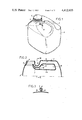
- FIG. 1 is a perspective view of a jug according to this invention
- FIG. 2 is a vertical section through the jug of FIG. 1;
- FIG. 3 is a section taken along line III--III of FIG. 2;
- FIG. 4 is a section similar to that of FIG. 2 but showing another jug according to the present invention.
- FIG. 5 is a section taken along line V--V of FIG. 4.
- a jug according to this invention has a standard vessel body 2 whose bottom is flat and whose top wall 2a is formed with a handle 3 and with a collar 4 that defines an upwardly open pour mouth 5 and that is normally covered by an internally threaded cap 6 of standard design.
- the handle 3 is tubular and has a rear end 12 joined to and opening downwardly into the jug body 2 and a front end 11 that is spaced from the collar 4 and that opens downwardly into the rear end of a U-shaped tube 7 having a front end joined to the mouth 5.
- This tube 7 defines a passage 8 that communicates with the passage 9 formed by the handle 3.
- the jug according to this invention is symmetrical about a center plane that is the section plane of FIG. 2. It can therefore be produced at low cost by blow molding.
- a stiff web 10 is formed between the lower wall of the tube 7 and the top wall 2a. Since the handle 2 stops short of the collar 4, and is joined to the top wall 2a by mainly upright ends 11 and 12, this handle is quite strong.
- the top edge of the handle 2 is level with the top surface of the cap 6 when same is screwed down, so that such jugs can be stacked atop one other.
- FIGS. 4 and 5 show a substantially identical arrangement, but here the web 11' is not completely closed, forming an upright small-diameter passage 13 extending from the lowest portion of the U-passage 8 to the interior of the jug body 2. Any liquid that becomes trapped in this passage 8 during refilling or when the jug is tipped when closed can drain via the passage branch 13 from this passage 8 as the jug stands. Thus there will not even be a temporary blockage of the passage 8 at the start of pouring when the passage 8 has somehow trapped a quantity of liquid.
- the flow cross-section of the passage branch 13 is substantially smaller than that of the passage 8.
- pressure in the passage 8 will be higher than the pressure urging the liquid into the lower end of the branch 13.
- the vented container according to this invention therefore functions automatically.
- the user need merely uncap the jug and pour, and will be assured of smooth pouring due to the vent.
- the jug can nonetheless be produced at the same cost as unvented jugs, and is as convenient to use, store, and ship.
Abstract
Description
Claims (9)
Applications Claiming Priority (4)
| Application Number | Priority Date | Filing Date | Title |
|---|---|---|---|
| FR8103482A FR2499943A1 (en) | 1981-02-17 | 1981-02-17 | Blow moulded containers with venting via the handle - reinforced by parison pinch alongside the spout to support stacking |
| FR8103482 | 1981-02-17 | ||
| FR8110835A FR2506724B2 (en) | 1981-05-26 | 1981-05-26 | CAN OF SYNTHETIC MATERIAL HAVING A FLOW REGULATOR |
| FR8110835 | 1981-05-26 |
Publications (1)
| Publication Number | Publication Date |
|---|---|
| US4412633A true US4412633A (en) | 1983-11-01 |
Family
ID=26222240
Family Applications (1)
| Application Number | Title | Priority Date | Filing Date |
|---|---|---|---|
| US06/349,172 Expired - Fee Related US4412633A (en) | 1981-02-17 | 1982-02-16 | Vented synthetic-resin jug |
Country Status (3)
| Country | Link |
|---|---|
| US (1) | US4412633A (en) |
| EP (1) | EP0058624B1 (en) |
| DE (1) | DE3264162D1 (en) |
Cited By (53)
| Publication number | Priority date | Publication date | Assignee | Title |
|---|---|---|---|---|
| US4579260A (en) * | 1984-02-13 | 1986-04-01 | Plastipak Packaging, Inc. | Plastic blow-molded container having dispensing valve |
| WO1987001677A1 (en) * | 1985-09-16 | 1987-03-26 | Goodall Donald T | Liquid dispenser |
| US4804119A (en) * | 1985-12-06 | 1989-02-14 | Goodall Donald T | Liquid dispenser |
| US4838464A (en) * | 1987-06-11 | 1989-06-13 | Graham Engineering Corporation | Vented plastic bottle |
| US5007565A (en) * | 1984-06-21 | 1991-04-16 | The Coca-Cola Company | Integral vent tube |
| US5114028A (en) * | 1990-06-20 | 1992-05-19 | Ring Can Corporation | Container with integral handle structure |
| US5299710A (en) * | 1993-01-27 | 1994-04-05 | Strottman International, Inc. | Drink container |
| US5301829A (en) * | 1993-03-24 | 1994-04-12 | Blitz U.S.A., Inc. | Combination fuel container and tool tray |
| US5340000A (en) * | 1993-07-13 | 1994-08-23 | Ring Can Corporation | Vented plastic bottle |
| US5346106A (en) * | 1993-12-01 | 1994-09-13 | Ring Can Corporation | Container having no-glug pouring spout |
| US5406994A (en) * | 1992-07-24 | 1995-04-18 | Briggs & Stratton Corporation | Portable gasoline container |
| USD380148S (en) * | 1995-07-19 | 1997-06-24 | Monsanto Company Of St. Louis | Dispensing system |
| USD380682S (en) * | 1995-09-29 | 1997-07-08 | Owens-Brockway Plastic Products Inc. | Plastic container |
| US5794824A (en) * | 1992-10-07 | 1998-08-18 | Jeong; Chang-Rock | Vessel for containing liquid |
| US5897035A (en) * | 1997-02-13 | 1999-04-27 | Felix Bottcher Gmbh & Co. | Fluid container for shipping and storing fluids |
| USD415033S (en) * | 1998-06-30 | 1999-10-12 | Zeneca Limited | Container |
| USD434666S (en) * | 1999-03-26 | 2000-12-05 | Aloe Health LC | Container with handle |
| US6360924B1 (en) * | 1998-11-06 | 2002-03-26 | Franzotech Invest Ab | Container |
| US6382475B1 (en) * | 1999-03-15 | 2002-05-07 | “Pack-Pro”Kunstostoff- und Metallverpackungs GmbH | Pouring device for a canister-type container |
| US6460741B1 (en) * | 1997-06-11 | 2002-10-08 | I-Chung Ho | Spill-resistant bottle for liquids and the like |
| USD472145S1 (en) | 2001-08-14 | 2003-03-25 | Nottingham-Spirk Partners, Llc | Paint container lid |
| USD473790S1 (en) | 2001-08-14 | 2003-04-29 | Nottingham-Spirk Partners, Llc | Paint container insert |
| USD480973S1 (en) | 2001-08-14 | 2003-10-21 | Nsi Innovation Llp | Design for a round paint container |
| USD482973S1 (en) | 2001-08-14 | 2003-12-02 | Nsi Innovation Llc | Square paint container |
| US6758375B2 (en) | 1997-06-11 | 2004-07-06 | I-Chung Ho | Spill-resistant, smoother pouring container for liquids |
| US20040211748A1 (en) * | 2003-04-25 | 2004-10-28 | Glenn Bartlett | Molded container with anti-glug vent tube and pinched handle |
| US20050011915A1 (en) * | 2003-07-16 | 2005-01-20 | Douglas Dygert | Vented plastic bottle |
| US20050092780A1 (en) * | 2002-03-05 | 2005-05-05 | Shigeru Yamana | Container with air intake mechanism |
| US6983862B2 (en) | 2001-04-18 | 2006-01-10 | The Sherwin-Williams Company | Container and lid assembly |
| US20070023461A1 (en) * | 2005-08-01 | 2007-02-01 | Chrisharr Technologies, Inc. | Flow controls for containers of liquids and viscous materials |
| US20070023384A1 (en) * | 2005-08-01 | 2007-02-01 | Janeczek James D | Container and blow mold assembly |
| US20070199945A1 (en) * | 2006-02-28 | 2007-08-30 | I-Chung Ho | Low cost spill-resistant cup |
| US20080000920A1 (en) * | 2006-02-28 | 2008-01-03 | I-Chung Ho | Low Cost Spill-Resistant Cup For Liquids |
| US20080035637A1 (en) * | 2006-08-09 | 2008-02-14 | Producers Dairy Foods, Inc. | Self-supporting liquid container for boxless storage, shipping and display |
| US20080078765A1 (en) * | 2006-08-21 | 2008-04-03 | Tropicana Products, Inc. | Container Having Improved Pouring Characteristics |
| DE102009021997A1 (en) * | 2009-05-19 | 2010-11-25 | Fhw-Moulds Gmbh | Stackable container, particularly stackable can, for storage and transport of liquids, has pouring neck molded in border area at container upper side with lockable outlet opening |
| US20110132863A1 (en) * | 2009-12-04 | 2011-06-09 | Plastipak Packaging, Inc. | Plastic container configured for case-less shipping |
| US20110132790A1 (en) * | 2009-12-04 | 2011-06-09 | Plastipak Packaging, Inc. | Stackable plastic container |
| US7959044B1 (en) | 2010-05-17 | 2011-06-14 | Alharr Technologies, Inc | Dual air vent bypass (DAVB) container |
| CN102180294A (en) * | 2011-04-15 | 2011-09-14 | 长沙市德泽实业有限公司 | Plastic barrel with exhaust handle |
| AU2005242173B2 (en) * | 2004-12-08 | 2012-04-05 | Vip Plastic Packaging Pty Ltd | Anti-Glug Container |
| US20120228183A1 (en) * | 2011-03-10 | 2012-09-13 | Graham Packaging Company, L.P. | Blow molded plastic container having improved top load strength |
| US8640930B2 (en) | 2010-03-11 | 2014-02-04 | Diversey, Inc. | Vent tube apparatus and method |
| US8662358B2 (en) | 2010-02-02 | 2014-03-04 | Diversey, Inc. | Liquid dispensing container and method |
| CN103863639A (en) * | 2013-12-13 | 2014-06-18 | 李清意 | Plastic bucket |
| USD747968S1 (en) | 2011-11-15 | 2016-01-26 | Husqvarna Ab | Bottle |
| US9302809B1 (en) * | 2015-02-04 | 2016-04-05 | Timothy W. Hooper | Stackable, stabilized fuel containers |
| US20190031401A1 (en) * | 2016-02-02 | 2019-01-31 | Silgan Dispensing Systems Corporation | Dispensing systems and methods for using the same |
| US10259622B2 (en) * | 2015-04-11 | 2019-04-16 | Joseph M. Hill | Liquid dispensing spout |
| USD849547S1 (en) * | 2016-06-03 | 2019-05-28 | Wd-40 Company | Bottle |
| US10391508B2 (en) * | 2017-06-29 | 2019-08-27 | Silgan Plastics Llc | Container for nested sprayer handle |
| USD870549S1 (en) | 2018-12-17 | 2019-12-24 | Kost Usa, Inc. | Bottle |
| CN114080354A (en) * | 2019-04-30 | 2022-02-22 | B和T产品有限公司 | Fuel container |
Families Citing this family (4)
| Publication number | Priority date | Publication date | Assignee | Title |
|---|---|---|---|---|
| FR2675771B1 (en) * | 1991-04-29 | 1993-08-20 | Itm Entreprises | CONTAINER OF MOLDED SYNTHETIC MATERIAL, OF CANISTER TYPE OR THE LIKE, COMPRISING MEANS OF CONTROLLING FLOW. |
| DE9406266U1 (en) * | 1994-04-15 | 1994-06-30 | Frohn Walter | Containers for the transport of dangerous liquids |
| SE9703162D0 (en) * | 1997-09-03 | 1997-09-03 | Hugo Nilsson | Container |
| PL424237A1 (en) * | 2018-01-09 | 2019-07-15 | Suwary Development Spółka Z Ograniczoną Odpowiedzialnością | Canister |
Citations (4)
| Publication number | Priority date | Publication date | Assignee | Title |
|---|---|---|---|---|
| US3251514A (en) * | 1964-03-13 | 1966-05-17 | Container Supply Company | Liquid dispensing jug having a vented handle |
| US3308997A (en) * | 1965-10-11 | 1967-03-14 | Crystal Preforming And Packagi | Plastic jug |
| US3434635A (en) * | 1967-03-21 | 1969-03-25 | Hunt Wesson Foods Inc | Container having a spout and a hollow handle |
| US4030664A (en) * | 1976-04-12 | 1977-06-21 | Custom Plastics, Inc. | Spraying and watering can |
Family Cites Families (5)
| Publication number | Priority date | Publication date | Assignee | Title |
|---|---|---|---|---|
| GB1024763A (en) * | 1962-11-12 | 1966-04-06 | Airfix Plastics Ltd | Improvements in or relating to hand-carried containers for liquids |
| US3198367A (en) * | 1963-01-30 | 1965-08-03 | Donald E Stickney | Bottle |
| LU48202A1 (en) | 1964-03-16 | 1965-05-17 | ||
| FR1456722A (en) * | 1965-08-20 | 1966-07-08 | Crystal Preforming & Packaging | Container structure |
| BE760027A (en) * | 1969-12-12 | 1971-06-08 | Saint Gobain Pont A Mousson | CONTAINER FOR LIQUID, EQUIPPED WITH A DEVICE |
-
1982
- 1982-02-03 EP EP82420021A patent/EP0058624B1/en not_active Expired
- 1982-02-03 DE DE8282420021T patent/DE3264162D1/en not_active Expired
- 1982-02-16 US US06/349,172 patent/US4412633A/en not_active Expired - Fee Related
Patent Citations (4)
| Publication number | Priority date | Publication date | Assignee | Title |
|---|---|---|---|---|
| US3251514A (en) * | 1964-03-13 | 1966-05-17 | Container Supply Company | Liquid dispensing jug having a vented handle |
| US3308997A (en) * | 1965-10-11 | 1967-03-14 | Crystal Preforming And Packagi | Plastic jug |
| US3434635A (en) * | 1967-03-21 | 1969-03-25 | Hunt Wesson Foods Inc | Container having a spout and a hollow handle |
| US4030664A (en) * | 1976-04-12 | 1977-06-21 | Custom Plastics, Inc. | Spraying and watering can |
Cited By (72)
| Publication number | Priority date | Publication date | Assignee | Title |
|---|---|---|---|---|
| US4579260A (en) * | 1984-02-13 | 1986-04-01 | Plastipak Packaging, Inc. | Plastic blow-molded container having dispensing valve |
| US5007565A (en) * | 1984-06-21 | 1991-04-16 | The Coca-Cola Company | Integral vent tube |
| WO1987001677A1 (en) * | 1985-09-16 | 1987-03-26 | Goodall Donald T | Liquid dispenser |
| US4804119A (en) * | 1985-12-06 | 1989-02-14 | Goodall Donald T | Liquid dispenser |
| US4838464A (en) * | 1987-06-11 | 1989-06-13 | Graham Engineering Corporation | Vented plastic bottle |
| US5114028A (en) * | 1990-06-20 | 1992-05-19 | Ring Can Corporation | Container with integral handle structure |
| US5406994A (en) * | 1992-07-24 | 1995-04-18 | Briggs & Stratton Corporation | Portable gasoline container |
| US5794824A (en) * | 1992-10-07 | 1998-08-18 | Jeong; Chang-Rock | Vessel for containing liquid |
| US5299710A (en) * | 1993-01-27 | 1994-04-05 | Strottman International, Inc. | Drink container |
| US5301829A (en) * | 1993-03-24 | 1994-04-12 | Blitz U.S.A., Inc. | Combination fuel container and tool tray |
| WO1995002352A1 (en) * | 1993-07-13 | 1995-01-26 | Ring Can Corporation | Vented plastic bottle |
| US5340000A (en) * | 1993-07-13 | 1994-08-23 | Ring Can Corporation | Vented plastic bottle |
| US5346106A (en) * | 1993-12-01 | 1994-09-13 | Ring Can Corporation | Container having no-glug pouring spout |
| WO1995015104A1 (en) * | 1993-12-01 | 1995-06-08 | Ring Can Corporation | Container having no-glug pouring spout |
| EP1544115A1 (en) | 1993-12-01 | 2005-06-22 | Ring Can Corporation | Container having no-glug pouring spout |
| USD380148S (en) * | 1995-07-19 | 1997-06-24 | Monsanto Company Of St. Louis | Dispensing system |
| USD380682S (en) * | 1995-09-29 | 1997-07-08 | Owens-Brockway Plastic Products Inc. | Plastic container |
| US5897035A (en) * | 1997-02-13 | 1999-04-27 | Felix Bottcher Gmbh & Co. | Fluid container for shipping and storing fluids |
| US6460741B1 (en) * | 1997-06-11 | 2002-10-08 | I-Chung Ho | Spill-resistant bottle for liquids and the like |
| US6758375B2 (en) | 1997-06-11 | 2004-07-06 | I-Chung Ho | Spill-resistant, smoother pouring container for liquids |
| USD415033S (en) * | 1998-06-30 | 1999-10-12 | Zeneca Limited | Container |
| US6360924B1 (en) * | 1998-11-06 | 2002-03-26 | Franzotech Invest Ab | Container |
| US6382475B1 (en) * | 1999-03-15 | 2002-05-07 | “Pack-Pro”Kunstostoff- und Metallverpackungs GmbH | Pouring device for a canister-type container |
| USD434666S (en) * | 1999-03-26 | 2000-12-05 | Aloe Health LC | Container with handle |
| US6983862B2 (en) | 2001-04-18 | 2006-01-10 | The Sherwin-Williams Company | Container and lid assembly |
| USD482973S1 (en) | 2001-08-14 | 2003-12-02 | Nsi Innovation Llc | Square paint container |
| USD473790S1 (en) | 2001-08-14 | 2003-04-29 | Nottingham-Spirk Partners, Llc | Paint container insert |
| USD480973S1 (en) | 2001-08-14 | 2003-10-21 | Nsi Innovation Llp | Design for a round paint container |
| USD472145S1 (en) | 2001-08-14 | 2003-03-25 | Nottingham-Spirk Partners, Llc | Paint container lid |
| US7331490B2 (en) * | 2002-03-05 | 2008-02-19 | Aicello Chemical Co., Ltd. | Container with air intake mechanism |
| US20050092780A1 (en) * | 2002-03-05 | 2005-05-05 | Shigeru Yamana | Container with air intake mechanism |
| US20040211748A1 (en) * | 2003-04-25 | 2004-10-28 | Glenn Bartlett | Molded container with anti-glug vent tube and pinched handle |
| US7086548B2 (en) * | 2003-04-25 | 2006-08-08 | Reliance Products Limited Partnership | Molded container with anti-glug vent tube and pinched handle |
| US6994233B2 (en) * | 2003-07-16 | 2006-02-07 | Ring Container Technologies, Inc. | Vented plastic bottle |
| US20050011915A1 (en) * | 2003-07-16 | 2005-01-20 | Douglas Dygert | Vented plastic bottle |
| AU2005242173B2 (en) * | 2004-12-08 | 2012-04-05 | Vip Plastic Packaging Pty Ltd | Anti-Glug Container |
| US20070023461A1 (en) * | 2005-08-01 | 2007-02-01 | Chrisharr Technologies, Inc. | Flow controls for containers of liquids and viscous materials |
| US20070023384A1 (en) * | 2005-08-01 | 2007-02-01 | Janeczek James D | Container and blow mold assembly |
| US20070199945A1 (en) * | 2006-02-28 | 2007-08-30 | I-Chung Ho | Low cost spill-resistant cup |
| US20070199961A1 (en) * | 2006-02-28 | 2007-08-30 | I-Chung Ho | Low cost spill-and-glug-resistant cup and container |
| US20080000920A1 (en) * | 2006-02-28 | 2008-01-03 | I-Chung Ho | Low Cost Spill-Resistant Cup For Liquids |
| US7641070B2 (en) | 2006-02-28 | 2010-01-05 | Edison Nation, Llc | Low cost spill-resistant cup for liquids |
| US7757886B2 (en) | 2006-02-28 | 2010-07-20 | Edison Nation, Llc | Low cost spill-and-glug-resistant cup and container |
| US20100200601A1 (en) * | 2006-02-28 | 2010-08-12 | Edison Nation, Llc | Low cost spill-resistant cup |
| US20080035637A1 (en) * | 2006-08-09 | 2008-02-14 | Producers Dairy Foods, Inc. | Self-supporting liquid container for boxless storage, shipping and display |
| US8678215B2 (en) * | 2006-08-21 | 2014-03-25 | Tropicana Products, Inc. | Container having improved pouring characteristics |
| US20080078765A1 (en) * | 2006-08-21 | 2008-04-03 | Tropicana Products, Inc. | Container Having Improved Pouring Characteristics |
| DE102009021997A1 (en) * | 2009-05-19 | 2010-11-25 | Fhw-Moulds Gmbh | Stackable container, particularly stackable can, for storage and transport of liquids, has pouring neck molded in border area at container upper side with lockable outlet opening |
| US9352873B2 (en) | 2009-12-04 | 2016-05-31 | Plastipak Packaging, Inc. | Plastic container configured for case-less shipping |
| US20110132790A1 (en) * | 2009-12-04 | 2011-06-09 | Plastipak Packaging, Inc. | Stackable plastic container |
| US10518933B2 (en) | 2009-12-04 | 2019-12-31 | Plastipak Packaging, Inc. | Stackable plastic container |
| US20110132863A1 (en) * | 2009-12-04 | 2011-06-09 | Plastipak Packaging, Inc. | Plastic container configured for case-less shipping |
| US8998042B2 (en) | 2010-02-02 | 2015-04-07 | Diversey, Inc. | Liquid dispensng container and method |
| US8662358B2 (en) | 2010-02-02 | 2014-03-04 | Diversey, Inc. | Liquid dispensing container and method |
| US8640930B2 (en) | 2010-03-11 | 2014-02-04 | Diversey, Inc. | Vent tube apparatus and method |
| US7959044B1 (en) | 2010-05-17 | 2011-06-14 | Alharr Technologies, Inc | Dual air vent bypass (DAVB) container |
| US20120228183A1 (en) * | 2011-03-10 | 2012-09-13 | Graham Packaging Company, L.P. | Blow molded plastic container having improved top load strength |
| US9174759B2 (en) * | 2011-03-10 | 2015-11-03 | Graham Packaging Company, L.P. | Blow molded plastic container having improved top load strength |
| CN102180294A (en) * | 2011-04-15 | 2011-09-14 | 长沙市德泽实业有限公司 | Plastic barrel with exhaust handle |
| USD747968S1 (en) | 2011-11-15 | 2016-01-26 | Husqvarna Ab | Bottle |
| USD747976S1 (en) | 2011-11-15 | 2016-01-26 | Husqvarna Ab | Bottle |
| CN103863639A (en) * | 2013-12-13 | 2014-06-18 | 李清意 | Plastic bucket |
| US9302809B1 (en) * | 2015-02-04 | 2016-04-05 | Timothy W. Hooper | Stackable, stabilized fuel containers |
| US10259622B2 (en) * | 2015-04-11 | 2019-04-16 | Joseph M. Hill | Liquid dispensing spout |
| US20190031401A1 (en) * | 2016-02-02 | 2019-01-31 | Silgan Dispensing Systems Corporation | Dispensing systems and methods for using the same |
| US10807769B2 (en) * | 2016-02-02 | 2020-10-20 | Silgan Dispensing Systems Corporation | Dispensing systems and methods for using the same |
| US11655075B2 (en) | 2016-02-02 | 2023-05-23 | Silgan Dispensing Systems Corporation | Dispensing systems and methods for using the same |
| USD849547S1 (en) * | 2016-06-03 | 2019-05-28 | Wd-40 Company | Bottle |
| US10391508B2 (en) * | 2017-06-29 | 2019-08-27 | Silgan Plastics Llc | Container for nested sprayer handle |
| US10625285B2 (en) | 2017-06-29 | 2020-04-21 | Silgan Plastics Llc | Container for nested sprayer handle |
| USD870549S1 (en) | 2018-12-17 | 2019-12-24 | Kost Usa, Inc. | Bottle |
| CN114080354A (en) * | 2019-04-30 | 2022-02-22 | B和T产品有限公司 | Fuel container |
Also Published As
| Publication number | Publication date |
|---|---|
| EP0058624B1 (en) | 1985-06-19 |
| EP0058624A1 (en) | 1982-08-25 |
| DE3264162D1 (en) | 1985-07-25 |
Similar Documents
| Publication | Publication Date | Title |
|---|---|---|
| US4412633A (en) | Vented synthetic-resin jug | |
| US5232110A (en) | Container closure | |
| US5346106A (en) | Container having no-glug pouring spout | |
| US3066819A (en) | Free-pouring jug | |
| US3251514A (en) | Liquid dispensing jug having a vented handle | |
| US4061253A (en) | Metering dispensing bottle | |
| US4779771A (en) | Partitioned box for pouring a measured amount of a granulated solid | |
| JPS6470365A (en) | Plastic cover for plastic vessel | |
| CA1252436A (en) | Liquid-dispensing container | |
| US5497916A (en) | Liquid dispenser featuring automatic pouring of measured doses | |
| US2825495A (en) | Screw top liquor dispenser for bottles | |
| US6378741B1 (en) | Dosing bottle for dispensing fixed doses of liquids | |
| US5148953A (en) | Device for the apportioned delivery of liquids | |
| US3362607A (en) | Container with drinking tube | |
| CA1202580A (en) | Container for liquids | |
| US20050006420A1 (en) | Container for storing and pouring liquids | |
| US6520386B2 (en) | Overfill safety spout for fluid container | |
| JP2546773Y2 (en) | Liquid refill container | |
| KR100708415B1 (en) | A cover of a liguid container | |
| AU2005242173B2 (en) | Anti-Glug Container | |
| JPS6219559Y2 (en) | ||
| JPS588197Y2 (en) | Pump type liquid container | |
| JP2537172Y2 (en) | Measuring tap for liquid dispensing container | |
| JPH04121262U (en) | liquid dispensing cap | |
| JP3771014B2 (en) | Container with metering tap |
Legal Events
| Date | Code | Title | Description |
|---|---|---|---|
| AS | Assignment |
Owner name: SEPROSY SOCIETE EUROPEENNE POUR LA TRANSFORMATION Free format text: ASSIGNMENT OF ASSIGNORS INTEREST.;ASSIGNORS:GUERRAZZI, VINCENT;VENDRAMINI, VALERIO;REEL/FRAME:004160/0474 Effective date: 19830705 Owner name: SEPROSY SOCIETE EUROPEENNE POUR LA TRANSFORMATION Free format text: ASSIGNMENT OF ASSIGNORS INTEREST;ASSIGNORS:GUERRAZZI, VINCENT;VENDRAMINI, VALERIO;REEL/FRAME:004160/0474 Effective date: 19830705 |
|
| MAFP | Maintenance fee payment |
Free format text: PAYMENT OF MAINTENANCE FEE, 4TH YEAR, PL 96-517 (ORIGINAL EVENT CODE: M170); ENTITY STATUS OF PATENT OWNER: LARGE ENTITY Year of fee payment: 4 |
|
| FEPP | Fee payment procedure |
Free format text: PAYOR NUMBER ASSIGNED (ORIGINAL EVENT CODE: ASPN); ENTITY STATUS OF PATENT OWNER: LARGE ENTITY |
|
| MAFP | Maintenance fee payment |
Free format text: PAYMENT OF MAINTENANCE FEE, 8TH YEAR, PL 96-517 (ORIGINAL EVENT CODE: M171); ENTITY STATUS OF PATENT OWNER: LARGE ENTITY Year of fee payment: 8 |
|
| FEPP | Fee payment procedure |
Free format text: MAINTENANCE FEE REMINDER MAILED (ORIGINAL EVENT CODE: REM.); ENTITY STATUS OF PATENT OWNER: LARGE ENTITY |
|
| LAPS | Lapse for failure to pay maintenance fees | ||
| FP | Lapsed due to failure to pay maintenance fee |
Effective date: 19951101 |
|
| STCH | Information on status: patent discontinuation |
Free format text: PATENT EXPIRED DUE TO NONPAYMENT OF MAINTENANCE FEES UNDER 37 CFR 1.362 |