US4418983A - Optical waveguide connector - Google Patents
Optical waveguide connector Download PDFInfo
- Publication number
- US4418983A US4418983A US06/244,526 US24452681A US4418983A US 4418983 A US4418983 A US 4418983A US 24452681 A US24452681 A US 24452681A US 4418983 A US4418983 A US 4418983A
- Authority
- US
- United States
- Prior art keywords
- fiber
- receptacle
- plug
- bore
- nose
- Prior art date
- Legal status (The legal status is an assumption and is not a legal conclusion. Google has not performed a legal analysis and makes no representation as to the accuracy of the status listed.)
- Expired - Lifetime
Links
Images


Classifications
-
- G—PHYSICS
- G02—OPTICS
- G02B—OPTICAL ELEMENTS, SYSTEMS OR APPARATUS
- G02B6/00—Light guides; Structural details of arrangements comprising light guides and other optical elements, e.g. couplings
- G02B6/24—Coupling light guides
- G02B6/36—Mechanical coupling means
- G02B6/38—Mechanical coupling means having fibre to fibre mating means
- G02B6/3807—Dismountable connectors, i.e. comprising plugs
- G02B6/389—Dismountable connectors, i.e. comprising plugs characterised by the method of fastening connecting plugs and sockets, e.g. screw- or nut-lock, snap-in, bayonet type
- G02B6/3893—Push-pull type, e.g. snap-in, push-on
-
- G—PHYSICS
- G02—OPTICS
- G02B—OPTICAL ELEMENTS, SYSTEMS OR APPARATUS
- G02B6/00—Light guides; Structural details of arrangements comprising light guides and other optical elements, e.g. couplings
- G02B6/24—Coupling light guides
- G02B6/36—Mechanical coupling means
- G02B6/38—Mechanical coupling means having fibre to fibre mating means
- G02B6/3807—Dismountable connectors, i.e. comprising plugs
- G02B6/3833—Details of mounting fibres in ferrules; Assembly methods; Manufacture
- G02B6/3834—Means for centering or aligning the light guide within the ferrule
- G02B6/3838—Means for centering or aligning the light guide within the ferrule using grooves for light guides
-
- G—PHYSICS
- G02—OPTICS
- G02B—OPTICAL ELEMENTS, SYSTEMS OR APPARATUS
- G02B6/00—Light guides; Structural details of arrangements comprising light guides and other optical elements, e.g. couplings
- G02B6/24—Coupling light guides
- G02B6/36—Mechanical coupling means
- G02B6/38—Mechanical coupling means having fibre to fibre mating means
- G02B6/3807—Dismountable connectors, i.e. comprising plugs
- G02B6/3873—Connectors using guide surfaces for aligning ferrule ends, e.g. tubes, sleeves, V-grooves, rods, pins, balls
- G02B6/3874—Connectors using guide surfaces for aligning ferrule ends, e.g. tubes, sleeves, V-grooves, rods, pins, balls using tubes, sleeves to align ferrules
- G02B6/3878—Connectors using guide surfaces for aligning ferrule ends, e.g. tubes, sleeves, V-grooves, rods, pins, balls using tubes, sleeves to align ferrules comprising a plurality of ferrules, branching and break-out means
- G02B6/3879—Linking of individual connector plugs to an overconnector, e.g. using clamps, clips, common housings comprising several individual connector plugs
-
- G—PHYSICS
- G02—OPTICS
- G02B—OPTICAL ELEMENTS, SYSTEMS OR APPARATUS
- G02B6/00—Light guides; Structural details of arrangements comprising light guides and other optical elements, e.g. couplings
- G02B6/24—Coupling light guides
- G02B6/36—Mechanical coupling means
- G02B6/38—Mechanical coupling means having fibre to fibre mating means
- G02B6/3807—Dismountable connectors, i.e. comprising plugs
- G02B6/3887—Anchoring optical cables to connector housings, e.g. strain relief features
- G02B6/3888—Protection from over-extension or over-compression
-
- G—PHYSICS
- G02—OPTICS
- G02B—OPTICAL ELEMENTS, SYSTEMS OR APPARATUS
- G02B6/00—Light guides; Structural details of arrangements comprising light guides and other optical elements, e.g. couplings
- G02B6/24—Coupling light guides
- G02B6/36—Mechanical coupling means
- G02B6/38—Mechanical coupling means having fibre to fibre mating means
- G02B6/3807—Dismountable connectors, i.e. comprising plugs
- G02B6/3897—Connectors fixed to housings, casing, frames or circuit boards
-
- G—PHYSICS
- G02—OPTICS
- G02B—OPTICAL ELEMENTS, SYSTEMS OR APPARATUS
- G02B6/00—Light guides; Structural details of arrangements comprising light guides and other optical elements, e.g. couplings
- G02B6/24—Coupling light guides
- G02B6/42—Coupling light guides with opto-electronic elements
- G02B6/4292—Coupling light guides with opto-electronic elements the light guide being disconnectable from the opto-electronic element, e.g. mutually self aligning arrangements
-
- G—PHYSICS
- G02—OPTICS
- G02B—OPTICAL ELEMENTS, SYSTEMS OR APPARATUS
- G02B6/00—Light guides; Structural details of arrangements comprising light guides and other optical elements, e.g. couplings
- G02B6/24—Coupling light guides
- G02B6/36—Mechanical coupling means
- G02B6/38—Mechanical coupling means having fibre to fibre mating means
- G02B6/3807—Dismountable connectors, i.e. comprising plugs
- G02B6/3833—Details of mounting fibres in ferrules; Assembly methods; Manufacture
- G02B6/3851—Ferrules having keying or coding means
Definitions
- the present invention relates to optical fiber connections in general, and in particular to fiber connectors comprising a plug component which functions to axially locate a single optical fiber on the axis of a receptacle bore, and means for mechanically affixing the plug component to the optical cable.
- a further problem confronted by fiber optic connector technology is attributable to the fact that a variety of cable sizes exist in the industry.
- the relatively large plastic fiber used in certain systems can range in size between 16 to 40 thousandths of an inch. Consequently, the connectors for terminating these fibers must accommodate this wide range of potential fiber sizes, which further complicates the achievement of a suitable connector system.
- the outer diameter of jacket which protects the fibers in a cabling structure can also vary.
- Presently available connectors because of their alignment techniques, have difficulty in accommodating the termination of the wide range of cable sizes which a user mush confront in the optical cable world.
- the present invention relates to an inexpensive connector for axially aligning a pair of optical fibers, comprising a receptacle body having a bore extending therethrough, a pair of plug members for intended opposed location within the receptacle bore, and a pair of retention devices for mechanically affixing each plug member of a respective cable.
- Each plug member is provided with an axial passageway receiving one fiber therein, and a forward alignment nose portion having a profiled opening for receiving a forward end of the fiber.
- the opening is defined by opposed V-grooves, with the upper and lower V-grooves separated by a transverse slot which extends through the alignment nose portion.
- each plug member is further provided with exterior protrusions which are located to engage the receptacle body, causing radial compression of the V-grooves upon the fiber extending therebetween. Resultingly, the fiber is wedged between the V-groove surfaces, and is located on the axis of the receptacle bore.
- An annular, compressible flange is further provided to extend around each plug member, at a location axially rearward of the forward alignment portion of the plug. The annular flange likewise engages the receptacle to axially center the rearward portion of the plug member, and to environmentally seal the plug bore.
- Each plug member receives a retention sleeve into a rearward portion of the passageway; the retention sleeve having tine projection means for inhibiting rearward withdrawal of the optical cable from the plug member.
- a further object of the present invention is to provide a connector capable of aligning a pair of optical fibers, having outer diameters variable within specified limits.
- Yet a further object of the present invention is to provide a connector for optically coupling a pair of fibers, a feature of which is having a unitary alignment plug.
- a further object of the present invention is to provide an optical waveguide connector which requires no specialized tools in effectuating a fiber termination.
- Still a further object of the present invention is to provide an optical waveguide connector for optically coupling a pair of optical fibers, and which obviates the need for polishing end surfaces of the fibers in effectuating the coupling.
- a further object is to provide an optical connector suitable for terminating large diameter plastic fiber cables.
- Yet a further object of the present invention is to provide an optical waveguide connector for coupling a pair of optical fibers without the need for adhesive materials.
- a still further object of the present invention is to provide a waveguide connector which is economically and readily produced.
- An object of the present invention is to provide an optical waveguide connector featured having single line mating plug and receptacle components, which couple without a requirement of keying structure, thereby eliminating the risk of mismating.
- a further object of the present invention is to provide an optical waveguide connector composed of a relatively few component parts.
- Still a further object of the present invention is to provide an optical waveguide connector having alignment means operating directly upon the forward end of an optical waveguide.
- a further object is to provide a low profile optical waveguide connector, having positive latching structure.
- An object of the present invention is to provide an optical waveguide connector which is amenable to factory pre-assembly, and capable of expeditious application to an optical waveguide.
- Yet a further object is to provide an optical waveguide connector which is interchangeably suitable for simplex-to-duplex applications, or optionally duplex-to-duplex applications.
- FIG. 1 is an exploded perspective view of the subject connector plug, having an optical fiber and retention sleeve exploded therefrom. As indicated, the subject plug is intended for mating insertion into a bulkhead mounted receptacle.
- FIG. 2 is a side elevation view of the subject optical waveguide connector, illustrating the receptacle component having one of two connector plug subassemblies inserted therein, and the other plug assembly exploded therefrom.
- FIG. 3 is a partial side elevation view of the subject receptacle body, having the forward alignment portion of a plug member exploded therefrom.
- the plug member terminates an optical fiber of the type having a relatively larger diameter fiber core, and
- FIG. 3 illustrates the capability of the subject invention to terminate a fiber having a diametered size variable within a specified range of limits.
- FIG. 4 is a partial side elevation view of the subject receptacle body, with the plug and larger diameter fiber illustrated in FIG. 3 inserted into the axial bore of the receptacle.
- FIG. 5 is a frontal view of the subject connector plug, taken along the line 5--5 of FIG. 2.
- FIG. 6 is a frontal view taken through the alignment nose portion of the subject connector plug, taken along the line 6--6 of FIG. 2.
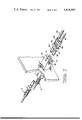
- FIG. 7 is an exploded perspective view of the subject invention illustrating a duplex receptacle configuration, illustrated having a duplex plug exploded therefrom and a pair of simplex plug members likewise exploded from an opposite end.
- FIG. 7 serves to illustrate the interchangeable features of the subject invention in simplex and duplex operating modes.
- FIG. 8 is a side elevation view taken through the duplex receptacle illustrated in FIG. 7, having the duplex plug member matably engaged therewith, along with one of the two simplex plug members.
- a second simplex plug member is illustrated exploded from the receptacle body for purpose of illustration.
- FIG. 9 is a perspective view of an active device module, having a simplex plug member exploded therefrom. Similarly, an active semiconductor package is illustrated in FIG. 9 detached from the module housing.
- FIG. 10 is a side elevation view through the active device module illustrated in FIG. 9 with the semiconductor package assembled within the module housing and the simplex plug assembled in the mating condition.
- a pair of plug members 2,3 each comprises a rearward portion 4, an intermediate portion 6, and a forward alignment nose 8.
- the plug members are composed of substantially resilient plastic material, and both of the plug members 2,3 are structurally identical.
- a series of annularly directed, and axially spaced gripping flanges 10 are provided integral with the rearward portion 4 of the plug member.
- a somewhat larger retention flange 12 is further provided and located between the rearward portion 4 and the intermediate portion 6 of each plug member.
- An axial bore extends through each of the plug members 2,3 and is comprised of a rearward bore 16, an intermediate bore 18, and a profiled opening 20 which projects through the alignment nose 8 of each plug member, and which communicates with the intermediate bore 18.
- the forward profiled opening 20 through the alignment nose 8 is defined by upper convergent surfaces 22, which converge away from the opening, and a pair of lower convergent surfaces 24 which converge downward and away from the opening.
- a transverse slot 26 is further provided to extend through the forward alignment nose 8 of each plug member, and is located so as to separate the upper convergent surfaces 22 from the lower surfaces 24.
- a pair of upper alignment protrusions 28, and a pair of lower alignment protrusions 30 are structured to be substantially resilient and compressible for a purpose to be explained in detail below.
- the upper protrusions 28 are positioned to be diametrically opposed to corresponding lower protrusions 30, with the upper and lower protrusions 28,30 being situated on opposite sides of the transverse slot 26.
- a tubular retention sleeve 32 is provided, structured to comprise a plurality of inwardly directed tines 34, and outwardly directed tines 36. It will be noted that the outwardly directed tines 36 project towards a rearward end of the retention sleeve 32, while the inwardly directed tines 34 project towards the forward end of the retention sleeve.
- the tubular retention sleeve 32 is composed of a suitable metallic composition, which provides spring-like characteristics. Resultingly, the inward and outward projecting tines 34,36 function as cantilever springs for purposes explained below.
- a bulkhead mounted receptacle 38 is shown, having an axial passageway 40 extending therethrough.
- a pair of cantilever fingers 42 extend outwardly, and provide latching flanges 44 at the respective remote ends thereof.
- a mounting flange 45 is provided about receptacle 38, and receives a pair of mounting screws 46 therethrough to affix the receptacle to the bulkhead.
- the receptacle body 38 is preferably composed of plastics material.
- the subject invention is intended to optically couple a pair of optical fiber, or waveguide, cables 48, which are structured having an interior fiber 50, and an outer jacket 52.
- the inner fiber 50 of such cables is typically composed of plastics material of optical quality, and can vary in diametric size between 16 to 40 thousandths of an inch.
- the jacket layer 52 which surrounds the interior fiber 50 functions to protect the fiber from external forces. Since the subject invention is intended to accommodate a termination of optical cables having a substantially wide range of dimension, operation of the connector will first be described for a fiber having an interior fiber of relatively small diametric dimension, and subsequently, a description of the operation of the subject invention will be presented for a cable having an interior fiber of relatively larger diametric dimension.
- the optical fiber cable 48 is prepared for termination by removing the jacket 52 from a forward end of the fiber 50. Thereafter, the fiber cable 48 is inserted through the tubular retention sleeve 32, and the plug member 2 as shown in FIG. 2. It will be appreciated that the inwardly directed tines 34 of the retention sleeve resiliently exert engaging pressure on the jacket 52 of the cable. Subsequently, as shown in FIG. 2, the retention sleeve 32 is inserted into the rearward bore 16 of the plug member 2. So located, the fiber cable 48 projects through the intermediate bore 18, and the fiber 50 projects through the profiled opening 20 of the alignment nose 8.
- the inward directed tines 34 are made to penetrate into the jacket 52 of the cable, to thereby mechanically engage the cable and inhibit rearward withdrawal of the cable from the retention sleeve.
- This axial tension further acts to draw the outward tines 36 of the retention sleeve 32 into penetrating engagement with the plug member rearward portion 4. Consequently, the retention sleeve is mechanically retained within the plug member, by operation of the outward directed tines 36.
- the fiber optic cable 48 is mechanically retained within the retention sleeve 32 by operation of the inward directed tines 34.
- the forward end of the fiber 50 projects through the profiled opening of alignment nose 8. Thereafter, by a cutting technique common within the industry, the forward end surface of the fiber 50 is severed into a coplanar relationship with the forward end surface of the plug member 2. So located, the fiber cable 48 extends forward through the intermediate portion 6 of the plug member, and a small unjacketed portion of the fiber 50 projects through the alignment nose 8 to a forward end of a plug member. As best illustrated in FIG. 5, the forward unjacketed portion of the fiber 50 is loosely contained between the convergent surfaces 22 and 24 of the alignment nose 8. The plug member is in a condition for insertion into the receptacle 38, as shown in FIG. 2.
- the cantilever fingers 42 ride over the retention flange 12 of the plug member, to mechanically lock the plug member into an engaging relationship with the receptacle.
- the protrusions 28,30 of the alignment portion 8 and the annular alignment rib 14 of the intermediate portion 6 of the plug member engage with the receptacle wall defining the passageway 40 and compress radially inward.
- the engagement between the alignment rib 14 and the receptacle wall serves to axially locate the plug member on the major axis of the passageway.
- engagement of the protrusions 28,30 of the nose portion serve to radially compress convergent surfaces 22 and 24 of the nose portion 8 about the fiber 50 as shown in FIG. 6.
- the compressible protrusions 28,30 engage the receptacle, and cause the surfaces 22 and 24 to wedge the optical fiber 50 therebetween.
- the transverse slot 26 accommodates radial movement of the surfaces toward the optical fiber. In wedging the fiber between surfaces 22 and 24, the fiber is thereby located on the major axis of the passageway of the receptacle.
- the presence of the transverse slot 26, and the compressible nature of the protrusions 28 and 30, operate to render the subject connector plug relatively insensitive to optical fiber dimensional variances.
- the interior dimensions of the intermediate bore 18 are sufficiently large to accommodate receipt of optical fiber cables having an outer diameter which may vary within a specified range.
- the alignment nose 8 is structured to accommodate optical fibers having diameters variable about nominal dimensions of 16 or 40 thousandths of an inch.
- the pair of plug members 2,3 are inserted into opposite ends of the passageway 40, and are brought into abutting opposition intermediate of the passageway. There located, the axes of the fiber 50 extending through the alignment nose portion of each plug member are in alignment on the major axis of the passageway 40, and an efficient optical coupling between two optical cables is thereby effectuated.
- the body of the intermediate portion 6 does not frictionally engage the receptacle, but rather, an axial gap 56 exists between the annular alignment rib 14 and the protrusions 28,30 of the plug member. This gap reduces insertion friction and enables the plug to be inserted with minimal amount of insertion force required.
- the plug member achieves an alignment function solely by operation of the rib 14 and the protrusions on the alignment nose 8 of the plug member.
- each of the subject connector plugs can accommodate receipt of an optical cable having a fiber diameter which is somewhat larger than the fiber illustrated in the preceeding discussion.
- a fiber of larger outer dimension is shown to project through the alignment portion 8 of the plug member in the manner described above.
- the oversize fiber still projects freely, but with less clearance, through the opening in the nose portion of the plug member, prior to insertion of the plug member into the receptacle passageway.
- the plug member is matingly inserted into the receptacle passageway as shown in FIG.
- the protrusions 28 and 30 of the nose portion compressibly engage the receptacle sidewalls lining the passageway, to locate the optical fiber 50 on the axis passageway.
- an inward dimple 54 is created by flexed material of the plug. The dimple 54 extends annularly around the intermediate plug portion 6, and stress relieves the plug member from forces generated by the protrusions 28,30 and the alignment rib 14.
- the subject invention described above comprises a connector plug of unitary configuration which is adapted to receive an optical cable having an interior bore and outer diameter dimension variable within limits. Further, no polishing is required when effectuating such a termination; nor is there a need for adhesive material in mechanically attaching the plug to the optical cables. Furthermore, since the termination of optical cable by operation of the subject invention requires no specialized tooling, it is therefore suitable for field applications. Lastly, the optical fiber connector is comprised of inexpensive-to-produce components which result in a connector of substantially lower manufacturing cost than currently available alternatives in the industry.
- the duplex plug 58 comprises a pair of forward projecting plug members 64,66, which are encased jointly in an elastomeric plug body 68.
- the plug body 68 is further provided with a rectangular retention flange 70 intermediate the length thereof and includes a keying projection 72 as shown.
- the keying projection 72 is located immediately forward of the retention flange 70 and along the external side of the plug member 66.
- the duplex receptacle 74 is provided with a keying slot 76 in one side thereof, and is further structured to provide a pair of parallel and adjacent axial bores 73,75 projecting therethrough. It will be appreciated that the receptacle 74 is a duplex version of the simplex receptacle 38 illustrated in FIG. 1. It will further be noted upon a combined consideration of FIGS. 7 and 8 that the duplex receptacle 74 is adapted to alternatively receive a duplex plug 58 therein, or a pair of simplex plugs 2,3.
- the alignment structure of the duplex and simplex plugs are identical and coaxial alignment of the optical waveguides terminated by each is as previously described. As shown in FIG.
- the keying projection 72 of the duplex plug 58 is aligned within the keying slot 76 of the receptacle.
- the simplex plugs 2,3, having no such keying projection, may be readily inserted into the duplex receptacle bores at the option of the user.
- the duplex receptacle 74 can matingly couple a pair of duplex plugs 58, or four simplex plugs such as 2,3, or a single duplex plug and a pair of simplex plugs.
- Such versatility enables the user of the subject invention to converge a pair of optical waveguides from remote locations on a printed circuit board to a single duplex receptacle, and then exit the duplex receptacle through a single duplex plug.
- an active device mount 78 may be used in combination with a simplex plug 2 as illustrated.
- the active device mount 78 comprises a low profile body 80 having slotted mounting flanges 82 extending therefrom at right angles for either vertical or horizontal (shown horizontal) mounting of the active device mount on a printed circuit board.
- a pair of parallel cantilever fingers 84 project forward of the module body 80, each having a latching flange 86 at the forward end thereof.
- the cantilever fingers 84 function similarly as the cantilever fingers 42 illustrated in FIG. 2.
- the body 80 is provided with an axial bore 88 extending therein, and communicating with a larger dimensioned counterbore 90 located in a rearward portion of the body.
- the counterbore 90 is adapted to receive an electro-optic device package 92 therein, having a plurality of leads 94 exiting the mount body at right angles.
- the active device package 92 includes an emitter or detector chip (not shown) which aligns on the axis of the mount body bore 88.
- the right angled leads 94 are intended for electrical engagement with the semiconductor chip, and project opposite ends through a printed circuit board 96 to establish electrical interconnections with circuitry on the printed circuit board.
- the simplex plug 2 is matingly inserted into a forward end of the active device mount 78, and serves to colinearly align an optical waveguide on the axis of the mount bore 88, thereby establishing an optical coupling with the semiconductor chip.
- the subject plug member is provided with alignment structure which functions independently of the rotational status of the plug member.
- each plug member can be rotated 90 degrees, and inserted into the receptacle bore to effectuate alignment of the optical waveguide on the axis of the bore.
- the risk of mismating between the receptacle and each plug member is thereby reduced.
- a further advantage of the present invention which will be readily appreciated from FIG. 1, is that the subject connector comprises a relatively few number of component parts, which are amenable to factory pre-assembly.
- the retention sleeve 32 may be pre-located in each plug member 2, and shipped as an integral package. Thereafter, in a field environment the single unitary package may be applied to an optical waveguide without the use of adhesive or special tools. The absence of loose pieces in the field represents significant convenience to the user of the subject invention.
- the subject active device mount of the invention provides a relatively low profile.
- This low profile reduces the space required in affixing the active device mount to a printed circuit board, thereby presenting significant advantages in packaging.
- the simplex plug 2 is coupled to the active device mount body by a straight axial movement, and snaps into mating engagement without the use of complicated coupling mechanisms such as screw threads and nuts. Since the dimensional size of these components is relatively small, and the space on the printed circuit board in which to work is comparatively limited, a straightforward means for mating the connector components of the subject invention is a significant advantage over the prior art, and permits location of the active device mount anywhere on the printed circuit board and not only on the board edge.
Abstract
Description
Claims (12)
Priority Applications (9)
| Application Number | Priority Date | Filing Date | Title |
|---|---|---|---|
| US06/244,526 US4418983A (en) | 1981-03-16 | 1981-03-16 | Optical waveguide connector |
| CA000396671A CA1196221A (en) | 1981-03-16 | 1982-02-19 | Optical waveguide connector |
| EP82301066A EP0061243B1 (en) | 1981-03-16 | 1982-03-03 | Optical waveguide connector |
| DE8585100800T DE3280216D1 (en) | 1981-03-16 | 1982-03-03 | CONNECTOR FOR OPTICAL WAVE GUIDES. |
| AT82301066T ATE20391T1 (en) | 1981-03-16 | 1982-03-03 | CONNECTION FOR FIBER OPTICS. |
| DE8282301066T DE3271608D1 (en) | 1981-03-16 | 1982-03-03 | Optical waveguide connector |
| EP85100800A EP0154781B1 (en) | 1981-03-16 | 1982-03-03 | Optical waveguide connector |
| SG167/89A SG16789G (en) | 1981-03-16 | 1989-03-29 | Optical waveguide connector |
| HK483/89A HK48389A (en) | 1981-03-16 | 1989-06-15 | Optical waveguide connector |
Applications Claiming Priority (1)
| Application Number | Priority Date | Filing Date | Title |
|---|---|---|---|
| US06/244,526 US4418983A (en) | 1981-03-16 | 1981-03-16 | Optical waveguide connector |
Publications (1)
| Publication Number | Publication Date |
|---|---|
| US4418983A true US4418983A (en) | 1983-12-06 |
Family
ID=22923124
Family Applications (1)
| Application Number | Title | Priority Date | Filing Date |
|---|---|---|---|
| US06/244,526 Expired - Lifetime US4418983A (en) | 1981-03-16 | 1981-03-16 | Optical waveguide connector |
Country Status (1)
| Country | Link |
|---|---|
| US (1) | US4418983A (en) |
Cited By (43)
| Publication number | Priority date | Publication date | Assignee | Title |
|---|---|---|---|---|
| WO1986002173A1 (en) * | 1984-10-03 | 1986-04-10 | Lockheed Corporation | Underwater-mateable optical fiber connector |
| US4666241A (en) * | 1983-06-06 | 1987-05-19 | Amp Incorporated | Fiber optic connector and method for terminating fiber optic transmission members |
| US4676588A (en) * | 1983-06-01 | 1987-06-30 | Amp Incorporated | Fiber optic connector |
| US4717233A (en) * | 1983-12-15 | 1988-01-05 | Trw Inc. | Optical fiber splice system |
| US4741590A (en) * | 1982-09-07 | 1988-05-03 | Amp Incorporated | Fiber optic connector |
| US4762389A (en) * | 1984-03-30 | 1988-08-09 | Nec Corporation | Optical fiber connector |
| US4770487A (en) * | 1983-08-29 | 1988-09-13 | Thomas & Betts Corporation | Optical fiber connection assembly |
| US4812006A (en) * | 1983-11-23 | 1989-03-14 | Amphenol Corporation | Fiber optic connector with colley retention |
| US4846544A (en) * | 1987-10-14 | 1989-07-11 | Societa' Cavi Pirelli S.P.A. | Method of interconnecting optical fiber cables and connector therefore |
| US4969924A (en) * | 1989-05-18 | 1990-11-13 | General Motors Corporation | Electro-optical connector plug |
| US4986625A (en) * | 1985-12-26 | 1991-01-22 | Amp Incorporated | Optical fiber connector with retainer |
| US4993803A (en) * | 1989-05-18 | 1991-02-19 | General Motors Corporation | Electro-optical header connector |
| US5076656A (en) * | 1984-06-08 | 1991-12-31 | Briggs Robert C | High precision optical fiber connectors |
| US5115484A (en) * | 1990-12-27 | 1992-05-19 | Square D Company | Multipurpose optical fiber connector |
| US5230032A (en) * | 1991-05-09 | 1993-07-20 | Itt Corporation | Abutting tips fiber optic connector and method of making same |
| US5381498A (en) * | 1993-09-16 | 1995-01-10 | Minnesota Mining And Manufacturing Company | Modular multifiber connector with phone-like plug and socket |
| US5390270A (en) * | 1989-11-28 | 1995-02-14 | Kel Corporation | Optical fiber ferrule assemblies |
| US5524159A (en) * | 1994-11-04 | 1996-06-04 | The Whitaker Corporation | Fiber optic connector |
| US5577144A (en) * | 1995-05-30 | 1996-11-19 | The Whitaker Corporation | Fiber optic connector |
| US5625731A (en) * | 1994-12-06 | 1997-04-29 | The Whitaker Corporation | Process for assembling an optical fiber connector |
| US5671311A (en) * | 1994-11-15 | 1997-09-23 | The Whitaker Corporation | Sealed multiposition fiber optic connector |
| US5774611A (en) * | 1995-03-08 | 1998-06-30 | Nippon Telegraph And Telephone Corporation | Optical receptacle and housing therefor |
| WO1999054762A1 (en) * | 1998-04-20 | 1999-10-28 | Cielo Communications, Inc. | Passively aligned opto-electronic coupling assembly |
| EP1018660A2 (en) * | 1999-01-07 | 2000-07-12 | Delphi Technologies, Inc. | Coupling device for coupling an optical fibre to an optoelectronic module |
| EP1065543A2 (en) * | 1999-07-02 | 2001-01-03 | Delphi Technologies, Inc. | Fiber optic connection system |
| WO2002027373A1 (en) * | 2000-09-26 | 2002-04-04 | Krone Gmbh | Coupling device for glass fiber connectors |
| US6422764B1 (en) | 2000-03-01 | 2002-07-23 | Panduit Corp. | Clamping mechanism for an optical fiber |
| US6431763B1 (en) * | 2000-04-13 | 2002-08-13 | Fitel Usa Corp. | Connector for plastic optical fibers |
| WO2003016966A2 (en) * | 2001-08-03 | 2003-02-27 | Robert Bosch Gmbh | Device for opening and closing a window, comprising a fastening device for an optical waveguide |
| WO2003087910A1 (en) * | 2002-04-15 | 2003-10-23 | SQS Vláknová optika a.s. | Fiber optic connector set with firmly fixed ferrule and resilient adapter |
| EP1391762A1 (en) * | 2002-08-16 | 2004-02-25 | Agilent Technologies, Inc. | Optical connecting device for coupling connectors to an apparatus with multiple ports |
| US20040081407A1 (en) * | 2002-08-30 | 2004-04-29 | Pia Kopf | Optical short-circuit insert and optical short-circuit plug |
| US20040182838A1 (en) * | 2001-04-18 | 2004-09-23 | Das Palash P. | Very high energy, high stability gas discharge laser surface treatment system |
| US6848838B2 (en) * | 2002-09-19 | 2005-02-01 | 3M Innovative Properties Company | Optical fiber plug |
| DE102004023722A1 (en) * | 2004-05-11 | 2005-12-08 | Tyco Electronics Amp Gmbh | Plug-in connector for fiber optic cable, has protecting guide blanked out of wall of guide sleeve and curved inward into shell of cable, where guided forms pressure flank that is developed in right angle to longitudinal axis of opening |
| US20050281509A1 (en) * | 2004-06-18 | 2005-12-22 | 3M Innovative Properties Company | Optical connector system with EMI shielding |
| US20060008136A1 (en) * | 2004-07-06 | 2006-01-12 | Christophe Leroux | Process for gripping an object by means of a Robot arm equipped with a camera |
| US20060169856A1 (en) * | 2005-02-01 | 2006-08-03 | Adc Telecommunications, Inc. | Fiber optic adapter including removable mount |
| KR100832758B1 (en) * | 2000-09-26 | 2008-05-27 | 에이디씨 게엠베하 | Coupling device for glass fiber connectors |
| US20110003501A1 (en) * | 2008-02-16 | 2011-01-06 | Daniel Greub | Cable insertion having upstream mounting fixture |
| US20110207076A1 (en) * | 1998-11-17 | 2011-08-25 | Hirsch James A | Intraoral Device Adapter |
| DE10205810B4 (en) * | 2001-08-03 | 2014-09-04 | Robert Bosch Gmbh | Device for opening and closing an opening with a fixing device for an optical waveguide |
| US20160334587A1 (en) * | 2015-05-15 | 2016-11-17 | Corning Optical Communications LLC | Fiber optic cable assemblies for terminating fiber optic cables and methods of making |
Citations (14)
| Publication number | Priority date | Publication date | Assignee | Title |
|---|---|---|---|---|
| US3637284A (en) * | 1969-12-22 | 1972-01-25 | Gen Motors Corp | Male connector terminal for fiberloptic bundles |
| US3705756A (en) * | 1970-12-28 | 1972-12-12 | Amp Domestic Inc | Terminal member for light transmitting means |
| DE2237445A1 (en) * | 1972-07-29 | 1974-02-07 | Licentia Gmbh | FASTENING DEVICE FOR FIBER OPERATING FIBERS |
| US3948582A (en) * | 1973-11-16 | 1976-04-06 | Bicc Limited | Optical fibre connector |
| US3982815A (en) * | 1974-06-05 | 1976-09-28 | Nippon Electric Company, Ltd. | Connector for light-transmitting cables |
| US3999837A (en) * | 1975-01-03 | 1976-12-28 | Amp Incorporated | Light transmitting fiber bundle connector |
| US4015894A (en) * | 1974-11-13 | 1977-04-05 | Compagnie Industrielle Des Telecommunications Cit-Alcatel | Connector for optical fibres |
| DE2616876A1 (en) * | 1976-04-15 | 1977-10-20 | Siemens Ag | Bayonet-type connector for fibre optic cables - with cable ends positively centered in two connector halves using axial triangular-section guide passages |
| US4087158A (en) * | 1976-12-06 | 1978-05-02 | The United States Of America As Represented By The Secretary Of The Navy | Low-loss single filament fiber optic connector with three concentric tapered members for each filaments |
| US4134641A (en) * | 1977-05-17 | 1979-01-16 | International Telephone & Telegraph Corp. | Self centering connector design |
| US4179186A (en) * | 1978-03-31 | 1979-12-18 | Bell Telephone Laboratories, Incorporated | Apparatus and method of splicing optical fibers |
| JPS5596911A (en) * | 1979-01-17 | 1980-07-23 | Furukawa Electric Co Ltd:The | Sleeve for connecting optical fiber |
| US4240695A (en) * | 1979-06-20 | 1980-12-23 | E. I. Du Pont De Nemours And Company | Optical fibers connector |
| US4354731A (en) * | 1979-10-02 | 1982-10-19 | E. I. Du Pont De Nemours And Company | Self-aligning optical fiber connector |
-
1981
- 1981-03-16 US US06/244,526 patent/US4418983A/en not_active Expired - Lifetime
Patent Citations (14)
| Publication number | Priority date | Publication date | Assignee | Title |
|---|---|---|---|---|
| US3637284A (en) * | 1969-12-22 | 1972-01-25 | Gen Motors Corp | Male connector terminal for fiberloptic bundles |
| US3705756A (en) * | 1970-12-28 | 1972-12-12 | Amp Domestic Inc | Terminal member for light transmitting means |
| DE2237445A1 (en) * | 1972-07-29 | 1974-02-07 | Licentia Gmbh | FASTENING DEVICE FOR FIBER OPERATING FIBERS |
| US3948582A (en) * | 1973-11-16 | 1976-04-06 | Bicc Limited | Optical fibre connector |
| US3982815A (en) * | 1974-06-05 | 1976-09-28 | Nippon Electric Company, Ltd. | Connector for light-transmitting cables |
| US4015894A (en) * | 1974-11-13 | 1977-04-05 | Compagnie Industrielle Des Telecommunications Cit-Alcatel | Connector for optical fibres |
| US3999837A (en) * | 1975-01-03 | 1976-12-28 | Amp Incorporated | Light transmitting fiber bundle connector |
| DE2616876A1 (en) * | 1976-04-15 | 1977-10-20 | Siemens Ag | Bayonet-type connector for fibre optic cables - with cable ends positively centered in two connector halves using axial triangular-section guide passages |
| US4087158A (en) * | 1976-12-06 | 1978-05-02 | The United States Of America As Represented By The Secretary Of The Navy | Low-loss single filament fiber optic connector with three concentric tapered members for each filaments |
| US4134641A (en) * | 1977-05-17 | 1979-01-16 | International Telephone & Telegraph Corp. | Self centering connector design |
| US4179186A (en) * | 1978-03-31 | 1979-12-18 | Bell Telephone Laboratories, Incorporated | Apparatus and method of splicing optical fibers |
| JPS5596911A (en) * | 1979-01-17 | 1980-07-23 | Furukawa Electric Co Ltd:The | Sleeve for connecting optical fiber |
| US4240695A (en) * | 1979-06-20 | 1980-12-23 | E. I. Du Pont De Nemours And Company | Optical fibers connector |
| US4354731A (en) * | 1979-10-02 | 1982-10-19 | E. I. Du Pont De Nemours And Company | Self-aligning optical fiber connector |
Non-Patent Citations (1)
| Title |
|---|
| Millet, E. L., IBM Technical Disclosure Bulletin, vol. 14, No. 3, Aug. 1971, p. 725, "Connector Mount for Fiber Optic Bundle". * |
Cited By (65)
| Publication number | Priority date | Publication date | Assignee | Title |
|---|---|---|---|---|
| US4741590A (en) * | 1982-09-07 | 1988-05-03 | Amp Incorporated | Fiber optic connector |
| US4676588A (en) * | 1983-06-01 | 1987-06-30 | Amp Incorporated | Fiber optic connector |
| US4666241A (en) * | 1983-06-06 | 1987-05-19 | Amp Incorporated | Fiber optic connector and method for terminating fiber optic transmission members |
| US4770487A (en) * | 1983-08-29 | 1988-09-13 | Thomas & Betts Corporation | Optical fiber connection assembly |
| US4812006A (en) * | 1983-11-23 | 1989-03-14 | Amphenol Corporation | Fiber optic connector with colley retention |
| US4717233A (en) * | 1983-12-15 | 1988-01-05 | Trw Inc. | Optical fiber splice system |
| US4762389A (en) * | 1984-03-30 | 1988-08-09 | Nec Corporation | Optical fiber connector |
| US5076656A (en) * | 1984-06-08 | 1991-12-31 | Briggs Robert C | High precision optical fiber connectors |
| WO1986002173A1 (en) * | 1984-10-03 | 1986-04-10 | Lockheed Corporation | Underwater-mateable optical fiber connector |
| US4986625A (en) * | 1985-12-26 | 1991-01-22 | Amp Incorporated | Optical fiber connector with retainer |
| US4846544A (en) * | 1987-10-14 | 1989-07-11 | Societa' Cavi Pirelli S.P.A. | Method of interconnecting optical fiber cables and connector therefore |
| US4969924A (en) * | 1989-05-18 | 1990-11-13 | General Motors Corporation | Electro-optical connector plug |
| US4993803A (en) * | 1989-05-18 | 1991-02-19 | General Motors Corporation | Electro-optical header connector |
| US5390270A (en) * | 1989-11-28 | 1995-02-14 | Kel Corporation | Optical fiber ferrule assemblies |
| US5115484A (en) * | 1990-12-27 | 1992-05-19 | Square D Company | Multipurpose optical fiber connector |
| WO1992012448A1 (en) * | 1990-12-27 | 1992-07-23 | Square D Company | Multipurpose optical fiber connector |
| US5230032A (en) * | 1991-05-09 | 1993-07-20 | Itt Corporation | Abutting tips fiber optic connector and method of making same |
| US5381498A (en) * | 1993-09-16 | 1995-01-10 | Minnesota Mining And Manufacturing Company | Modular multifiber connector with phone-like plug and socket |
| US5524159A (en) * | 1994-11-04 | 1996-06-04 | The Whitaker Corporation | Fiber optic connector |
| US5671311A (en) * | 1994-11-15 | 1997-09-23 | The Whitaker Corporation | Sealed multiposition fiber optic connector |
| US6033125A (en) * | 1994-11-15 | 2000-03-07 | The Whitaker Corporation | Sealed multiposition fiber optic connector |
| US5625731A (en) * | 1994-12-06 | 1997-04-29 | The Whitaker Corporation | Process for assembling an optical fiber connector |
| US5724723A (en) * | 1994-12-06 | 1998-03-10 | The Whitaker Corporation | Apparatus for assembling an optical fiber connector |
| US5774611A (en) * | 1995-03-08 | 1998-06-30 | Nippon Telegraph And Telephone Corporation | Optical receptacle and housing therefor |
| US5887095A (en) * | 1995-03-08 | 1999-03-23 | Nippon Telegraph & Telephone Corporation | Optical receptacle and housing therefor |
| US5577144A (en) * | 1995-05-30 | 1996-11-19 | The Whitaker Corporation | Fiber optic connector |
| WO1999054762A1 (en) * | 1998-04-20 | 1999-10-28 | Cielo Communications, Inc. | Passively aligned opto-electronic coupling assembly |
| US9089389B2 (en) | 1998-11-17 | 2015-07-28 | Innerlite, Inc. | Intraoral device adapter |
| US8734152B2 (en) * | 1998-11-17 | 2014-05-27 | Innerlite, Inc. | Intraoral device adapter |
| US20110207076A1 (en) * | 1998-11-17 | 2011-08-25 | Hirsch James A | Intraoral Device Adapter |
| DE19900293A1 (en) * | 1999-01-07 | 2000-07-13 | Delphi Tech Inc | Connecting device |
| US6361221B1 (en) | 1999-01-07 | 2002-03-26 | Delphi Technologies, Inc. | Connection apparatus |
| EP1018660A2 (en) * | 1999-01-07 | 2000-07-12 | Delphi Technologies, Inc. | Coupling device for coupling an optical fibre to an optoelectronic module |
| EP1018660A3 (en) * | 1999-01-07 | 2003-12-17 | Delphi Technologies, Inc. | Coupling device for coupling an optical fibre to an optoelectronic module |
| EP1065543A2 (en) * | 1999-07-02 | 2001-01-03 | Delphi Technologies, Inc. | Fiber optic connection system |
| EP1065543A3 (en) * | 1999-07-02 | 2003-05-07 | Delphi Technologies, Inc. | Fiber optic connection system |
| US6422764B1 (en) | 2000-03-01 | 2002-07-23 | Panduit Corp. | Clamping mechanism for an optical fiber |
| US6431763B1 (en) * | 2000-04-13 | 2002-08-13 | Fitel Usa Corp. | Connector for plastic optical fibers |
| US6932513B2 (en) | 2000-09-26 | 2005-08-23 | Krone Gmbh | Coupling device for glass fiber connectors |
| WO2002027373A1 (en) * | 2000-09-26 | 2002-04-04 | Krone Gmbh | Coupling device for glass fiber connectors |
| US7153033B2 (en) | 2000-09-26 | 2006-12-26 | Adc Gmbh | Coupling device for glass fiber connectors |
| KR100832758B1 (en) * | 2000-09-26 | 2008-05-27 | 에이디씨 게엠베하 | Coupling device for glass fiber connectors |
| US20050244107A1 (en) * | 2000-09-26 | 2005-11-03 | Krone Gmbh | Coupling device for glass fiber connectors |
| AU2002220560B2 (en) * | 2000-09-26 | 2006-06-01 | Adc Gmbh | Coupling device for glass fiber connectors |
| US20040136656A1 (en) * | 2000-09-26 | 2004-07-15 | Eberhard Kahle | Coupling device for glass fiber connectors |
| US20040182838A1 (en) * | 2001-04-18 | 2004-09-23 | Das Palash P. | Very high energy, high stability gas discharge laser surface treatment system |
| DE10205810B4 (en) * | 2001-08-03 | 2014-09-04 | Robert Bosch Gmbh | Device for opening and closing an opening with a fixing device for an optical waveguide |
| WO2003016966A2 (en) * | 2001-08-03 | 2003-02-27 | Robert Bosch Gmbh | Device for opening and closing a window, comprising a fastening device for an optical waveguide |
| WO2003016966A3 (en) * | 2001-08-03 | 2003-08-21 | Bosch Gmbh Robert | Device for opening and closing a window, comprising a fastening device for an optical waveguide |
| WO2003087910A1 (en) * | 2002-04-15 | 2003-10-23 | SQS Vláknová optika a.s. | Fiber optic connector set with firmly fixed ferrule and resilient adapter |
| US6908234B2 (en) | 2002-08-16 | 2005-06-21 | Agilent Technologies, Inc. | Optical connecting device for coupling connectors to an apparatus with multiple ports |
| EP1391762A1 (en) * | 2002-08-16 | 2004-02-25 | Agilent Technologies, Inc. | Optical connecting device for coupling connectors to an apparatus with multiple ports |
| US20040096162A1 (en) * | 2002-08-16 | 2004-05-20 | Agilent Technologies, Inc. | Optical connecting device for coupling connectors to an apparatus with multiple ports |
| US20040081407A1 (en) * | 2002-08-30 | 2004-04-29 | Pia Kopf | Optical short-circuit insert and optical short-circuit plug |
| US7025508B2 (en) * | 2002-08-30 | 2006-04-11 | Tyco Electronics Amp Gmbh | Optical short-circuit insert and optical short-circuit plug |
| US6848838B2 (en) * | 2002-09-19 | 2005-02-01 | 3M Innovative Properties Company | Optical fiber plug |
| DE102004023722B4 (en) * | 2004-05-11 | 2006-08-31 | Tyco Electronics Amp Gmbh | Plug connection for an optical waveguide |
| DE102004023722A1 (en) * | 2004-05-11 | 2005-12-08 | Tyco Electronics Amp Gmbh | Plug-in connector for fiber optic cable, has protecting guide blanked out of wall of guide sleeve and curved inward into shell of cable, where guided forms pressure flank that is developed in right angle to longitudinal axis of opening |
| US20050281509A1 (en) * | 2004-06-18 | 2005-12-22 | 3M Innovative Properties Company | Optical connector system with EMI shielding |
| US20060008136A1 (en) * | 2004-07-06 | 2006-01-12 | Christophe Leroux | Process for gripping an object by means of a Robot arm equipped with a camera |
| US20060169856A1 (en) * | 2005-02-01 | 2006-08-03 | Adc Telecommunications, Inc. | Fiber optic adapter including removable mount |
| US20110003501A1 (en) * | 2008-02-16 | 2011-01-06 | Daniel Greub | Cable insertion having upstream mounting fixture |
| US8475200B2 (en) * | 2008-02-16 | 2013-07-02 | Huber + Suhner Ag | Cable insertion having upstream mounting fixture |
| US20160334587A1 (en) * | 2015-05-15 | 2016-11-17 | Corning Optical Communications LLC | Fiber optic cable assemblies for terminating fiber optic cables and methods of making |
| US10288821B2 (en) * | 2015-05-15 | 2019-05-14 | Corning Optical Communications, Llc | Fiber optic cable assemblies for terminating fiber optic cables using a retention component and methods of making |
Similar Documents
| Publication | Publication Date | Title |
|---|---|---|
| US4418983A (en) | Optical waveguide connector | |
| US4477146A (en) | Optical waveguide connector | |
| EP0061243A1 (en) | Optical waveguide connector | |
| US5210810A (en) | Hermaphroditic connector for single fiber optical cable | |
| US7204644B2 (en) | Field installable optical fiber connector | |
| US5082344A (en) | Adapter assembly with improved receptacle for a push-pull coupling type of optical fiber connector | |
| CA1255522A (en) | Optical fiber connector | |
| US5553180A (en) | Adapter assembly for fiber optic connectors | |
| US6062739A (en) | Fiber optic connector | |
| US6152608A (en) | Snap lock connector for optical fiber systems | |
| US4758719A (en) | Optical fiber connector having spacing gap for dimensional tolerance | |
| US4140365A (en) | Fiber optic cable connector housing | |
| EP0685750B1 (en) | Connector for connecting an optical fiber cable | |
| EP0671020B1 (en) | Optical connector | |
| EP1073923A1 (en) | Plug housing with attached cantilever latch for a fiber optic connector | |
| JPS646441B2 (en) | ||
| KR870011486A (en) | Fiber optic splicer | |
| US4733934A (en) | Connector for a fiber optic cable | |
| GB1563077A (en) | Connector for light conductive cables | |
| US4798441A (en) | Fiber optic device coupling | |
| US4902094A (en) | Hybrid plug assembly | |
| US5341446A (en) | Optical connector | |
| JPH0328406Y2 (en) | ||
| US6371661B1 (en) | Optical connection | |
| EP0024959B1 (en) | Connector for optical waveguides |
Legal Events
| Date | Code | Title | Description |
|---|---|---|---|
| AS | Assignment |
Owner name: AMP INCORPORATED, PENNSYLVANIA Free format text: ASSIGNMENT OF ASSIGNORS INTEREST;ASSIGNORS:BOWEN, TERRY P.;CARON, BERNARD G.;GLOVER, DOUGLAS W.;AND OTHERS;SIGNING DATES FROM 19810923 TO 19810925;REEL/FRAME:003913/0916 Owner name: AMP INCORPORATED, P.O. BOX 3608, HARRISBURG, PA. 1 Free format text: ASSIGNMENT OF ASSIGNORS INTEREST.;ASSIGNORS:BOWEN, TERRY P.;CARON, BERNARD G.;GLOVER, DOUGLAS W.;AND OTHERS;REEL/FRAME:003913/0916;SIGNING DATES FROM 19810923 TO 19810925 |
|
| STCF | Information on status: patent grant |
Free format text: PATENTED CASE |
|
| MAFP | Maintenance fee payment |
Free format text: PAYMENT OF MAINTENANCE FEE, 4TH YEAR, PL 96-517 (ORIGINAL EVENT CODE: M170); ENTITY STATUS OF PATENT OWNER: LARGE ENTITY Year of fee payment: 4 |
|
| FEPP | Fee payment procedure |
Free format text: PAYOR NUMBER ASSIGNED (ORIGINAL EVENT CODE: ASPN); ENTITY STATUS OF PATENT OWNER: LARGE ENTITY |
|
| MAFP | Maintenance fee payment |
Free format text: PAYMENT OF MAINTENANCE FEE, 8TH YEAR, PL 96-517 (ORIGINAL EVENT CODE: M171); ENTITY STATUS OF PATENT OWNER: LARGE ENTITY Year of fee payment: 8 |
|
| MAFP | Maintenance fee payment |
Free format text: PAYMENT OF MAINTENANCE FEE, 12TH YEAR, LARGE ENTITY (ORIGINAL EVENT CODE: M185); ENTITY STATUS OF PATENT OWNER: LARGE ENTITY Year of fee payment: 12 |
|
| FEPP | Fee payment procedure |
Free format text: PAYOR NUMBER ASSIGNED (ORIGINAL EVENT CODE: ASPN); ENTITY STATUS OF PATENT OWNER: LARGE ENTITY Free format text: PAYER NUMBER DE-ASSIGNED (ORIGINAL EVENT CODE: RMPN); ENTITY STATUS OF PATENT OWNER: LARGE ENTITY |