US4424734A - Protecting cover for a gun barrel - Google Patents
Protecting cover for a gun barrel Download PDFInfo
- Publication number
- US4424734A US4424734A US06/223,945 US22394581A US4424734A US 4424734 A US4424734 A US 4424734A US 22394581 A US22394581 A US 22394581A US 4424734 A US4424734 A US 4424734A
- Authority
- US
- United States
- Prior art keywords
- gun barrel
- layer
- heat
- pipe
- protective cover
- Prior art date
- Legal status (The legal status is an assumption and is not a legal conclusion. Google has not performed a legal analysis and makes no representation as to the accuracy of the status listed.)
- Expired - Lifetime
Links
- 230000001681 protective effect Effects 0.000 claims abstract description 18
- 229910052782 aluminium Inorganic materials 0.000 claims description 16
- XAGFODPZIPBFFR-UHFFFAOYSA-N aluminium Chemical compound [Al] XAGFODPZIPBFFR-UHFFFAOYSA-N 0.000 claims description 16
- 238000004026 adhesive bonding Methods 0.000 claims description 10
- 229920002994 synthetic fiber Polymers 0.000 claims description 10
- 239000000463 material Substances 0.000 claims description 9
- 229920002323 Silicone foam Polymers 0.000 claims description 8
- 239000013514 silicone foam Substances 0.000 claims description 8
- 239000000919 ceramic Substances 0.000 claims description 6
- 239000000835 fiber Substances 0.000 claims description 6
- 239000000779 smoke Substances 0.000 claims description 5
- 239000000126 substance Substances 0.000 claims description 5
- 239000006260 foam Substances 0.000 claims description 4
- 239000002131 composite material Substances 0.000 claims description 3
- 230000005484 gravity Effects 0.000 claims description 2
- XUIMIQQOPSSXEZ-UHFFFAOYSA-N Silicon Chemical compound [Si] XUIMIQQOPSSXEZ-UHFFFAOYSA-N 0.000 claims 2
- 238000010438 heat treatment Methods 0.000 claims 2
- 229910052710 silicon Inorganic materials 0.000 claims 2
- 239000010703 silicon Substances 0.000 claims 2
- 230000015572 biosynthetic process Effects 0.000 abstract description 3
- 239000010410 layer Substances 0.000 description 31
- 238000010304 firing Methods 0.000 description 8
- 238000005304 joining Methods 0.000 description 5
- 230000000694 effects Effects 0.000 description 4
- 238000005253 cladding Methods 0.000 description 3
- 238000010276 construction Methods 0.000 description 2
- 239000003292 glue Substances 0.000 description 2
- 239000011796 hollow space material Substances 0.000 description 2
- 230000001133 acceleration Effects 0.000 description 1
- 239000010425 asbestos Substances 0.000 description 1
- 239000011248 coating agent Substances 0.000 description 1
- 238000000576 coating method Methods 0.000 description 1
- 230000002349 favourable effect Effects 0.000 description 1
- 238000009434 installation Methods 0.000 description 1
- 239000011810 insulating material Substances 0.000 description 1
- 238000009413 insulation Methods 0.000 description 1
- 239000007788 liquid Substances 0.000 description 1
- 238000004519 manufacturing process Methods 0.000 description 1
- 230000013011 mating Effects 0.000 description 1
- 229910052751 metal Inorganic materials 0.000 description 1
- 239000002184 metal Substances 0.000 description 1
- 238000012986 modification Methods 0.000 description 1
- 230000004048 modification Effects 0.000 description 1
- 230000035515 penetration Effects 0.000 description 1
- 229920001343 polytetrafluoroethylene Polymers 0.000 description 1
- 239000011241 protective layer Substances 0.000 description 1
- 230000029058 respiratory gaseous exchange Effects 0.000 description 1
- 229910052895 riebeckite Inorganic materials 0.000 description 1
- 238000007788 roughening Methods 0.000 description 1
- 230000002277 temperature effect Effects 0.000 description 1
- 239000004753 textile Substances 0.000 description 1
- 238000004804 winding Methods 0.000 description 1
Images


Classifications
-
- F—MECHANICAL ENGINEERING; LIGHTING; HEATING; WEAPONS; BLASTING
- F41—WEAPONS
- F41A—FUNCTIONAL FEATURES OR DETAILS COMMON TO BOTH SMALLARMS AND ORDNANCE, e.g. CANNONS; MOUNTINGS FOR SMALLARMS OR ORDNANCE
- F41A21/00—Barrels; Gun tubes; Muzzle attachments; Barrel mounting means
- F41A21/44—Insulation jackets; Protective jackets
Definitions
- the invention relates to a protective cover for a gun barrel which is arranged over at least a portion of the outer surface of the gun barrel in the form of a cylindrical jacket coaxially mounted thereon.
- Insulating covers of this type made out of asbestos or other textile material or also made out of a metal pipe are usually mounted over the gun barrel in spaced relationship thereto.
- Such covers are known and are, for example, described in German published and examined application DE-AS No. 1918422.
- Such known covers are designed to protect the gun barrel against the effects of pollution and other external effects producing wear, such as wind, the sun or rain, etc., as well as to avoid the effects of non-uniform temperature changes which occur in the gun barrel during firing.
- these known covers there cannot be avoided, the formation of an airgap between the insulating cover and the gun barrel in view of their construction, and this is in some cases even an intended design feature thereof.
- the air layer in the air gap causes, during the firing, a heat exchange effect on the gun barrel surface and leads to temperature difference in the gun barrel wall over the gun barrel periphery, which in turn leads to a gun barrel distortion and consequently to a lowering of firing and target impact accuracy.
- the temperature differences in these known installations can be only poorly equalized in the gun barrel coverings or not at all.
- the cover of the invention provides a joining of the gun barrel and its cover which is free of airgaps.
- the cover includes a protective layer having no intermediate air space which is firmly mounted on the exterior gun barrel wall surface and which, starting with the gun barrel outer wall, has a first heat insulating layer, a first heat conducting layer on which there are at least mounted a further heat insulating layer and a further heat conducting layer. Due to this sequence of layers there is effected, on the one hand, a radial insulating against externally acting polluting influences and, on the other hand, a tangential heat conduction and thereby a compensation of still present temperature differentials on the gun barrel periphery. Thereby a heat exchange is avoided.
- a further object of this invention is, that when the cover is damaged, it can be easily and inexpensively repaired. Accordingly the cover can, therefore, be constructed in such a way, that both of the first afore-described inner layers form an inner cover which is securely affixed to the gun barrel outer wall surface of the weapon and the further layers form an exterior cover which is slidably exchangeably mounted on the inner cover.
- a particularly advantageous joining of the cover with the gun barrel is achieved, in accordance with the invention, not withstanding the high accelaration forces to which the barrel is subjected during firing, by making the first heat insulating layer out of one or more, preferably two, layers of loose ceramic fibers which are affixed to the gun barrel outer wall surfaces by means of a glueing material.
- a heat-resistant hose of synthetic material is slid over this first coating and is then shrunk due to the influence of heat energy changes.
- the shrinking hose of synthetic material serves to facilitate the mounting and increases the stability of the inner cover.
- To achieve the necessary glueing of the ceramic fibers, that is for facilitating the application of the glueing material there is preferably used a single component of cementatious glueing material.
- a suitable synthetic material for the shrinking of the synthetic material hose there is selected a polytetrafluor ethylene material.
- the synthetic hose can be etched on its inner surface and/or its outer surface, so that, as a result of a roughening of the surface, a better joining with the adjoining layer is achieved.
- first heat conducting layer there can be utilized an aluminum pipe which can be slid over the first heat insulating layer, which is conically shaped on its exterior, and on which the exchangeable outer cover can be easily slid.
- the silicone foam layer is formed after the conically shaped pipe has been slid onto the first insulating layer, thereby a two component-silicone-foam mass is pumped into the hollow space in liquid form, and forms therein a closed-porous foam layer. Thereby the air is expelled from the hollow space.
- the first heat conducting layer can be formed in the region of a conically shaped part of the gun barrel, on the first heat insulating layer by winding thereon an aluminum wire, preferably in pre-stressed condition, the surface of which is covered with shrinking hose made of a glue or other temperature-resistant synthetic material. Since the gun barrel is conically shaped in this region, the surface formed by the glued together covering aluminum wire is also conically shaped.
- the glueing material respectively the synthetic material-shrinking-hose, prevents, in the event of damage to the exterior cover, a springing up and/or releasing of the wound wire of the inner cover, so that an exchange of the exterior cover may be carried out.
- This embodiment is preferably used in the region of the gun barrel muzzle.
- second heat conducting layer there is preferably used a cylindrical aluminum pipe with a conically shaped inner wall cladding made out of silicone foam which constitutes the second heat insulating layer.
- a conicality of the inner wall cladding mates with the conicality of the aluminum pipe respectively the aluminum wire structure or that of the synthetic material shrinking hose of the first heat conducting layer.
- the inner wall cladding or lining of the cylindrical pipe is carried out by an auxiliar arrangement prior to the sliding over onto the conically shaped pipe.
- the cover can extend over the entire gun barrel length or can be divided into a plurality of parts along its longitudinal direction.
- the securing of the exchangeable exterior cover of the composite covering can be achieved by means of adjustable rings as long as there are not already in view of constructional considerations, pipes being affixed on the surface of the gun barrel.
- Preferably spacing is effected by the cover between the rear part between the gun barrel guide bushing and the smoke suction remover and a forward part between the smoke suction remover and the gun barrel muzzle.
- a particularly favorable mounting of the cover onto the gun barrel is achieved by mounting, on the one hand, the conically shaped aluminum pipe against a ring surface of the gun barrel guide bushing or against a preferably threadably adjustable ring mounted in front of it, and on the other hand, against a ring surface of the smoke removing suction device.
- a bracing of the inner cover is not necessary, since it is firmly mounted on the gun barrel, for example by means of the elastic synthetic material shrinking hose or the pre-stressed wire structures.
- FIG. 1 is a longitudinal fragmented sectional view of a portion of a gun barrel in the rear region thereof;
- FIG. 2 is a partial sectional schematic view of a portion of the gun barrel wall of the gun barrel illustrated in FIG. 1 in an enlarged scale;
- FIG. 3 is a longitudinal fragmented sectional view of a portion of the gun barrel in the front region thereof.
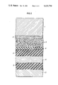
- FIG. 4 is a partial sectional schematic view at an enlarged scale of a portion of the gun barrel wall of the gun barrel illustrated in FIG. 3.
- FIGS. 1 and 2 there is mounted on the exterior wall of the gun barrel 1 with the aid of glueing material 2 two layers of ceramic fibers 3. Over the two layers 3 there is mounted the shrinking hose 4. Over the latter there is mounted a silicone foam layer 5 and over the latter the conically shaped aluminum pipe 6. Over the latter there is mounted the silicone foam layer 9, which is firmly secured to the outer cylindrical aluminum pipe 10. There is disposed between the aluminum pipe 6 and the foam layer 9 a disconnecting point between the inner and outer cover.
- FIG. 1 illustrates the outwardly conically shaped inner cover 12 and the outer cover 11, formed by the layers 9 and 10, which is inwardly conically shaped and which is disposed between a screwable ring 15 of the gun barrel guide bushing 13 and the smoke suction removing device 14.
- the new cover can participate in the "breathing" of the gun barrel during firing and can resist the acceleration forces which occur during firing.
- the layer which is directly applied to the gun barrel must be made out of loose material having a low specific gravity, which is elastically held about the gun barrel by means of the hose made of synthetic material.
- Such an elastic mounting is also achieved by means of the prestressed wound wire which serves as the first heat conducting layer.
Abstract
Description
Claims (11)
Applications Claiming Priority (2)
| Application Number | Priority Date | Filing Date | Title |
|---|---|---|---|
| DE3005117 | 1980-02-12 | ||
| DE19803005117 DE3005117A1 (en) | 1980-02-12 | 1980-02-12 | PROTECTIVE COVER FOR A PROTECTIVE TUBE |
Publications (1)
| Publication Number | Publication Date |
|---|---|
| US4424734A true US4424734A (en) | 1984-01-10 |
Family
ID=6094364
Family Applications (1)
| Application Number | Title | Priority Date | Filing Date |
|---|---|---|---|
| US06/223,945 Expired - Lifetime US4424734A (en) | 1980-02-12 | 1981-01-12 | Protecting cover for a gun barrel |
Country Status (3)
| Country | Link |
|---|---|
| US (1) | US4424734A (en) |
| EP (1) | EP0033770B1 (en) |
| DE (1) | DE3005117A1 (en) |
Cited By (20)
| Publication number | Priority date | Publication date | Assignee | Title |
|---|---|---|---|---|
| EP0183432A1 (en) * | 1984-11-26 | 1986-06-04 | Vickers Plc | Thermal sleeve for gun barrels |
| US4624173A (en) * | 1983-06-21 | 1986-11-25 | Ga Technologies Inc. | Rail gun barrel assembly |
| US4681016A (en) * | 1984-05-02 | 1987-07-21 | Ga Technologies Inc. | Rail gun barrel with gas containment means |
| US4681015A (en) * | 1985-07-17 | 1987-07-21 | Ga Technologies Inc. | Rail gun barrel with axially prestressed insulators |
| US4774872A (en) * | 1983-06-21 | 1988-10-04 | Ga Technologies Inc. | Prestressed tube and tube joint |
| US4840200A (en) * | 1983-06-21 | 1989-06-20 | General Atomics | Prestressed tube |
| US4843946A (en) * | 1984-11-27 | 1989-07-04 | Her Majesty The Queen In Right Of Canada, As Represented By The Minister Of National Defense Of Her Majesty's Canadian Government | Filament-wound venturi |
| US4982648A (en) * | 1986-11-21 | 1991-01-08 | Battelle-Institut E.V. | Gun barrel cooling arrangement |
| US20100051004A1 (en) * | 2008-09-03 | 2010-03-04 | Sheng-Jen Lian | Paintball Gun |
| WO2011022481A1 (en) * | 2009-08-18 | 2011-02-24 | Nemo Equipment, Inc. | Weapon protection device |
| US20110100204A1 (en) * | 2007-11-09 | 2011-05-05 | Gert Schlenkert | Thermal insulation jacket for a gun barrel |
| US20120260901A1 (en) * | 2011-04-14 | 2012-10-18 | George Arthur Proulx | Open railgun with steel barrel sections |
| US8375617B2 (en) | 2009-08-18 | 2013-02-19 | Nemo Equipment, Inc. | Weapon protection device |
| CN105889648A (en) * | 2016-06-07 | 2016-08-24 | 天津市管道工程集团有限公司 | Directly-buried steam heat preservation pipe |
| US9435600B2 (en) * | 2013-10-15 | 2016-09-06 | Oss Suppressors Llc | Thermal mirage reduction accessory for firearms |
| US20170299291A1 (en) * | 2016-02-22 | 2017-10-19 | Radical Firearms, LLC | Handguard and barrel assembly with sound suppressor for a firearm |
| US10302384B1 (en) * | 2017-04-27 | 2019-05-28 | Dbdrop Inc. | Firearm barrel fitment sleeve and method of use |
| US11022396B2 (en) * | 2019-08-18 | 2021-06-01 | Superior Harmonics LLC | Rifle barrel vibration dampener and method of use |
| US11385013B2 (en) | 2016-07-01 | 2022-07-12 | Blackpowder Products, Inc. | Hybrid carbon—steel firearm barrel |
| USD1018757S1 (en) | 2020-09-17 | 2024-03-19 | Blackpowder Products, Inc. | Firearm barrel |
Families Citing this family (10)
| Publication number | Priority date | Publication date | Assignee | Title |
|---|---|---|---|---|
| DE3219124C2 (en) * | 1982-05-21 | 1984-04-19 | Messerschmitt-Bölkow-Blohm GmbH, 8000 München | Gun barrel with protective means against barrel distortion |
| JPS5944597A (en) * | 1982-09-07 | 1984-03-13 | 株式会社富士電機総合研究所 | Gun barrel with heat pipe |
| US4841836A (en) * | 1987-11-02 | 1989-06-27 | Bundy Mark L | Thermal shroud for a gun tube |
| DE19904417C2 (en) | 1999-02-04 | 2002-01-03 | Rheinmetall W & M Gmbh | barrel |
| US7182014B2 (en) | 2002-10-16 | 2007-02-27 | Rescue Academy Inc. | Gun barrel for launching projectiles |
| US6789454B2 (en) * | 2002-10-16 | 2004-09-14 | Rescue Academy Inc. | Gun barrel for launching large projectiles |
| DE102010031898A1 (en) | 2010-07-21 | 2012-01-26 | Rheinmetall Air Defence Ag | Remote controlled, particularly antiaircraft defense gun, comprises component assemblies, such as tower, swash plate, and gun carriage, where insulation is provided, which is embedded at component assemblies |
| US9528785B2 (en) | 2010-07-23 | 2016-12-27 | Ut-Battelle, Llc | Cooling of weapons with graphite foam |
| DE102011106199B3 (en) * | 2011-06-07 | 2012-08-30 | Rheinmetall Air Defence Ag | Apparatus and method for thermal compensation of a weapon barrel |
| WO2014087401A1 (en) * | 2012-12-09 | 2014-06-12 | D.G.L. Us Ltd. | Thermal protecting shroud |
Family Cites Families (5)
| Publication number | Priority date | Publication date | Assignee | Title |
|---|---|---|---|---|
| GB133091A (en) * | 1900-01-01 | |||
| DE83953C (en) * | 1894-11-30 | 1895-12-06 | ||
| DE1918422A1 (en) * | 1969-04-11 | 1970-10-15 | Wegmann & Co | Heat protection cover for cannon |
| US3742640A (en) * | 1971-05-14 | 1973-07-03 | Us Army | Composite firearm barrel |
| DE2917844A1 (en) * | 1979-05-03 | 1980-11-06 | Kabel Metallwerke Ghh | Tube system for carrying cold liquid or gas - has gas absorber in thermal insulation vacuum, esp. for superconducting cable in liq. gas line |
-
1980
- 1980-02-12 DE DE19803005117 patent/DE3005117A1/en active Granted
- 1980-11-29 EP EP80107485A patent/EP0033770B1/en not_active Expired
-
1981
- 1981-01-12 US US06/223,945 patent/US4424734A/en not_active Expired - Lifetime
Cited By (26)
| Publication number | Priority date | Publication date | Assignee | Title |
|---|---|---|---|---|
| US4624173A (en) * | 1983-06-21 | 1986-11-25 | Ga Technologies Inc. | Rail gun barrel assembly |
| US4774872A (en) * | 1983-06-21 | 1988-10-04 | Ga Technologies Inc. | Prestressed tube and tube joint |
| US4840200A (en) * | 1983-06-21 | 1989-06-20 | General Atomics | Prestressed tube |
| US4681016A (en) * | 1984-05-02 | 1987-07-21 | Ga Technologies Inc. | Rail gun barrel with gas containment means |
| EP0183432A1 (en) * | 1984-11-26 | 1986-06-04 | Vickers Plc | Thermal sleeve for gun barrels |
| US4638713A (en) * | 1984-11-26 | 1987-01-27 | Vickers Public Limited Company | Thermal sleeve for gun barrels |
| US4843946A (en) * | 1984-11-27 | 1989-07-04 | Her Majesty The Queen In Right Of Canada, As Represented By The Minister Of National Defense Of Her Majesty's Canadian Government | Filament-wound venturi |
| US4681015A (en) * | 1985-07-17 | 1987-07-21 | Ga Technologies Inc. | Rail gun barrel with axially prestressed insulators |
| US4982648A (en) * | 1986-11-21 | 1991-01-08 | Battelle-Institut E.V. | Gun barrel cooling arrangement |
| US20110100204A1 (en) * | 2007-11-09 | 2011-05-05 | Gert Schlenkert | Thermal insulation jacket for a gun barrel |
| US8347773B2 (en) | 2007-11-09 | 2013-01-08 | Rheinmetall Waffe Munition Gmbh | Thermal insulation jacket for a gun barrel |
| US20100051004A1 (en) * | 2008-09-03 | 2010-03-04 | Sheng-Jen Lian | Paintball Gun |
| WO2011022481A1 (en) * | 2009-08-18 | 2011-02-24 | Nemo Equipment, Inc. | Weapon protection device |
| US20110041376A1 (en) * | 2009-08-18 | 2011-02-24 | Nemo Equipment, Inc. | Weapon protection device |
| US8375617B2 (en) | 2009-08-18 | 2013-02-19 | Nemo Equipment, Inc. | Weapon protection device |
| US20120260901A1 (en) * | 2011-04-14 | 2012-10-18 | George Arthur Proulx | Open railgun with steel barrel sections |
| US8701639B2 (en) * | 2011-04-14 | 2014-04-22 | George Arthur Proulx | Open railgun with steel barrel sections |
| US9435600B2 (en) * | 2013-10-15 | 2016-09-06 | Oss Suppressors Llc | Thermal mirage reduction accessory for firearms |
| US20170299291A1 (en) * | 2016-02-22 | 2017-10-19 | Radical Firearms, LLC | Handguard and barrel assembly with sound suppressor for a firearm |
| CN105889648A (en) * | 2016-06-07 | 2016-08-24 | 天津市管道工程集团有限公司 | Directly-buried steam heat preservation pipe |
| CN105889648B (en) * | 2016-06-07 | 2018-08-28 | 天津市管道工程集团有限公司 | Direct buried steam pipeline |
| US11385013B2 (en) | 2016-07-01 | 2022-07-12 | Blackpowder Products, Inc. | Hybrid carbon—steel firearm barrel |
| US11732988B2 (en) | 2016-07-01 | 2023-08-22 | Blackpowder Products, Inc. | Hybrid carbon—steel firearm barrel |
| US10302384B1 (en) * | 2017-04-27 | 2019-05-28 | Dbdrop Inc. | Firearm barrel fitment sleeve and method of use |
| US11022396B2 (en) * | 2019-08-18 | 2021-06-01 | Superior Harmonics LLC | Rifle barrel vibration dampener and method of use |
| USD1018757S1 (en) | 2020-09-17 | 2024-03-19 | Blackpowder Products, Inc. | Firearm barrel |
Also Published As
| Publication number | Publication date |
|---|---|
| EP0033770A2 (en) | 1981-08-19 |
| EP0033770B1 (en) | 1984-02-15 |
| DE3005117A1 (en) | 1981-08-20 |
| EP0033770A3 (en) | 1981-11-11 |
| DE3005117C2 (en) | 1990-08-09 |
Similar Documents
| Publication | Publication Date | Title |
|---|---|---|
| US4424734A (en) | Protecting cover for a gun barrel | |
| US4841836A (en) | Thermal shroud for a gun tube | |
| US10443446B2 (en) | Steel soft wall fan case | |
| JPS6287800A (en) | Soaking device for gun barrel | |
| KR950700135A (en) | Improvement and Manufacturing Method of Insulated Furnace Roller | |
| KR890001076B1 (en) | Thermal sleeve for gun barrels | |
| JPS6255974B2 (en) | ||
| US3641870A (en) | Shingle-wrap liner for a gun barrel | |
| US20090022579A1 (en) | Burn resistant organic matrix composite material | |
| FI97260B (en) | Optical fiber | |
| US5273603A (en) | Method for manufacturing pressure vessels having holes of different diameters | |
| US5285592A (en) | Motor case with composite overwrap and method | |
| HU176097B (en) | Hydraulic ceiling jack | |
| US4662614A (en) | Blast pipe | |
| GB2103331A (en) | Heat-insulating casing for elongate constructional parts | |
| US6186094B1 (en) | Sabot anti-splitting ring | |
| RU2064600C1 (en) | Method of formation heat-protective coating for solid-propellant rocket engine | |
| CA1175241A (en) | Mechanical and insulating connection between a nozzle and the filament-wound casing of the combustion chamber of a rocket motor | |
| GB2065237A (en) | Turbine blades | |
| CA2008230A1 (en) | Method for thermally insulating a pipeline | |
| US3057148A (en) | Means to improve adherence of lining materials to the inner surface of combustion chambers of rocket motors | |
| RU2018762C1 (en) | Heat-insulated pipe | |
| JPS5564116A (en) | Structure of swirl chamber of internal combustion engine | |
| SE502460C2 (en) | Methods and apparatus for temperature-independent storage | |
| JPS5780016A (en) | Corrosion resisting process utilizing auxiliary metal-tube for connected part of cable |
Legal Events
| Date | Code | Title | Description |
|---|---|---|---|
| AS | Assignment |
Owner name: RHEINMETALL GMBH, GERMANY Free format text: ASSIGNMENT OF ASSIGNORS INTEREST;ASSIGNORS:JANSSEN KARL-EGON;BREUER HEINZ-GUENTER;REEL/FRAME:003846/0490 Effective date: 19810106 |
|
| STCF | Information on status: patent grant |
Free format text: PATENTED CASE |
|
| MAFP | Maintenance fee payment |
Free format text: PAYMENT OF MAINTENANCE FEE, 4TH YEAR, PL 96-517 (ORIGINAL EVENT CODE: M170); ENTITY STATUS OF PATENT OWNER: LARGE ENTITY Year of fee payment: 4 |
|
| MAFP | Maintenance fee payment |
Free format text: PAYMENT OF MAINTENANCE FEE, 8TH YEAR, PL 96-517 (ORIGINAL EVENT CODE: M171); ENTITY STATUS OF PATENT OWNER: LARGE ENTITY Year of fee payment: 8 |
|
| FEPP | Fee payment procedure |
Free format text: PAYOR NUMBER ASSIGNED (ORIGINAL EVENT CODE: ASPN); ENTITY STATUS OF PATENT OWNER: LARGE ENTITY |
|
| MAFP | Maintenance fee payment |
Free format text: PAYMENT OF MAINTENANCE FEE, 12TH YEAR, LARGE ENTITY (ORIGINAL EVENT CODE: M185); ENTITY STATUS OF PATENT OWNER: LARGE ENTITY Year of fee payment: 12 |