US4457523A - Torsionally flexible metallic annular seal - Google Patents
Torsionally flexible metallic annular seal Download PDFInfo
- Publication number
- US4457523A US4457523A US06/437,869 US43786982A US4457523A US 4457523 A US4457523 A US 4457523A US 43786982 A US43786982 A US 43786982A US 4457523 A US4457523 A US 4457523A
- Authority
- US
- United States
- Prior art keywords
- sealing
- annular
- central
- section
- sealing ring
- Prior art date
- Legal status (The legal status is an assumption and is not a legal conclusion. Google has not performed a legal analysis and makes no representation as to the accuracy of the status listed.)
- Expired - Lifetime
Links
Images


Classifications
-
- F—MECHANICAL ENGINEERING; LIGHTING; HEATING; WEAPONS; BLASTING
- F16—ENGINEERING ELEMENTS AND UNITS; GENERAL MEASURES FOR PRODUCING AND MAINTAINING EFFECTIVE FUNCTIONING OF MACHINES OR INSTALLATIONS; THERMAL INSULATION IN GENERAL
- F16J—PISTONS; CYLINDERS; SEALINGS
- F16J15/00—Sealings
- F16J15/02—Sealings between relatively-stationary surfaces
- F16J15/021—Sealings between relatively-stationary surfaces with elastic packing
-
- F—MECHANICAL ENGINEERING; LIGHTING; HEATING; WEAPONS; BLASTING
- F16—ENGINEERING ELEMENTS AND UNITS; GENERAL MEASURES FOR PRODUCING AND MAINTAINING EFFECTIVE FUNCTIONING OF MACHINES OR INSTALLATIONS; THERMAL INSULATION IN GENERAL
- F16J—PISTONS; CYLINDERS; SEALINGS
- F16J15/00—Sealings
- F16J15/02—Sealings between relatively-stationary surfaces
- F16J15/06—Sealings between relatively-stationary surfaces with solid packing compressed between sealing surfaces
- F16J15/08—Sealings between relatively-stationary surfaces with solid packing compressed between sealing surfaces with exclusively metal packing
- F16J15/0887—Sealings between relatively-stationary surfaces with solid packing compressed between sealing surfaces with exclusively metal packing the sealing effect being obtained by elastic deformation of the packing
-
- F—MECHANICAL ENGINEERING; LIGHTING; HEATING; WEAPONS; BLASTING
- F16—ENGINEERING ELEMENTS AND UNITS; GENERAL MEASURES FOR PRODUCING AND MAINTAINING EFFECTIVE FUNCTIONING OF MACHINES OR INSTALLATIONS; THERMAL INSULATION IN GENERAL
- F16L—PIPES; JOINTS OR FITTINGS FOR PIPES; SUPPORTS FOR PIPES, CABLES OR PROTECTIVE TUBING; MEANS FOR THERMAL INSULATION IN GENERAL
- F16L21/00—Joints with sleeve or socket
- F16L21/02—Joints with sleeve or socket with elastic sealing rings between pipe and sleeve or between pipe and socket, e.g. with rolling or other prefabricated profiled rings
Definitions
- the invention relates to a torsionally flexible annular seal formed as a metallic, resilient sealing ring for a pair of concentric, hollow annular bodies having high pressure and temperature fluid flowing therethrough.
- the sealing ring includes a central tapering portion, a first curvilinear sealing portion at one end of the central portion, and a second curvilinear sealing portion at the other end of the central portion.
- the sealing ring is especially useful in turbine engine assemblies between concentric, hollow annular bodies that thermally expand at different rates and are exposed to temperatures up to about 1400° F. and pressures of 400-500 psi.
- Resilient, metallic sealing rings are well known in the art for sealing between a pair of coupled concentric, hollow annular bodies having high temperature and pressure fluid flowing therethrough. These sealing rings have numerous configurations, usually depending upon the cavity to be sealed. While these seals are effective in many situations, a need has long existed for a resilient metallic sealing ring capable of maintaining a tight seal between two cylindrical surfaces that expand at different rates, due to differences in their temperatures or in their coefficients of thermal expansion.
- the basic problem with providing such a seal is that the expansion of the cylindrical surfaces tends to compress the seal beyond its elastic range and thus the seal does not recover to a sealing configuration once the expansion cycle is completed. In other words, the cross sectional width of the sealing ring is permanently decreased, thereby causing leakage to commence almost as soon as the differentially expanded cylindrical surfaces begin to return to their original dimensions. This is usually caused by significant bending deflections in the seals.
- a primary object of the invention is to provide a torsionally flexible annular seal in the form of a metallic, resilient sealing ring that is capable of establishing and maintaining an effective seal between a pair of annular bodies having high pressure and temperature fluid flowing therethrough and that have different rates of thermal expansion.
- Another object of the invention is to provide such a metallic resilient sealing ring that can maintain its sealing capability during axial displacement of the annular bodies.
- Another object of the invention is to provide such a metallic resilient sealing ring that absorbs radial expansion and contraction of adjacent annular bodies in the elastic range by means of a rotational deflection, not a bending deflection and seals along circular sealing lines in different planes.
- a resilient, metallic sealing ring comprising a central tapering annular portion having first and second ends; a first annular sealing portion extending from the first end of the central portion and being curvilinear in cross section; and a second annular sealing portion extending from the second end of the central portion and being curvilinear in cross section.
- first and second sealing portions are substantially semi-circular in cross section, the central portion is upwardly and inwardly tapering from the second end to the first end, and the first and second sealing portions extend radially inwardly of the central portion.
- the sealing ring central portion is frustoconical and tapers at an angle of about 60° before installation and at about 75° when preloaded and installed.
- the central portion comprises a concave portion extending from the second sealing portion and a convex portion extending from the first sealing portion.
- first and second sealing portions extending from the tapering central portion, seal against inner and outer cylindrical surfaces defined by the pair of concentric, annular bodies, this sealing including at least two circular sealing lines in different planes.
- FIG. 1 is a top plan view in longitudinal section of a sealing assembly in accordance with the invention including the metallic, resilient sealing ring in a sealing position between inner and outer cylindrical surfaces defined by a pair of annular bodies;
- FIG. 2 is a view similar to that shown in FIG. 1 except that a pressure thrust by the fluid flowing through the annular bodies has moved the sealing ring into contact with an axially facing annular surface extending from the inner cylindrical surface;
- FIG. 3 is a partially exploded view similar to that shown in FIG. 1 showing the sealing ring installed on the inner body and about to be received in the outer body, the sealing ring being in an unloaded condition;
- FIG. 4 is a top plan view in longitudinal section of the sealing ring shown in FIGS. 1-3 in its unloaded, rest condition;
- FIG. 5 is a front elevational view of the sealing ring shown in FIG. 4;
- FIG. 6 is a top plan view in longitudinal section of a modified sealing ring having a central portion with a convex portion and a concave portion;
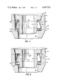
- FIG. 7 is a top plan view in longitudinal section of the sealing ring of FIG. 6 installed between the two annular bodies but not yet exposed to a pressure thrust;
- FIG. 8 is a view similar to that shown in FIG. 7 except that the sealing ring has been exposed to a pressure thrust, thereby moving the ring into engagement with the axially facing surface extending from the inner cylindrical surface and in addition moving the convex portion of the central portion into sealing engagement with the outer cylindrical surface.
- a sealing assembly 10 in accordance with the invention includes a metallic, resilient sealing ring 12 for use in sealing against a first cylindrical surface 14 on the inner surface of a first outer hollow annular body 16 and a second concentric cylindrical surface 18 on the outer surface of a second inner hollow annular body 20.
- the sealing ring 12 cross section is torsionally deflected from a condition shown in FIG. 3 to the preloaded condition shown in FIGS. 1 and 2 so that it can torsionally deflect in either direction of torsional rotation upon thermal expansion of the first and second bodies. This is accomplished because the sealing portions seal in different planes, as described hereinafter.
- the first outer annular body 16 is tubular and includes above radially inwardly facing cylindrical inner surface 14 a downwardly and inwardly tapering frustoconical surface 22 that tapers at about 6° 30'. This taper is an assembly aid and could be up to about 15° as desired.
- Below inner cylindrical surface 14 is a curved annular surface 25 that extends into an axially facing annular surface 26 which in turn extends into a downwardly and inwardly tapering frustoconical surface 27.
- This frustoconical surface tapers at an angle substantially equal to the angle of taper of frustoconical surface 22.
- Frustoconical surface 27 extends into an inwardly facing cylindrical surface 28 through which the high temperature and pressure fluid flows.
- the second inner body 20 below the radially outwardly facing cylindrical surface 18 has a downwardly and inwardly tapering frustoconical surface 31 leading to an annular axially facing surface 32.
- Above the cylindrical surface 18 is an axially facing annular surface 34 extending at right angles to surface 18.
- Above surface 34 is a downwardly and inwardly tapering frustoconical surface 35 which leads into an outwardly facing cylindrical surface 36.
- the second body 20 is hollow with a flow-through end defined by annular surface 32 so that the high pressure and temperature fluid flowing along the first body 16 can pass through the sealing assembly 10 and then into the second body 20.
- the frustoconical surface 31 tapers at an angle of about 15°.
- the first and second bodies are connected together once the sealing ring 12 is installed in any conventional fashion which allows relative axial movement due to thermal expansion, but not enough to axially crush ring 12.
- the sealing ring 12 as shown in FIGS. 3, 4 and 5, comprises a central tapering portion 42 having a first end 43 and a second end 44, a first annular sealing portion 46 extending from the first end of the central portion and terminating in a free annular edge, and a second annular sealing portion 47 extending from the second end of the central portion and terminating in a free annular edge.
- Each of these sealing portions is curvilinear in cross section, this cross section being arcuate and substantially semi-circular.
- the overall cross section of the ring including the two sealing portions and the central portion is substantially C-shaped.
- the sealing portions each extend radially inwardly of the central portion 42.
- This central portion is upwardly and inwardly tapering from the second end 44 to the first end 43 and is frustoconical, the taper being shown as about 60° in FIG. 4, although the angle of taper can vary depending upon the size of the cavity receiving the ring and the potential expansion of the annular bodies.
- the diameter of the first sealing portion 46 is smaller than the diameter of the second sealing portion 47, with this first sealing portion intended to sealingly engage the outwardly facing cylindrical surface 18 on the inner second body and with the second sealing portion 47 intended to sealingly engage the inwardly facing cylindrical surface 14 on the first body 16, as seen in FIGS. 1-3.
- the central portion and two sealing portions of the sealing ring are integrally formed from a precipitation hardened high temperature alloy such as Waspaloy or Inconel.
- the outer diameter of the sealing ring 12 is 9.130-9.135 inches, the inner diameter is 8.740-8.745 inches, the height is 0.400 inch and the thickness of the material is 0.010 inch.
- the radius of curvature of the first and second sealing portions 46 and 47 on the ring is about 0.063 inch.
- the diameter of the inwardly facing cylindrical surface 14 on the first body is 9.115-9.120 inches and the diameter of the outwardly facing cylindrical surface 18 on the second body is 8.755-8.760 inches.
- the radius of curvature of curved annular surface 25 is 0.040-0.060 inch and the axial length of cylindrical surface 14 is a minimum of 0.555 inch.
- a wear resistant coating is advantageously applied to the sealing ring or the cylindrical surfaces 14 and 18.
- One such suitable combination for applications at about 1,000° F. is a coating of Tribaloy 800 on the sealing ring and a coating of Tribaloy 700 on the cylindrical surfaces 14 and 18.
- the sealing ring can be coated with Tribaloy 800 and the material forming the first and second bodies in the area of cylindrical surfaces 14 and 18 can be Incoloy 913.
- the sealing assembly can advantageously be used at temperatures up to 1400° F. and pressures of 400-500 psi.
- the sealing ring 12 is first received on the cylindrical surface 18 on the second body 20 with an interference fit of about 0.010-0.020 inch shown in FIG. 3. Then, the first body 16 is moved axially towards the second body so that the second sealing portion 47 on the sealing ring engages frustoconical surface 22 on the first body. Continued axial movement of the first body towards the second body will cause the sealing ring to be radially inwardly deflected into a preload condition until the second sealing portion 47 is fully received in the cylindrical surface 14 of the first body, as seen in FIG. 1.
- any thermal expansion or slight axial displacement of the first and second bodies will result in a maintenance of the sealing thereof by sealing ring 12 due to its preload and torsionally or rotational deflection capability.
- the bending rigidity of the sealing portions is greater than the torsional rigidity of the central portion, so the expansion of the bodies is reflected in a torsional deflection of the central portion rather than bending of the sealing portions since the sealing portions are in different planes.
- interference fit mentioned above regarding surface 18 and ring 12 is by way of example only since the interference fit must be adjusted in specific cases to allow for the different expansion rates of the specific materials used.
- FIGS. 6-8 a second embodiment of the invention is illustrated where the configurations of the first and second bodies 16 and 20 are the same but the configuration of the sealing ring 12' is different. Accordingly, the reference numerals used with regard to the first and second bodies above regarding FIGS. 1-5 remain the same.
- the sealing ring 12' comprises a central tapering portion 42' having first and second ends 43' and 44', a first sealing portion 46' extending from the first end and a second sealing portion 47' extending from the second end.
- This structure is similar to that described above regarding sealing ring 12.
- the central tapering portion 42' has a concave portion 54 extending from the second sealing portion 47' and a convex portion 55 extending from the first sealing portion 46', these concave and convex portions extending into each other near the middle of the central portion.
- sealing ring 12' The assembly and operation of the sealing ring 12' is similar to that described above regarding sealing ring 12, except that sealing ring 12' is more suitable to higher pressure environments.
- a primary sealing line 49' shown in phantom
- a second primary circular sealing line 50' is established between engagement of the second sealing portion 47' and the inwardly facing cylindrical surface 14.
- the convex portion 55 on the sealing ring 12' is lightly touching or slightly spaced away from cylindrical surface 14.
- the sealing ring 12' upon conduction of high pressure and temperature fluid through the first and second bodies 16 and 20, the sealing ring 12' will move axially to a position seen in FIG. 8.
- the primary circular sealing lines 49' and 50' have been upwardly displaced and in addition a secondary circular sealing line 51' has been established between the upper surface of the first sealing portion 46' and the axially facing annular surface 34.
- a second secondary circular sealing line 52' has been established between the outwardly facing and now outwardly deflected convex portion 55 of the sealing ring and the inwardly facing cylindrical surface 14 of the first body 16. The addition of this sealing line adds to the sealing capability of the sealing ring 12'.
Abstract
Description
Claims (25)
Priority Applications (3)
| Application Number | Priority Date | Filing Date | Title |
|---|---|---|---|
| US06/437,869 US4457523A (en) | 1982-10-29 | 1982-10-29 | Torsionally flexible metallic annular seal |
| GB08322735A GB2129505B (en) | 1982-10-29 | 1983-08-24 | A torsionally flexible annular seal |
| FR8316060A FR2535429B1 (en) | 1982-10-29 | 1983-10-10 | ELASTIC SEALING RING |
Applications Claiming Priority (1)
| Application Number | Priority Date | Filing Date | Title |
|---|---|---|---|
| US06/437,869 US4457523A (en) | 1982-10-29 | 1982-10-29 | Torsionally flexible metallic annular seal |
Publications (1)
| Publication Number | Publication Date |
|---|---|
| US4457523A true US4457523A (en) | 1984-07-03 |
Family
ID=23738267
Family Applications (1)
| Application Number | Title | Priority Date | Filing Date |
|---|---|---|---|
| US06/437,869 Expired - Lifetime US4457523A (en) | 1982-10-29 | 1982-10-29 | Torsionally flexible metallic annular seal |
Country Status (3)
| Country | Link |
|---|---|
| US (1) | US4457523A (en) |
| FR (1) | FR2535429B1 (en) |
| GB (1) | GB2129505B (en) |
Cited By (38)
| Publication number | Priority date | Publication date | Assignee | Title |
|---|---|---|---|---|
| US4779901A (en) * | 1983-12-29 | 1988-10-25 | Eg&G Pressure Science, Inc. | Sealed rigid pipe joint |
| US4813692A (en) * | 1987-01-22 | 1989-03-21 | Eg&G Pressure Science, Inc. | Pressure balanced S-seal |
| US4817668A (en) * | 1987-10-02 | 1989-04-04 | National Coupling Company, Inc. | Integral metal seal for hydraulic coupling |
| US4854600A (en) * | 1987-01-22 | 1989-08-08 | Eg&G Pressure Science, Inc. | Pressure balanced metallic S-seal |
| US5158305A (en) * | 1992-01-31 | 1992-10-27 | Eg&G Pressure Science, Inc. | Pressure-energized two-element seal |
| US5249814A (en) * | 1992-01-31 | 1993-10-05 | Eg&G Pressure Science, Inc. | Multi-ply sealing rings and methods for manufacturing same |
| US5433456A (en) * | 1992-12-18 | 1995-07-18 | The Advanced Products Company | Spring energized convoluted surface seal |
| US5433370A (en) * | 1993-01-14 | 1995-07-18 | Eg&G Pressure Science, Inc. | Multi-ply sealing rings and methods for manufacturing same |
| US5639100A (en) * | 1993-01-07 | 1997-06-17 | Ksb Aktiengesellschaft | Metal gasket |
| FR2758377A1 (en) * | 1997-01-13 | 1998-07-17 | Eg & G Pressure Science Inc | COAXIAL SEALING RING |
| WO1998058197A1 (en) * | 1997-06-13 | 1998-12-23 | Yuping Jiao | Flexible-plastic metallic seal |
| US6155573A (en) * | 1998-06-10 | 2000-12-05 | Skf Usa Inc. | Removable and replaceable hub seal |
| GB2382851A (en) * | 2001-12-07 | 2003-06-11 | Perkinelmer Inc | Annular metallic seal |
| US20040056431A1 (en) * | 2002-09-24 | 2004-03-25 | Honda Giken Kogyo Kabushiki Kaisha | Insertable gasket and inserting structure |
| US20040130149A1 (en) * | 2002-10-17 | 2004-07-08 | Jason Gilmore | Flexible coupling |
| US20050023769A1 (en) * | 2003-07-29 | 2005-02-03 | Halling Horace P. | Metallic seal |
| US20050023770A1 (en) * | 2003-07-31 | 2005-02-03 | Swensen Jeffrey E. | Pressure energized metallic seal |
| US20050082832A1 (en) * | 2003-10-20 | 2005-04-21 | Smith Robert E.Iii | Seal retainer with metal seal members for undersea hydraulic coupling |
| US20050082764A1 (en) * | 2003-10-20 | 2005-04-21 | Smith Robert E.Iii | Seal retainer with pressure energized metal seal members for undersea hydraulic coupling |
| WO2006085853A1 (en) * | 2005-01-28 | 2006-08-17 | American Seal And Engineering Company, Inc. | Resilient seal |
| US20070235948A1 (en) * | 2003-07-29 | 2007-10-11 | Halling Horace P | Metallic seal |
| US20090056223A1 (en) * | 2007-09-04 | 2009-03-05 | Patel Sunilkant A | Quench ring rim and methods for fabricating |
| US20100244431A1 (en) * | 2009-03-27 | 2010-09-30 | National Coupling Company, Inc. | Hydraulic coupling member with bidirectional pressure-energized probe seal |
| US20110057395A1 (en) * | 2006-11-17 | 2011-03-10 | Petrowell Ltd. | Seal element |
| US20110089266A1 (en) * | 2009-10-16 | 2011-04-21 | General Electric Company | Fuel nozzle lip seals |
| US20110233876A1 (en) * | 2010-03-25 | 2011-09-29 | Bergman Russell J | Turbine sealing system |
| US20130207349A1 (en) * | 2012-02-09 | 2013-08-15 | Cameron International Corporation | Lip Seal |
| US20140361493A1 (en) * | 2013-06-11 | 2014-12-11 | Delavan Inc | Sealing device |
| US20150167557A1 (en) * | 2013-12-17 | 2015-06-18 | Rolls-Royce Corporation | Seal for gas turbine engines |
| US20150330253A1 (en) * | 2012-02-20 | 2015-11-19 | Borgwarner Inc. | Bearing housing of an exhaust-gas turbocharger |
| US20160090941A1 (en) * | 2013-06-07 | 2016-03-31 | Reinz-Dichtungs-Gmbh | Sealing system |
| US10309562B2 (en) | 2017-07-18 | 2019-06-04 | Freudenberg Oil & Gas, Llc | Metal to metal wedge ring seal |
| US10436326B2 (en) * | 2016-08-15 | 2019-10-08 | Festo Ag & Co. Kg | Sealing system and a valve provided therewith |
| US10480337B2 (en) | 2017-04-18 | 2019-11-19 | Rolls-Royce North American Technologies Inc. | Turbine shroud assembly with multi-piece seals |
| US10550976B2 (en) * | 2014-06-06 | 2020-02-04 | Jiangsu Beite Pipe Fittings Co., Ltd. | High-pressure tolerant integrated leakage-proof sleeve compensator |
| US10746037B2 (en) | 2016-11-30 | 2020-08-18 | Rolls-Royce Corporation | Turbine shroud assembly with tandem seals |
| US11473437B2 (en) * | 2015-09-24 | 2022-10-18 | General Electric Company | Turbine snap in spring seal |
| US11598423B2 (en) | 2019-12-27 | 2023-03-07 | Saint-Gobain Performance Plastics Corporation | Dynamic seal |
Families Citing this family (4)
| Publication number | Priority date | Publication date | Assignee | Title |
|---|---|---|---|---|
| AU4160885A (en) * | 1984-04-25 | 1985-10-31 | Kimberly-Clark Corporation | Die seal |
| GB2250324A (en) * | 1990-11-05 | 1992-06-03 | Nicholson Seals Ltd | Seal |
| DE19648900A1 (en) * | 1996-11-26 | 1998-05-28 | Bosch Gmbh Robert | Radial sealing ring and process for its manufacture |
| US20080290602A1 (en) * | 2007-05-21 | 2008-11-27 | Baker Hughes Incorporated | Self energizing seal element |
Citations (23)
| Publication number | Priority date | Publication date | Assignee | Title |
|---|---|---|---|---|
| GB444217A (en) * | 1934-12-31 | 1936-03-17 | English Steel Corp Ltd | Improvements in or relating to pipe and like joints |
| US2452469A (en) * | 1945-05-22 | 1948-10-26 | James P Johnson | Seal |
| US2774618A (en) * | 1954-09-13 | 1956-12-18 | Winston T Alderson | Combination ball and slip joint for pipes |
| GB805350A (en) * | 1956-07-18 | 1958-12-03 | New York Air Brake Co | Metallic sealing ring and joint employing such ring |
| US3192690A (en) * | 1963-01-03 | 1965-07-06 | Dudley D Taylor | Sealing ring with e-shaped radial section |
| US3285632A (en) * | 1964-03-09 | 1966-11-15 | Johns Manville | Conduit joint construction |
| US3490777A (en) * | 1967-04-13 | 1970-01-20 | John O Emmerson | Metal seal construction |
| US3561793A (en) * | 1969-09-03 | 1971-02-09 | Temper Corp | Seal element and spacer member for use therewith |
| US3575432A (en) * | 1969-10-08 | 1971-04-20 | Pressure Science Inc | Sealing ring |
| DE2121731A1 (en) * | 1971-05-03 | 1972-11-23 | Stephan, Herbert, 6241 Oberreifenberg | Concrete expansion joint seal - comprises flexible stri and poured sealing material |
| US3751048A (en) * | 1972-06-02 | 1973-08-07 | Temper Corp | Seal element |
| US3761102A (en) * | 1970-07-17 | 1973-09-25 | Corrugated Packing Sheet Metal | Sealing means |
| US3797836A (en) * | 1971-09-07 | 1974-03-19 | Pressure Science Inc | Sealing ring |
| US3857572A (en) * | 1973-10-18 | 1974-12-31 | Pressure Science Inc | E-ring seal assembly |
| US3869132A (en) * | 1973-07-18 | 1975-03-04 | Pressure Science Inc | Fire resistant sealing ring combination |
| US4054306A (en) * | 1976-05-28 | 1977-10-18 | Pressure Science Incorporated | Tube and cylindrical surface sealing apparatus |
| US4121843A (en) * | 1977-10-04 | 1978-10-24 | Pressure Science, Incorporated | Multiple convolution sealing ring |
| DE2909223A1 (en) * | 1978-03-30 | 1979-10-04 | Balzers Hochvakuum | SEALING DEVICE FOR VACUUM CONNECTIONS |
| DE2815075A1 (en) * | 1978-04-07 | 1979-10-18 | Autogenwerk Rhoena Gmbh | Dial pressure gauge union seal - has hollow truncated cone section to provide centering action whilst screwing gauge home |
| US4199151A (en) * | 1978-08-14 | 1980-04-22 | General Electric Company | Method and apparatus for retaining seals |
| US4218067A (en) * | 1979-02-02 | 1980-08-19 | Pressure Science Incorporated | Multi-ply sealing rings |
| US4281841A (en) * | 1978-03-30 | 1981-08-04 | The United States Of America As Represented By The United States Department Of Energy | O-Ring sealing arrangements for ultra-high vacuum systems |
| US4336943A (en) * | 1980-11-14 | 1982-06-29 | United Technologies Corporation | Wedge-shaped seal for flanged joints |
Family Cites Families (4)
| Publication number | Priority date | Publication date | Assignee | Title |
|---|---|---|---|---|
| DE1075909B (en) * | 1956-07-18 | 1960-02-18 | New York Air Brake Co | Annular elastic sealing member |
| GB1360951A (en) * | 1972-04-14 | 1974-07-24 | Corrugated Packing Sheet Metal | Sealing means |
| US4125929A (en) * | 1974-03-04 | 1978-11-21 | Temper Corporation | Deformable metallic element |
| US4168839A (en) * | 1977-03-18 | 1979-09-25 | Harold P. Hopp | Means and method for installing captive type spark plug gaskets |
-
1982
- 1982-10-29 US US06/437,869 patent/US4457523A/en not_active Expired - Lifetime
-
1983
- 1983-08-24 GB GB08322735A patent/GB2129505B/en not_active Expired
- 1983-10-10 FR FR8316060A patent/FR2535429B1/en not_active Expired
Patent Citations (23)
| Publication number | Priority date | Publication date | Assignee | Title |
|---|---|---|---|---|
| GB444217A (en) * | 1934-12-31 | 1936-03-17 | English Steel Corp Ltd | Improvements in or relating to pipe and like joints |
| US2452469A (en) * | 1945-05-22 | 1948-10-26 | James P Johnson | Seal |
| US2774618A (en) * | 1954-09-13 | 1956-12-18 | Winston T Alderson | Combination ball and slip joint for pipes |
| GB805350A (en) * | 1956-07-18 | 1958-12-03 | New York Air Brake Co | Metallic sealing ring and joint employing such ring |
| US3192690A (en) * | 1963-01-03 | 1965-07-06 | Dudley D Taylor | Sealing ring with e-shaped radial section |
| US3285632A (en) * | 1964-03-09 | 1966-11-15 | Johns Manville | Conduit joint construction |
| US3490777A (en) * | 1967-04-13 | 1970-01-20 | John O Emmerson | Metal seal construction |
| US3561793A (en) * | 1969-09-03 | 1971-02-09 | Temper Corp | Seal element and spacer member for use therewith |
| US3575432A (en) * | 1969-10-08 | 1971-04-20 | Pressure Science Inc | Sealing ring |
| US3761102A (en) * | 1970-07-17 | 1973-09-25 | Corrugated Packing Sheet Metal | Sealing means |
| DE2121731A1 (en) * | 1971-05-03 | 1972-11-23 | Stephan, Herbert, 6241 Oberreifenberg | Concrete expansion joint seal - comprises flexible stri and poured sealing material |
| US3797836A (en) * | 1971-09-07 | 1974-03-19 | Pressure Science Inc | Sealing ring |
| US3751048A (en) * | 1972-06-02 | 1973-08-07 | Temper Corp | Seal element |
| US3869132A (en) * | 1973-07-18 | 1975-03-04 | Pressure Science Inc | Fire resistant sealing ring combination |
| US3857572A (en) * | 1973-10-18 | 1974-12-31 | Pressure Science Inc | E-ring seal assembly |
| US4054306A (en) * | 1976-05-28 | 1977-10-18 | Pressure Science Incorporated | Tube and cylindrical surface sealing apparatus |
| US4121843A (en) * | 1977-10-04 | 1978-10-24 | Pressure Science, Incorporated | Multiple convolution sealing ring |
| DE2909223A1 (en) * | 1978-03-30 | 1979-10-04 | Balzers Hochvakuum | SEALING DEVICE FOR VACUUM CONNECTIONS |
| US4281841A (en) * | 1978-03-30 | 1981-08-04 | The United States Of America As Represented By The United States Department Of Energy | O-Ring sealing arrangements for ultra-high vacuum systems |
| DE2815075A1 (en) * | 1978-04-07 | 1979-10-18 | Autogenwerk Rhoena Gmbh | Dial pressure gauge union seal - has hollow truncated cone section to provide centering action whilst screwing gauge home |
| US4199151A (en) * | 1978-08-14 | 1980-04-22 | General Electric Company | Method and apparatus for retaining seals |
| US4218067A (en) * | 1979-02-02 | 1980-08-19 | Pressure Science Incorporated | Multi-ply sealing rings |
| US4336943A (en) * | 1980-11-14 | 1982-06-29 | United Technologies Corporation | Wedge-shaped seal for flanged joints |
Cited By (65)
| Publication number | Priority date | Publication date | Assignee | Title |
|---|---|---|---|---|
| US4779901A (en) * | 1983-12-29 | 1988-10-25 | Eg&G Pressure Science, Inc. | Sealed rigid pipe joint |
| US4813692A (en) * | 1987-01-22 | 1989-03-21 | Eg&G Pressure Science, Inc. | Pressure balanced S-seal |
| US4854600A (en) * | 1987-01-22 | 1989-08-08 | Eg&G Pressure Science, Inc. | Pressure balanced metallic S-seal |
| US4817668A (en) * | 1987-10-02 | 1989-04-04 | National Coupling Company, Inc. | Integral metal seal for hydraulic coupling |
| US5158305A (en) * | 1992-01-31 | 1992-10-27 | Eg&G Pressure Science, Inc. | Pressure-energized two-element seal |
| US5249814A (en) * | 1992-01-31 | 1993-10-05 | Eg&G Pressure Science, Inc. | Multi-ply sealing rings and methods for manufacturing same |
| US5433456A (en) * | 1992-12-18 | 1995-07-18 | The Advanced Products Company | Spring energized convoluted surface seal |
| US5639100A (en) * | 1993-01-07 | 1997-06-17 | Ksb Aktiengesellschaft | Metal gasket |
| US5433370A (en) * | 1993-01-14 | 1995-07-18 | Eg&G Pressure Science, Inc. | Multi-ply sealing rings and methods for manufacturing same |
| FR2758377A1 (en) * | 1997-01-13 | 1998-07-17 | Eg & G Pressure Science Inc | COAXIAL SEALING RING |
| US5799954A (en) * | 1997-01-13 | 1998-09-01 | Eg&G Pressure Science, Inc. | Coaxial sealing ring |
| WO1998058197A1 (en) * | 1997-06-13 | 1998-12-23 | Yuping Jiao | Flexible-plastic metallic seal |
| CN1064749C (en) * | 1997-06-13 | 2001-04-18 | 焦予平 | Elasticity and plasticity metal sealing device |
| US6155573A (en) * | 1998-06-10 | 2000-12-05 | Skf Usa Inc. | Removable and replaceable hub seal |
| US7004478B2 (en) | 2001-12-07 | 2006-02-28 | Perkinelmer Inc. | Shallow metallic s-seal |
| GB2382851B (en) * | 2001-12-07 | 2005-08-10 | Perkinelmer Inc | Shallow metallic S-seal |
| GB2382851A (en) * | 2001-12-07 | 2003-06-11 | Perkinelmer Inc | Annular metallic seal |
| US20040056431A1 (en) * | 2002-09-24 | 2004-03-25 | Honda Giken Kogyo Kabushiki Kaisha | Insertable gasket and inserting structure |
| EP1403573A1 (en) * | 2002-09-24 | 2004-03-31 | Honda Giken Kogyo Kabushiki Kaisha | Insertable gasket and inserting structure |
| US6860487B2 (en) | 2002-09-24 | 2005-03-01 | Honda Giken Kogyo Kabushiki Kaisha | Insertable gasket and inserting structure |
| US20040130149A1 (en) * | 2002-10-17 | 2004-07-08 | Jason Gilmore | Flexible coupling |
| US6983940B2 (en) | 2003-07-29 | 2006-01-10 | American Seal And Engineering Company, Inc. | Metallic seal |
| US7789397B2 (en) * | 2003-07-29 | 2010-09-07 | American Seal And Engineering Company, Inc. | Metallic seal |
| US20070235948A1 (en) * | 2003-07-29 | 2007-10-11 | Halling Horace P | Metallic seal |
| US20050023769A1 (en) * | 2003-07-29 | 2005-02-03 | Halling Horace P. | Metallic seal |
| US20050023770A1 (en) * | 2003-07-31 | 2005-02-03 | Swensen Jeffrey E. | Pressure energized metallic seal |
| US20060168807A1 (en) * | 2003-07-31 | 2006-08-03 | Perkinelmer, Inc. | Pressure energized metallic seal |
| US7866040B2 (en) | 2003-07-31 | 2011-01-11 | Eaton Corporation | Pressure energized metallic seal |
| US7100925B2 (en) * | 2003-07-31 | 2006-09-05 | Perkin Elmer, Inc. | Pressure energized metallic seal |
| US20050082832A1 (en) * | 2003-10-20 | 2005-04-21 | Smith Robert E.Iii | Seal retainer with metal seal members for undersea hydraulic coupling |
| US20050082764A1 (en) * | 2003-10-20 | 2005-04-21 | Smith Robert E.Iii | Seal retainer with pressure energized metal seal members for undersea hydraulic coupling |
| US7021677B2 (en) | 2003-10-20 | 2006-04-04 | National Coupling Company, Inc. | Seal retainer with metal seal members for undersea hydraulic coupling |
| US7303194B2 (en) | 2003-10-20 | 2007-12-04 | National Coupling Company, Inc. | Seal retainer with pressure energized metal seal members for undersea hydraulic coupling |
| US20080224422A1 (en) * | 2005-01-28 | 2008-09-18 | American Seal And Engineering Company, Inc. | Resilient Seal |
| WO2006085853A1 (en) * | 2005-01-28 | 2006-08-17 | American Seal And Engineering Company, Inc. | Resilient seal |
| EP3073164A1 (en) | 2005-01-28 | 2016-09-28 | American Seal and Engineering Company, Inc. | Resilient seal |
| EP3591275A1 (en) | 2005-01-28 | 2020-01-08 | American Seal and Engineering Company, Inc. | Resilient seal |
| US20150053395A1 (en) * | 2006-11-17 | 2015-02-26 | Petrowell Limited | Seal Element |
| US20110057395A1 (en) * | 2006-11-17 | 2011-03-10 | Petrowell Ltd. | Seal element |
| US9915120B2 (en) * | 2006-11-17 | 2018-03-13 | Weatherford Technology Holdings, Llc | Seal element |
| US20090056223A1 (en) * | 2007-09-04 | 2009-03-05 | Patel Sunilkant A | Quench ring rim and methods for fabricating |
| US20100244431A1 (en) * | 2009-03-27 | 2010-09-30 | National Coupling Company, Inc. | Hydraulic coupling member with bidirectional pressure-energized probe seal |
| DE102009021696B4 (en) * | 2009-03-27 | 2016-09-29 | National Coupling Co., Inc. | Hydraulic coupling element with bidirectional pressure-fed header gasket |
| US8087700B2 (en) * | 2009-03-27 | 2012-01-03 | National Coupling Company, Inc. | Hydraulic coupling member with bidirectional pressure-energized probe seal |
| US20110089266A1 (en) * | 2009-10-16 | 2011-04-21 | General Electric Company | Fuel nozzle lip seals |
| CN102042595A (en) * | 2009-10-16 | 2011-05-04 | 通用电气公司 | Fuel nozzle lip seals |
| US8794640B2 (en) | 2010-03-25 | 2014-08-05 | United Technologies Corporation | Turbine sealing system |
| US20110233876A1 (en) * | 2010-03-25 | 2011-09-29 | Bergman Russell J | Turbine sealing system |
| US20130207349A1 (en) * | 2012-02-09 | 2013-08-15 | Cameron International Corporation | Lip Seal |
| US9611712B2 (en) * | 2012-02-09 | 2017-04-04 | Onesubsea Ip Uk Limited | Lip seal |
| US11415024B2 (en) * | 2012-02-20 | 2022-08-16 | Borgwarner Inc. | Bearing housing of an exhaust-gas turbocharger |
| US20150330253A1 (en) * | 2012-02-20 | 2015-11-19 | Borgwarner Inc. | Bearing housing of an exhaust-gas turbocharger |
| US20160090941A1 (en) * | 2013-06-07 | 2016-03-31 | Reinz-Dichtungs-Gmbh | Sealing system |
| US9897038B2 (en) * | 2013-06-07 | 2018-02-20 | Reinz-Dichtungs-Gmbh | Sealing system |
| US9394996B2 (en) * | 2013-06-11 | 2016-07-19 | Delavan Inc | Sealing device |
| US20140361493A1 (en) * | 2013-06-11 | 2014-12-11 | Delavan Inc | Sealing device |
| US10082085B2 (en) * | 2013-12-17 | 2018-09-25 | Rolls-Royce North American Technologies Inc. | Seal for gas turbine engines |
| US20150167557A1 (en) * | 2013-12-17 | 2015-06-18 | Rolls-Royce Corporation | Seal for gas turbine engines |
| US10550976B2 (en) * | 2014-06-06 | 2020-02-04 | Jiangsu Beite Pipe Fittings Co., Ltd. | High-pressure tolerant integrated leakage-proof sleeve compensator |
| US11473437B2 (en) * | 2015-09-24 | 2022-10-18 | General Electric Company | Turbine snap in spring seal |
| US10436326B2 (en) * | 2016-08-15 | 2019-10-08 | Festo Ag & Co. Kg | Sealing system and a valve provided therewith |
| US10746037B2 (en) | 2016-11-30 | 2020-08-18 | Rolls-Royce Corporation | Turbine shroud assembly with tandem seals |
| US10480337B2 (en) | 2017-04-18 | 2019-11-19 | Rolls-Royce North American Technologies Inc. | Turbine shroud assembly with multi-piece seals |
| US10309562B2 (en) | 2017-07-18 | 2019-06-04 | Freudenberg Oil & Gas, Llc | Metal to metal wedge ring seal |
| US11598423B2 (en) | 2019-12-27 | 2023-03-07 | Saint-Gobain Performance Plastics Corporation | Dynamic seal |
Also Published As
| Publication number | Publication date |
|---|---|
| GB2129505A (en) | 1984-05-16 |
| GB8322735D0 (en) | 1983-09-28 |
| FR2535429B1 (en) | 1987-09-04 |
| FR2535429A1 (en) | 1984-05-04 |
| GB2129505B (en) | 1986-07-02 |
Similar Documents
| Publication | Publication Date | Title |
|---|---|---|
| US4457523A (en) | Torsionally flexible metallic annular seal | |
| US4054306A (en) | Tube and cylindrical surface sealing apparatus | |
| US4553775A (en) | Resilient annular seal with supporting liner | |
| US5799954A (en) | Coaxial sealing ring | |
| US4582330A (en) | Seal with cleft seating surface | |
| US5630593A (en) | Pressure-energized sealing rings | |
| US4759555A (en) | Split ring seal with slip joint | |
| US4106781A (en) | Unitized, grease-purgeable seal | |
| JPS606682Y2 (en) | Bidirectional valve seal device | |
| US4854600A (en) | Pressure balanced metallic S-seal | |
| US5158305A (en) | Pressure-energized two-element seal | |
| US4936197A (en) | Dynamic seal construction | |
| US4850521A (en) | Device for the sealed connection of two pipe elements | |
| EP3073164B1 (en) | Resilient seal | |
| US4597596A (en) | Cylinder end seal | |
| US4787642A (en) | X-shaped high pressure sealing structure | |
| CA1291104C (en) | High strength ball valve seat assembly | |
| US2793883A (en) | Flexible joint for rigid tubes | |
| US4753443A (en) | Composite annular seals for rotary ball valves and ball joints | |
| US3056615A (en) | Joint having temperature responsive sealing means | |
| US3477731A (en) | High pressure seal | |
| US3334927A (en) | Ball pipe joint | |
| US3427034A (en) | Dynamic shaft seal | |
| US3334926A (en) | Ball pipe joint | |
| GB2145482A (en) | Sealing joints between consenting member |
Legal Events
| Date | Code | Title | Description |
|---|---|---|---|
| AS | Assignment |
Owner name: PRESSURE SCIENCE INCORPORATED, 11642 OLD BALTIMORE Free format text: ASSIGNMENT OF ASSIGNORS INTEREST.;ASSIGNORS:HALLING, HORACE P.;BARRETT, ROBERT A.;REEL/FRAME:004063/0782 Effective date: 19821021 |
|
| STCF | Information on status: patent grant |
Free format text: PATENTED CASE |
|
| FEPP | Fee payment procedure |
Free format text: PAT HOLDER CLAIMS SMALL ENTITY STATUS - INDIV INVENTOR (ORIGINAL EVENT CODE: SM01); ENTITY STATUS OF PATENT OWNER: LARGE ENTITY Free format text: PAT HLDR NO LONGER CLAIMS SMALL ENT STAT AS INDIV INVENTOR (ORIGINAL EVENT CODE: LSM1); ENTITY STATUS OF PATENT OWNER: LARGE ENTITY |
|
| FPAY | Fee payment |
Year of fee payment: 4 |
|
| AS | Assignment |
Owner name: EG&G PRESSURE SCIENCE, INC. Free format text: CHANGE OF NAME;ASSIGNOR:PRESSURE SCIENCE INCORPORATED;REEL/FRAME:004762/0085 Effective date: 19870323 |
|
| FPAY | Fee payment |
Year of fee payment: 8 |
|
| FPAY | Fee payment |
Year of fee payment: 12 |
|
| AS | Assignment |
Owner name: PERKINELMER, INC., MASSACHUSETTS Free format text: CHANGE OF NAME;ASSIGNOR:EG & G, INC.;REEL/FRAME:011700/0184 Effective date: 19991025 Owner name: EG&G, INC., MASSACHUSETTS Free format text: MERGER;ASSIGNOR:EG&G PRESSURE SCIENCE, INC.;REEL/FRAME:011700/0617 Effective date: 19980927 |