US4471845A - Rotary drill bit - Google Patents
Rotary drill bit Download PDFInfo
- Publication number
- US4471845A US4471845A US06/361,669 US36166982A US4471845A US 4471845 A US4471845 A US 4471845A US 36166982 A US36166982 A US 36166982A US 4471845 A US4471845 A US 4471845A
- Authority
- US
- United States
- Prior art keywords
- cutting
- cutting elements
- drill bit
- rotary drill
- elements
- Prior art date
- Legal status (The legal status is an assumption and is not a legal conclusion. Google has not performed a legal analysis and makes no representation as to the accuracy of the status listed.)
- Expired - Lifetime
Links
- 230000001154 acute effect Effects 0.000 claims abstract description 7
- 229910003460 diamond Inorganic materials 0.000 claims abstract description 3
- 239000010432 diamond Substances 0.000 claims abstract description 3
- 238000005553 drilling Methods 0.000 claims description 18
- 238000011010 flushing procedure Methods 0.000 claims description 15
- 239000007788 liquid Substances 0.000 claims description 6
- 230000015572 biosynthetic process Effects 0.000 abstract description 26
- 238000005755 formation reaction Methods 0.000 abstract description 26
- 239000011435 rock Substances 0.000 description 7
- 230000035515 penetration Effects 0.000 description 6
- 239000000463 material Substances 0.000 description 2
- 238000005299 abrasion Methods 0.000 description 1
- 238000009825 accumulation Methods 0.000 description 1
- 239000011230 binding agent Substances 0.000 description 1
- 238000010276 construction Methods 0.000 description 1
- 230000000694 effects Effects 0.000 description 1
- 239000011159 matrix material Substances 0.000 description 1
- 239000002184 metal Substances 0.000 description 1
- 230000007935 neutral effect Effects 0.000 description 1
- 238000005096 rolling process Methods 0.000 description 1
- XLYOFNOQVPJJNP-UHFFFAOYSA-N water Substances O XLYOFNOQVPJJNP-UHFFFAOYSA-N 0.000 description 1
Images


Classifications
-
- E—FIXED CONSTRUCTIONS
- E21—EARTH DRILLING; MINING
- E21B—EARTH DRILLING, e.g. DEEP DRILLING; OBTAINING OIL, GAS, WATER, SOLUBLE OR MELTABLE MATERIALS OR A SLURRY OF MINERALS FROM WELLS
- E21B10/00—Drill bits
- E21B10/42—Rotary drag type drill bits with teeth, blades or like cutting elements, e.g. fork-type bits, fish tail bits
- E21B10/43—Rotary drag type drill bits with teeth, blades or like cutting elements, e.g. fork-type bits, fish tail bits characterised by the arrangement of teeth or other cutting elements
-
- E—FIXED CONSTRUCTIONS
- E21—EARTH DRILLING; MINING
- E21B—EARTH DRILLING, e.g. DEEP DRILLING; OBTAINING OIL, GAS, WATER, SOLUBLE OR MELTABLE MATERIALS OR A SLURRY OF MINERALS FROM WELLS
- E21B10/00—Drill bits
- E21B10/46—Drill bits characterised by wear resisting parts, e.g. diamond inserts
Definitions
- the invention relates to a rotary drill bit for deep-well drilling, and in particular to such drill bits having a head on which are provided radially extending groups of cutting elements.
- rotary drill bits which are provided with wedge-shaped cutting elements engaging in the formation are particularly suitable for soft formations.
- a plough effect is achieved which permits a better chip formation of the eroded rock with less axial feeding power and less torque.
- the relatively small effective area of the cutting elements permits only a slight removal of material.
- the present invention is a rotary drill bit comprising a threaded pin for a connection to a drilling string or the like rotary drive, and a head provided with groups of cutting elements, each of which comprises a plane cutting face, which groups extend radially from the marginal region of the head into its central region, and in which at least two groups of cutting elements differ with regard to the setting angle of the cutting faces to the direction of cut such that the cutting faces of straight set cutting elements in one group have a component lying substantially at right angles to the direction of cut while the cutting faces of obliquely set cutting elements in the other group have a component lying at an acute angle to the direction of cut.
- the cutting elements with cutting faces at an angle to the cutting direction act on the formation in a narrow region and therefore develop a relatively high pressure per unit area.
- the cutting edges can penetrate into the formation without this giving way under the cutting edges and flanks.
- the formation is therefore torn up and can be pared off in a broad region by the following cutting elements with a perpendicular component of the cutting face to the cutting direction, hereinafter called “straight set cutting elements”.
- straight set cutting elements The flowing off of the drillings produced in the course of this is effected through the flushing stream directed towards the marginal region of the bit.
- the purpose of the obliquely set cutting elements is to prepare the formation for the paring-off operation, while the straight set cutting elements pare off the formation in a broad region.
- the cooperation of the straight set and obliquely set cutting elements is not restricted to a precisely determined setting angle but is afforded over a certain range of angles.
- an angle ⁇ to the cutting direction between 80 and 90 degrees still has practically no influence on the cutting width.
- a smaller angle than 90 degrees can be an advantage for the flowing off of the drillings because these have a directional tendency facing towards the marginal region when rolling on the cutting face. So far as the obliquely set cutting elements are concerned, penetration into the formation is facilitated with a very small angle ⁇ , ⁇ , ⁇ ', ⁇ ' between cutting direction and cutting face.
- a plurality of cutting elements may also be provided in which the angle ⁇ , ⁇ ' enclosed between the cutting face and the cutting direction is considerably smaller than 45 degrees and the cutting regions of which lie immediately next to one another.
- the following straight set cutting elements then impinge on a plurality of furrows.
- the angles between the cutting face and the cutting direction can also be staggered in size ( ⁇ , ⁇ ), so that the formation is torn by the first cutting elements, the furrows formed are widened by the second cutting elements and finally the formation is removed with a cutting action by the following straight set cutting elements.
- the regions of the obliquely set and straight set cutting elements should overlap.
- the obliquely set cutting elements can be aligned both with heir cutting face facing towards the marginal region of the head and towards the central region. Of these two possibilities, however, only the cutting elements aligned with their cutting face towards the marginal region of the head contribute to an improvement in the flowing off of drillings.
- Cutting elements the cutting faces of which are orientated towards the marginal region of the head, reinforce the penetration of the bit while cutting elements with cutting faces orientated towards the central region of the head counteract the penetration.
- the behaviour of the bit can be neutralized by cutting elements with cutting faces orientated to both sides.
- a bit which penetrates independently into the formation can save drill stems or be an advantage when drilling horizontally.
- nozzles are disposed on the drill bit. The alignment of these nozzles is coordinated with the setting of the cutting faces of the cutting elements and the nozzles allocated to the straight set cutting elements preferably have a radial directional component while the nozzles allocated to the obliquely set cutting elements have a more tangential directional component.
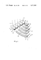
- FIG. 1 shows a perspective view of a rotary drill bit which is equipped with obliquely set and straight set cutting elements
- FIG. 2 shows in detail a portion of the bit head with obliquely set cutting faces orientated towards the marginal region
- FIG. 3 shows in detail another portion of the bit head with obliquely set cutting faces orientated towards the central region
- FIG. 4 shows a plan view, transferred into the plane, of a group of cutting elements with straight set cutting faces and a further group of cutting elements with obliquely set cutting faces set towards the marginal region;
- FIG. 5 shows a plan view, transferred into the plane, of a group of cutting elements with straight set cutting faces and a further group of cutting elements with cutting faces obliquely set towards the central region;
- FIG. 6 shows a combination of the configurations illustrated in FIGS. 4 and 5;
- FIG. 7 shows a plan view, transferred into the plane, of a group of cutting elements with straight set cutting faces and a group of cutting elements with obliquely set cutting faces, two cutting elements with obliquely set cutting faces being allocated to the cutting width of each of the cutting elements with straight set faces;
- FIG. 8 shows a plan view, transferred into the plane, of a group of cutting elements with straight set cutting faces, a group of cutting elements with obliquely set cutting faces at an angle of about 45 degrees and a further group of cutting elements with cutting faces set very obliquely at an angle of about 20 degrees;
- FIGS. 9-15 show further arrangements of cutting elements.
- a rotary drill bit which comprises a connection member 1, a threaded pin 2 for a connection to a drilling string and a head with cutting edges 3, 4.
- the cutting edges 3 and 4 contain cutting elements 5 and 6 combined projecting in strip-shaped groups and extend in a wall-like raised portion radially from the marginal region of the bit to the center. In the marginal region, this raised portion is continued over a short axial distance and equipped with a hard covering 7 which is impregnated or provided on the surface with abrasion-resistant pieces.
- nozzles 8, 9 Disposed in the valleys between the raised portions, in front of the cutting elements in each case are nozzles 8, 9 which are intended to direct the flushing stream and are in communication with an internal bore at the inlet side.
- the outlet cones of the nozzles are so dimensioned that all the cutting elements are adequately supplied with flushing.
- the nozzles 8 are so aligned that they impress a direction tangential to the drill bit towards the cutting elements 5 on the flushing stream.
- the nozzles 9 on the other hand impress a radial component towards the marginal region of the bit on the flushing stream as a result of their alignment.
- the cutting elements 5 and 6 consist of small thin plates of polycrystalline sintered diamond which are circular in plan view and are secured to hard metal supporting members. These in turn are embedded in a matrix binding-agent composition.
- the cutting faces of the cutting elements 5 are substantially at right angles to the cutting direction, while the cutting faces of the cutting elements 6 are at an angle of about 45 degrees to the cutting direction. The component of the cutting faces associated with these angles extends tangentially to the local surface segment.
- FIGS. 2 and 3 show, as detail sketches, the two alternatives in the alignment of the cutting faces of obliquely set cutting elements.
- the cutting faces face towards the marginal region of the head while in FIG. 3 they are orientated towards the central region.
- FIG. 4 shows a plan view, transferred into the plane, of a cooperating pair of cutting edges. This consists of the cutting edge 3 carrying the cutting elements with obliquely set cutting faces 12 and the cutting edge 4 carrying cutting elements 6 with straight set cutting faces 13.
- the reference numerals 18 and 19 distinguish the cutting plates set obliquely at the angle ⁇ and the bevelled supporting members, while the reference numerals 16 and 17 designate the cutting plates disposed at the angle ⁇ to the cutting direction and so set straight and their supporting members.
- the cutting faces of the obliquely set cutting elements are designated by 12, while the cutting faces of the straight set cutting elements are designated by 13.
- the cutting lines 10 and 11, which distinguish the position of the deepest penetration of the cutting elements in the formation, show that the cutting elements are staggered.
- the flushing flow impressed by the nozzles, not shown, is illustrated by arrows 14 and 15.
- the flushing stream runs at first in the opposite direction to the direction of rotation of the bit through the gaps in the obliquely set cutting elements 5 and changes its direction to the outside along the straight set cutting elements 6.
- the drillings pared off are indicated in the drawing along the path described from the cutting elements. Whereas the formation is only broken up by the obliquely set cutting elements, the further paring off is effected by the straight set cutting elements.
- FIG. 5 differs from that of FIG. 4 by the different orientation of the cutting plates 18 of the obliquely set cutting elements 5.
- the cutting faces face towards the central region of the head.
- the angle between the cutting faces 12 and the cutting direction is designated by ⁇ ', but as regards amount has the same value as ⁇ .
- FIG. 6 A combination of the two embodiments in FIGS. 4, 5 is illustrated in FIG. 6.
- the orientation of their cutting faces alternates from one cutting edge to the next.
- the penetration behaviour of a bit thus equipped in the formation is neutral.
- the illustration of the obliquely set cutting elements is restricted to the version with the cutting faces facing towards the marginal region of the head; it is also possible, however, in the following examples, to realize the other alternative or a combination of both.
- FIG. 7 shows obliquely set cutting elements 20 which are set on a cutting edge 24 at a very acute angle to the cutting direction.
- the reference numerals 21 are used for the cutting plates, 22 for the supporting members and 23 for the cutting faces.
- This embodiment is particularly advantageous when a shaft has to be sunk through very plastic material and an adequate pressure per unit area cannot be exerted on the formation by cutting elements set less obliquely--for example 5 from FIG. 4. Because of the smaller cutting width of the individual cutting elements, here a larger number is aligned side by side so that the following cutting elements 6 again find a sufficiently wide prepared surface in front of them for the removal with a cutting action. If it is difficult to arrange the obliquely set cutting elements side by side for reasons of space, they may also be staggered in arc measure.
- FIGS. 9, 10, 11 show a combined arrangement of the different cutting elements 5, 6 on each cutting edge 25, 26, 27.
- the formation is torn up by the cutting elements 5 with obliquely set cutting faces and pared off by the cutting elements with a straight cutting face disposed on the cutting edge situated behind in the direction of rotation.
- the tearing up and paring off of the formation is effected by the same cutting edge 26 because this already comprises the two kinds of cutting elements in the arrangement corresponding to the working sequence, namely cutting elements 6 behind cutting elements 5.
- FIGS. 12, 13, 14 show arrangements which consist of a combination of the cutting edges 25, 26, 27, as illustrated in FIGS. 9, 10, 11, with the cutting edges 3 and 4 from FIG. 4.
- the cooperation of the straight set and obliquely set cutting elements 5, 6 is also possible when the cutting elements are disposed partially together, partially separately on the cutting edges.
- the cutting elements 5, 6 are disposed distributed over the surface of the bit.
- the cutting elements are constructed in the form of modules 28 and are each provided with outlets 29 for the flushing liquid associated with the cutting faces.
- the term "horizontal" refers to any plane perpendicular to the axis of rotation of the drill bit.
Abstract
Description
Claims (13)
Applications Claiming Priority (2)
| Application Number | Priority Date | Filing Date | Title |
|---|---|---|---|
| DE3113109A DE3113109C2 (en) | 1981-04-01 | 1981-04-01 | Rotary drill bit for deep drilling |
| DE3113109 | 1981-04-01 |
Publications (1)
| Publication Number | Publication Date |
|---|---|
| US4471845A true US4471845A (en) | 1984-09-18 |
Family
ID=6129037
Family Applications (1)
| Application Number | Title | Priority Date | Filing Date |
|---|---|---|---|
| US06/361,669 Expired - Lifetime US4471845A (en) | 1981-04-01 | 1982-03-25 | Rotary drill bit |
Country Status (7)
| Country | Link |
|---|---|
| US (1) | US4471845A (en) |
| BE (1) | BE892488A (en) |
| CA (1) | CA1165755A (en) |
| DE (1) | DE3113109C2 (en) |
| FR (1) | FR2503242B1 (en) |
| GB (1) | GB2095724B (en) |
| NL (1) | NL8201012A (en) |
Cited By (59)
| Publication number | Priority date | Publication date | Assignee | Title |
|---|---|---|---|---|
| WO1986005542A1 (en) * | 1985-03-20 | 1986-09-25 | Siegfried Treitz | Percussion drill bit for stone drilling machines |
| US4679639A (en) * | 1983-12-03 | 1987-07-14 | Nl Petroleum Products Limited | Rotary drill bits and cutting elements for such bits |
| US4705122A (en) * | 1985-01-15 | 1987-11-10 | Nl Petroleum Products Limited | Cutter assemblies for rotary drill bits |
| FR2606069A1 (en) * | 1986-11-04 | 1988-05-06 | Vennin Henri | Rotary monobloc drilling tool |
| EP0269400A2 (en) * | 1986-11-22 | 1988-06-01 | Reed Tool Company Limited | Improvements in or relating to rotary drill bits |
| US4794994A (en) * | 1987-03-26 | 1989-01-03 | Reed Tool Company | Drag drill bit having improved flow of drilling fluid |
| US4858706A (en) * | 1987-09-15 | 1989-08-22 | Lebourgh Maurice P | Diamond drill bit with hemispherically shaped diamond inserts |
| US4913244A (en) * | 1986-09-11 | 1990-04-03 | Eastman Christensen Company | Large compact cutter rotary drill bit utilizing directed hydraulics for each cutter |
| US4932484A (en) * | 1989-04-10 | 1990-06-12 | Amoco Corporation | Whirl resistant bit |
| US4989578A (en) * | 1989-08-30 | 1991-02-05 | Lebourg Maurice P | Method for forming diamond cutting elements for a diamond drill bit |
| US5115873A (en) * | 1991-01-24 | 1992-05-26 | Baker Hughes Incorporated | Method and appartus for directing drilling fluid to the cutting edge of a cutter |
| US5247923A (en) * | 1992-03-09 | 1993-09-28 | Lebourg Maurice P | Method of forming a diamond drill bit element using laser trimming |
| USRE34435E (en) * | 1989-04-10 | 1993-11-09 | Amoco Corporation | Whirl resistant bit |
| US5265685A (en) * | 1991-12-30 | 1993-11-30 | Dresser Industries, Inc. | Drill bit with improved insert cutter pattern |
| US5531281A (en) * | 1993-07-16 | 1996-07-02 | Camco Drilling Group Ltd. | Rotary drilling tools |
| US5549171A (en) * | 1994-08-10 | 1996-08-27 | Smith International, Inc. | Drill bit with performance-improving cutting structure |
| US5551522A (en) * | 1994-10-12 | 1996-09-03 | Smith International, Inc. | Drill bit having stability enhancing cutting structure |
| US5582261A (en) * | 1994-08-10 | 1996-12-10 | Smith International, Inc. | Drill bit having enhanced cutting structure and stabilizing features |
| US5592996A (en) * | 1994-10-03 | 1997-01-14 | Smith International, Inc. | Drill bit having improved cutting structure with varying diamond density |
| US5607025A (en) * | 1995-06-05 | 1997-03-04 | Smith International, Inc. | Drill bit and cutting structure having enhanced placement and sizing of cutters for improved bit stabilization |
| US5651421A (en) * | 1994-11-01 | 1997-07-29 | Camco Drilling Group Limited | Rotary drill bits |
| US5957227A (en) * | 1996-11-20 | 1999-09-28 | Total | Blade-equipped drilling tool, incorporating secondary cutting edges and passages designed for the removal of evacuated material |
| US5967245A (en) * | 1996-06-21 | 1999-10-19 | Smith International, Inc. | Rolling cone bit having gage and nestled gage cutter elements having enhancements in materials and geometry to optimize borehole corner cutting duty |
| US6119797A (en) * | 1998-03-19 | 2000-09-19 | Kingdream Public Ltd. Co. | Single cone earth boring bit |
| US6123161A (en) * | 1997-06-14 | 2000-09-26 | Camco International (Uk) Limited | Rotary drill bits |
| US6283233B1 (en) * | 1996-12-16 | 2001-09-04 | Dresser Industries, Inc | Drilling and/or coring tool |
| US6481511B2 (en) * | 2000-09-20 | 2002-11-19 | Camco International (U.K.) Limited | Rotary drill bit |
| US7228922B1 (en) | 2004-06-08 | 2007-06-12 | Devall Donald L | Drill bit |
| US20070144789A1 (en) * | 2005-10-25 | 2007-06-28 | Simon Johnson | Representation of whirl in fixed cutter drill bits |
| US20070261890A1 (en) * | 2006-05-10 | 2007-11-15 | Smith International, Inc. | Fixed Cutter Bit With Centrally Positioned Backup Cutter Elements |
| US20080105466A1 (en) * | 2006-10-02 | 2008-05-08 | Hoffmaster Carl M | Drag Bits with Dropping Tendencies and Methods for Making the Same |
| US20080135297A1 (en) * | 2006-12-07 | 2008-06-12 | David Gavia | Rotary drag bits having a pilot cutter configuraton and method to pre-fracture subterranean formations therewith |
| US20080179107A1 (en) * | 2007-01-25 | 2008-07-31 | Doster Michael L | Rotary drag bit and methods therefor |
| US20080302575A1 (en) * | 2007-06-11 | 2008-12-11 | Smith International, Inc. | Fixed Cutter Bit With Backup Cutter Elements on Primary Blades |
| US7513319B2 (en) | 2004-06-08 | 2009-04-07 | Devall Donald L | Reamer bit |
| US20090145669A1 (en) * | 2007-12-07 | 2009-06-11 | Smith International, Inc. | Drill Bit Cutting Structure and Methods to Maximize Depth-0f-Cut For Weight on Bit Applied |
| US20090266619A1 (en) * | 2008-04-01 | 2009-10-29 | Smith International, Inc. | Fixed Cutter Bit With Backup Cutter Elements on Secondary Blades |
| US20110024200A1 (en) * | 2009-07-08 | 2011-02-03 | Baker Hughes Incorporated | Cutting element and method of forming thereof |
| US20110155472A1 (en) * | 2009-12-28 | 2011-06-30 | Baker Hughes Incorporated | Earth-boring tools having differing cutting elements on a blade and related methods |
| US20110192651A1 (en) * | 2010-02-05 | 2011-08-11 | Baker Hughes Incorporated | Shaped cutting elements on drill bits and other earth-boring tools, and methods of forming same |
| US20110278073A1 (en) * | 2009-01-30 | 2011-11-17 | Sean Gillis | Drill bit |
| US20120080240A1 (en) * | 2010-10-05 | 2012-04-05 | Baker Hughes Incorporated | Diamond impregnated cutting structures, earth-boring drill bits and other tools including diamond impregnated cutting structures, and related methods |
| US8408338B2 (en) * | 2009-09-15 | 2013-04-02 | Baker Hughes Incorporated | Impregnated rotary drag bit with enhanced drill out capability |
| US8500833B2 (en) | 2009-07-27 | 2013-08-06 | Baker Hughes Incorporated | Abrasive article and method of forming |
| US8851207B2 (en) | 2011-05-05 | 2014-10-07 | Baker Hughes Incorporated | Earth-boring tools and methods of forming such earth-boring tools |
| US8887839B2 (en) | 2009-06-25 | 2014-11-18 | Baker Hughes Incorporated | Drill bit for use in drilling subterranean formations |
| US8978788B2 (en) | 2009-07-08 | 2015-03-17 | Baker Hughes Incorporated | Cutting element for a drill bit used in drilling subterranean formations |
| US9022149B2 (en) | 2010-08-06 | 2015-05-05 | Baker Hughes Incorporated | Shaped cutting elements for earth-boring tools, earth-boring tools including such cutting elements, and related methods |
| CN104847274A (en) * | 2015-05-19 | 2015-08-19 | 中国水利水电第十工程局有限公司 | Multi-head arc cutting type semispherical drill bit |
| US9212523B2 (en) | 2011-12-01 | 2015-12-15 | Smith International, Inc. | Drill bit having geometrically sharp inserts |
| US9267333B2 (en) | 2009-03-02 | 2016-02-23 | Baker Hughes Incorporated | Impregnated bit with improved cutting structure and blade geometry |
| US9316058B2 (en) | 2012-02-08 | 2016-04-19 | Baker Hughes Incorporated | Drill bits and earth-boring tools including shaped cutting elements |
| US9556683B2 (en) | 2012-12-03 | 2017-01-31 | Ulterra Drilling Technologies, L.P. | Earth boring tool with improved arrangement of cutter side rakes |
| US9662757B2 (en) | 2013-02-01 | 2017-05-30 | Global Polishing Systems, Llc | Concrete cutting, polishing and coloring treatment solutions and methods |
| US10344537B2 (en) * | 2016-07-28 | 2019-07-09 | Baker Hughes Incorporated | Earth-boring tools, methods of forming earth-boring tools, and methods of forming a borehole in a subterranean formation |
| US10851594B2 (en) | 2011-02-10 | 2020-12-01 | Smith International, Inc. | Kerfing hybrid drill bit and other downhole cutting tools |
| US20220120140A1 (en) * | 2020-10-19 | 2022-04-21 | Taurex Drill Bits, LLC | Drill bits with variable cutter alignment |
| US11471998B2 (en) | 2013-02-01 | 2022-10-18 | Global Polishing Systems, Llc | Tools for polishing and refinishing concrete and methods for using the same |
| US11480016B2 (en) | 2018-11-12 | 2022-10-25 | Ulterra Drilling Technologies, L.P. | Drill bit |
Families Citing this family (11)
| Publication number | Priority date | Publication date | Assignee | Title |
|---|---|---|---|---|
| US4558753A (en) * | 1983-02-22 | 1985-12-17 | Nl Industries, Inc. | Drag bit and cutters |
| US4538690A (en) * | 1983-02-22 | 1985-09-03 | Nl Industries, Inc. | PDC cutter and bit |
| US4550790A (en) * | 1983-02-28 | 1985-11-05 | Norton Christensen, Inc. | Diamond rotating bit |
| US4499959A (en) * | 1983-03-14 | 1985-02-19 | Christensen, Inc. | Tooth configuration for an earth boring bit |
| US4512426A (en) * | 1983-04-11 | 1985-04-23 | Christensen, Inc. | Rotating bits including a plurality of types of preferential cutting elements |
| US4862977A (en) * | 1984-01-31 | 1989-09-05 | Reed Tool Company, Ltd. | Drill bit and cutter therefor |
| GB8418481D0 (en) * | 1984-07-19 | 1984-08-22 | Nl Petroleum Prod | Rotary drill bits |
| US4991670A (en) * | 1984-07-19 | 1991-02-12 | Reed Tool Company, Ltd. | Rotary drill bit for use in drilling holes in subsurface earth formations |
| US4981184A (en) * | 1988-11-21 | 1991-01-01 | Smith International, Inc. | Diamond drag bit for soft formations |
| US5314033A (en) * | 1992-02-18 | 1994-05-24 | Baker Hughes Incorporated | Drill bit having combined positive and negative or neutral rake cutters |
| US7730976B2 (en) | 2007-10-31 | 2010-06-08 | Baker Hughes Incorporated | Impregnated rotary drag bit and related methods |
Citations (9)
| Publication number | Priority date | Publication date | Assignee | Title |
|---|---|---|---|---|
| US883137A (en) * | 1907-02-23 | 1908-03-24 | J P Karns Tunneling Machine Co | Drill-head and cutter-blade therefor. |
| US977955A (en) * | 1909-05-25 | 1910-12-06 | J P Karns Tunneling Machine Co | Cutter-head for tunneling-machines. |
| US2960312A (en) * | 1957-06-07 | 1960-11-15 | Charles W Kandle | Drill cutting head |
| US3709308A (en) * | 1970-12-02 | 1973-01-09 | Christensen Diamond Prod Co | Diamond drill bits |
| DE2817986A1 (en) * | 1977-04-25 | 1978-11-02 | Christensen Inc | DEEP DRILLING CHISEL |
| DE2835660A1 (en) * | 1977-08-17 | 1979-03-01 | Shell Int Research | DRILL BIT FOR DEEP DRILLING |
| US4246977A (en) * | 1979-04-09 | 1981-01-27 | Smith International, Inc. | Diamond studded insert drag bit with strategically located hydraulic passages for mud motors |
| US4350215A (en) * | 1978-09-18 | 1982-09-21 | Nl Industries Inc. | Drill bit and method of manufacture |
| US4351401A (en) * | 1978-06-08 | 1982-09-28 | Christensen, Inc. | Earth-boring drill bits |
Family Cites Families (7)
| Publication number | Priority date | Publication date | Assignee | Title |
|---|---|---|---|---|
| CA659574A (en) * | 1963-03-19 | H. Davis Sidney | Drilling bit | |
| DE270185C (en) * | ||||
| US2648524A (en) * | 1946-11-23 | 1953-08-11 | Dionisotti Joseph | Mining trepan |
| DE1054039B (en) * | 1958-02-03 | 1959-04-02 | Salzgitter Maschinen Ag | Drill bits |
| DD40351A (en) * | 1963-06-14 | 1965-08-05 | ||
| DE2620869A1 (en) * | 1976-05-11 | 1977-12-01 | Krupp Gmbh | Rotary percussive drill tool - has radial blade and second blade vertical to outside tool endface centre point |
| DE3039632C2 (en) * | 1980-10-21 | 1982-12-16 | Christensen, Inc., 84115 Salt Lake City, Utah | Rotary bit for deep drilling |
-
1981
- 1981-04-01 DE DE3113109A patent/DE3113109C2/en not_active Expired
-
1982
- 1982-02-23 GB GB8205320A patent/GB2095724B/en not_active Expired
- 1982-03-11 NL NL8201012A patent/NL8201012A/en not_active Application Discontinuation
- 1982-03-12 BE BE0/207568A patent/BE892488A/en not_active IP Right Cessation
- 1982-03-17 FR FR8204552A patent/FR2503242B1/en not_active Expired
- 1982-03-18 CA CA000398727A patent/CA1165755A/en not_active Expired
- 1982-03-25 US US06/361,669 patent/US4471845A/en not_active Expired - Lifetime
Patent Citations (9)
| Publication number | Priority date | Publication date | Assignee | Title |
|---|---|---|---|---|
| US883137A (en) * | 1907-02-23 | 1908-03-24 | J P Karns Tunneling Machine Co | Drill-head and cutter-blade therefor. |
| US977955A (en) * | 1909-05-25 | 1910-12-06 | J P Karns Tunneling Machine Co | Cutter-head for tunneling-machines. |
| US2960312A (en) * | 1957-06-07 | 1960-11-15 | Charles W Kandle | Drill cutting head |
| US3709308A (en) * | 1970-12-02 | 1973-01-09 | Christensen Diamond Prod Co | Diamond drill bits |
| DE2817986A1 (en) * | 1977-04-25 | 1978-11-02 | Christensen Inc | DEEP DRILLING CHISEL |
| DE2835660A1 (en) * | 1977-08-17 | 1979-03-01 | Shell Int Research | DRILL BIT FOR DEEP DRILLING |
| US4351401A (en) * | 1978-06-08 | 1982-09-28 | Christensen, Inc. | Earth-boring drill bits |
| US4350215A (en) * | 1978-09-18 | 1982-09-21 | Nl Industries Inc. | Drill bit and method of manufacture |
| US4246977A (en) * | 1979-04-09 | 1981-01-27 | Smith International, Inc. | Diamond studded insert drag bit with strategically located hydraulic passages for mud motors |
Cited By (91)
| Publication number | Priority date | Publication date | Assignee | Title |
|---|---|---|---|---|
| US4679639A (en) * | 1983-12-03 | 1987-07-14 | Nl Petroleum Products Limited | Rotary drill bits and cutting elements for such bits |
| US4705122A (en) * | 1985-01-15 | 1987-11-10 | Nl Petroleum Products Limited | Cutter assemblies for rotary drill bits |
| EP0199040A1 (en) * | 1985-03-20 | 1986-10-29 | Siegfried Treitz | Percussion bit for rock drills |
| US4771834A (en) * | 1985-03-20 | 1988-09-20 | Siegfried Treitz | Percussion drill bit for rock perforators |
| AU584181B2 (en) * | 1985-03-20 | 1989-05-18 | Siegfried Treitz | Percussion bit for rock drill |
| WO1986005542A1 (en) * | 1985-03-20 | 1986-09-25 | Siegfried Treitz | Percussion drill bit for stone drilling machines |
| US4913244A (en) * | 1986-09-11 | 1990-04-03 | Eastman Christensen Company | Large compact cutter rotary drill bit utilizing directed hydraulics for each cutter |
| FR2606069A1 (en) * | 1986-11-04 | 1988-05-06 | Vennin Henri | Rotary monobloc drilling tool |
| EP0269400A2 (en) * | 1986-11-22 | 1988-06-01 | Reed Tool Company Limited | Improvements in or relating to rotary drill bits |
| EP0269400A3 (en) * | 1986-11-22 | 1989-08-16 | Reed Tool Company Limited | Improvements in or relating to rotary drill bits |
| US4794994A (en) * | 1987-03-26 | 1989-01-03 | Reed Tool Company | Drag drill bit having improved flow of drilling fluid |
| US4858706A (en) * | 1987-09-15 | 1989-08-22 | Lebourgh Maurice P | Diamond drill bit with hemispherically shaped diamond inserts |
| US4932484A (en) * | 1989-04-10 | 1990-06-12 | Amoco Corporation | Whirl resistant bit |
| WO1990012192A1 (en) * | 1989-04-10 | 1990-10-18 | Amoco Corporation | Whirl resistant bit |
| USRE34435E (en) * | 1989-04-10 | 1993-11-09 | Amoco Corporation | Whirl resistant bit |
| US4989578A (en) * | 1989-08-30 | 1991-02-05 | Lebourg Maurice P | Method for forming diamond cutting elements for a diamond drill bit |
| US5115873A (en) * | 1991-01-24 | 1992-05-26 | Baker Hughes Incorporated | Method and appartus for directing drilling fluid to the cutting edge of a cutter |
| US5265685A (en) * | 1991-12-30 | 1993-11-30 | Dresser Industries, Inc. | Drill bit with improved insert cutter pattern |
| US5346025A (en) * | 1991-12-30 | 1994-09-13 | Dresser Industries, Inc. | Drill bit with improved insert cutter pattern and method of drilling |
| US5247923A (en) * | 1992-03-09 | 1993-09-28 | Lebourg Maurice P | Method of forming a diamond drill bit element using laser trimming |
| US5531281A (en) * | 1993-07-16 | 1996-07-02 | Camco Drilling Group Ltd. | Rotary drilling tools |
| US5549171A (en) * | 1994-08-10 | 1996-08-27 | Smith International, Inc. | Drill bit with performance-improving cutting structure |
| US5582261A (en) * | 1994-08-10 | 1996-12-10 | Smith International, Inc. | Drill bit having enhanced cutting structure and stabilizing features |
| US5592996A (en) * | 1994-10-03 | 1997-01-14 | Smith International, Inc. | Drill bit having improved cutting structure with varying diamond density |
| US5551522A (en) * | 1994-10-12 | 1996-09-03 | Smith International, Inc. | Drill bit having stability enhancing cutting structure |
| US5651421A (en) * | 1994-11-01 | 1997-07-29 | Camco Drilling Group Limited | Rotary drill bits |
| US5607025A (en) * | 1995-06-05 | 1997-03-04 | Smith International, Inc. | Drill bit and cutting structure having enhanced placement and sizing of cutters for improved bit stabilization |
| US5967245A (en) * | 1996-06-21 | 1999-10-19 | Smith International, Inc. | Rolling cone bit having gage and nestled gage cutter elements having enhancements in materials and geometry to optimize borehole corner cutting duty |
| US5957227A (en) * | 1996-11-20 | 1999-09-28 | Total | Blade-equipped drilling tool, incorporating secondary cutting edges and passages designed for the removal of evacuated material |
| US6283233B1 (en) * | 1996-12-16 | 2001-09-04 | Dresser Industries, Inc | Drilling and/or coring tool |
| US6123161A (en) * | 1997-06-14 | 2000-09-26 | Camco International (Uk) Limited | Rotary drill bits |
| US6119797A (en) * | 1998-03-19 | 2000-09-19 | Kingdream Public Ltd. Co. | Single cone earth boring bit |
| US6481511B2 (en) * | 2000-09-20 | 2002-11-19 | Camco International (U.K.) Limited | Rotary drill bit |
| US7228922B1 (en) | 2004-06-08 | 2007-06-12 | Devall Donald L | Drill bit |
| US7513319B2 (en) | 2004-06-08 | 2009-04-07 | Devall Donald L | Reamer bit |
| US7457734B2 (en) | 2005-10-25 | 2008-11-25 | Reedhycalog Uk Limited | Representation of whirl in fixed cutter drill bits |
| US20070144789A1 (en) * | 2005-10-25 | 2007-06-28 | Simon Johnson | Representation of whirl in fixed cutter drill bits |
| US20070261890A1 (en) * | 2006-05-10 | 2007-11-15 | Smith International, Inc. | Fixed Cutter Bit With Centrally Positioned Backup Cutter Elements |
| US20080105466A1 (en) * | 2006-10-02 | 2008-05-08 | Hoffmaster Carl M | Drag Bits with Dropping Tendencies and Methods for Making the Same |
| US7621348B2 (en) | 2006-10-02 | 2009-11-24 | Smith International, Inc. | Drag bits with dropping tendencies and methods for making the same |
| US20080135297A1 (en) * | 2006-12-07 | 2008-06-12 | David Gavia | Rotary drag bits having a pilot cutter configuraton and method to pre-fracture subterranean formations therewith |
| US7896106B2 (en) | 2006-12-07 | 2011-03-01 | Baker Hughes Incorporated | Rotary drag bits having a pilot cutter configuraton and method to pre-fracture subterranean formations therewith |
| US20080179106A1 (en) * | 2007-01-25 | 2008-07-31 | Baker Hughes Incorporated | Rotary drag bit |
| US20080179108A1 (en) * | 2007-01-25 | 2008-07-31 | Mcclain Eric E | Rotary drag bit and methods therefor |
| US20080179107A1 (en) * | 2007-01-25 | 2008-07-31 | Doster Michael L | Rotary drag bit and methods therefor |
| US7861809B2 (en) | 2007-01-25 | 2011-01-04 | Baker Hughes Incorporated | Rotary drag bit with multiple backup cutters |
| US7762355B2 (en) | 2007-01-25 | 2010-07-27 | Baker Hughes Incorporated | Rotary drag bit and methods therefor |
| US20080302575A1 (en) * | 2007-06-11 | 2008-12-11 | Smith International, Inc. | Fixed Cutter Bit With Backup Cutter Elements on Primary Blades |
| US7703557B2 (en) | 2007-06-11 | 2010-04-27 | Smith International, Inc. | Fixed cutter bit with backup cutter elements on primary blades |
| US20090145669A1 (en) * | 2007-12-07 | 2009-06-11 | Smith International, Inc. | Drill Bit Cutting Structure and Methods to Maximize Depth-0f-Cut For Weight on Bit Applied |
| US9016407B2 (en) | 2007-12-07 | 2015-04-28 | Smith International, Inc. | Drill bit cutting structure and methods to maximize depth-of-cut for weight on bit applied |
| US20090266619A1 (en) * | 2008-04-01 | 2009-10-29 | Smith International, Inc. | Fixed Cutter Bit With Backup Cutter Elements on Secondary Blades |
| US8100202B2 (en) | 2008-04-01 | 2012-01-24 | Smith International, Inc. | Fixed cutter bit with backup cutter elements on secondary blades |
| US20110278073A1 (en) * | 2009-01-30 | 2011-11-17 | Sean Gillis | Drill bit |
| US8991526B2 (en) * | 2009-01-30 | 2015-03-31 | Drilformance Technologies, Llc | Drill bit |
| US9267333B2 (en) | 2009-03-02 | 2016-02-23 | Baker Hughes Incorporated | Impregnated bit with improved cutting structure and blade geometry |
| US8887839B2 (en) | 2009-06-25 | 2014-11-18 | Baker Hughes Incorporated | Drill bit for use in drilling subterranean formations |
| US9957757B2 (en) | 2009-07-08 | 2018-05-01 | Baker Hughes Incorporated | Cutting elements for drill bits for drilling subterranean formations and methods of forming such cutting elements |
| US20110024200A1 (en) * | 2009-07-08 | 2011-02-03 | Baker Hughes Incorporated | Cutting element and method of forming thereof |
| US9816324B2 (en) | 2009-07-08 | 2017-11-14 | Baker Hughes | Cutting element incorporating a cutting body and sleeve and method of forming thereof |
| US8757299B2 (en) | 2009-07-08 | 2014-06-24 | Baker Hughes Incorporated | Cutting element and method of forming thereof |
| US8978788B2 (en) | 2009-07-08 | 2015-03-17 | Baker Hughes Incorporated | Cutting element for a drill bit used in drilling subterranean formations |
| US10309157B2 (en) | 2009-07-08 | 2019-06-04 | Baker Hughes Incorporated | Cutting element incorporating a cutting body and sleeve and an earth-boring tool including the cutting element |
| US10012030B2 (en) | 2009-07-27 | 2018-07-03 | Baker Hughes, A Ge Company, Llc | Abrasive articles and earth-boring tools |
| US8500833B2 (en) | 2009-07-27 | 2013-08-06 | Baker Hughes Incorporated | Abrasive article and method of forming |
| US9174325B2 (en) | 2009-07-27 | 2015-11-03 | Baker Hughes Incorporated | Methods of forming abrasive articles |
| US9744646B2 (en) | 2009-07-27 | 2017-08-29 | Baker Hughes Incorporated | Methods of forming abrasive articles |
| US8408338B2 (en) * | 2009-09-15 | 2013-04-02 | Baker Hughes Incorporated | Impregnated rotary drag bit with enhanced drill out capability |
| US8505634B2 (en) | 2009-12-28 | 2013-08-13 | Baker Hughes Incorporated | Earth-boring tools having differing cutting elements on a blade and related methods |
| US20110155472A1 (en) * | 2009-12-28 | 2011-06-30 | Baker Hughes Incorporated | Earth-boring tools having differing cutting elements on a blade and related methods |
| US8794356B2 (en) | 2010-02-05 | 2014-08-05 | Baker Hughes Incorporated | Shaped cutting elements on drill bits and other earth-boring tools, and methods of forming same |
| US20110192651A1 (en) * | 2010-02-05 | 2011-08-11 | Baker Hughes Incorporated | Shaped cutting elements on drill bits and other earth-boring tools, and methods of forming same |
| US9200483B2 (en) | 2010-06-03 | 2015-12-01 | Baker Hughes Incorporated | Earth-boring tools and methods of forming such earth-boring tools |
| US9458674B2 (en) | 2010-08-06 | 2016-10-04 | Baker Hughes Incorporated | Earth-boring tools including shaped cutting elements, and related methods |
| US9022149B2 (en) | 2010-08-06 | 2015-05-05 | Baker Hughes Incorporated | Shaped cutting elements for earth-boring tools, earth-boring tools including such cutting elements, and related methods |
| US9567807B2 (en) * | 2010-10-05 | 2017-02-14 | Baker Hughes Incorporated | Diamond impregnated cutting structures, earth-boring drill bits and other tools including diamond impregnated cutting structures, and related methods |
| US20120080240A1 (en) * | 2010-10-05 | 2012-04-05 | Baker Hughes Incorporated | Diamond impregnated cutting structures, earth-boring drill bits and other tools including diamond impregnated cutting structures, and related methods |
| US10851594B2 (en) | 2011-02-10 | 2020-12-01 | Smith International, Inc. | Kerfing hybrid drill bit and other downhole cutting tools |
| US8851207B2 (en) | 2011-05-05 | 2014-10-07 | Baker Hughes Incorporated | Earth-boring tools and methods of forming such earth-boring tools |
| US9212523B2 (en) | 2011-12-01 | 2015-12-15 | Smith International, Inc. | Drill bit having geometrically sharp inserts |
| US10017998B2 (en) | 2012-02-08 | 2018-07-10 | Baker Hughes Incorporated | Drill bits and earth-boring tools including shaped cutting elements and associated methods |
| US9316058B2 (en) | 2012-02-08 | 2016-04-19 | Baker Hughes Incorporated | Drill bits and earth-boring tools including shaped cutting elements |
| US10563463B2 (en) | 2012-12-03 | 2020-02-18 | Ulterra Drilling Technologies, L.P. | Earth boring tool with improved arrangements of cutter side rakes |
| US9556683B2 (en) | 2012-12-03 | 2017-01-31 | Ulterra Drilling Technologies, L.P. | Earth boring tool with improved arrangement of cutter side rakes |
| US9662757B2 (en) | 2013-02-01 | 2017-05-30 | Global Polishing Systems, Llc | Concrete cutting, polishing and coloring treatment solutions and methods |
| US10343254B2 (en) | 2013-02-01 | 2019-07-09 | Global Polishing Systems, Llc | Concrete cutting, polishing, and coloring treatment solutions and methods |
| US11471998B2 (en) | 2013-02-01 | 2022-10-18 | Global Polishing Systems, Llc | Tools for polishing and refinishing concrete and methods for using the same |
| CN104847274A (en) * | 2015-05-19 | 2015-08-19 | 中国水利水电第十工程局有限公司 | Multi-head arc cutting type semispherical drill bit |
| US10344537B2 (en) * | 2016-07-28 | 2019-07-09 | Baker Hughes Incorporated | Earth-boring tools, methods of forming earth-boring tools, and methods of forming a borehole in a subterranean formation |
| US11480016B2 (en) | 2018-11-12 | 2022-10-25 | Ulterra Drilling Technologies, L.P. | Drill bit |
| US20220120140A1 (en) * | 2020-10-19 | 2022-04-21 | Taurex Drill Bits, LLC | Drill bits with variable cutter alignment |
Also Published As
| Publication number | Publication date |
|---|---|
| GB2095724B (en) | 1985-01-23 |
| FR2503242B1 (en) | 1987-08-21 |
| NL8201012A (en) | 1982-11-01 |
| DE3113109A1 (en) | 1982-11-04 |
| BE892488A (en) | 1982-07-01 |
| DE3113109C2 (en) | 1983-11-17 |
| CA1165755A (en) | 1984-04-17 |
| FR2503242A1 (en) | 1982-10-08 |
| GB2095724A (en) | 1982-10-06 |
Similar Documents
| Publication | Publication Date | Title |
|---|---|---|
| US4471845A (en) | Rotary drill bit | |
| CA1159047A (en) | Rotary drill bit for deep-well drilling | |
| US4246977A (en) | Diamond studded insert drag bit with strategically located hydraulic passages for mud motors | |
| US4606418A (en) | Cutting means for drag drill bits | |
| US4253533A (en) | Variable wear pad for crossflow drag bit | |
| US3135341A (en) | Diamond drill bits | |
| US6450270B1 (en) | Rotary cone bit for cutting removal | |
| US3938599A (en) | Rotary drill bit | |
| EP0370717B1 (en) | Diamond drag bit for soft formations | |
| US5291807A (en) | Patterned hardfacing shapes on insert cutter cones | |
| US4538691A (en) | Rotary drill bit | |
| CA1155833A (en) | Hybrid rock bit | |
| EP0239328B1 (en) | Drill bits | |
| EP0418706B1 (en) | Earth boring bit for soft to hard formations | |
| US6688410B1 (en) | Hydro-lifter rock bit with PDC inserts | |
| US4203496A (en) | Longitudinal axis roller drill bit with gage inserts protection | |
| US5103922A (en) | Fishtail expendable diamond drag bit | |
| PL122483B1 (en) | Roller rock bit | |
| AU612454B2 (en) | Method and apparatus for establishing hydraulic flow regime in drill bits | |
| EP0496417A1 (en) | Method and apparatus for directing drilling fluid to the cutting edge of a cutter | |
| US4848491A (en) | Rotary drill bits | |
| US4776411A (en) | Fluid flow control for drag bits | |
| GB2293840A (en) | Drill bit having improved cutting structure with varying diamond density | |
| US20070039761A1 (en) | Percussive drill bit, drilling system comprising such a drill bit and method of drilling a bore hole | |
| US5676214A (en) | Flow channels for tooth type rolling cutter drill bits |
Legal Events
| Date | Code | Title | Description |
|---|---|---|---|
| AS | Assignment |
Owner name: CHRISTENSEN, INC.; SALT LAKE CITY, UT. A CORP OF Free format text: ASSIGNMENT OF ASSIGNORS INTEREST.;ASSIGNOR:JURGENS, RAINER;REEL/FRAME:004014/0595 Effective date: 19820309 |
|
| STCF | Information on status: patent grant |
Free format text: PATENTED CASE |
|
| AS | Assignment |
Owner name: NORTON CHRISTENSEN, INC., Free format text: MERGER;ASSIGNOR:CHRISTENSEN, INC., A UTAH CORP., CHRISTENSEN DIAMOND PRODUCTS, U.S.A., A UTAH CORP., CHRISTENSEN DIAMIN TOOLS, INC., A UTAH CORP., ALL MERGING INTO CHRISTENSEN DIAMOND PRODUCTS, U.S.A.;REEL/FRAME:004282/0603 Effective date: 19831208 |
|
| AS | Assignment |
Owner name: EASTMAN CHRISTENSEN COMPANY, A JOINT VENTURE OF DE Free format text: ASSIGNMENT OF ASSIGNORS INTEREST.;ASSIGNORS:NORTON COMPANY;NORTON CHRISTENSEN, INC.;REEL/FRAME:004771/0834 Effective date: 19861230 Owner name: EASTMAN CHRISTENSEN COMPANY Free format text: ASSIGNMENT OF ASSIGNORS INTEREST;ASSIGNORS:NORTON COMPANY;NORTON CHRISTENSEN, INC.;REEL/FRAME:004771/0834 Effective date: 19861230 |
|
| FPAY | Fee payment |
Year of fee payment: 4 |
|
| FEPP | Fee payment procedure |
Free format text: PAYER NUMBER DE-ASSIGNED (ORIGINAL EVENT CODE: RMPN); ENTITY STATUS OF PATENT OWNER: LARGE ENTITY Free format text: PAYOR NUMBER ASSIGNED (ORIGINAL EVENT CODE: ASPN); ENTITY STATUS OF PATENT OWNER: LARGE ENTITY |
|
| FPAY | Fee payment |
Year of fee payment: 8 |
|
| FPAY | Fee payment |
Year of fee payment: 12 |