US4477045A - Method of controlling a self-levelling device - Google Patents
Method of controlling a self-levelling device Download PDFInfo
- Publication number
- US4477045A US4477045A US06/313,210 US31321081A US4477045A US 4477045 A US4477045 A US 4477045A US 31321081 A US31321081 A US 31321081A US 4477045 A US4477045 A US 4477045A
- Authority
- US
- United States
- Prior art keywords
- valve
- inlet
- outlet valve
- air spring
- self
- Prior art date
- Legal status (The legal status is an assumption and is not a legal conclusion. Google has not performed a legal analysis and makes no representation as to the accuracy of the status listed.)
- Expired - Lifetime
Links
- 238000000034 method Methods 0.000 title claims abstract description 30
- 238000006073 displacement reaction Methods 0.000 claims abstract description 19
- 238000001514 detection method Methods 0.000 claims abstract description 8
- 238000007599 discharging Methods 0.000 claims abstract description 6
- 230000004044 response Effects 0.000 claims description 9
- 230000008569 process Effects 0.000 description 9
- 238000010586 diagram Methods 0.000 description 4
- 239000003990 capacitor Substances 0.000 description 2
- 230000008859 change Effects 0.000 description 2
- 230000001419 dependent effect Effects 0.000 description 2
- 238000002474 experimental method Methods 0.000 description 2
- 238000002955 isolation Methods 0.000 description 2
- 238000012986 modification Methods 0.000 description 2
- 230000004048 modification Effects 0.000 description 2
- 238000005192 partition Methods 0.000 description 2
- 238000012545 processing Methods 0.000 description 2
- 230000008054 signal transmission Effects 0.000 description 2
- 230000008901 benefit Effects 0.000 description 1
- 238000004891 communication Methods 0.000 description 1
- 238000012937 correction Methods 0.000 description 1
- 125000004122 cyclic group Chemical group 0.000 description 1
- 230000002950 deficient Effects 0.000 description 1
- 230000003111 delayed effect Effects 0.000 description 1
- 239000012530 fluid Substances 0.000 description 1
- 239000000696 magnetic material Substances 0.000 description 1
- 230000007257 malfunction Effects 0.000 description 1
- 238000005259 measurement Methods 0.000 description 1
- 230000007246 mechanism Effects 0.000 description 1
- 230000003287 optical effect Effects 0.000 description 1
- 239000000725 suspension Substances 0.000 description 1
- 238000012360 testing method Methods 0.000 description 1
Images


Classifications
-
- B—PERFORMING OPERATIONS; TRANSPORTING
- B23—MACHINE TOOLS; METAL-WORKING NOT OTHERWISE PROVIDED FOR
- B23Q—DETAILS, COMPONENTS, OR ACCESSORIES FOR MACHINE TOOLS, e.g. ARRANGEMENTS FOR COPYING OR CONTROLLING; MACHINE TOOLS IN GENERAL CHARACTERISED BY THE CONSTRUCTION OF PARTICULAR DETAILS OR COMPONENTS; COMBINATIONS OR ASSOCIATIONS OF METAL-WORKING MACHINES, NOT DIRECTED TO A PARTICULAR RESULT
- B23Q1/00—Members which are comprised in the general build-up of a form of machine, particularly relatively large fixed members
- B23Q1/25—Movable or adjustable work or tool supports
- B23Q1/26—Movable or adjustable work or tool supports characterised by constructional features relating to the co-operation of relatively movable members; Means for preventing relative movement of such members
- B23Q1/34—Relative movement obtained by use of deformable elements, e.g. piezoelectric, magnetostrictive, elastic or thermally-dilatable elements
-
- F—MECHANICAL ENGINEERING; LIGHTING; HEATING; WEAPONS; BLASTING
- F16—ENGINEERING ELEMENTS AND UNITS; GENERAL MEASURES FOR PRODUCING AND MAINTAINING EFFECTIVE FUNCTIONING OF MACHINES OR INSTALLATIONS; THERMAL INSULATION IN GENERAL
- F16F—SPRINGS; SHOCK-ABSORBERS; MEANS FOR DAMPING VIBRATION
- F16F15/00—Suppression of vibrations in systems; Means or arrangements for avoiding or reducing out-of-balance forces, e.g. due to motion
- F16F15/02—Suppression of vibrations of non-rotating, e.g. reciprocating systems; Suppression of vibrations of rotating systems by use of members not moving with the rotating systems
- F16F15/023—Suppression of vibrations of non-rotating, e.g. reciprocating systems; Suppression of vibrations of rotating systems by use of members not moving with the rotating systems using fluid means
- F16F15/027—Suppression of vibrations of non-rotating, e.g. reciprocating systems; Suppression of vibrations of rotating systems by use of members not moving with the rotating systems using fluid means comprising control arrangements
- F16F15/0275—Control of stiffness
-
- F—MECHANICAL ENGINEERING; LIGHTING; HEATING; WEAPONS; BLASTING
- F16—ENGINEERING ELEMENTS AND UNITS; GENERAL MEASURES FOR PRODUCING AND MAINTAINING EFFECTIVE FUNCTIONING OF MACHINES OR INSTALLATIONS; THERMAL INSULATION IN GENERAL
- F16M—FRAMES, CASINGS OR BEDS OF ENGINES, MACHINES OR APPARATUS, NOT SPECIFIC TO ENGINES, MACHINES OR APPARATUS PROVIDED FOR ELSEWHERE; STANDS; SUPPORTS
- F16M7/00—Details of attaching or adjusting engine beds, frames, or supporting-legs on foundation or base; Attaching non-moving engine parts, e.g. cylinder blocks
-
- G—PHYSICS
- G12—INSTRUMENT DETAILS
- G12B—CONSTRUCTIONAL DETAILS OF INSTRUMENTS, OR COMPARABLE DETAILS OF OTHER APPARATUS, NOT OTHERWISE PROVIDED FOR
- G12B5/00—Adjusting position or attitude, e.g. level, of instruments or other apparatus, or of parts thereof; Compensating for the effects of tilting or acceleration, e.g. for optical apparatus
Definitions
- the present invention relates to a method of controlling a self-levelling device by supplying air to or discharging air from an air spring supporting a table on which a machine is mounted, for maintaining the table at a reference position.
- the air spring has a valve openable and closable to admit air into or discharge air from the air spring in response to an amount of displacement of the table from a reference position, as detected by a plunger held in contact with the underside of the table.
- the air spring causes the table to move upwardly or downwardly for correction of the level of the table.
- the prior vibration isolation devices include a complex mechanism for isolating the displacement-detecting plunger from vibrations from the floor. Nevertheless, the table is still subjected to some types of vibrations transmitted through the plunger. When the table is displaced widely from the reference position, the plunger is also moved a large distance causing an increased amount of air to be supplied to the air spring, whereupon the table position is corrected relatively rapidly. When the amount of displacement of the table is relatively small, the valve opens slightly and the table is caused to return to its reference position in a longer period of time.
- a second object of the present invention is to provide a method of controlling a self-levelling device by adjusting the level of a table when the latter is subjected to varying loads or weights of a machine supported thereon.
- a third object of the present invention is to provide a method of controlling a self-levelling device with an increased degree of precision.
- a fourth object of the present invention is to provide a method of controlling a self-levelling device to return a table thereof to a reference position at a high speed.
- a method of controlling the level of a self-levelling device comprising a table to be controlled in level, an air spring supporting the table, a sensor for contactless detection of an amount of displacement of the table from a reference position, an inlet valve for supplying air under pressure to the air spring through an inlet port therein, and an outlet valve for discharging air from the air spring through an outlet port therein.
- An interval of time for actuating the inlet valve and/or the outlet valve to return the table to the reference position is computed from the amount by which the table is displaced.
- the inlet valve and/or outlet valve is then actuated for the calculated interval of time to adjust the level of the table through the air spring.
- amounts of upward movement and downward movement of the table are measured which corresponds to a predetermined period of time during which the inlet and outlet valves are actuated while the self-levelling device is in operation.
- a controller stores data on the widths of pulses for moving the table upwardly and downwardly by unit distances on the basis of a relationship between the amounts of upward and downward movement of the table.
- the table is displaced through increments of unit distances by actuating the inlet valve in response to intermittent application of pulses for moving the table upwardly or by actuating the outlet valve in response to intermittent application of pulses for moving the table downwardly.
- FIG. 1 is a view showing a conventional self-levelling device
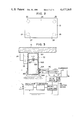
- FIG. 2 is a plan view of a self-levelling device controllable by a method of the present invention
- FIG. 3 is a fragmentary cross-sectional view of a table, a sensor and an air spring of the self-levelling device of FIG. 2, the view being also illustrative of principles of levelling of the table;
- FIG. 4 is a block diagram of an arrangement for controlling four air springs as shown in FIG. 2 with three sensors;
- FIG. 5 is a block diagram of a sensor
- FIG. 6 is a fragmentary cross-sectional view of the table as positionally related to a sensor coil
- FIG. 7 is a graph showing a curve of the impedance of a resonance circuit plotted against variations in the inductance of the sensor coil which defines the impedance;
- FIG. 8 is a block diagram of a controller for controlling valves, such a sensor
- FIG. 9 is a graph showing a relationship between time and variations in table level which is controllable by the controller shown in FIG. 8;
- FIG. 10 is a diagram illustrative of pulses applied to the inlet valve for raising the table according to the level variations shown in FIG. 9;
- FIG. 11 shows pulses for moving the table upwardly and downwardly for equal distances
- FIG. 12 shows variations in table level which correspond to pulses applied for upward and downward movement of the table
- FIG. 13 illustrates variations in table level as controlled by combined pulses for upward and downward table movement
- FIG. 14 shows a pulse for upward table movement and pulses to be combined therewith for downward table movement
- FIG. 15 is illustrative of variations in table level which are caused by pulse combinations shown in FIG. 14;
- FIG. 16 is a program flowchart for operations of the controller
- FIG. 17 is illustrative of table level variations as caused by a plurality of pulses for moving the table upwardly and downwardly;
- FIG. 18 shows table level variations in two divided low-speed regions.
- FIG. 19 illustrates a modified sensor
- a table 21 of a self-levelling device controllable by a method of the present invention is supported at its four corners by air springs 22, 23, 24, and 25.
- Three sensors 26, 27, and 28 are disposed below the table 21 for measuring amounts of displacement or deviation of the table 21 from a reference position.
- the table 21 is shown as supported by one of such sensors 32 which comprises a diaphragm or bellows 321 held against the underside of the table 21, an air chamber 322 supporting the diaphragm 321, and a leg 323 supporting the air chamber 322.
- the air chamber 322 has an inlet port 324 for supplying air under pressure into the air chamber 322, and an outlet port 325 for discharging air out of the air chamber 322.
- the air chamber 322 also includes a partition 326 on which the diaphragm 321 is mounted, the partition 326 having an orifice 327 extending therethrough which has a predetermined diameter.
- An arm 33 projects laterally from the air chamber 332 and has on its upper end one of the sensors 34 spaced a predetermined distance from the lower surface of the table 21.
- the sensor 34 serves to measure a distance between an upper surface of the sensor 34 and the lower surface of the table 21 to a nicety and to deliver information or data as to the measured distance to a control device or controller 35.
- the controller 35 is responsive to such information supplied for determining whether to raise or lower the table 21 and for actuating an outlet valve 36 connected to the outlet port 325 or an inlet valve 37 connected to the inlet port 324.
- the outlet valve 36 When the outlet valve 36 is opened, air is discharged from the air chamber 322 allowing the diaphragm 321 to collapse, whereupon the table 21 is lowered.
- Such operation is effected by the four air springs to keep the table spaced a predetermined level from a floor or base above which the table is disposed.
- the sensor 27 supplied information A indicative of an amount of displacement of the table to the controller 35, which generates pulses A+ and A- for upward and downward movement of the table which are needed for table level adjustment.
- the pulses are applied to an inlet or outlet valve 42 or 43 to open the selected valve to actuate the air spring 24.
- the sensor 27 operates in the same way as described above.
- the sensor 26 serves to detect amounts of displacement of the table at a position midway between the air springs 22, 23 and to cause the controller 35 to produce pulses C+ or C- based on information or data on a detected deviation for actuating the air springs 22, 23 simultaneously to raise or lower the table.
- the air chambers of the air springs 22, 23 are held in fluid communication with each other and connected to a common inlet valve and a common outlet valve.
- one of the sensors described 51 comprises an oscillator 511, a resonance circuit composed of a coil 512 and a capacitor 513 connected in parallel for being supplied with an oscillating current from the oscillator 511, and a rectifier 514 for rectifying a current from the resonance circuit into a direct current.
- An output from the rectifier 514 is delivered over a signal transmission cable 52 to an A/D converter 531 in the controller 35.
- the sensor 51 will operate as follows: The oscillator 511 is energized to produce a signal having a frequency of about 200 KHz and deliver an oscillating current to the resonance circuit, in which the coil 512 may have an inductance of 200 ⁇ H and the capacitor 513 a capacitance of 0.01 ⁇ F, for example.
- the coil 512 is disposed adjacent to the lower surface of the table 21, which is made of magnetic material, or alternatively to a magnetic plate (not shown) attached to the underside of the table 21.
- the impedance of the coil 62 varies.
- the impedance, shown at Z in FIG. 7, of the resonance circuit varies along a curve as shown in FIG. 7 as the inductance L of the coil 512 changes, the curve being symmetrical with the maximum value at a resonance point 71 at the frequency of 200 KHz.
- the impedance of the resonance circuit will be increased as the table 21 moves upwardly, and will be reduced as the table 21 moves downwardly.
- a constant oscillating voltage of 200 KHz is applied to the resonance circuit, a current flowing in the circuit is variable linearly, and a signal obtained by rectifying the current corresponds to a displacement of the table.
- a displacement of a table by about 20 ⁇ can be detected by converting a dc voltage of about 0 to 5 V from the sensor into a corresponding digital signal.
- the controller for processing sensor outputs to control the valves for their opening and closing operation will be described in more detail with reference to FIG. 8.
- the controller converts a dc output voltage signal A from a sensor 801 into a digital signal through an A/D converter 802, and delivers such a digital signal over a bus line 804 under a command from a CPU 803.
- ROMs 805 in which a program is written
- RAM 806 in which control constants are stored
- I/O port 807 for generating outputs for controlling valves.
- the CPU 803 compares data from the sensor 801 with data indicative of a reference position in which the table is to be located, determines whether to open an outlet valve 809 or an inlet valve 800, and produces as output pulses A+ or A- for moving the table upwardly or downwardly.
- Driver circuits 810, 811 are energized by such upward or downward movement pulses A+ or A- for selective application of a voltage as of 24 V to actuate the outlet valve 809 or the inlet valve 808.
- the drivers 810, 811 may be in the form of switching circuits comprising known transistors.
- FIGS. 9 and 10 are illustrative of the way in which the controller shown in FIG. 8 is employed to lift the table from a position 92 below a reference position 91 into a reference region 95 with the reference position 91 therein, in which no level adjustment is necessary.
- the table is initially in the position 92 as shown in FIG. 9.
- the inlet valve When the inlet valve is actuated to be open continuously for a period of 5 sec., as illustrated in FIG. 10, the table is raised to an upper edge 94 of a high-speed region 93.
- the table moves at a lower speed in a low-speed region 96 above the high-speed region 93 to prevent hunting.
- the inlet valve is opened for intermittent intervals of time each comprising t sec. until the table enters the reference region 95, whereupon the inlet valve is de-energized.
- the table can move upwardly smoothly into the desired reference region without hunting.
- the inlet and outlet valves will be actuated in different intervals of time to displace the table upwardly and downwardly for equal distances. Such intervals of time will vary with loads imposed on the table.
- a unit amount of upward or downward movement of the table, or a unit driven distance therefor be constant which corresponds to a single period of time in which the valve is actuated in the low-speed region.
- a test pulse is applied to the inlet and outlet valves while the table is in use, and amounts of upward and downward movement of the table are measured which is caused by the application of the pulse. Data thus obtained is employed to compute intervals of time in which the valves are to be operated and which correspond to unit distances for which to move the table.
- the computed intervals of time are stored as data on constants in the RAM 806 of the controller as shown in FIG. 8.
- FIG. 12 shows variations in the level of the table which occur when determining such constants.
- an upward movement pulse 122 indicated at A+ is applied to raise the table for one step or increment as shown by the curve H, thereby measuring a change in the table level.
- the width of a pulse for moving the table upwardly through a unit distance is computed from the width of the pulse 122 applied and the change in the table level.
- a downward movement pulse 123 indicated at A- is applied to compute the width of a pulse for moving the table downwardly through a unit distance in a similar manner. Data on these pulse widths are stored in the RAM 806 shown in FIG. 8.
- the I/O port generates an upward movement pulse or a downward movement pulse for driving the table for a unit distance.
- Such constant determining operation is performed as desired while the table is in use to determine suitable constants dependent upon the weight of a machine mounted on the table, that is, upon the condition in which the table is used.
- the table can be moved upwardly or downwardly by actuating the inlet or outlet valve with upward or downward movement pulses applied.
- solenoid-operated valves will not be actuated unless the solenoid is supplied with a pulse over a predetermined period of time.
- the inlet valve according to the present invention will be actuated when supplied with a pulse having a width of 50 msec. or more at dc 24 V. If the valve were opened for 50 msec. upon application of a pulse having a width of 50 msec., the table supporting a heavy machine thereon would be raised 100 ⁇ m and lowered 400 ⁇ m, for example. Therefore, where the reference region has a width of about 200 ⁇ m, the table would not be maintained stably in the reference region.
- FIG. 13 To cope with such a problem, combined upward movement and downward movement pulses are applied as shown in FIG. 13 in accordance with the present invention.
- an upward movement pulse A+ is applied for 200 msec. to open the inlet valve for 200 msec.
- a downward movement pulse A- is applied for 50 msec. to actuate the outlet valve for 50 msec.
- About 10 msec. will elapse after the controller has delivered such pulses and before the valves start being actuated.
- such a delayed response time is not large and is negligible, only the pulses being shown with no opening and closing of the valves indicated.
- a control method as illustrated in FIG. 13, in order to be carried out, requires a process for finding an optimum combination of upward and downward movement pulses to be applied one after another with the widths thereof predetermined. Such a process will be described with reference to FIG. 14.
- a pulse having a width of 200 msec. is produced for moving the table upwardly. Then, 300 msec. after such a pulse has been generated, a pulse having a width of 50 msec. is produced for lowering the table. The table is measured for an amount of displacement thereof which will take place about 3 sec. thereafter.
- a similar process will be repeated by applying downward movement pulses having increased widths, such as of 60 msec. and 70 msec. with the upward movement pulse remaining unchanged. Amounts of displacement of the table are plotted against widths of downward movement pulses as shown in FIG. 15. Theoretically, such a relationship as shown in FIG. 15 is utilized to actuate the outlet valve in a manner described above, thus enabling the table to be corrected in displacement regardless of response characteristics of the valve.
- a measurable amount of displacement of the table had a limit of about 20 ⁇ m.
- a unit amount of upward movement of the table was 30 ⁇ m obtained by a combination of an upward movement pulse of 200 msec. and a downward movement pulse of 65 msec.
- a unit amount of downward movement of the table was 30 ⁇ m obtained by a combination of an upward movement pulse of 200 msec. and a downward movement pulse of 110 msec.
- Such unit amounts of upward and downward movement were employed for use in low-speed regions one on each side of the reference region.
- the series of operations is carried out under a program stored in the ROM 805 of the controller of FIG.
- FIG. 16 is a program flowchart for the controller, including the foregoing process. According to the illustrated program, the above process is carried out immediately before the self-levelling device is operated and after the controller has been turned on in order to start actuating the self-levelling device with a variety of machines placed on the table.
- the program flowchart will be described with reference to FIG. 8.
- the program written in the ROM 805 starts being executed, whereupon data on the lengths of upward and downward movement pulses corresponding to unit amounts of upward and downward movement of the table are transferred from the ROM 805 in which the data have been written as standard values to the RAM.
- the CPU reads a data A from the sensor 801, and compares it with a reference position for the table to compute an amount of deviation of the table from the reference position.
- the table on the air springs is normally in the lowermost position, and hence the CPU decides whether the position of the table is in a high-speed region or a low-speed region.
- the inlet valve When the table position is in the high-speed region, the inlet valve is actuated. The program is now back to the LOOP point. A data B from another sensor is then read and the foregoing process is repeated. Similarly, a data C from still another sensor is processed. Then, again, a data A is read. At this time, the result of the foregoing process is reviewed, and when the table enters the low-speed region, the inlet valve is de-energized, and then a single pulse for moving the table upwardly for a unit amount is generated. The width of such a pulse is determined by using the standard data. The foregoing cyclic process will be repeated to lift the table to the reference region.
- the program decides whether the process for determining unit driven distances, that is, unit amounts of upward and downward movement, has been effected.
- each sensor is checked to ascertain whether the table is out of the reference region, and when the table is out of that region, as many upward or downward movement pulses as necessary are applied to return the table to the reference region. Since the foregoing processing is effected by a microcomputer at a speed much higher than the speed at which the air springs respond, the air springs can be regarded as being actuated substantially simultaneously for moving the table upwardly or downwardly.
- FIG. 17 the table is returned from a level 174 or 175 in either one of low-speed regions 170, 173 on both sides of a reference region 171 to the reference region through five increments of driven movement.
- FIG. 18 shows a reference region 181 and a low-speed region 182 disposed downwardly of the reference region 181 and including first and second low-speed regions 184, 183. The table will be moved for different unit distances in the first and second low-speed regions 184, 183. In FIG. 18, the table can be raised at a relatively high speed through the first low-speed region 184 up to the second low-speed region 183, which is smaller in width. Thus, the table can have an increased response as a whole.
- a modified sensor shown in FIG. 19, for use in a control method according to the present invention, serves to detect a table optically.
- a driver circuit 197 energizes light-emitting elements 195, 196 to emit light, which is reflected by mirrors 193, 194 attached to a lower surface of a table 190 and received by a two-dimensional image sensor 191 to detect the degree of inclination of the table 190.
- the two-dimensional image sensor delivers data on the degree by which the table 190 deviates from the horizon to a controller 198 in order to align the table 190 with the horizon.
- Light emitted from the light-emitting element 196 also falls on the mirror 193 on the table as held horizontally at an angle to the horizon and is reflected onto a one-dimensional image sensor 192 which can detect the level of the table based on a deviation of the position where light hits the sensor 192.
- the position of a table can be sensed to a nicety through contactless detection for returning the table to a reference position in much a shorter period of time than with conventional mechanical control arrangements.
- level control for self-levelling devices is effeced by a microcomputer under a relatively simple program.
- the sensor may be replaced with a device for sensing an approaching object through contactless detection based on changes in electrostatic capacity.
- the air spring may be of the suspension type.
- the controller may be operable under different programs. For example, a device may be added under a command from the operator for setting unit driven distances for the table or displaying what is being processed.
- Unit driven distances for which the table is to be moved upwardly and downwardly may be changed as desired.
Abstract
Description
Claims (5)
Applications Claiming Priority (4)
| Application Number | Priority Date | Filing Date | Title |
|---|---|---|---|
| JP14882980A JPS5773248A (en) | 1980-10-23 | 1980-10-23 | Oscillation proof apparatus for air spring |
| JP55-148829 | 1980-10-23 | ||
| JP16117781A JPS5862509A (en) | 1981-10-09 | 1981-10-09 | Controlling method for vibration-absorbing table |
| JP56-161177 | 1981-10-09 |
Publications (1)
| Publication Number | Publication Date |
|---|---|
| US4477045A true US4477045A (en) | 1984-10-16 |
Family
ID=26478897
Family Applications (1)
| Application Number | Title | Priority Date | Filing Date |
|---|---|---|---|
| US06/313,210 Expired - Lifetime US4477045A (en) | 1980-10-23 | 1981-10-20 | Method of controlling a self-levelling device |
Country Status (1)
| Country | Link |
|---|---|
| US (1) | US4477045A (en) |
Cited By (25)
| Publication number | Priority date | Publication date | Assignee | Title |
|---|---|---|---|---|
| EP0206651A2 (en) * | 1985-06-17 | 1986-12-30 | United Kingdom Atomic Energy Authority | Adjustable mirror mountings |
| US4635892A (en) * | 1985-08-19 | 1987-01-13 | Vibrastop, Inc. | Active vibration suppressor |
| DE3718630A1 (en) * | 1986-06-03 | 1987-12-10 | Technical Mfg Corp | METHOD AND DEVICE FOR INSULATING A TABLE TOP FROM MECHANICAL VIBRATIONS |
| US4754713A (en) * | 1985-09-20 | 1988-07-05 | Chatenay Catherine M | Movable platform with adjustable legs |
| US4850261A (en) * | 1986-06-03 | 1989-07-25 | Technical Manufacturing Corporation | Non-contacting electro-pneumatic servo for vibration isolation |
| US4927119A (en) * | 1986-02-24 | 1990-05-22 | Kimball Industries, Inc. | Reversible flow valve for air isolated bases |
| US5060519A (en) * | 1988-02-18 | 1991-10-29 | Tokkyo Kiki Kabushiki Kaisha | Active control precision damping table |
| US5207408A (en) * | 1988-04-11 | 1993-05-04 | Burg Donald E | Stabilized air supported structure |
| US5285995A (en) * | 1992-05-14 | 1994-02-15 | Aura Systems, Inc. | Optical table active leveling and vibration cancellation system |
| US5320047A (en) * | 1992-03-06 | 1994-06-14 | Monarch Hydraulics, Inc. | Desk having self-releveling height adjustment and hydraulic circuit therefor |
| US5322025A (en) * | 1992-05-29 | 1994-06-21 | Steelcase Inc. | Adjustable dual worksurface support |
| US5348265A (en) * | 1988-04-11 | 1994-09-20 | Burg Donald E | Air cushion supported secondary structure |
| US5564662A (en) * | 1994-08-15 | 1996-10-15 | Midmark Corporation | Uneven floor compensating system for surgery tables |
| US5587900A (en) * | 1995-05-23 | 1996-12-24 | Northrop Grumman Corporation | Self leveling independently programmable system |
| DE19628974C1 (en) * | 1996-07-18 | 1997-11-20 | Leica Mikroskopie & Syst | Device for vibration isolation of object wrt. a base |
| US5722513A (en) * | 1995-06-20 | 1998-03-03 | Pentalift Equipment Corporation | Scissor lift |
| US5822813A (en) * | 1995-11-02 | 1998-10-20 | Powell; Tyrone E. | Motion compensated apparatus |
| US5881987A (en) * | 1996-04-02 | 1999-03-16 | Canon Kabushiki Kaisha | Vibration damping apparatus |
| WO1999051452A3 (en) * | 1998-04-07 | 1999-12-02 | P Dennis Mcneely | A suspension and a dynamic load-compensating fluid spring therefor |
| US6286441B1 (en) * | 1999-04-30 | 2001-09-11 | Steelcase Development Corporation | Height adjustable work surface and control therefor |
| US6763774B1 (en) | 2003-02-10 | 2004-07-20 | Boston Whaler, Inc. | Active deck suspension system |
| US20090224444A1 (en) * | 2008-03-04 | 2009-09-10 | Canon Kabushiki Kaisha | Vibration suppression apparatus, exposure apparatus, and method of manufacturing device |
| US20140182400A1 (en) * | 2012-10-19 | 2014-07-03 | Shenzhen China Star Optoelectronics Technology Co., Ltd. | Measuring apparatus and controlling method thereof |
| CN106439402A (en) * | 2016-11-02 | 2017-02-22 | 空气动力学国家重点实验室 | Leveling device |
| US10114352B2 (en) * | 2015-07-01 | 2018-10-30 | Fellowes, Inc. | Variable height platform device |
Citations (5)
| Publication number | Priority date | Publication date | Assignee | Title |
|---|---|---|---|---|
| US2956761A (en) * | 1957-09-12 | 1960-10-18 | Weber Instr Company | Self-levelling and weighing device |
| US3730473A (en) * | 1970-03-19 | 1973-05-01 | Barry Wright Co | Pneumatic self-positioning shock and vibration isolation stabilizing absorber |
| SU414381A1 (en) * | 1971-12-06 | 1974-02-05 | М. Л. Севериновский , А. А. Зарецкий Научно исследовательский институт строительного производства | DEVICE FOR STABILIZATION OF THE HORIZONTAL POSITION OF THE PLATFORM OF THE CONSTRUCTION MACHINE |
| US4057212A (en) * | 1975-08-15 | 1977-11-08 | Barry Wright Corporation | Fluidic vibration isolator |
| US4336917A (en) * | 1979-10-11 | 1982-06-29 | Optimetrix Corporation | Shock and vibration isolation system |
-
1981
- 1981-10-20 US US06/313,210 patent/US4477045A/en not_active Expired - Lifetime
Patent Citations (5)
| Publication number | Priority date | Publication date | Assignee | Title |
|---|---|---|---|---|
| US2956761A (en) * | 1957-09-12 | 1960-10-18 | Weber Instr Company | Self-levelling and weighing device |
| US3730473A (en) * | 1970-03-19 | 1973-05-01 | Barry Wright Co | Pneumatic self-positioning shock and vibration isolation stabilizing absorber |
| SU414381A1 (en) * | 1971-12-06 | 1974-02-05 | М. Л. Севериновский , А. А. Зарецкий Научно исследовательский институт строительного производства | DEVICE FOR STABILIZATION OF THE HORIZONTAL POSITION OF THE PLATFORM OF THE CONSTRUCTION MACHINE |
| US4057212A (en) * | 1975-08-15 | 1977-11-08 | Barry Wright Corporation | Fluidic vibration isolator |
| US4336917A (en) * | 1979-10-11 | 1982-06-29 | Optimetrix Corporation | Shock and vibration isolation system |
Cited By (34)
| Publication number | Priority date | Publication date | Assignee | Title |
|---|---|---|---|---|
| EP0206651A2 (en) * | 1985-06-17 | 1986-12-30 | United Kingdom Atomic Energy Authority | Adjustable mirror mountings |
| EP0206651A3 (en) * | 1985-06-17 | 1988-07-20 | United Kingdom Atomic Energy Authority | Adjustable mirror mountings |
| US4635892A (en) * | 1985-08-19 | 1987-01-13 | Vibrastop, Inc. | Active vibration suppressor |
| US4754713A (en) * | 1985-09-20 | 1988-07-05 | Chatenay Catherine M | Movable platform with adjustable legs |
| US4927119A (en) * | 1986-02-24 | 1990-05-22 | Kimball Industries, Inc. | Reversible flow valve for air isolated bases |
| DE3718630A1 (en) * | 1986-06-03 | 1987-12-10 | Technical Mfg Corp | METHOD AND DEVICE FOR INSULATING A TABLE TOP FROM MECHANICAL VIBRATIONS |
| US4730541A (en) * | 1986-06-03 | 1988-03-15 | Technical Manufacturing Corporation | Non contacting electro-pneumatic servo for vibration isolation |
| US4850261A (en) * | 1986-06-03 | 1989-07-25 | Technical Manufacturing Corporation | Non-contacting electro-pneumatic servo for vibration isolation |
| US5060519A (en) * | 1988-02-18 | 1991-10-29 | Tokkyo Kiki Kabushiki Kaisha | Active control precision damping table |
| US5207408A (en) * | 1988-04-11 | 1993-05-04 | Burg Donald E | Stabilized air supported structure |
| US5348265A (en) * | 1988-04-11 | 1994-09-20 | Burg Donald E | Air cushion supported secondary structure |
| US5320047A (en) * | 1992-03-06 | 1994-06-14 | Monarch Hydraulics, Inc. | Desk having self-releveling height adjustment and hydraulic circuit therefor |
| US5285995A (en) * | 1992-05-14 | 1994-02-15 | Aura Systems, Inc. | Optical table active leveling and vibration cancellation system |
| US5322025A (en) * | 1992-05-29 | 1994-06-21 | Steelcase Inc. | Adjustable dual worksurface support |
| US5564662A (en) * | 1994-08-15 | 1996-10-15 | Midmark Corporation | Uneven floor compensating system for surgery tables |
| US5587900A (en) * | 1995-05-23 | 1996-12-24 | Northrop Grumman Corporation | Self leveling independently programmable system |
| US5722513A (en) * | 1995-06-20 | 1998-03-03 | Pentalift Equipment Corporation | Scissor lift |
| US5822813A (en) * | 1995-11-02 | 1998-10-20 | Powell; Tyrone E. | Motion compensated apparatus |
| US5881987A (en) * | 1996-04-02 | 1999-03-16 | Canon Kabushiki Kaisha | Vibration damping apparatus |
| DE19628974C1 (en) * | 1996-07-18 | 1997-11-20 | Leica Mikroskopie & Syst | Device for vibration isolation of object wrt. a base |
| US6042079A (en) * | 1996-07-18 | 2000-03-28 | Mikroskopie Und Systeme Gmbh | Device for vibration isolation |
| WO1999051452A3 (en) * | 1998-04-07 | 1999-12-02 | P Dennis Mcneely | A suspension and a dynamic load-compensating fluid spring therefor |
| US6217010B1 (en) * | 1998-04-07 | 2001-04-17 | Mcneely P. Dennis | Suspension and a dynamic load-compensating fluid spring therefor |
| US6286441B1 (en) * | 1999-04-30 | 2001-09-11 | Steelcase Development Corporation | Height adjustable work surface and control therefor |
| US6763774B1 (en) | 2003-02-10 | 2004-07-20 | Boston Whaler, Inc. | Active deck suspension system |
| EP2098750A3 (en) * | 2008-03-04 | 2010-06-23 | Canon Kabushiki Kaisha | Vibration suppression apparatus, exposure apparatus, and method of manufacturing device |
| US20090224444A1 (en) * | 2008-03-04 | 2009-09-10 | Canon Kabushiki Kaisha | Vibration suppression apparatus, exposure apparatus, and method of manufacturing device |
| US20140182400A1 (en) * | 2012-10-19 | 2014-07-03 | Shenzhen China Star Optoelectronics Technology Co., Ltd. | Measuring apparatus and controlling method thereof |
| US9151643B2 (en) * | 2012-10-19 | 2015-10-06 | Shenzhen China Star Optoelectronics Technology Co., Ltd. | Measuring apparatus and controlling method thereof |
| US10114352B2 (en) * | 2015-07-01 | 2018-10-30 | Fellowes, Inc. | Variable height platform device |
| US10649422B2 (en) | 2015-07-01 | 2020-05-12 | Fellowes, Inc. | Variable height platform device |
| US11054797B2 (en) | 2015-07-01 | 2021-07-06 | Fellowes, Inc. | Variable height platform device |
| US11526141B2 (en) | 2015-07-01 | 2022-12-13 | Fellowes, Inc. | Variable height platform device |
| CN106439402A (en) * | 2016-11-02 | 2017-02-22 | 空气动力学国家重点实验室 | Leveling device |
Similar Documents
| Publication | Publication Date | Title |
|---|---|---|
| US4477045A (en) | Method of controlling a self-levelling device | |
| US4712470A (en) | Method and apparatus for compensating the variable weight of a mass acting on a hydraulic drive, in particular for the upright drive cylinder of a lapping machine | |
| US5461564A (en) | Apparatus and method for calibrating vehicle ride height | |
| US5060519A (en) | Active control precision damping table | |
| US5267466A (en) | Apparatus and method for calibrating a suspension control module | |
| US6192299B1 (en) | Method of measuring operation characteristic of proportional electromagnetic control valve, method of controlling operation of hydraulic cylinder, and method of modifying operation characteristic of proportional electromagnetic control valve | |
| US8969750B2 (en) | Method and apparatus for controlling electrode arms of a welding device | |
| JPH08198584A (en) | Method of unattended operation of crane and its device | |
| EP0260138B1 (en) | Servo control system | |
| US5179516A (en) | Variation control circuit having a displacement detecting function | |
| EP1547893B1 (en) | Method and apparatus for controlling lift of a structural object | |
| WO1989011120A1 (en) | Compliant motion servo | |
| US20200156518A1 (en) | Smart Automatic Seat Height Adjustment System | |
| EP0195820B1 (en) | Method of mounting electronic parts and an apparatus therefor | |
| CA2102360C (en) | Method and device for controlling, checking or optimizing pressure of cushion pin cylinders of press by discharging fluid or initial pressure | |
| EP0409829A1 (en) | Calibration of a high regulating device in a vehicle filled with air suspension. | |
| US5645210A (en) | High speed bonding tool contact detector | |
| US5635848A (en) | Method and system for controlling high-speed probe actuators | |
| US6042079A (en) | Device for vibration isolation | |
| US5869918A (en) | Actuator which controls voltage level and voltage level increase time of an electromechanical converting element drive signal | |
| JPH0225156B2 (en) | ||
| KR20040047628A (en) | Method for picking semiconductor chips from a foil | |
| JPH10192764A (en) | Coating device | |
| JPS6181808A (en) | Vehicle height control method | |
| JP2004524154A (en) | Controller for unbalanced weight and adjustment of ground compactors |
Legal Events
| Date | Code | Title | Description |
|---|---|---|---|
| AS | Assignment |
Owner name: SHOWA ELECTRIC WIRE & CABLE CO., LTD., 2-1-1 ODASA Free format text: ASSIGNMENT OF ASSIGNORS INTEREST.;ASSIGNORS:KARASAWA, KOHICHI;ITOH, TAKEO;KOIZUMI, HUMIHITO;AND OTHERS;REEL/FRAME:003973/0162 Effective date: 19820324 |
|
| STCF | Information on status: patent grant |
Free format text: PATENTED CASE |
|
| FEPP | Fee payment procedure |
Free format text: PAYOR NUMBER ASSIGNED (ORIGINAL EVENT CODE: ASPN); ENTITY STATUS OF PATENT OWNER: LARGE ENTITY |
|
| FPAY | Fee payment |
Year of fee payment: 4 |
|
| FPAY | Fee payment |
Year of fee payment: 8 |
|
| FEPP | Fee payment procedure |
Free format text: PAYER NUMBER DE-ASSIGNED (ORIGINAL EVENT CODE: RMPN); ENTITY STATUS OF PATENT OWNER: LARGE ENTITY Free format text: PAYOR NUMBER ASSIGNED (ORIGINAL EVENT CODE: ASPN); ENTITY STATUS OF PATENT OWNER: LARGE ENTITY |
|
| FPAY | Fee payment |
Year of fee payment: 12 |