US4523384A - Method and apparatus for measuring deviations in vehicle bodies or frames - Google Patents
Method and apparatus for measuring deviations in vehicle bodies or frames Download PDFInfo
- Publication number
- US4523384A US4523384A US06/592,250 US59225084A US4523384A US 4523384 A US4523384 A US 4523384A US 59225084 A US59225084 A US 59225084A US 4523384 A US4523384 A US 4523384A
- Authority
- US
- United States
- Prior art keywords
- measuring
- beams
- frame
- vehicle
- transverse beams
- Prior art date
- Legal status (The legal status is an assumption and is not a legal conclusion. Google has not performed a legal analysis and makes no representation as to the accuracy of the status listed.)
- Expired - Lifetime
Links
Images


Classifications
-
- G—PHYSICS
- G01—MEASURING; TESTING
- G01B—MEASURING LENGTH, THICKNESS OR SIMILAR LINEAR DIMENSIONS; MEASURING ANGLES; MEASURING AREAS; MEASURING IRREGULARITIES OF SURFACES OR CONTOURS
- G01B5/00—Measuring arrangements characterised by the use of mechanical techniques
- G01B5/20—Measuring arrangements characterised by the use of mechanical techniques for measuring contours or curvatures
- G01B5/207—Measuring arrangements characterised by the use of mechanical techniques for measuring contours or curvatures using a plurality of fixed, simultaneously operating transducers
Definitions
- This invention relates to a measuring method and to a measuring device for measuring deviation in the form of vehicle bodies or frames, often in connection with inspection of damage or alignment of deformed vehicles.
- the measuring method is carried out in such a way that four gripping means are clamped in four undamaged reference points located in the middle section of the vehicle.
- the gripping means are in turn combined with a measuring frame which is oriented in a plane parallel to the ground plane of the vehicle.
- a measuring beam provided with the necessary measuring means is then quick coupled parallelly to the ground plane of the measuring frame and the vehicle so that all the other reference points of the vehicle can be rapidly controlled by measurement.
- the measuring frame of the present invention can be dismantled in short sections, and can be easily accommodated in a usual suitcase.
- the measuring frame is further provided with a telescopic measuring rod by which the necessary crosswise measurements can be rapidly carried out.
- the invention is able to detect small deformations (about 80% of all cases) that are rarely put onto a levelling bench or the like for reasons of time and costs.
- this invention creates a very rapid, cheap and portable diagnostic instrument which is of a special interest for insurance companies, trading companies, research laboratories, police etc., which are often not directly engaged in motor car repair activities but which still need to evaluate vehicles in a simple, quick and cheap way.
- vehicle body frame measurements are typically carried out by means of heavy, bulky and expensive measuring frames or measuring jigs, which are normally not engaged in instances of small deformations or suspicion of a possible deformation.
- Vehicle bodies and frames are often not measured in instances of small deviation because at present there is lacking a light, portable, quickly adjustable and simple measuring device which can provide the desired measuring result within some minutes and which is therefore not prevented by high working costs.
- a usual simple crosswise measurement there is a further risk of an erroneous diagnosis on account of the fact that the measurement, as a rule, is carried out only in two dimensions. Therefore this prior method is not sufficiently safe.
- the present invention is directed to a method and apparatus for measuring deviation in vehicle bodies and frames in order to determine the extent of damage, whether a certain vehicle can be repaired and if a vehicle can be considered as aligned in a traffic-safe and acceptable manner.
- a specially constructed gripping means is clamped in four undamaged reference points in the middle section of the vehicle so that two transverse beams can be quick coupled to said gripping means.
- the transverse beams will then form together with a longitudinal center beam an H-shaped measuring frame which is in a plane parallel to the ground plane of the vehicle.
- a measuring beam is then quick coupled with movable attaching means to said transverse beams so that the measuring beam can be given an arbitrary orientation in a plane parallel to the ground plane of the vehicle.
- the measuring beam of the present invention has been provided with a measuring means for vertical measurement perpendicular to the ground plane of the vehicle.
- Crosswise measurement can then be carried out in such a way that a telescopic measuring rod with a measuring tip in one end and a means for quick coupling with a ball joint in the other end is attached to fixed balls which have been adapted to the transverse beams and to the center beam.
- One essential advantage of this invention is that it takes very little space under the vehicle and leaves the floor below free so that an operator is able to work with the car in an upright position without disturbing obstacles.
- Other advantages of the present invention are that the complete device may weigh as little as about 15 kg, as it is made of aluminium, and the device can be simply accommodated and transported in a usual suitcase.
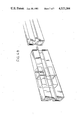
- FIG. 1 is a perspective view of the measuring frame of the present invention
- FIG. 2 is a sectional view of a pole attachment, transverse beam and measuring beam
- FIG. 3 shows a gripping means with pole attachment
- FIG. 4 shows a section of the gripping means
- FIG. 5 shows the measuring means with telescopic poles and measuring tips
- FIG. 6A shows jointing means for beams
- FIG. 6B shows an alternate jointing means for beams.
- Transverse beams 1 and 2 are made of an aluminium profile with grooves 37 for simple fitting of mounting irons 34 and 35, and have threaded holes in which different mounting and screwing operations can be easily carried out.
- a center beam 3 with the same profile as the transverse beams 1 and 2 is shown. The center beam is placed at the center on top of the transverse beams 1 and 2 with the aid of locking irons 27 and locking screw 28, not shown, the former being provided with a taper guide 29 in order that the center beam might be clamped to the two transverse beams 1 and 2 and form a fixed frame for the whole measuring device.
- a measuring beam 4 is adapted below the beams 1 and 2 by means of two quick couplings on attachments 11 so that the measuring beam will hang under the whole device.
- the attachments 11 for the measuring beam can be pushed and locked to an arbitrary position along the beams 1 and 2.
- the quick coupling 23 and 25 is fixed to a screw 24, which can be locked to an attaching iron 35, which can slide in the profile of the beams 1 and 2.
- the quick coupling 23 and 25 is not shown with respect to its function.
- a measuring rod 5 can be rapidly connected by means of a ball joint 17 to the beam 1 with a quick coupling 16 intended for balls.
- the measuring rod 5 is of a telescopic type and is provided with a measuring tip 18 and a graduated scale 57.
- Each beam 1 and 2 is provided with two pole feet 6, which can be locked by means of mounting iron 34 in an arbitrary position along the beams 1 and 2 by a locking screw 31. All pole feet 6 are provided with pole holes 38 and locking screw 30 for vertical adjustment of the pole 7 which is provided with a graduated scale 36.
- a clamp 8 can be attached to the pole 7 via a quick coupling 32.
- a gripping means 9 is then articulatedly adapted to the clamp 8 by means of two joints 33 and consequently to the beams 1 and 2.
- the pole feet 6 are provided with pointers 19 indicating position and showing the position of the foot along a graduated scale 20 on the beams 1 and 2.
- the gripping means 9 is provided with at least three gripping clutches 10 for clamping to one of the reference points
- the measuring beam 4 is provided with an attachment 12 for the measuring tip with a locking screw 54.
- a telescopic pole 13 provided with a measuring tip 14 and a graduated scale 57 is mounted on the attachment 12.
- the center beam 3 is on its upper side provided with an adjustable reference ball 15 which can be locked to the beam 3 by means of a locking screw not shown and mounting irons in the beam groove.
- the measuring beam 4 can via the attachment 11 be locked to the beams 1 and 2, with locking screw 22, the position being indicated with a pointer 21 along the scale 20.
- the beams 1, 2 and 3 can be provided with end sections 26 for protection of the frail beam ends.
- the gripping means 9 is shown in section.
- the means 9 consists of an adjusting screw 40 and a sleeve 41 within which a piston 43 can slide.
- a cylinder 42 is rigidly connected to the sleeve 41 by means of a locking screw 45.
- the screw 40 can be turned in a central hole of the cylinder 42 and is locked to it by means of a locking ring 44.
- the cylinder 42 and the piston 43 show two semi-circular concave surfaces 46 and 47 which can move axially relative to each other when the screw 40 is turned.
- the screw 40 then moves in a threaded central hole 49 of the piston 43.
- At least three gripping clutches 10 with double balls are fitted into the concave surfaces 46 and 47 so that the gripping clutches 10 are turned in axial direction when the screw is turned and the surfaces 46 and 47 move axially relative to each other.
- FIG. 5 shows the telescopic measuring rod 5 provided with locking rings 52 and double measuring tips 18 as well as an angle bracket 51. Moreover, the attachment 12 for the measuring beam with locking screw 54 and the pole 13 for the measuring tip of a telescopic type with locking rings 53 are shown. The measuring tip 14 is mounted on the pole 13 by means of a locking ring 55 and an angle bracket 56.
- the angle bracket 56 is also provided with V-shaped grooves at an angle of 45° for locking the measuring tip 14 which can thus be adjusted in 45° and 90° relative to the measuring pole 13.
- the measuring rod 5 and the measuring pole 13 can be given the same design with three different angular settings.
- FIG. 6A shows the principle of jointing a beam 3 along the section 60.
- a jointing iron 64 has been screwed onto the left beam part with a locking screw 68.
- the jointing iron is further provided with a conical guide 66 so that the right beam portion is guided into position when the locking screw 61 is tightened.
- the beam 4 can also be jointed along a section 62 by means of a jointing iron 65 not shown which is locked by a locking screw 69.
- the jointing iron 65 is then provided with a guide groove 67 not shown and is locked by the locking screw 63.
- the reference ball 15 can be replaced with a shaft around which the measuring rod in the form of a beam can be brought into a rotatable relation to said shaft and then be turned in a ground plane.
- the beam can then be provided with a measuring tip of the same type as the measuring beam 4, and it is then also possible to carry out a height measurement.
- the gripping means 9 can be given another design so that the concave surfaces 46 and 47 and the cooperating balls 48 change positions.
- the diameter of the gripping means can be considerably reduced in this way.
- the concave and convex joint surfaces can with advantage be coated with a film of rubber or a similar material to get a soft motion of the gripping clutches without play.
- the joint 60 has been provided with a quick coupling.
- two reference points symmetrically located on each side of the center line of the vehicle are localized and the vehicle is hoisted up to a suitable working height with the weight left on all four wheels.
- All the joints of the measuring device are mounted and four loose gripping means 9 are secured to the selected reference points.
- the transverse beams 1 and 2 with loose pole feet 6 are then quick coupled to the gripping means with the transverse beams hanging loosely under the vehicle.
- the pole feet are then adjusted so that these are symmetrically placed on the transverse beams before the pole feet are locked. This is made by controlling the position pointers 19 relative to the graduated scale 20.
- poles 7 are controlled so that these are adjusted to the same height and that this adjustment is suitable with respect to the chassis of the car.
- the center beam 3 is then positioned exactly in the center line of the car by the scales 20 being read.
- the measuring beam 4 is then pressed on with two quick couplings and the attachments 11 are adjusted so that the measuring beam is positioned straight below the reference point to be checked. It is an advantage if one of the attachments 11 can be placed centrally on the center line of the vehicle but this is not necessary. It is then started with a fresh point and the attachment 12 and the telescopic pole 13 are adjusted so that the measuring tip 14 is in contact with the reference point. All the parts of the measuring beam are then locked and reading of height can be carried out on the scale 57 and angle reading on the scales 20 on the transverse beams 1 and 2. One of these can thus have been adjusted in advance to 0 by the location of the measuring beam on the center line. Length reading is then carried out on scale 20 of the measuring beam 4. The position of the reference point in the ground plane has now been obtained in the form of a direct length, and one or two measures of the scales 20 on the transverse beams which in principle give the angle relative to the center line.
- the corresponding reference point on the other side is measured for control in the same way and the difference in resulting readings is a measure of the displacement. Height difference and lateral and longitudinal displacements can then be easily calculated.
- An alignment chart can with advantage be prepared for direct reading of the result in mm.
- the measuring rod 5 for the direct measurement, the reference ball 15 being used.
- the whole measurement procedure can be finished in a fraction of one working hour even if several points must be checked.
- a certain reference point can be quickly checked by means of finished data sheet by adjusting certain values on the scales. Therefore the device can also be used as a comfortable and quick measuring instrument.
Abstract
Description
Claims (12)
Priority Applications (1)
| Application Number | Priority Date | Filing Date | Title |
|---|---|---|---|
| US06/592,250 US4523384A (en) | 1984-03-22 | 1984-03-22 | Method and apparatus for measuring deviations in vehicle bodies or frames |
Applications Claiming Priority (1)
| Application Number | Priority Date | Filing Date | Title |
|---|---|---|---|
| US06/592,250 US4523384A (en) | 1984-03-22 | 1984-03-22 | Method and apparatus for measuring deviations in vehicle bodies or frames |
Publications (1)
| Publication Number | Publication Date |
|---|---|
| US4523384A true US4523384A (en) | 1985-06-18 |
Family
ID=24369924
Family Applications (1)
| Application Number | Title | Priority Date | Filing Date |
|---|---|---|---|
| US06/592,250 Expired - Lifetime US4523384A (en) | 1984-03-22 | 1984-03-22 | Method and apparatus for measuring deviations in vehicle bodies or frames |
Country Status (1)
| Country | Link |
|---|---|
| US (1) | US4523384A (en) |
Cited By (16)
| Publication number | Priority date | Publication date | Assignee | Title |
|---|---|---|---|---|
| US4608760A (en) * | 1985-07-15 | 1986-09-02 | Connie Franks | Frame alignment indicator |
| US4689888A (en) * | 1986-10-22 | 1987-09-01 | Chief Automotive Systems, Inc. | Measuring device for use with automotive frame straightening equipment |
| FR2596508A1 (en) * | 1986-03-25 | 1987-10-02 | Blackhawk Sa | Measurement jig for installation for straightening chassis of vehicles |
| US4731936A (en) * | 1985-10-16 | 1988-03-22 | Chief Automotive Systems, Inc. | Gauging system for vehicle alignment equipment |
| US4891889A (en) * | 1987-05-05 | 1990-01-09 | Garda Impianti S.R.L. | Apparatus for measure and/or check the position and orientation of characteristic spots or areas in structures, particularly in motor-vehicle bodies |
| US4922623A (en) * | 1985-10-16 | 1990-05-08 | Chief Automotive Systems, Inc. | Gauging system for vehicle alignment equipment |
| US5014442A (en) * | 1990-02-07 | 1991-05-14 | Hein-Werner Corporation | Universal measuring system |
| US5507101A (en) * | 1992-07-20 | 1996-04-16 | Mason; James H. | Vehicle alignment gauging apparatus |
| US5647139A (en) * | 1995-05-31 | 1997-07-15 | Richardson; John T. | Universal vehicle gauges |
| US20030131490A1 (en) * | 2002-01-17 | 2003-07-17 | Hakan Johansson | Measuring device |
| US6598308B1 (en) * | 1997-11-28 | 2003-07-29 | Jne Ab | Measuring system |
| US20030150124A1 (en) * | 2000-05-02 | 2003-08-14 | Mason James Herbert | Datum point adaptor for vehicle gauging apparatus |
| US20100088909A1 (en) * | 2008-10-09 | 2010-04-15 | Robert Bosch Gmbh | Vehicle drive axis alignment device |
| CN106052530A (en) * | 2016-07-11 | 2016-10-26 | 华侨大学 | Sea abrasion groove geometric form measurement apparatus and method |
| CN106091992A (en) * | 2016-08-23 | 2016-11-09 | 中冶陕压重工设备有限公司 | Plane milling and boring machine bed ways parallelism detecting device and detection method |
| US20180306579A1 (en) * | 2015-10-23 | 2018-10-25 | Richard BRYCE | H-shaped spirit level |
Citations (5)
| Publication number | Priority date | Publication date | Assignee | Title |
|---|---|---|---|---|
| US31000A (en) * | 1860-12-18 | Henry essex | ||
| US4098003A (en) * | 1976-11-23 | 1978-07-04 | Celette S.A., Vienne | Distortion detection device, notably for motor vehicle frames |
| US4207681A (en) * | 1976-04-26 | 1980-06-17 | Applied Power Inc. | Vehicle measuring bridge |
| US4342154A (en) * | 1979-06-05 | 1982-08-03 | Applied Power Inc. | Measuring bridge |
| US4479305A (en) * | 1982-03-12 | 1984-10-30 | Applied Power Inc. | Measuring bridge |
-
1984
- 1984-03-22 US US06/592,250 patent/US4523384A/en not_active Expired - Lifetime
Patent Citations (5)
| Publication number | Priority date | Publication date | Assignee | Title |
|---|---|---|---|---|
| US31000A (en) * | 1860-12-18 | Henry essex | ||
| US4207681A (en) * | 1976-04-26 | 1980-06-17 | Applied Power Inc. | Vehicle measuring bridge |
| US4098003A (en) * | 1976-11-23 | 1978-07-04 | Celette S.A., Vienne | Distortion detection device, notably for motor vehicle frames |
| US4342154A (en) * | 1979-06-05 | 1982-08-03 | Applied Power Inc. | Measuring bridge |
| US4479305A (en) * | 1982-03-12 | 1984-10-30 | Applied Power Inc. | Measuring bridge |
Cited By (24)
| Publication number | Priority date | Publication date | Assignee | Title |
|---|---|---|---|---|
| US4608760A (en) * | 1985-07-15 | 1986-09-02 | Connie Franks | Frame alignment indicator |
| US4731936A (en) * | 1985-10-16 | 1988-03-22 | Chief Automotive Systems, Inc. | Gauging system for vehicle alignment equipment |
| US4922623A (en) * | 1985-10-16 | 1990-05-08 | Chief Automotive Systems, Inc. | Gauging system for vehicle alignment equipment |
| FR2596508A1 (en) * | 1986-03-25 | 1987-10-02 | Blackhawk Sa | Measurement jig for installation for straightening chassis of vehicles |
| US4689888A (en) * | 1986-10-22 | 1987-09-01 | Chief Automotive Systems, Inc. | Measuring device for use with automotive frame straightening equipment |
| US4891889A (en) * | 1987-05-05 | 1990-01-09 | Garda Impianti S.R.L. | Apparatus for measure and/or check the position and orientation of characteristic spots or areas in structures, particularly in motor-vehicle bodies |
| US5014442A (en) * | 1990-02-07 | 1991-05-14 | Hein-Werner Corporation | Universal measuring system |
| US5507101A (en) * | 1992-07-20 | 1996-04-16 | Mason; James H. | Vehicle alignment gauging apparatus |
| EP0746743A1 (en) * | 1992-07-20 | 1996-12-11 | MASON, James Herbert | Vehicle alignment gauging apparatus |
| EP0746743A4 (en) * | 1992-07-20 | 1997-11-12 | Mason James H | Vehicle alignment gauging apparatus |
| US5647139A (en) * | 1995-05-31 | 1997-07-15 | Richardson; John T. | Universal vehicle gauges |
| US6598308B1 (en) * | 1997-11-28 | 2003-07-29 | Jne Ab | Measuring system |
| US20030150124A1 (en) * | 2000-05-02 | 2003-08-14 | Mason James Herbert | Datum point adaptor for vehicle gauging apparatus |
| US7024788B2 (en) | 2000-05-02 | 2006-04-11 | James Herbert Mason | Datum point adaptor for vehicle gauging apparatus |
| US20030131490A1 (en) * | 2002-01-17 | 2003-07-17 | Hakan Johansson | Measuring device |
| US6769192B2 (en) | 2002-01-17 | 2004-08-03 | Jne Ab | Measuring device |
| US20100088909A1 (en) * | 2008-10-09 | 2010-04-15 | Robert Bosch Gmbh | Vehicle drive axis alignment device |
| US7908760B2 (en) * | 2008-10-09 | 2011-03-22 | Robert Bosch Gmbh | Vehicle drive axis alignment device |
| US20180306579A1 (en) * | 2015-10-23 | 2018-10-25 | Richard BRYCE | H-shaped spirit level |
| US10809060B2 (en) * | 2015-10-23 | 2020-10-20 | Richard BRYCE | H-shaped spirit level |
| CN106052530A (en) * | 2016-07-11 | 2016-10-26 | 华侨大学 | Sea abrasion groove geometric form measurement apparatus and method |
| CN106052530B (en) * | 2016-07-11 | 2018-08-10 | 华侨大学 | Marine abrasion slot geometric shape measuring device and method |
| CN106091992A (en) * | 2016-08-23 | 2016-11-09 | 中冶陕压重工设备有限公司 | Plane milling and boring machine bed ways parallelism detecting device and detection method |
| CN106091992B (en) * | 2016-08-23 | 2018-09-11 | 中冶陕压重工设备有限公司 | Plane milling and boring machine bed ways parallelism detecting device and detection method |
Similar Documents
| Publication | Publication Date | Title |
|---|---|---|
| US4523384A (en) | Method and apparatus for measuring deviations in vehicle bodies or frames | |
| DE4403901B4 (en) | Device for acquiring three-dimensional coordinates | |
| CA1067382A (en) | Apparatus for reforming and straightening vehicles | |
| EP0763708B1 (en) | Coordinate measuring machine | |
| JPH0311933B2 (en) | ||
| US4242803A (en) | Equipment unit for checking deformations of a vehicle body | |
| US4557127A (en) | Motor vehicle body repair bench | |
| CN108072489B (en) | Rotary dynamic balance type centroid measuring instrument and centroid measuring method | |
| US4408399A (en) | Wheel alignment gauge | |
| US4498242A (en) | Device for position-checking of the shock-absorber heads of a front vehicle suspension system | |
| EP0113906B1 (en) | Method for measuring deformations of vehicle frames or bodies and measuring frame for performing that method | |
| JPH0785003B2 (en) | Linear displacement measuring device | |
| US5890300A (en) | Coordinate measuring apparatus having a probe movably journalled via several rotational axes | |
| US4271599A (en) | Wheel camber and castor measurement apparatus | |
| EP0922927B1 (en) | Measuring device for vehicles | |
| US6591218B1 (en) | Process for determining the alignment of a cylindrical body with respect to a reference direction | |
| GB2112522A (en) | Coordinate measuring machine | |
| CA1310488C (en) | Vehicle frame measuring bridge including spring actuated telescoping legs | |
| US4640015A (en) | Macpherson strut alignment gauge and straightening apparatus | |
| DE4447907B4 (en) | Coordinate measuring machine for measuring three-dimensional coordinates | |
| GB2091888A (en) | A testing unit for crash barriers | |
| EP3108217A1 (en) | Measuring instrument and measuring method | |
| DE10319711B4 (en) | Method for high-precision dimensional measurement of measurement objects | |
| JPS6212441B2 (en) | ||
| GB2080954A (en) | Attaching a measuring table to the base frame of a coordinate measuring machine |
Legal Events
| Date | Code | Title | Description |
|---|---|---|---|
| AS | Assignment |
Owner name: HEIN-WERNER CORPORATION, 1005 PERKINS AVENUE, WAUK Free format text: ASSIGNMENT OF ASSIGNORS INTEREST.;ASSIGNOR:APPLIED POWER INC., A WI CORP;REEL/FRAME:004725/0472 Effective date: 19870331 |
|
| FPAY | Fee payment |
Year of fee payment: 4 |
|
| FPAY | Fee payment |
Year of fee payment: 8 |
|
| FEPP | Fee payment procedure |
Free format text: PAYOR NUMBER ASSIGNED (ORIGINAL EVENT CODE: ASPN); ENTITY STATUS OF PATENT OWNER: LARGE ENTITY |
|
| FEPP | Fee payment procedure |
Free format text: PETITION RELATED TO MAINTENANCE FEES FILED (ORIGINAL EVENT CODE: PMFP); ENTITY STATUS OF PATENT OWNER: LARGE ENTITY |
|
| FEPP | Fee payment procedure |
Free format text: PAYER NUMBER DE-ASSIGNED (ORIGINAL EVENT CODE: RMPN); ENTITY STATUS OF PATENT OWNER: LARGE ENTITY Free format text: PAYOR NUMBER ASSIGNED (ORIGINAL EVENT CODE: ASPN); ENTITY STATUS OF PATENT OWNER: LARGE ENTITY |
|
| FEPP | Fee payment procedure |
Free format text: PAT HLDR NO LONGER CLAIMS SMALL ENT STAT AS SMALL BUSINESS (ORIGINAL EVENT CODE: LSM2); ENTITY STATUS OF PATENT OWNER: LARGE ENTITY |
|
| REMI | Maintenance fee reminder mailed | ||
| FPAY | Fee payment |
Year of fee payment: 12 |
|
| SULP | Surcharge for late payment | ||
| FP | Lapsed due to failure to pay maintenance fee |
Effective date: 19970518 |
|
| PRDP | Patent reinstated due to the acceptance of a late maintenance fee |
Effective date: 19981204 |
|
| STCF | Information on status: patent grant |
Free format text: PATENTED CASE |