US4527675A - Oil type damper - Google Patents
Oil type damper Download PDFInfo
- Publication number
- US4527675A US4527675A US06/601,899 US60189984A US4527675A US 4527675 A US4527675 A US 4527675A US 60189984 A US60189984 A US 60189984A US 4527675 A US4527675 A US 4527675A
- Authority
- US
- United States
- Prior art keywords
- oil
- housing
- hollow shaft
- rotator
- flexible membrane
- Prior art date
- Legal status (The legal status is an assumption and is not a legal conclusion. Google has not performed a legal analysis and makes no representation as to the accuracy of the status listed.)
- Expired - Fee Related
Links
Images
Classifications
-
- F—MECHANICAL ENGINEERING; LIGHTING; HEATING; WEAPONS; BLASTING
- F16—ENGINEERING ELEMENTS AND UNITS; GENERAL MEASURES FOR PRODUCING AND MAINTAINING EFFECTIVE FUNCTIONING OF MACHINES OR INSTALLATIONS; THERMAL INSULATION IN GENERAL
- F16D—COUPLINGS FOR TRANSMITTING ROTATION; CLUTCHES; BRAKES
- F16D57/00—Liquid-resistance brakes; Brakes using the internal friction of fluids or fluid-like media, e.g. powders
-
- F—MECHANICAL ENGINEERING; LIGHTING; HEATING; WEAPONS; BLASTING
- F16—ENGINEERING ELEMENTS AND UNITS; GENERAL MEASURES FOR PRODUCING AND MAINTAINING EFFECTIVE FUNCTIONING OF MACHINES OR INSTALLATIONS; THERMAL INSULATION IN GENERAL
- F16F—SPRINGS; SHOCK-ABSORBERS; MEANS FOR DAMPING VIBRATION
- F16F9/00—Springs, vibration-dampers, shock-absorbers, or similarly-constructed movement-dampers using a fluid or the equivalent as damping medium
- F16F9/10—Springs, vibration-dampers, shock-absorbers, or similarly-constructed movement-dampers using a fluid or the equivalent as damping medium using liquid only; using a fluid of which the nature is immaterial
- F16F9/12—Devices with one or more rotary vanes turning in the fluid any throttling effect being immaterial, i.e. damping by viscous shear effect only
-
- F—MECHANICAL ENGINEERING; LIGHTING; HEATING; WEAPONS; BLASTING
- F16—ENGINEERING ELEMENTS AND UNITS; GENERAL MEASURES FOR PRODUCING AND MAINTAINING EFFECTIVE FUNCTIONING OF MACHINES OR INSTALLATIONS; THERMAL INSULATION IN GENERAL
- F16F—SPRINGS; SHOCK-ABSORBERS; MEANS FOR DAMPING VIBRATION
- F16F9/00—Springs, vibration-dampers, shock-absorbers, or similarly-constructed movement-dampers using a fluid or the equivalent as damping medium
- F16F9/32—Details
- F16F9/43—Filling or drainage arrangements, e.g. for supply of gas
-
- E—FIXED CONSTRUCTIONS
- E05—LOCKS; KEYS; WINDOW OR DOOR FITTINGS; SAFES
- E05F—DEVICES FOR MOVING WINGS INTO OPEN OR CLOSED POSITION; CHECKS FOR WINGS; WING FITTINGS NOT OTHERWISE PROVIDED FOR, CONCERNED WITH THE FUNCTIONING OF THE WING
- E05F3/00—Closers or openers with braking devices, e.g. checks; Construction of pneumatic or liquid braking devices
- E05F3/14—Closers or openers with braking devices, e.g. checks; Construction of pneumatic or liquid braking devices with fluid brakes of the rotary type
-
- E—FIXED CONSTRUCTIONS
- E05—LOCKS; KEYS; WINDOW OR DOOR FITTINGS; SAFES
- E05Y—INDEXING SCHEME RELATING TO HINGES OR OTHER SUSPENSION DEVICES FOR DOORS, WINDOWS OR WINGS AND DEVICES FOR MOVING WINGS INTO OPEN OR CLOSED POSITION, CHECKS FOR WINGS AND WING FITTINGS NOT OTHERWISE PROVIDED FOR, CONCERNED WITH THE FUNCTIONING OF THE WING
- E05Y2201/00—Constructional elements; Accessories therefore
- E05Y2201/20—Brakes; Disengaging means, e.g. clutches; Holders, e.g. locks; Stops; Accessories therefore
- E05Y2201/21—Brakes
-
- E—FIXED CONSTRUCTIONS
- E05—LOCKS; KEYS; WINDOW OR DOOR FITTINGS; SAFES
- E05Y—INDEXING SCHEME RELATING TO HINGES OR OTHER SUSPENSION DEVICES FOR DOORS, WINDOWS OR WINGS AND DEVICES FOR MOVING WINGS INTO OPEN OR CLOSED POSITION, CHECKS FOR WINGS AND WING FITTINGS NOT OTHERWISE PROVIDED FOR, CONCERNED WITH THE FUNCTIONING OF THE WING
- E05Y2201/00—Constructional elements; Accessories therefore
- E05Y2201/20—Brakes; Disengaging means, e.g. clutches; Holders, e.g. locks; Stops; Accessories therefore
- E05Y2201/252—Brakes; Disengaging means, e.g. clutches; Holders, e.g. locks; Stops; Accessories therefore characterised by type of friction
- E05Y2201/254—Fluid or viscous friction
-
- E—FIXED CONSTRUCTIONS
- E05—LOCKS; KEYS; WINDOW OR DOOR FITTINGS; SAFES
- E05Y—INDEXING SCHEME RELATING TO HINGES OR OTHER SUSPENSION DEVICES FOR DOORS, WINDOWS OR WINGS AND DEVICES FOR MOVING WINGS INTO OPEN OR CLOSED POSITION, CHECKS FOR WINGS AND WING FITTINGS NOT OTHERWISE PROVIDED FOR, CONCERNED WITH THE FUNCTIONING OF THE WING
- E05Y2201/00—Constructional elements; Accessories therefore
- E05Y2201/20—Brakes; Disengaging means, e.g. clutches; Holders, e.g. locks; Stops; Accessories therefore
- E05Y2201/262—Brakes; Disengaging means, e.g. clutches; Holders, e.g. locks; Stops; Accessories therefore characterised by type of motion
- E05Y2201/266—Brakes; Disengaging means, e.g. clutches; Holders, e.g. locks; Stops; Accessories therefore characterised by type of motion rotary
-
- E—FIXED CONSTRUCTIONS
- E05—LOCKS; KEYS; WINDOW OR DOOR FITTINGS; SAFES
- E05Y—INDEXING SCHEME RELATING TO HINGES OR OTHER SUSPENSION DEVICES FOR DOORS, WINDOWS OR WINGS AND DEVICES FOR MOVING WINGS INTO OPEN OR CLOSED POSITION, CHECKS FOR WINGS AND WING FITTINGS NOT OTHERWISE PROVIDED FOR, CONCERNED WITH THE FUNCTIONING OF THE WING
- E05Y2800/00—Details, accessories and auxiliary operations not otherwise provided for
-
- F—MECHANICAL ENGINEERING; LIGHTING; HEATING; WEAPONS; BLASTING
- F16—ENGINEERING ELEMENTS AND UNITS; GENERAL MEASURES FOR PRODUCING AND MAINTAINING EFFECTIVE FUNCTIONING OF MACHINES OR INSTALLATIONS; THERMAL INSULATION IN GENERAL
- F16F—SPRINGS; SHOCK-ABSORBERS; MEANS FOR DAMPING VIBRATION
- F16F2230/00—Purpose; Design features
- F16F2230/0047—Measuring, indicating
Definitions
- This invention relates to an oil type damper for braking and absorbing the opening and closing motion of, for example, a freely openable lid having one end thereof pivotally attached to some type of mechanical device, and more particularly to an improved oil type damper of a construction such that otherwise possible leakage of the damper oil due to a change in ambient temperature can be prevented and, at the same time, the work of filling the damper with oil can be carried out with ease.
- a cassette tape as a recording medium is set in place in the cassette holder of the device proper and set running therein to effect desired recording or playback.
- the cassette holder itself is popped out of the device proper by pressing an ejection button or the lid for the cassette holder is caused to fly open to permit the cassette to be removed from or inserted into the cassette holder.
- the cassette holder or the lid is pushed back into place on the device proper to ready the device for use.
- the vibration attendant upon the opening and closing motion of the cassette holder or the lid has an adverse effect upon the device. Further, the impact causes a disagreeable sensation to the hand of the person handling the device.
- dampers of various forms have been proposed to date. Broadly, these dampers may be divided into frictional dampers and oil type dampers.
- the dampers of the frictional type suffer a gradual decline in performance with use. They cannot maintain good braking performance and have poor durability. Frictional dampers have therefore given way to the oil type dampers because the drawbacks of such dampers as described above are inherent to the structure of these dampers and can be eliminated only to a limited extent. This does not mean that the oil type dampers are perfectly free from disadvantages. When the ambient temperature changes, for example, there is the possibility that the housing filled with the oil will permit leakage of oil, which could result in complete impairment of the damper's function.
- the inventors of this invention propose an oil type damper which is provided in a housing thereof with a soft flexible membrane possessing elasticity as well as a rotator so that any thermal expansion of the oil in the housing will be absorbed by the flexible membrane and consequently prevented from leaking out of the housing.
- the braking disk of the rotator is coated on the opposite surfaces and the circumferential boundary thereof with oil such as silicone grease with the aid of a brush before it is set in place inside the housing during the course of assembly of the damper.
- the work of applying the oil to the braking disk calls for the most meticulous care. Highly advanced skill on the part of the worker is indispensable to uniform application of a stated amount of oil to the interior of the housing.
- An object of this invention is to provide an oil type damper so constructed that the damper can manifest the shock absorbing property thereof satisfactorily for a long time without permitting the oil contained therein to leak from the housing under the influence of changes in temperature of the ambient air and the housing can be filled with the oil simply and uniformly so as to ensure easy assembly of the damper.
- an oil type damper which comprises a housing, a rotator formed of a hollow shaft and a braking disk, a flexible membrane set in place inside the housing, and a toothed wheel secured to the end of the hollow shaft.
- oil is injected into the housing through an opening in the hollow shaft.
- the oil so injected fills up an empty space enclosed inside the housing with the flexible membrane and functions to restrain the movement of the rotator within the empty space.
- the toothed wheel is fitted fast on the end of the hollow shaft.
- the flexible membrane absorbs such voluminal change of the oil and prevents the oil from leaking to the exterior. Since the oil is introduced into the damper through the hollow shaft after the damper has been assembled substantially completely, the work of assembly is simple and otherwise possible variation in product quality is eliminated.
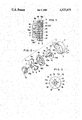
- FIG. 1 is a cross section illustrating a typical damper of this invention in an assembled state.
- FIG. 2 is a perspective view of the damper of FIG. 1 in a disassembled state.
- FIG. 3 is an explanatory diagram of a rotator showing the front view thereof in one half and the rear view thereof in the other half.
- 1 and 2 denote a base and a cap molded of a plastic material to form a cylindrical housing.
- the base 1 integrally comprises a cylindrical wall 3 having a bottom and fitting pieces 4 extended outwardly from the cylindrical wall 3 and adapted to be fastened to the machine with which the damper is to be used.
- the cap 2 comprises a covering wall 5 adapted to come into intimate contact with the open end face of the cylindrical wall 3, an engaging wall 6 extended inwardly in the axial direction from the inner side of the covering wall 5 for enough to come into engagement with the inner wall of the cylindrical wall 3 to substantially one half the length of the inner wall in the axial direction, and a boss 7 projecting outwardly in the axial direction from the center of the outer side of the covering wall.
- a continuous central hole 8 extends through the covering wall 5 and the boss 7.
- annular ridge 9a and an annular groove 9b together constituting a snap engaging means 9 adapted to come into snapping engagement when the engaging wall 6 is forced into the cylindrical wall along the inner wall thereof and the covering wall 5 is consequently allowed to close the open side of the cylindrical wall.
- the rotator 10 comprises a braking disk 11 and a hollow shaft 12 projected from the central part of one side of the braking disk 11.
- This hollow shaft 12 passes through the central hole 8 of the cap outwardly from the inner side of the cap 2 and projects beyond the leading end of the boss 7.
- the diameter of the braking disk 11 is slightly smaller than the inside diameter of the engaging wall 6.
- the braking disk 11 is provided around the base of the hollow shaft 12 with one or a plurality of window holes 14 (four window holes spaced equally in the circumferential direction in the illustrated embodiment). It is further provided on the surface 11b opposite from the surface 11a supporting the hollow shaft 12 with a plurality of circumferentially distributed protuberances 15 adapted to collide against the bottom surface of the cylindrical wall 3 and retain gaps on the bottom surface. These gaps serve to enable the oil which is injected through the hollow part as described afterward to flow into the housing from the inner edge of the hollow shaft 12.
- Denoted by 16 is a soft flexible membrane possessing elasticity.
- This flexible membrane readily deforms under the pressure exerted by the oil when the oil is thermally expanded, so as to absorb any voluminal change of the oil.
- This flexible membrane is molded as a thin wall with a material having a small coefficient of thermal expansion such as, for example, a synthetic rubber or a flexible plastic, typically polyethylene or polypropylene. It is provided on the inner wall thereof with an annular lip 16a adapted to come into sealing contact with the outer wall of the hollow shaft 12 and prevent the oil from flowing along the outer surface of the hollow shaft 12 and leaking out of the housing. It is further provided on the outer wall thereof with an annular ridge 16b and an external edge 16c.
- the outside diameter of the flexible membrane is larger than the inside diameter of the cylindrical wall 3.
- the flexible membrane is secured to the housing by bringing the outer edge 16c into engagement with the annular groove 9b on the inner wall of the cylindrical wall 3 and setting the cap 2 into snapping engagement with the annular groove.
- the flexible membrane nevertheless is allowed to keep a distance from the surface 11a of the braking disk 11.
- the toothed wheel 13 is provided in advance with a pin 13a adapted to be forced into the hollow part 12' of the shaft 12.
- Assembly of the damper is accomplished by fitting the inner wall of the flexible membrane 16 around the hollow shaft 12, then passing the hollow shaft through the central hole 8 of the cap 2 outwardly from the inner side of the cap until the tip of the shaft projects out of the leading end of the boss 7, setting the braking disk 11 and the flexible membrane 16 in place inside the cylindrical wall of the base, and forcing the cap into the cylindrical wall along the inner wall thereof. Consequently, the cap 2 is fastened to the base 1 by the snap engaging means 9 to give rise to a housing and, at the same time, the outer edge 16c of the flexible membrane 16 is engaged with the annular groove 9b. At this time, the annular ridge 16b of the flexible membrane 16 collides with the bottom surface of the covering wall 5 of the cap 2 to stabilize the shape of the flexible membrane 16 in its fixed condition.
- oil is injected through the outer extremity of the hollow part 12' of the shaft 12 by the use of an oiler of the shape of a syringe.
- the oil flows into and fills up the gaps formed by the protuberances 15 between the surface 11b of the braking disk and the bottom of the cylindrical wall 3.
- the oil also flows on the outer wall of the braking disk and through the window holes 14 to reach the other surface 11a and fill up the gap between the flexible membrane 16 and the surface 11a.
- the oil filled region is denoted by 17 in FIG. 1.
- the outer extremity 12a of the shaft 12 is given a generally elliptical profile, and the toothed wheel is provided around the base of the pin 13a with a similarly shaped depression.
- the shapes of the profile, the depression, and the cross sections are not limited to ellipses. They may instead be semicircular (like the letter D) or polygonal.
- the pin 13a of the toothed wheel 13 is inserted into the hollow part 12' of the shaft 12 from the outer side to perfectly close the hollow part.
- air remaining in the hollow part 12' escapes through a gap between the pin 13 and the inner periphery of the shaft 12 as the pin 13 is inserted into the hollow part 12'.
- the oil thus introduced into the housing is tightly closed in because the outer edge 16c of the flexible membrane 16 is pressed on and engaged with the annular groove 9b of the housing by the annular ridge 9a of the cap 2 and the outer side surface and outer peripheral surface of the shafts 12 come into tight contact with the peripheral surface of the depression formed around the base of the pin 13a.
- the outer boundary of the flexible membrane 16 is sealed and, in the meantime, the annular lip 16a on the inner wall of the flexible membrane is tightly fitted around the hollow shaft 12 of the rotator 10.
- the oil can be supplied to the surface 11a side of the disk through the window holes 14 as well as around the outer boundary of the disk. Consequently, the time required for the injection of the oil can be shortened and the damper's braking effect can be improved.
- the braking disk 11 is provided concentrically therein with empty parts 11' arranged in a cruciform pattern and it is further provided concentrically on the surface 11a with a thin-walled disk part 18 adapted to cover the region of the empty parts 11' near the center of the braking disk 11.
- the edges of the empty parts 11' which are not closed by the thin-walled disk part 18 serve as window holes 14.
- the protuberances 15 are formed at the four corners distributed in a cruciform pattern on the surface 11b.
- the hollow shaft 12 extends through the thin-walled disk part 18 and the inner extremity of the hollow part 12' opens into the thin-walled disk part 18.
- the injected oil is made to flow from the inner end of the shaft into the empty parts 11' distributed in a cruciform pattern, then led through the empty parts in the direction of the window holes 14.
- Part of the oil flows through the window holes 14 and fills up the gap on the surface 11a side of the braking disk and the remaining part of the oil fills up the gaps formed by the protuberances 15.
- the present invention obviates the need to spend much time and labor for the application of the oil to the braking disk using a brush, for example.
- injection of the proper amount of oil can be obtained by using an oiler capable of injecting a fixed amount of oil each time.
- a typical example of such an oiler is a transparent graduated cylinder which, like a syringe, shows the supply of oil held inside.
- the illustrated embodiment has one rotator provided within one housing.
- a partition wall may be formed inside the housing, tubular walls may be extended outwardly from the opposite sides of the partition wall, and two rotators may be fitted in mutually opposite directions into the tubular walls.
Abstract
Description
Claims (2)
Priority Applications (1)
| Application Number | Priority Date | Filing Date | Title |
|---|---|---|---|
| US06/601,899 US4527675A (en) | 1984-04-19 | 1984-04-19 | Oil type damper |
Applications Claiming Priority (1)
| Application Number | Priority Date | Filing Date | Title |
|---|---|---|---|
| US06/601,899 US4527675A (en) | 1984-04-19 | 1984-04-19 | Oil type damper |
Publications (1)
| Publication Number | Publication Date |
|---|---|
| US4527675A true US4527675A (en) | 1985-07-09 |
Family
ID=24409194
Family Applications (1)
| Application Number | Title | Priority Date | Filing Date |
|---|---|---|---|
| US06/601,899 Expired - Fee Related US4527675A (en) | 1984-04-19 | 1984-04-19 | Oil type damper |
Country Status (1)
| Country | Link |
|---|---|
| US (1) | US4527675A (en) |
Cited By (35)
| Publication number | Priority date | Publication date | Assignee | Title |
|---|---|---|---|---|
| WO1987001620A1 (en) * | 1985-09-18 | 1987-03-26 | Nelson Irrigation Corporation | Rotary sprinkler head |
| US4653616A (en) * | 1984-09-07 | 1987-03-31 | Nifco, Inc. | Damper |
| US4694530A (en) * | 1985-04-24 | 1987-09-22 | Foggini Progetti S.R.L. | Device for controlling opening and closing of movable objects, in particular doors and drawers in motor vehicles, having mutually cooperating stator and rotor |
| US4697673A (en) * | 1984-07-16 | 1987-10-06 | Nifco Inc. | One-way damper |
| US4741227A (en) * | 1986-06-19 | 1988-05-03 | 501 Kubota, Ltd. | Tractor transmission to permit smooth change of speed operation effectuated by rotational resistance |
| US4768630A (en) * | 1985-12-30 | 1988-09-06 | Aerospatiale Societe Nationale Industrielle | Rotary damper |
| US4773242A (en) * | 1988-02-17 | 1988-09-27 | General Motors Corporation | Lock cylinder cover with time delay closure |
| US4825983A (en) * | 1987-03-14 | 1989-05-02 | Motoyasu Nakanishi | Inertia damper |
| US4869125A (en) * | 1987-10-08 | 1989-09-26 | Nifco Inc. | Rotary oil damper |
| US4908905A (en) * | 1988-01-12 | 1990-03-20 | Nifco, Inc. | Rotary damper |
| USRE33823E (en) * | 1985-09-18 | 1992-02-18 | Nelson Irrigation Corporation | Rotary sprinkler head |
| US5211267A (en) * | 1992-02-24 | 1993-05-18 | Prince Corporation | Temperature compensated rotary damper |
| US5269397A (en) * | 1991-03-11 | 1993-12-14 | Nifco Inc. | Rotary damper with improved connection between cap and housing |
| US5301775A (en) * | 1993-06-29 | 1994-04-12 | Illinois Tool Works Inc. | Adjustable high torque damper device |
| US5355979A (en) * | 1991-10-25 | 1994-10-18 | Stephan Christoph H | Damping element for damping translatory motion |
| DE4338163A1 (en) * | 1993-11-09 | 1995-05-11 | Behr Gmbh & Co | Fluid friction coupling with means of securing against rotation |
| US5460252A (en) * | 1994-02-23 | 1995-10-24 | Illinois Tool Works Inc. | One-way rotary damper |
| US5718309A (en) * | 1995-09-01 | 1998-02-17 | Nifco Inc. | Rotary damper with grooves and wall spaces |
| US6298960B1 (en) * | 2000-05-30 | 2001-10-09 | Illinois Tool Works Inc. | Small viscous precision damper |
| US6530532B1 (en) | 2000-02-05 | 2003-03-11 | Senninger Irrigation, Inc. | Kick-starter for sprinkler heads |
| US6678918B2 (en) * | 2001-04-25 | 2004-01-20 | Piolax Inc. | Open-close apparatus |
| US20040226789A1 (en) * | 2003-04-15 | 2004-11-18 | Doornbos David A. | Damper |
| US20060011428A1 (en) * | 2004-07-14 | 2006-01-19 | Nifco Inc. | Rotary damper |
| US20060042301A1 (en) * | 2004-08-26 | 2006-03-02 | Lg Electronics Inc. | Refrigerator having basket lift apparatus |
| US20060207844A1 (en) * | 2003-09-17 | 2006-09-21 | Nifco Inc. | Rotating damper |
| WO2007099508A2 (en) * | 2006-03-03 | 2007-09-07 | Antonino Cultraro | A device for braking the movement of a door, drawer or similar movable member |
| US20070256847A1 (en) * | 2006-05-02 | 2007-11-08 | Mohsein Wan | Hand power tool |
| CN100398867C (en) * | 2004-07-14 | 2008-07-02 | 株式会社利富高 | Rotary damper |
| US20080284193A1 (en) * | 2007-05-16 | 2008-11-20 | Z F Group North American Operations, Inc. | Tailgate dampener |
| US20090277735A1 (en) * | 2006-10-31 | 2009-11-12 | Keiji Yamaguchi | Rotation damper |
| CN101466963B (en) * | 2006-03-29 | 2011-05-25 | 株式会社利富高 | Rotary damper |
| US20110296938A1 (en) * | 2009-02-23 | 2011-12-08 | Illinois Tool Works Inc. | Damper assembly and device utilizing the same |
| JP2013007414A (en) * | 2011-06-23 | 2013-01-10 | Nifco Inc | Rotary damper |
| DE102014107347A1 (en) * | 2014-05-26 | 2015-11-26 | Weber Gmbh & Co. Kg Kunststofftechnik Und Formenbau | With a damping medium filled rotary damper and method for filling it |
| CN106255616A (en) * | 2014-05-08 | 2016-12-21 | 现代岱摩斯 | Electric headrest |
Citations (3)
| Publication number | Priority date | Publication date | Assignee | Title |
|---|---|---|---|---|
| US3861503A (en) * | 1972-01-21 | 1975-01-21 | Nash Alan R B | Dampers |
| JPS5575805A (en) * | 1978-12-05 | 1980-06-07 | Kawasaki Steel Corp | Skew rolling method for plate |
| US4342135A (en) * | 1979-10-03 | 1982-08-03 | Sharp Corporation | Device for moderating movement of lid |
-
1984
- 1984-04-19 US US06/601,899 patent/US4527675A/en not_active Expired - Fee Related
Patent Citations (3)
| Publication number | Priority date | Publication date | Assignee | Title |
|---|---|---|---|---|
| US3861503A (en) * | 1972-01-21 | 1975-01-21 | Nash Alan R B | Dampers |
| JPS5575805A (en) * | 1978-12-05 | 1980-06-07 | Kawasaki Steel Corp | Skew rolling method for plate |
| US4342135A (en) * | 1979-10-03 | 1982-08-03 | Sharp Corporation | Device for moderating movement of lid |
Cited By (48)
| Publication number | Priority date | Publication date | Assignee | Title |
|---|---|---|---|---|
| US4697673A (en) * | 1984-07-16 | 1987-10-06 | Nifco Inc. | One-way damper |
| US4653616A (en) * | 1984-09-07 | 1987-03-31 | Nifco, Inc. | Damper |
| US4694530A (en) * | 1985-04-24 | 1987-09-22 | Foggini Progetti S.R.L. | Device for controlling opening and closing of movable objects, in particular doors and drawers in motor vehicles, having mutually cooperating stator and rotor |
| WO1987001620A1 (en) * | 1985-09-18 | 1987-03-26 | Nelson Irrigation Corporation | Rotary sprinkler head |
| US4660766A (en) * | 1985-09-18 | 1987-04-28 | Nelson Irrigation Corporation | Rotary sprinkler head |
| USRE33823E (en) * | 1985-09-18 | 1992-02-18 | Nelson Irrigation Corporation | Rotary sprinkler head |
| US4768630A (en) * | 1985-12-30 | 1988-09-06 | Aerospatiale Societe Nationale Industrielle | Rotary damper |
| US4741227A (en) * | 1986-06-19 | 1988-05-03 | 501 Kubota, Ltd. | Tractor transmission to permit smooth change of speed operation effectuated by rotational resistance |
| US4825983A (en) * | 1987-03-14 | 1989-05-02 | Motoyasu Nakanishi | Inertia damper |
| US4869125A (en) * | 1987-10-08 | 1989-09-26 | Nifco Inc. | Rotary oil damper |
| US4908905A (en) * | 1988-01-12 | 1990-03-20 | Nifco, Inc. | Rotary damper |
| US4773242A (en) * | 1988-02-17 | 1988-09-27 | General Motors Corporation | Lock cylinder cover with time delay closure |
| US5269397A (en) * | 1991-03-11 | 1993-12-14 | Nifco Inc. | Rotary damper with improved connection between cap and housing |
| US5355979A (en) * | 1991-10-25 | 1994-10-18 | Stephan Christoph H | Damping element for damping translatory motion |
| US5211267A (en) * | 1992-02-24 | 1993-05-18 | Prince Corporation | Temperature compensated rotary damper |
| US5301775A (en) * | 1993-06-29 | 1994-04-12 | Illinois Tool Works Inc. | Adjustable high torque damper device |
| DE4338163A1 (en) * | 1993-11-09 | 1995-05-11 | Behr Gmbh & Co | Fluid friction coupling with means of securing against rotation |
| US5601170A (en) * | 1993-11-09 | 1997-02-11 | Behr Gmbh & Co. | Fluid friction coupling |
| US5460252A (en) * | 1994-02-23 | 1995-10-24 | Illinois Tool Works Inc. | One-way rotary damper |
| US5718309A (en) * | 1995-09-01 | 1998-02-17 | Nifco Inc. | Rotary damper with grooves and wall spaces |
| US6530532B1 (en) | 2000-02-05 | 2003-03-11 | Senninger Irrigation, Inc. | Kick-starter for sprinkler heads |
| US6298960B1 (en) * | 2000-05-30 | 2001-10-09 | Illinois Tool Works Inc. | Small viscous precision damper |
| US6678918B2 (en) * | 2001-04-25 | 2004-01-20 | Piolax Inc. | Open-close apparatus |
| US6968929B2 (en) | 2003-04-15 | 2005-11-29 | Illinois Tool Works Inc. | Damper |
| US20040226789A1 (en) * | 2003-04-15 | 2004-11-18 | Doornbos David A. | Damper |
| US20060207844A1 (en) * | 2003-09-17 | 2006-09-21 | Nifco Inc. | Rotating damper |
| US7938238B2 (en) * | 2003-09-17 | 2011-05-10 | Nifco Inc. | Rotary damper |
| US7264096B2 (en) * | 2004-07-14 | 2007-09-04 | Nifco Inc. | Rotary damper |
| US20060011428A1 (en) * | 2004-07-14 | 2006-01-19 | Nifco Inc. | Rotary damper |
| CN100398867C (en) * | 2004-07-14 | 2008-07-02 | 株式会社利富高 | Rotary damper |
| US20060042301A1 (en) * | 2004-08-26 | 2006-03-02 | Lg Electronics Inc. | Refrigerator having basket lift apparatus |
| US7600829B2 (en) * | 2004-08-26 | 2009-10-13 | Lg Electronics Inc. | Refrigerator having basket lift apparatus |
| WO2007099508A2 (en) * | 2006-03-03 | 2007-09-07 | Antonino Cultraro | A device for braking the movement of a door, drawer or similar movable member |
| WO2007099508A3 (en) * | 2006-03-03 | 2007-12-13 | Antonino Cultraro | A device for braking the movement of a door, drawer or similar movable member |
| US20090064455A1 (en) * | 2006-03-03 | 2009-03-12 | Antonino Cultraro | Device for braking the movement of a door, drawer or similar movable member |
| US8042660B2 (en) | 2006-03-03 | 2011-10-25 | Antonino Cultraro | Device for braking the movement of a door, drawer or similar movable member |
| CN101846151B (en) * | 2006-03-29 | 2012-07-18 | 株式会社利富高 | Rotary damper |
| CN101466963B (en) * | 2006-03-29 | 2011-05-25 | 株式会社利富高 | Rotary damper |
| US20070256847A1 (en) * | 2006-05-02 | 2007-11-08 | Mohsein Wan | Hand power tool |
| US7845427B2 (en) * | 2006-05-02 | 2010-12-07 | Robert Bosch Gmbh | Sealing element of hand power tool housing |
| US20090277735A1 (en) * | 2006-10-31 | 2009-11-12 | Keiji Yamaguchi | Rotation damper |
| US20080284193A1 (en) * | 2007-05-16 | 2008-11-20 | Z F Group North American Operations, Inc. | Tailgate dampener |
| US20110296938A1 (en) * | 2009-02-23 | 2011-12-08 | Illinois Tool Works Inc. | Damper assembly and device utilizing the same |
| JP2012518759A (en) * | 2009-02-23 | 2012-08-16 | イリノイ トゥール ワークス インコーポレイティド | Damper assembly and apparatus using the assembly |
| US9261158B2 (en) * | 2009-02-23 | 2016-02-16 | Illinois Tool Works Inc. | Damper assembly and device utilizing the same |
| JP2013007414A (en) * | 2011-06-23 | 2013-01-10 | Nifco Inc | Rotary damper |
| CN106255616A (en) * | 2014-05-08 | 2016-12-21 | 现代岱摩斯 | Electric headrest |
| DE102014107347A1 (en) * | 2014-05-26 | 2015-11-26 | Weber Gmbh & Co. Kg Kunststofftechnik Und Formenbau | With a damping medium filled rotary damper and method for filling it |
Similar Documents
| Publication | Publication Date | Title |
|---|---|---|
| US4527675A (en) | Oil type damper | |
| US4614004A (en) | Oil filled rotary damper having a symmetrically shaped flexible membrane | |
| US4638528A (en) | Oil type damper | |
| US4571773A (en) | Damper for braking rotation | |
| US5868287A (en) | Liquid dispensing container using pressure of liquid to open disharge opening | |
| US7264096B2 (en) | Rotary damper | |
| JP3415560B2 (en) | Equipment for storage and application of substances, especially cosmetics | |
| JP4746626B2 (en) | Mascara application and packaging device and its use for cosmetics | |
| US5568990A (en) | Shoe polish applicator | |
| US4513473A (en) | Sealed rotary motion damper | |
| JP2005261934A (en) | Iron club head | |
| US6688793B2 (en) | Applicator device for applying product | |
| JP2002034648A (en) | Applicator device and its case having applicator region to be preferentially supplied | |
| WO2008053574A1 (en) | Rotation damper | |
| US4565266A (en) | Oil type damper | |
| US7575108B2 (en) | Damper | |
| US4653616A (en) | Damper | |
| KR101857802B1 (en) | Applicator airtight sealed structure for gel type makeup pencil | |
| JPH0210350Y2 (en) | ||
| JPS6137878Y2 (en) | ||
| US5294206A (en) | Liquid application with resilient support | |
| JPH0235071Y2 (en) | ||
| JPH09188349A (en) | Discharging container | |
| JPS6238932Y2 (en) | ||
| JPH0238653Y2 (en) |
Legal Events
| Date | Code | Title | Description |
|---|---|---|---|
| AS | Assignment |
Owner name: NIFCO INC., 184-1, MAIOKA-CHO, TOTSUKA-KU, YOKOHAM Free format text: ASSIGNMENT OF ASSIGNORS INTEREST.;ASSIGNORS:OMATA, NOBUAKI;OSHIDA, TSUTOMU;REEL/FRAME:004252/0328 Effective date: 19840409 |
|
| FEPP | Fee payment procedure |
Free format text: PAYOR NUMBER ASSIGNED (ORIGINAL EVENT CODE: ASPN); ENTITY STATUS OF PATENT OWNER: LARGE ENTITY |
|
| FPAY | Fee payment |
Year of fee payment: 4 |
|
| FPAY | Fee payment |
Year of fee payment: 8 |
|
| REMI | Maintenance fee reminder mailed | ||
| LAPS | Lapse for failure to pay maintenance fees | ||
| FP | Lapsed due to failure to pay maintenance fee |
Effective date: 19970709 |
|
| STCH | Information on status: patent discontinuation |
Free format text: PATENT EXPIRED DUE TO NONPAYMENT OF MAINTENANCE FEES UNDER 37 CFR 1.362 |