US4537255A - Back-off tool - Google Patents
Back-off tool Download PDFInfo
- Publication number
- US4537255A US4537255A US06/506,739 US50673983A US4537255A US 4537255 A US4537255 A US 4537255A US 50673983 A US50673983 A US 50673983A US 4537255 A US4537255 A US 4537255A
- Authority
- US
- United States
- Prior art keywords
- tool
- explosive
- housing
- pellets
- tubular housing
- Prior art date
- Legal status (The legal status is an assumption and is not a legal conclusion. Google has not performed a legal analysis and makes no representation as to the accuracy of the status listed.)
- Expired - Fee Related
Links
Images

Classifications
-
- E—FIXED CONSTRUCTIONS
- E21—EARTH DRILLING; MINING
- E21B—EARTH DRILLING, e.g. DEEP DRILLING; OBTAINING OIL, GAS, WATER, SOLUBLE OR MELTABLE MATERIALS OR A SLURRY OF MINERALS FROM WELLS
- E21B31/00—Fishing for or freeing objects in boreholes or wells
- E21B31/107—Fishing for or freeing objects in boreholes or wells using impact means for releasing stuck parts, e.g. jars
- E21B31/1075—Fishing for or freeing objects in boreholes or wells using impact means for releasing stuck parts, e.g. jars using explosives
Definitions
- the present invention relates to a back-off tool adapted to be lowered into a pipe string in a well bore to apply an explosive shock at a threaded coupling between pipes in the pipe string so as to jar the coupling so that torque applied to the pipe string at the surface will "back off” the threads at that coupling to uncouple the string at that location.
- the usual prior art device employed to accomplish this result comprises lengths of detonating cord taped to a central steel rod which is lowered by wireline into the pipe string, then electrically detonated at the desired location.
- This prior art method known as a "string shot”
- cord shot leaves tape debris in the well and requires side detonation from cord to cord, which not only is somewhat unreliable, but produces a ragged, non-uniform explosion which may or may not produce a shock wave of the necessary magnitude and uniformity.
- the detonating cord used in the prior art device must be shipped at a high cost due to explosive shipping regulations, because of the amount of explosive in a length of the cord.
- U.S. Pat. No. 2,911,909 discloses a droppable back-off tool which is actuated by the impact of the tool on a sub previously placed at a particular location downhole. This has the disadvantage of not being able to effect the explosion where desired, as well as restricting the bore of the pipe. In addition, there is no assurance that the tool impact will be great enough to actuate the detonator. Moreover, the tool employs detonating cord which must be somehow maintained in a groove on the tool exterior, the means for such maintenance not being disclosed.
- U.S. Pat. No. 4,007,790 discloses a back-off apparatus which relies upon a non-destructive explosive to provide a jarring force to a pipe coupling through mechanical jarring means.
- the nature or configuration of the explosive is not disclosed.
- the explosive force which may be applied to the pipe coupling is limited by the reusable nature of the apparatus.
- U.S. Pat. No. 3,174,545 discloses a device employed in a method of explosive-induced hydraulic fracturing, which device includes an explosive contained in a frangible housing, which explosive is detonated by electrically actuated detonating means.
- the device as disclosed produces an irregular, pulsating explosion or series of explosions to generate fluid pressure pulsations, and fragments of the destroyed housing are designed to plug some of the perforations in the well bore casing so that the hydraulic force will act more strongly against others.
- This device is obviously unsuitable for use as a back-off tool due to the design of the explosive charge as well as the relatively large nature of the housing fragments produced as a result of the explosive detonation, which fragments could inhibit subequent drilling, well treatment and production.
- the present invention comprises a back-off tool having a tubular housing reducible to fine particles upon detonation of the explosive contained within, which explosive may be in the form of pellets so as to easily vary the amount of explosive force generated.
- One preferred embodiment employs a pressure-tight housing for the explosive; a second preferred embodiment utilizes well bore pressure to act upon the explosive, substantially balancing interior and exterior housing pressures so as to permit a thinner housing.
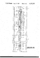
- FIGS. 1A and 1B are a full vertical section of a first preferred embodiment of the back-off tool of the present invention shown in position adjacent a threaded coupling in a pipe string.
- FIG. 2 is a drawing similar to FIGS. 1A and 1B showing a second preferred embodiment of the back-off tool of the present invention.
- FIGS. 1A and 1B illustrate a first preferred embodiment of the present invention.
- Back-off tool 10 is shown suspended in a pipe string 6 adjacent threaded coupling 8.
- Extension mandrel 12 which is preferably formed of steel, is threaded at 14 to steel firing head mandrel 16.
- Electrical wireline 4 extends upward to the top of extension mandrel 12, where it is secured thereto (not shown), subsequently extending to the drilling rig at the surface.
- firing head mandrel 16 has a substantially cylindrical upper exterior surface 18 which terminates at annular shoulder 20, below which a lower cylindrical exterior surface 22 extends to the bottom of firing head mandrel 16, O-ring 29 forming a fluid-tight seal therebetween.
- Tubular sleeve 40 surrounds the upper exterior of housing 30, and has a cylindrical exterior surface 42 which terminates in threads 44 at its upper end, which does not quite extend to the top of housing 30.
- Housing 30 and sleeve 40 are preferably formed of a non-metallic filamentary or fiber-reinforced composite material which is reducible to fine particulate matter when subjected to an explosive force.
- Such materials include, but are not limited to, graphite reinforced epoxy or glass reinforced epoxy, which materials are commercially available from Hercules, Inc., Skyline Industries and numerous other manufacturers. The selected material must possess sufficient strength so as not to rupture or distort (thereby causing leakage) under well bore pressures, which could affect the detonation or performance of the back-off charge.
- Housing 30 and sleeve 40 may be epoxy bonded together at area 46, or throughout the length of their contact.
- Connector 50 rides upon upper cylindrical surface of firing head mandrel 16, through the contact of radially inward extending annular shoulder 52 therewith. Below annular shoulder, inner bore 54 is threaded at its lower extent 56 to mate with threads 44 on sleeve 40. When threads 44 and 56 are made up, connector 50 maintains housing 30 tightly against annular shoulder 20 on firing head mandrel 16.
- Plug 60 preferably of a similar material to housing 30, is inserted in the lower bore 34 of housing 30, and is secured thereto by steel pin 62, which extends through radial bore 64 in plug 60 and radial apertures 66 and 68 at the lower end of housing 30.
- plug 60 is also preferably of a filamentary composite material, and is epoxy bonded about its periphery to housing 30 to ensure a fluid and pressure-tight seal, plug 60, housing 30 and firing head mandrel 26 forming a pressure-tight vessel.
- tube 70 which may comprise paper, contains a plurality of explosive pellets 72.
- the grain loading (mass of explosive per foot of length) of the pellets may be easily varied by varying the pellet diameter and employing tubes 70 of greater or lesser wall thickness to ensure a snug fit of the explosive pellets therein.
- Pellets 72 may comprise any of a number of suitable explosive compounds, including but not limited to: cyclotrimethylenetrinitramine, hexahydro-1,3,5-trinitro-5-triazine, cyclonite, hexogen, T4, commonly referred to as RDX; octogen, known as HMX; 2,2',4,4',6,6'-hexanitrostilbene, known as HNS; or 2,6-bis(Picrylamino)-3,5,dinitropyridine, known as PYX.
- suitable explosive compounds including but not limited to: cyclotrimethylenetrinitramine, hexahydro-1,3,5-trinitro-5-triazine, cyclonite, hexogen, T4, commonly referred to as RDX; octogen, known as HMX; 2,2',4,4',6,6'-hexanitrostilbene, known as HNS; or 2,6-bis(Picrylamino)-3,5,
- the explosive can be grouped in packets of no more than 22.7 grams total weight each, so as to enable their shipment as class "C” explosives.
- the ability to ship the pellets as class "C” explosives greatly facilitates their transportability on commercial carriers, and therefore reduces the time, money and effort spent to transport the back-off tool to the site of usage.
- the desired number of pellets may then be inserted into tube 70 and tube 70 inserted into housing 30 prior to the insertion of firing head mandrel 16 into upper housing bore 38.
- booster charge 80 is inserted into housing 30 at the end of firing head mandrel 16.
- the upper portion 82 of booster charge 80 rides in lower mandrel bore 24, and the bottom end 84 of booster charge 80 is biased against the top pellet 72 by coil spring 90 which extends from firing connector head 100 to booster charge 80.
- Ignition wire 102 extends from booster charge 80 through the center of spring 90 to firing connector 104.
- Firing connector head 100 has annular groove around its periphery by which O-ring 108 maintains a fluid-tight seal against upper bore 28.
- Firing connector 104 is electrically insulated from the outer shell of firing connector head 100 and firing head mandrel 16. Ground wire 106 winds around the periphery of coil spring 90 from booster charge 80 and grounds out on firing head mandrel 16 through firing connector head 100.
- FIG. 2 of the drawings shows a second preferred embodiment of the back-off tool of the present invention.
- Back-off tool 200 is suspended in pipe string 6 adjacent threaded coupling 8.
- Extension mandrel 12 is threaded to firing head mandrel 216 at 214.
- electrical wireline 4 extends upward to the top of extension mandrel 12 where it is secured thereto (not shown), subsequently extending to the drilling rig at the surface.
- firing head mandrel 216 comprises on its exterior cylindrical surface 218, radially outward extending annular shoulder 220, threaded cylindrical surface 222, oblique annular wall 224, and lower cylindrical surface 226 in which O-ring 228 is held in an annular groove (unnumbered).
- the bottom 230 of firing head mandrel is radially flat.
- Tubular housing 240 is preferably formed of the same materials as housing 30 of the first preferred embodiment of FIGS. 1A and 1B. Furthermore, housing 240 has a much thinner wall than housing 30, the mechanism by which a thinner wall is made practical being explained hereafter. Housing 240 possesses an exterior surface having an annular surface 242 at its lower extent, followed by lower cylindrical surface 244, which steps at 246 to upper cylindrical surface 248, which terminated in flared end 250. The lower end of housing 240 has axial aperture 252 therethrough, opening into pressure compensation chamber 258, radially defined by lower bore 254, which extends upward to upper bore 256, terminating at flared end 250.
- Tubular shell nut 320 having threaded bore 322 therein terminating at obliqued annular shoulder 324, which leads radially inwardly to lower smooth bore 326.
- Shell nut 320 secures firing head mandrel 216 and housing 240 together when threads 222 and 322 are made up.
- Tubular pressure compensation plug 260 is preferably of the same material as housing 240, with the same or lesser wall thickness. At its upper end, plug 260 has collar 262 of slightly lesser exterior diameter than the diameter of bore 256, O-ring seal 264 forming a substantially fluid and pressure-tight sliding seal between collar 262 and housing 240. Lower end 266 of plug 260 is closed. Plug 260 contains a plurality of explosive pellets 270, which may be formed of the same explosive compounds noted with respect to pellets 72 in FIGS. 1A and 1B.
- U.S. Pat. No. 3,174,545 previously described herein with respect to the background of the present invention, discloses the use of a pressure compensation piston or plug. However, the configuration of the plug disclosed therein and the characteristics of the explosive employed render it unsuitable for use in a back-off tool as that plug would either remain undestroyed after explosion of the explosive material or comprise very large fragments.
- larger explosive pellets 272 in housing 240 may be of those same explosive compounds.
- the same advantages of pelletized explosives previously enumerated with respect to back-off tool 10 are equally applicable to back-off tool 200.
- the explosive pellets may be placed within a paper tube prior to insertion in housing 240 for convenience and ease of handling, including easy variation of grain loading for the same diameter housing.
- Flat lower end 230 of firing head mandrel has barrier wall 280 therebehind, above which standoff chamber 282 defined by lower bore wall 284 is located. Above standoff chamber 282, booster charge chamber 286 is defined by intermediate bore wall 288 of larger diameter than bore wall 284. Stepped bore walls 290 and 292 above intermediate bore wall 288 lead to the top of firing head mandrel 216.
- Booster assembly 300 comprises booster charge 302, similar to booster charge 80. However, in addition to booster charge 302, booster assembly 300 additionally employs shaped charge booster 304 at its lower end. Booster assembly 300 is placed into firing head mandrel 216, but does not go to the bottom thereof due to the small diameter of lower bore wall 284, which thereby assures proper standoff for shaped charge booster 304. Booster assembly 300 is connected to firing head connector 332 of firing head 330 by ignition wire 334, which runs through the center of coil spring 336. Firing head connector 332 is electrically insulated from the shell of firing head 330 and firing head mandrel 216. Ground wire 338 is wound about spring 336, and grounded on firing head mandrel 216 through the exterior shell of firing head 330. O-ring 340 effects a fluid and pressure-tight seal between firing head 330 and firing head mandrel 216, booster assembly 300 thereby being contained within a pressure-tight vessel.
- Back-off tools 10 and 240 operate in substantially the same manner. Both are preferably transported to the well site without booster charges or pelletized explosives. The desired size pellets for proper grain loading are selected, and if necessary for proper fit, placed in a paper tube prior to insertion in the back-off tool housing.
- a common grain loading which may be employed in tools 10 and 200 is 600 grains/foot of HMX explosive.
- booster charge 80 is placed in firing head mandrel 16 with spring 90 thereabove, and wires 102 and 106 connected to firing head 100. Firing head mandrel 16 is then inserted into housing 30, and firing head 100 inserted securely into firing head mandrel 16, which assures proper biasing of booster charge 82 against top pellet 72 by spring 90, charge 80 being centered due to the extension of upper portion 82 into firing head mandrel 16.
- Connector 50 is made up on sleeve 40, holding firing head mandrel 16 in place, shoulder 20 being held between connector 50 and housing 30.
- Extension mandrel 12 is then made up with firing head mandrel 16 and back-off tool 10 lowered to its location across threaded coupling 8. It should be noted that pellets 72 and booster charge 80 are within a pressure-tight vessel, isolated from well bore fluid and pressure to ensure proper detonation.
- Back-off tool 200 is assembled in a slightly different manner.
- Pressure compensation plug 260 will be filled with pellets 270 to assure its destruction, and plug 260 inserted into housing 240 from the top end.
- Pellets 272 are then inserted into housing 240 above plug 260, inside a paper tube if necessary for proper grain loading.
- Firing head mandrel 216 is then loaded with booster assembly 300, connected to firing head 330 by wires 334 and 338, with spring 336 therebetween.
- Firing head mandrel 216 is inserted into housing 240, and shell nut 320 made up to secure the two pieces together.
- Firing head 330 is then inserted securely into firing head mandrel 216, creating a pressure-tight vessel for booster assembly 300.
- Exterior mandrel 12 is made up, and back-off tool 200 is lowered to its position across coupling 8.
- pressure from the well bore is allowed to act upon the interior of housing 240 through pressure compensation plug 260, thereby preventing its collapse and the collapse of plug 260 even with their exceedingly thin walls.
Abstract
Description
Claims (15)
Priority Applications (1)
| Application Number | Priority Date | Filing Date | Title |
|---|---|---|---|
| US06/506,739 US4537255A (en) | 1983-06-22 | 1983-06-22 | Back-off tool |
Applications Claiming Priority (1)
| Application Number | Priority Date | Filing Date | Title |
|---|---|---|---|
| US06/506,739 US4537255A (en) | 1983-06-22 | 1983-06-22 | Back-off tool |
Publications (1)
| Publication Number | Publication Date |
|---|---|
| US4537255A true US4537255A (en) | 1985-08-27 |
Family
ID=24015827
Family Applications (1)
| Application Number | Title | Priority Date | Filing Date |
|---|---|---|---|
| US06/506,739 Expired - Fee Related US4537255A (en) | 1983-06-22 | 1983-06-22 | Back-off tool |
Country Status (1)
| Country | Link |
|---|---|
| US (1) | US4537255A (en) |
Cited By (36)
| Publication number | Priority date | Publication date | Assignee | Title |
|---|---|---|---|---|
| US4757863A (en) * | 1987-04-24 | 1988-07-19 | Challacombe Robert D | Well cleaning method and apparatus |
| US4798244A (en) * | 1987-07-16 | 1989-01-17 | Trost Stephen A | Tool and process for stimulating a subterranean formation |
| US5238063A (en) * | 1992-08-04 | 1993-08-24 | Masx Energy Services Group, Inc. | Pressure balanced charge container for wellhead severing system |
| US5598891A (en) * | 1994-08-04 | 1997-02-04 | Marathon Oil Company | Apparatus and method for perforating and fracturing |
| US5720344A (en) * | 1996-10-21 | 1998-02-24 | Newman; Frederic M. | Method of longitudinally splitting a pipe coupling within a wellbore |
| US5960894A (en) * | 1998-03-13 | 1999-10-05 | Primex Technologies, Inc. | Expendable tubing conveyed perforator |
| US6003597A (en) * | 1998-05-16 | 1999-12-21 | Newman; Frederic M. | Directional coupling sensor for ensuring complete perforation of a wellbore casing |
| GB2365468A (en) * | 2000-08-04 | 2002-02-20 | Schlumberger Holdings | Impermeable and composite perforating gun assembly components |
| US6422148B1 (en) | 2000-08-04 | 2002-07-23 | Schlumberger Technology Corporation | Impermeable and composite perforating gun assembly components |
| US20040262004A1 (en) * | 2003-06-26 | 2004-12-30 | John Roberts | Method and apparatus for backing off a tubular member from a wellbore |
| US20050109509A1 (en) * | 2003-11-08 | 2005-05-26 | Snider Philip M. | Propellant ignition assembly and process |
| US20050211467A1 (en) * | 2004-03-24 | 2005-09-29 | Schlumberger Technology Corporation | Shaped Charge Loading Tube for Perforating Gun |
| US20050268776A1 (en) * | 2001-09-10 | 2005-12-08 | Titan Specialties, Ltd. | Explosive pipe severing tool |
| US20060185898A1 (en) * | 2005-02-23 | 2006-08-24 | Dale Seekford | Method and apparatus for stimulating wells with propellants |
| US20080011483A1 (en) * | 2006-05-26 | 2008-01-17 | Owen Oil Tools Lp | Perforating methods and devices for high wellbore pressure applications |
| US20100032151A1 (en) * | 2008-08-06 | 2010-02-11 | Duphorne Darin H | Convertible downhole devices |
| US20100212480A1 (en) * | 2001-09-10 | 2010-08-26 | Titan Specialties, Ltd. | Explosive well tool firing head |
| US8479808B2 (en) | 2011-06-01 | 2013-07-09 | Baker Hughes Incorporated | Downhole tools having radially expandable seat member |
| US8622141B2 (en) | 2011-08-16 | 2014-01-07 | Baker Hughes Incorporated | Degradable no-go component |
| US8668006B2 (en) | 2011-04-13 | 2014-03-11 | Baker Hughes Incorporated | Ball seat having ball support member |
| US8668018B2 (en) | 2011-03-10 | 2014-03-11 | Baker Hughes Incorporated | Selective dart system for actuating downhole tools and methods of using same |
| US8770301B2 (en) | 2001-09-10 | 2014-07-08 | William T. Bell | Explosive well tool firing head |
| US8851191B2 (en) | 2011-10-18 | 2014-10-07 | Baker Hughes Incorporated | Selectively fired high pressure high temperature back-off tool |
| US8939210B2 (en) | 2013-05-20 | 2015-01-27 | William T. Bell | Drill collar severing tool |
| US8967279B2 (en) | 2013-01-04 | 2015-03-03 | Baker Hughes Incorporated | Reinforced shear components and methods of using same |
| US9004091B2 (en) | 2011-12-08 | 2015-04-14 | Baker Hughes Incorporated | Shape-memory apparatuses for restricting fluid flow through a conduit and methods of using same |
| US9016388B2 (en) | 2012-02-03 | 2015-04-28 | Baker Hughes Incorporated | Wiper plug elements and methods of stimulating a wellbore environment |
| US9145758B2 (en) | 2011-06-09 | 2015-09-29 | Baker Hughes Incorporated | Sleeved ball seat |
| WO2016007160A1 (en) * | 2014-07-10 | 2016-01-14 | Halliburton Energy Services, Inc. | High temperature, high pressure back-off shot tool |
| WO2016010510A1 (en) * | 2014-07-14 | 2016-01-21 | Halliburton Energy Services, Inc. | Propellant back off tool |
| US9435170B2 (en) | 2013-05-20 | 2016-09-06 | William T. Bell | High energy severing tool with pressure balanced explosives |
| WO2017048290A1 (en) * | 2015-09-18 | 2017-03-23 | Bell William T | Mini-severing and back-off tool with pressure balanced explosives |
| WO2017048292A1 (en) * | 2015-09-18 | 2017-03-23 | Bell William T | String shot back-off tool with pressure-balanced explosives |
| US9677349B2 (en) | 2013-06-20 | 2017-06-13 | Baker Hughes Incorporated | Downhole entry guide having disappearing profile and methods of using same |
| US9689246B2 (en) | 2014-03-27 | 2017-06-27 | Orbital Atk, Inc. | Stimulation devices, initiation systems for stimulation devices and related methods |
| US11952872B2 (en) | 2013-07-18 | 2024-04-09 | DynaEnergetics Europe GmbH | Detonator positioning device |
Citations (14)
| Publication number | Priority date | Publication date | Assignee | Title |
|---|---|---|---|---|
| US2745345A (en) * | 1948-09-18 | 1956-05-15 | William G Sweetman | Apparatus for releasing threaded pipe couplings |
| US2749840A (en) * | 1950-09-11 | 1956-06-12 | Exxon Research Engineering Co | Gun perforators for wells |
| US2866508A (en) * | 1955-05-09 | 1958-12-30 | Walter L Church | Gun test packer |
| US2873675A (en) * | 1953-06-17 | 1959-02-17 | Borg Warner | Method and apparatus for detonating explosive devices in bore holes |
| US2884065A (en) * | 1955-11-18 | 1959-04-28 | Houston Oil Field Mat Co Inc | Apparatus for and method of loosening a threaded connection |
| US2911909A (en) * | 1955-10-21 | 1959-11-10 | Emily B Wilcox | Droppable back-off tool |
| US3174545A (en) * | 1958-01-13 | 1965-03-23 | Petroleum Tool Res Inc | Method of stimulating well production by explosive-induced hydraulic fracturing of productive formation |
| US3640222A (en) * | 1968-12-27 | 1972-02-08 | Hercules Inc | Booster-cap assembly |
| US4007790A (en) * | 1976-03-05 | 1977-02-15 | Henning Jack A | Back-off apparatus and method for retrieving pipe from wells |
| US4266613A (en) * | 1979-06-06 | 1981-05-12 | Sie, Inc. | Arming device and method |
| US4290486A (en) * | 1979-06-25 | 1981-09-22 | Jet Research Center, Inc. | Methods and apparatus for severing conduits |
| US4298063A (en) * | 1980-02-21 | 1981-11-03 | Jet Research Center, Inc. | Methods and apparatus for severing conduits |
| US4345646A (en) * | 1978-02-13 | 1982-08-24 | Gearhart Industries, Inc. | Apparatus for chemical cutting |
| US4352397A (en) * | 1980-10-03 | 1982-10-05 | Jet Research Center, Inc. | Methods, apparatus and pyrotechnic compositions for severing conduits |
-
1983
- 1983-06-22 US US06/506,739 patent/US4537255A/en not_active Expired - Fee Related
Patent Citations (14)
| Publication number | Priority date | Publication date | Assignee | Title |
|---|---|---|---|---|
| US2745345A (en) * | 1948-09-18 | 1956-05-15 | William G Sweetman | Apparatus for releasing threaded pipe couplings |
| US2749840A (en) * | 1950-09-11 | 1956-06-12 | Exxon Research Engineering Co | Gun perforators for wells |
| US2873675A (en) * | 1953-06-17 | 1959-02-17 | Borg Warner | Method and apparatus for detonating explosive devices in bore holes |
| US2866508A (en) * | 1955-05-09 | 1958-12-30 | Walter L Church | Gun test packer |
| US2911909A (en) * | 1955-10-21 | 1959-11-10 | Emily B Wilcox | Droppable back-off tool |
| US2884065A (en) * | 1955-11-18 | 1959-04-28 | Houston Oil Field Mat Co Inc | Apparatus for and method of loosening a threaded connection |
| US3174545A (en) * | 1958-01-13 | 1965-03-23 | Petroleum Tool Res Inc | Method of stimulating well production by explosive-induced hydraulic fracturing of productive formation |
| US3640222A (en) * | 1968-12-27 | 1972-02-08 | Hercules Inc | Booster-cap assembly |
| US4007790A (en) * | 1976-03-05 | 1977-02-15 | Henning Jack A | Back-off apparatus and method for retrieving pipe from wells |
| US4345646A (en) * | 1978-02-13 | 1982-08-24 | Gearhart Industries, Inc. | Apparatus for chemical cutting |
| US4266613A (en) * | 1979-06-06 | 1981-05-12 | Sie, Inc. | Arming device and method |
| US4290486A (en) * | 1979-06-25 | 1981-09-22 | Jet Research Center, Inc. | Methods and apparatus for severing conduits |
| US4298063A (en) * | 1980-02-21 | 1981-11-03 | Jet Research Center, Inc. | Methods and apparatus for severing conduits |
| US4352397A (en) * | 1980-10-03 | 1982-10-05 | Jet Research Center, Inc. | Methods, apparatus and pyrotechnic compositions for severing conduits |
Non-Patent Citations (2)
| Title |
|---|
| Condensed Chemical Dictionary, Eighth Ed., p. 426, 1971, revised _by Gessner G. Hawley. |
| Condensed Chemical Dictionary, Eighth Ed., p. 426, 1971, revised by Gessner G. Hawley. * |
Cited By (59)
| Publication number | Priority date | Publication date | Assignee | Title |
|---|---|---|---|---|
| US4757863A (en) * | 1987-04-24 | 1988-07-19 | Challacombe Robert D | Well cleaning method and apparatus |
| US4798244A (en) * | 1987-07-16 | 1989-01-17 | Trost Stephen A | Tool and process for stimulating a subterranean formation |
| US5238063A (en) * | 1992-08-04 | 1993-08-24 | Masx Energy Services Group, Inc. | Pressure balanced charge container for wellhead severing system |
| US5598891A (en) * | 1994-08-04 | 1997-02-04 | Marathon Oil Company | Apparatus and method for perforating and fracturing |
| US5720344A (en) * | 1996-10-21 | 1998-02-24 | Newman; Frederic M. | Method of longitudinally splitting a pipe coupling within a wellbore |
| US5960894A (en) * | 1998-03-13 | 1999-10-05 | Primex Technologies, Inc. | Expendable tubing conveyed perforator |
| US6003597A (en) * | 1998-05-16 | 1999-12-21 | Newman; Frederic M. | Directional coupling sensor for ensuring complete perforation of a wellbore casing |
| US6422148B1 (en) | 2000-08-04 | 2002-07-23 | Schlumberger Technology Corporation | Impermeable and composite perforating gun assembly components |
| GB2365468B (en) * | 2000-08-04 | 2002-11-20 | Schlumberger Holdings | Impermeable and composite perforating gun assembly components |
| GB2365468A (en) * | 2000-08-04 | 2002-02-20 | Schlumberger Holdings | Impermeable and composite perforating gun assembly components |
| US7698982B2 (en) * | 2001-09-10 | 2010-04-20 | Titan Specialties, Ltd. | Explosive pipe severing tool |
| US20100212480A1 (en) * | 2001-09-10 | 2010-08-26 | Titan Specialties, Ltd. | Explosive well tool firing head |
| US7530397B2 (en) * | 2001-09-10 | 2009-05-12 | Titan Specialties, Ltd. | Explosive pipe severing tool |
| US20050268776A1 (en) * | 2001-09-10 | 2005-12-08 | Titan Specialties, Ltd. | Explosive pipe severing tool |
| US8770301B2 (en) | 2001-09-10 | 2014-07-08 | William T. Bell | Explosive well tool firing head |
| US20060266205A1 (en) * | 2001-09-10 | 2006-11-30 | Titan Specialties, Ltd. | Explosive pipe severing tool |
| US8136439B2 (en) * | 2001-09-10 | 2012-03-20 | Bell William T | Explosive well tool firing head |
| US8302523B2 (en) | 2001-09-10 | 2012-11-06 | Bell William T | Explosive well tool firing head |
| US7195069B2 (en) | 2003-06-26 | 2007-03-27 | Weatherford/Lamb, Inc. | Method and apparatus for backing off a tubular member from a wellbore |
| US20040262004A1 (en) * | 2003-06-26 | 2004-12-30 | John Roberts | Method and apparatus for backing off a tubular member from a wellbore |
| US7228906B2 (en) * | 2003-11-08 | 2007-06-12 | Marathon Oil Company | Propellant ignition assembly and process |
| US20050109509A1 (en) * | 2003-11-08 | 2005-05-26 | Snider Philip M. | Propellant ignition assembly and process |
| US7159657B2 (en) | 2004-03-24 | 2007-01-09 | Schlumberger Technology Corporation | Shaped charge loading tube for perforating gun |
| US20050211467A1 (en) * | 2004-03-24 | 2005-09-29 | Schlumberger Technology Corporation | Shaped Charge Loading Tube for Perforating Gun |
| US7950457B2 (en) | 2005-02-23 | 2011-05-31 | Seekford Dale B | Method and apparatus for stimulating wells with propellants |
| US20060185898A1 (en) * | 2005-02-23 | 2006-08-24 | Dale Seekford | Method and apparatus for stimulating wells with propellants |
| WO2006091700A3 (en) * | 2005-02-23 | 2007-02-22 | Dale Seekford | Method and apparatus for stimulating wells with propellants |
| US8186435B2 (en) | 2005-02-23 | 2012-05-29 | Dale B. Seekford | Method and apparatus for stimulating wells with propellants |
| US20090260821A1 (en) * | 2005-02-23 | 2009-10-22 | Dale B. Seekford | Method and Apparatus for Stimulating Wells with Propellants |
| US7565930B2 (en) | 2005-02-23 | 2009-07-28 | Seekford Dale B | Method and apparatus for stimulating wells with propellants |
| US20080011483A1 (en) * | 2006-05-26 | 2008-01-17 | Owen Oil Tools Lp | Perforating methods and devices for high wellbore pressure applications |
| US7610969B2 (en) | 2006-05-26 | 2009-11-03 | Owen Oil Tools Lp | Perforating methods and devices for high wellbore pressure applications |
| US7775286B2 (en) | 2008-08-06 | 2010-08-17 | Baker Hughes Incorporated | Convertible downhole devices and method of performing downhole operations using convertible downhole devices |
| US20100032151A1 (en) * | 2008-08-06 | 2010-02-11 | Duphorne Darin H | Convertible downhole devices |
| US9546530B2 (en) | 2008-08-06 | 2017-01-17 | Baker Hughes Incorporated | Convertible downhole devices |
| US8668018B2 (en) | 2011-03-10 | 2014-03-11 | Baker Hughes Incorporated | Selective dart system for actuating downhole tools and methods of using same |
| US8668006B2 (en) | 2011-04-13 | 2014-03-11 | Baker Hughes Incorporated | Ball seat having ball support member |
| US8479808B2 (en) | 2011-06-01 | 2013-07-09 | Baker Hughes Incorporated | Downhole tools having radially expandable seat member |
| US9145758B2 (en) | 2011-06-09 | 2015-09-29 | Baker Hughes Incorporated | Sleeved ball seat |
| US8622141B2 (en) | 2011-08-16 | 2014-01-07 | Baker Hughes Incorporated | Degradable no-go component |
| US8851191B2 (en) | 2011-10-18 | 2014-10-07 | Baker Hughes Incorporated | Selectively fired high pressure high temperature back-off tool |
| US9004091B2 (en) | 2011-12-08 | 2015-04-14 | Baker Hughes Incorporated | Shape-memory apparatuses for restricting fluid flow through a conduit and methods of using same |
| US9016388B2 (en) | 2012-02-03 | 2015-04-28 | Baker Hughes Incorporated | Wiper plug elements and methods of stimulating a wellbore environment |
| USRE46793E1 (en) | 2012-02-03 | 2018-04-17 | Baker Hughes, A Ge Company, Llc | Wiper plug elements and methods of stimulating a wellbore environment |
| US8967279B2 (en) | 2013-01-04 | 2015-03-03 | Baker Hughes Incorporated | Reinforced shear components and methods of using same |
| US9435170B2 (en) | 2013-05-20 | 2016-09-06 | William T. Bell | High energy severing tool with pressure balanced explosives |
| US8939210B2 (en) | 2013-05-20 | 2015-01-27 | William T. Bell | Drill collar severing tool |
| US9879494B2 (en) | 2013-05-20 | 2018-01-30 | William T. Bell | High energy severing tool with pressure balanced explosives |
| US9677349B2 (en) | 2013-06-20 | 2017-06-13 | Baker Hughes Incorporated | Downhole entry guide having disappearing profile and methods of using same |
| US11952872B2 (en) | 2013-07-18 | 2024-04-09 | DynaEnergetics Europe GmbH | Detonator positioning device |
| US9689246B2 (en) | 2014-03-27 | 2017-06-27 | Orbital Atk, Inc. | Stimulation devices, initiation systems for stimulation devices and related methods |
| WO2016007160A1 (en) * | 2014-07-10 | 2016-01-14 | Halliburton Energy Services, Inc. | High temperature, high pressure back-off shot tool |
| WO2016010510A1 (en) * | 2014-07-14 | 2016-01-21 | Halliburton Energy Services, Inc. | Propellant back off tool |
| US9637990B2 (en) | 2014-07-14 | 2017-05-02 | Halliburton Energy Services, Inc. | Propellant back off tool |
| WO2017048292A1 (en) * | 2015-09-18 | 2017-03-23 | Bell William T | String shot back-off tool with pressure-balanced explosives |
| US10240421B2 (en) * | 2015-09-18 | 2019-03-26 | William T. Bell | String shot back-off tool with pressure-balanced explosives |
| EP3356640A4 (en) * | 2015-09-18 | 2019-05-08 | William T. Bell | Mini-severing and back-off tool with pressure balanced explosives |
| US10538984B2 (en) | 2015-09-18 | 2020-01-21 | W.T. Bell International, Inc. | Mini-severing and back-off tool with pressure balanced explosives |
| WO2017048290A1 (en) * | 2015-09-18 | 2017-03-23 | Bell William T | Mini-severing and back-off tool with pressure balanced explosives |
Similar Documents
| Publication | Publication Date | Title |
|---|---|---|
| US4537255A (en) | Back-off tool | |
| US9695677B2 (en) | Disappearing perforating gun system | |
| US7698982B2 (en) | Explosive pipe severing tool | |
| US2708408A (en) | Well perforating device | |
| EP3601933B1 (en) | Shaped charge with self-contained and compressed explosive initiation pellet | |
| US9657544B2 (en) | Drill collar severing tool | |
| US7363860B2 (en) | Non-explosive two component initiator | |
| US4829901A (en) | Shaped charge having multi-point initiation for well perforating guns and method | |
| US20180291715A1 (en) | Downhole Perforating System | |
| US3162245A (en) | Apparatus for lining casing | |
| US5155293A (en) | Safety booster for explosive systems | |
| US2745345A (en) | Apparatus for releasing threaded pipe couplings | |
| US4609056A (en) | Sidewall core gun | |
| CA3109407C (en) | Duel end firing explosive column tools and methods for selectively expanding a wall of a tubular | |
| US9879494B2 (en) | High energy severing tool with pressure balanced explosives | |
| US2891477A (en) | Initiation device desensitized by fluids | |
| JPH0413640B2 (en) | ||
| JPS60203796A (en) | Pressure response type delay blasting apparatus and its use | |
| CZ2022151A3 (en) | Detonator with focused output | |
| US3274933A (en) | Apparatus for explosive charge drilling | |
| EP3350406B1 (en) | String shot back-off tool with pressure-balanced explosives | |
| US2923204A (en) | Propellant chamber means | |
| US20080103948A1 (en) | Method of doing business by distributing high energy gas fracturing devices | |
| US2726602A (en) | Blasting detonator | |
| WO2023072561A1 (en) | Ballistically actuated wellbore tool |
Legal Events
| Date | Code | Title | Description |
|---|---|---|---|
| AS | Assignment |
Owner name: JET RESEARCH CENTER, INC., ARLINGTON, TX A TX COR Free format text: ASSIGNMENT OF ASSIGNORS INTEREST.;ASSIGNORS:REGALBUTO, JOHN A.;DINES, JACK E.;REEL/FRAME:004149/0690 Effective date: 19830713 |
|
| FEPP | Fee payment procedure |
Free format text: PAYOR NUMBER ASSIGNED (ORIGINAL EVENT CODE: ASPN); ENTITY STATUS OF PATENT OWNER: LARGE ENTITY |
|
| FPAY | Fee payment |
Year of fee payment: 4 |
|
| FEPP | Fee payment procedure |
Free format text: PAYER NUMBER DE-ASSIGNED (ORIGINAL EVENT CODE: RMPN); ENTITY STATUS OF PATENT OWNER: LARGE ENTITY Free format text: PAYOR NUMBER ASSIGNED (ORIGINAL EVENT CODE: ASPN); ENTITY STATUS OF PATENT OWNER: LARGE ENTITY |
|
| LAPS | Lapse for failure to pay maintenance fees | ||
| AS | Assignment |
Owner name: HALLIBURTON COMPANY, TEXAS Free format text: ASSIGNMENT OF ASSIGNORS INTEREST;ASSIGNOR:JET RESEARCH CENTER, INC.;REEL/FRAME:006766/0585 Effective date: 19931109 |
|
| FP | Lapsed due to failure to pay maintenance fee |
Effective date: 19930829 |
|
| STCH | Information on status: patent discontinuation |
Free format text: PATENT EXPIRED DUE TO NONPAYMENT OF MAINTENANCE FEES UNDER 37 CFR 1.362 |