US4543461A - Gas shielded arc torch and collet assembly - Google Patents
Gas shielded arc torch and collet assembly Download PDFInfo
- Publication number
- US4543461A US4543461A US06/566,830 US56683083A US4543461A US 4543461 A US4543461 A US 4543461A US 56683083 A US56683083 A US 56683083A US 4543461 A US4543461 A US 4543461A
- Authority
- US
- United States
- Prior art keywords
- collet
- torch
- vee
- collet body
- cap
- Prior art date
- Legal status (The legal status is an assumption and is not a legal conclusion. Google has not performed a legal analysis and makes no representation as to the accuracy of the status listed.)
- Expired - Fee Related
Links
Images

Classifications
-
- B—PERFORMING OPERATIONS; TRANSPORTING
- B23—MACHINE TOOLS; METAL-WORKING NOT OTHERWISE PROVIDED FOR
- B23K—SOLDERING OR UNSOLDERING; WELDING; CLADDING OR PLATING BY SOLDERING OR WELDING; CUTTING BY APPLYING HEAT LOCALLY, e.g. FLAME CUTTING; WORKING BY LASER BEAM
- B23K9/00—Arc welding or cutting
- B23K9/24—Features related to electrodes
- B23K9/28—Supporting devices for electrodes
- B23K9/29—Supporting devices adapted for making use of shielding means
- B23K9/291—Supporting devices adapted for making use of shielding means the shielding means being a gas
Definitions
- This invention relates to gas shielded arc welding or cutting torches and more particularly to a collet assembly for a preferably nonconsumable tungsten electrode inert gas shielded welding torch which is known in the art and referred to hereinafter as a TIG torch.
- the collet assembly for a welding or cutting torch includes a slotted collet for receiving the electrode in combination with a collet body for centering and fixing the position of the electrode within the torch head.
- a slotted collet for receiving the electrode in combination with a collet body for centering and fixing the position of the electrode within the torch head.
- the collet was also machined to form an annulus between the collet and the collet body along one section of its length and to provide a shoulder conforming to the diameter of the collet body at the opposite end of the collet.
- To manufacture a collet having these features it was necessary to perform a multiple number of machining operations including drilling, reaming, countersinking and beveling.
- the present invention discloses a torch construction in which the collet consists of a section of tubing of predetermined length having one end slotted for gripping the electrode within the torch head.
- the collet body and torch cap is designed with tapered walls to support the simple tubular collet in a manner which provides for automatic centering of the electrode.
- the tapered walls in the torch cap should form an included angle which is substantially greater than the included angle provided by the tapered walls of the collet body.
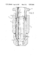
- FIG. 1 is a vertical cross-section through a gas shielded arc TIG torch constructed in accordance with the teaching of the present invention.
- FIG. 2 is an enlarged schematic view in cross section of the arrangement between the collet, collet body and torch cap of the gas shielded arc torch of FIG. 1.
- FIGS. 1 and 2 inclusive in which the TIG welding torch 10 of the present invention is shown including a torch head 12 neck 14 and handle 16 respectively.
- the torch head 12 has a barrel shaped geometry and lies at an inclined angle relative to the torch neck 14.
- the torch neck 14 is a narrow tubular section which couples the handle 16 to the head 12.
- the head 12 and neck 14 of the torch are preferably formed as an integral unit from an insulating material of any suitable plastic composition.
- the handle 16 also suitably of plastic extends from the neck 14 and is adapted to be held in the hand by an operator for manipulating the torch 10.
- the torch head 12 surrounds a collet assembly 18 for gripping and positioning an electrode E relative to the longitudinal axis of the head 12.
- the collet assembly 18 also serves to direct the passage of shielding gas from the neck 14 of the torch 10 through the torch head 12.
- the collet assembly 18 includes a collet body 20 and a collet 22.
- the collet 22 is supported within a bore 24 in the collet body 20 between the front end 26 of the collet body 20 and the lower end 27 of a manually adjustable torch cap 28.
- the front end 26 of the collet body 20 includes an opening 29 though which the electrode passes and further includes in cross section tapered wall surfaces 30 and 32 which intersect to form a vee having an included angle ⁇ in a range of between 30 to 75 degrees with sixty (60) degrees being preferred.
- the torch cap 28 is threadably engaged at its lower end 27 to the rear end 33 of the collet body 20.
- the lower end 27 of the torch cap 28 is tapered to provide in cross section beveled wall surfaces 34 and 35 which intersect to form a vee having an included angle ⁇ .
- the included angle ⁇ should be substantially larger than the included angle ⁇ .
- the included angle ⁇ is preferably about 90 degrees.
- the vee formed by the tapered wall surfaces 34 and 35 is arranged to form the mirror image of the vee between the tapered wall surfaces 30 and 32 with the apex of each coaxially aligned with the longitudinal axis of the torch head.
- the opposite ends 36 and 37 of the collet 22 is supported between the tapered wall surfaces 30, 32 and 34, 35 with the collet 22 held to a coaxial alignment with the collet body 20.
- the collet 22 is preferably fabricated from metal tubing of a desired diameter which is cut to a desired length and slotted at one end. Any conductive metal such as copper is preferred.
- the ends 36 and 37 of the collet form rectangular edges 38, 39, 40 and 41. No machining operation is necessary to bevel off any of the edges 38, 39, 40 and 41.
- the slot 44 in the collet 22 forms collet fingers 46, 48 for securely gripping an electrode E when a force is applied against the collet fingers. Since the collet 22 is simply a cylindrical tube having a slotted end the cost of manufacture is minimal.
- An alternate method for constructing the collet 22 is to start with a metal sheet and blank out a rectangular section with two or more slots 44.
- the rectangular section After blanking the rectangular section should be rolled into a tubular geometry. It can be seam welded at the mated edge if increased rigidity is needed. The resulting collet will have a tubular body as shown in FIG. 2 with straight squared off ends 36 and 37.
- the collet 22 is inserted in the bore 24 of the collet body 20 with the square edges 38 and 39 engaging the tapered surfaces 30 and 32 and with the square edges 40 and 41 engaging the tapered surfaces 34 and 35.
- the tapered surfaces 34 and 35 will automatically cause the collet 22 to slide until it is centered in the bore 24. Sliding should occur only at the unslotted end of the collet 22 and without twisting forces on the collet fingers 46, 48. This is realized by making the included angle ⁇ much larger than the included angle ⁇ and resulting in minimal twisting and more efficient transfer of current at the slotted end of the collet 22.
- the force applied by turning down the torch cap 28 is transmitted to the front end 26 of the collet body 20 to cause the fingers 46,48 of the collet 22 to move inwardly and grip the electrode E.
- the collet 22 is not restricted to one outside diameter size. In fact different outside diameter collets may be used without changing the size of the torch cap 28.
- the torch cap 28 includes a knob 50 for tightening the cap 28 and adjusting the degree of pressure applied to the collet 22.
- the torch cap 28 has a recessed bore 52 which is concentric with the longitudinal axis of the torch head 12 and is adapted to accommodate the opposite end of the electrode E.
- the lower end 27 of the torch cap 28 is machined down to a smaller diameter than the outside diameter of the collet body 20 to provide a clearance 56 between the torch cap 28 and the rear end 33 of the collet body 20 which allows the cap 28 to be controllably tightened into the collet body 20.
- the diameter of the collet 22 is smaller than the diameter of the bore 24 for providing an annulus 48 therebetween.
- Shielding gas is directed from a supply tube 52 extending from the neck 14 of the torch 10 into the annulus 48.
- the supply tube 52 engages a counterbore 53 in the collet body with the annulus 48 communicating with the supply tube through a drilled opening 55 in the collet body.
- the supply tube 52 is of an electrically conducting material for also supplying electrical power to the metal collet body from a source of power (not shown) in a conventional fashion.
- the collet body 20 also includes a plurality of gas discharge holes 60 arranged circumferentially about the collet body 20 adjacent to the front end 26.
- a conventional ceramic cup 62 is mounted over the collet body 20. The shielding gas is discharged from the annulus 48 through the holes 60 into the ceramic cup 62 whereupon it is redirected to form a shielding gas envelope about the electrode E.
- the electrode E may be inserted into the collet 22 through the front end 26 of the collet body 20 provided the torch cap 28 is loosened. Alternatively the electrode E may be inserted through the rear end of the torch 10 by removal of the torch cap 28.
- the squared off ends 36 and 37 of the collet 22 will after repeated usage cause one or more of the edges 38, 39, 40 and 41 to form a beveled near surface adjacent the corresponding tapered surfaces 30, 32, 34 and 35. Accordingly, although the edges may be machined to a beveled taper this operation is unnecessary.
Abstract
Description
Claims (7)
Priority Applications (1)
| Application Number | Priority Date | Filing Date | Title |
|---|---|---|---|
| US06/566,830 US4543461A (en) | 1983-12-29 | 1983-12-29 | Gas shielded arc torch and collet assembly |
Applications Claiming Priority (1)
| Application Number | Priority Date | Filing Date | Title |
|---|---|---|---|
| US06/566,830 US4543461A (en) | 1983-12-29 | 1983-12-29 | Gas shielded arc torch and collet assembly |
Publications (1)
| Publication Number | Publication Date |
|---|---|
| US4543461A true US4543461A (en) | 1985-09-24 |
Family
ID=24264546
Family Applications (1)
| Application Number | Title | Priority Date | Filing Date |
|---|---|---|---|
| US06/566,830 Expired - Fee Related US4543461A (en) | 1983-12-29 | 1983-12-29 | Gas shielded arc torch and collet assembly |
Country Status (1)
| Country | Link |
|---|---|
| US (1) | US4543461A (en) |
Cited By (12)
| Publication number | Priority date | Publication date | Assignee | Title |
|---|---|---|---|---|
| US4644131A (en) * | 1986-04-22 | 1987-02-17 | The Ohio State University Research Foundation | Electrode support for gas arc welding torch having coaxial vision |
| US4924053A (en) * | 1988-12-05 | 1990-05-08 | The United States Of America As Represented By The Administrator Of The National Aeronautics And Space Administration | Electrode carrying wire for GTAW welding |
| DE4411967A1 (en) * | 1994-04-07 | 1995-10-12 | Kabelmetal Electro Gmbh | Device for welding thin sheets which pass under a fixed water-cooled welding head |
| US5798493A (en) * | 1996-05-14 | 1998-08-25 | Heller, Sr.; Walter R. | Fixed welding apparatus and method |
| US6399913B1 (en) * | 2000-11-01 | 2002-06-04 | Illinois Tool Works Inc. | Ergonomic TIG torch |
| EP1287935A1 (en) * | 2001-08-24 | 2003-03-05 | Parweld Limited | A welding torch for use in gas metal ARC welding |
| US20040050822A1 (en) * | 2002-09-16 | 2004-03-18 | Samler Gary R. | Welding torch having integral collet and collet body and method of operating same |
| US20040050824A1 (en) * | 2002-09-16 | 2004-03-18 | Samler Gary R. | Welding torch having collet and backcap adapted for securing engagement and method for operating same |
| US20050121419A1 (en) * | 2003-12-05 | 2005-06-09 | Samler Gary R. | System and method for securing a welding electrode to a welding torch |
| US20090161212A1 (en) * | 2007-12-21 | 2009-06-25 | Gough Yuma E | Weld viewing |
| US9789560B2 (en) | 2010-05-12 | 2017-10-17 | Jesse Rogers | Arc welding torch having a variable electrode receiver |
| CN110548971A (en) * | 2019-09-12 | 2019-12-10 | 安徽信息工程学院 | Special welding gun |
Citations (5)
| Publication number | Priority date | Publication date | Assignee | Title |
|---|---|---|---|---|
| US3053968A (en) * | 1960-04-25 | 1962-09-11 | Union Carbide Corp | Method and apparatus for arc working with gas shields having coherentstreaming |
| US3272958A (en) * | 1964-03-18 | 1966-09-13 | Union Carbide Corp | Gas shielded arc torch |
| US3522406A (en) * | 1969-02-18 | 1970-08-04 | Air Prod & Chem | Welding torch gas control valve |
| US3794806A (en) * | 1969-06-09 | 1974-02-26 | Air Prod & Chem | Plasma arc welding torch |
| US4309588A (en) * | 1980-08-27 | 1982-01-05 | Union Carbide Corporation | Air cooled gas shielded arc torch |
-
1983
- 1983-12-29 US US06/566,830 patent/US4543461A/en not_active Expired - Fee Related
Patent Citations (5)
| Publication number | Priority date | Publication date | Assignee | Title |
|---|---|---|---|---|
| US3053968A (en) * | 1960-04-25 | 1962-09-11 | Union Carbide Corp | Method and apparatus for arc working with gas shields having coherentstreaming |
| US3272958A (en) * | 1964-03-18 | 1966-09-13 | Union Carbide Corp | Gas shielded arc torch |
| US3522406A (en) * | 1969-02-18 | 1970-08-04 | Air Prod & Chem | Welding torch gas control valve |
| US3794806A (en) * | 1969-06-09 | 1974-02-26 | Air Prod & Chem | Plasma arc welding torch |
| US4309588A (en) * | 1980-08-27 | 1982-01-05 | Union Carbide Corporation | Air cooled gas shielded arc torch |
Cited By (17)
| Publication number | Priority date | Publication date | Assignee | Title |
|---|---|---|---|---|
| US4644131A (en) * | 1986-04-22 | 1987-02-17 | The Ohio State University Research Foundation | Electrode support for gas arc welding torch having coaxial vision |
| US4924053A (en) * | 1988-12-05 | 1990-05-08 | The United States Of America As Represented By The Administrator Of The National Aeronautics And Space Administration | Electrode carrying wire for GTAW welding |
| DE4411967A1 (en) * | 1994-04-07 | 1995-10-12 | Kabelmetal Electro Gmbh | Device for welding thin sheets which pass under a fixed water-cooled welding head |
| US5798493A (en) * | 1996-05-14 | 1998-08-25 | Heller, Sr.; Walter R. | Fixed welding apparatus and method |
| US6399913B1 (en) * | 2000-11-01 | 2002-06-04 | Illinois Tool Works Inc. | Ergonomic TIG torch |
| EP1287935A1 (en) * | 2001-08-24 | 2003-03-05 | Parweld Limited | A welding torch for use in gas metal ARC welding |
| US20030052111A1 (en) * | 2001-08-24 | 2003-03-20 | Parker Tracy Stephen | Welding torch for use in gas metal arc welding |
| US6740848B2 (en) | 2001-08-24 | 2004-05-25 | Parweld Limited | Welding torch for use in gas metal arc welding |
| US20040050824A1 (en) * | 2002-09-16 | 2004-03-18 | Samler Gary R. | Welding torch having collet and backcap adapted for securing engagement and method for operating same |
| US20040050822A1 (en) * | 2002-09-16 | 2004-03-18 | Samler Gary R. | Welding torch having integral collet and collet body and method of operating same |
| US6884958B2 (en) * | 2002-09-16 | 2005-04-26 | Illinois Tool Works Inc. | Welding torch having integral collet and collet body and method of operating same |
| US6995331B2 (en) * | 2002-09-16 | 2006-02-07 | Illinois Tool Works Inc. | Welding torch having collet and backcap adapted for securing engagement and method for operating same |
| US20050121419A1 (en) * | 2003-12-05 | 2005-06-09 | Samler Gary R. | System and method for securing a welding electrode to a welding torch |
| US7053329B2 (en) * | 2003-12-05 | 2006-05-30 | Illinois Tool Works Inc. | System and method for securing a welding electrode to a welding torch |
| US20090161212A1 (en) * | 2007-12-21 | 2009-06-25 | Gough Yuma E | Weld viewing |
| US9789560B2 (en) | 2010-05-12 | 2017-10-17 | Jesse Rogers | Arc welding torch having a variable electrode receiver |
| CN110548971A (en) * | 2019-09-12 | 2019-12-10 | 安徽信息工程学院 | Special welding gun |
Similar Documents
| Publication | Publication Date | Title |
|---|---|---|
| US4543461A (en) | Gas shielded arc torch and collet assembly | |
| CA2991710C (en) | Tip-retention device for use with a welding system | |
| EP0477234B1 (en) | System for use in electrode welding and gas/arc welding | |
| US6987237B2 (en) | Electrodes and nozzles having improved connection and quick release | |
| EP0501277B1 (en) | Plasma arc torch | |
| US2468807A (en) | Water-cooled gas blanketed arcwelding torch | |
| GB2057951A (en) | Plasma arc torch and nozzle assembly combination | |
| EP3357626A1 (en) | Tip-retention device for use with a welding system | |
| US4194107A (en) | Welding tip | |
| US4250373A (en) | Transferred type plasma torch | |
| US2512707A (en) | Gas-shielded arc welding torch | |
| CA1067584A (en) | Method and torch for sustaining multiple coaxial arcs | |
| US2512706A (en) | Water-cooled gas-blanketed arc welding torch | |
| US2685631A (en) | Gas shielded arc welding torch | |
| US3588464A (en) | Dual electrode torch for manual welding | |
| US6626615B2 (en) | Chuck for chucking a small bit and table drill with the same | |
| US4367393A (en) | Gas shielded plasma arc torch with improved collet | |
| US6429406B1 (en) | Contact tip | |
| DE102017121722B4 (en) | Burner body for thermal joining, burner with burner body and joining device | |
| EP0938395B1 (en) | Plasma torch | |
| DE1440623B1 (en) | Inert gas arc torch | |
| KR101698191B1 (en) | tungsten inert gas arc welders having length adjustable tungsten electrode | |
| US4461948A (en) | Collet system for arc welding torches | |
| US5900167A (en) | Narrow prep MIG welding | |
| US5798493A (en) | Fixed welding apparatus and method |
Legal Events
| Date | Code | Title | Description |
|---|---|---|---|
| AS | Assignment |
Owner name: UNION CARBIDE CORPORATION, OLD RIDGEBURY ROAD, DAN Free format text: ASSIGNMENT OF ASSIGNORS INTEREST.;ASSIGNOR:HILL, CLIFFORD W.;REEL/FRAME:004254/0058 Effective date: 19841219 |
|
| AS | Assignment |
Owner name: L-TEC COMPANY C/O INTEGRATED RESOURCES, INC., 666 Free format text: ASSIGNMENT OF ASSIGNORS INTEREST.;ASSIGNOR:UNION CARBIDE CORPORATION A NY CORP;REEL/FRAME:004429/0767 Effective date: 19850712 |
|
| AS | Assignment |
Owner name: SECURITY PACIFIC BUSINESS CREDIT INC., A DE CORP. Free format text: SECURITY INTEREST;ASSIGNOR:L-TEC COMPANY A NY LIMITED PARTNERSHIP;REEL/FRAME:004445/0860 Effective date: 19850716 |
|
| AS | Assignment |
Owner name: L-TEC COMPANY, EBENEEZER ROAD, POST OFFICE BOX F-6 Free format text: ASSIGNMENT OF ASSIGNORS INTEREST.;ASSIGNOR:UNION CARBIDE CORPORATION, A CORP OF NY.;REEL/FRAME:004610/0384 Effective date: 19860828 Owner name: L-TEC COMPANY, SOUTH CAROLINA Free format text: ASSIGNMENT OF ASSIGNORS INTEREST;ASSIGNOR:UNION CARBIDE CORPORATION, A CORP OF NY.;REEL/FRAME:004610/0384 Effective date: 19860828 |
|
| REMI | Maintenance fee reminder mailed | ||
| LAPS | Lapse for failure to pay maintenance fees | ||
| STCH | Information on status: patent discontinuation |
Free format text: PATENT EXPIRED DUE TO NONPAYMENT OF MAINTENANCE FEES UNDER 37 CFR 1.362 |
|
| FP | Lapsed due to failure to pay maintenance fee |
Effective date: 19890924 |