US4583465A - Railway wheel apparatus for a road vehicle - Google Patents
Railway wheel apparatus for a road vehicle Download PDFInfo
- Publication number
- US4583465A US4583465A US06/665,761 US66576184A US4583465A US 4583465 A US4583465 A US 4583465A US 66576184 A US66576184 A US 66576184A US 4583465 A US4583465 A US 4583465A
- Authority
- US
- United States
- Prior art keywords
- toggle
- pair
- structures
- axle
- toggle structures
- Prior art date
- Legal status (The legal status is an assumption and is not a legal conclusion. Google has not performed a legal analysis and makes no representation as to the accuracy of the status listed.)
- Expired - Lifetime
Links
Images


Classifications
-
- B—PERFORMING OPERATIONS; TRANSPORTING
- B60—VEHICLES IN GENERAL
- B60F—VEHICLES FOR USE BOTH ON RAIL AND ON ROAD; AMPHIBIOUS OR LIKE VEHICLES; CONVERTIBLE VEHICLES
- B60F1/00—Vehicles for use both on rail and on road; Conversions therefor
- B60F1/04—Vehicles for use both on rail and on road; Conversions therefor with rail and road wheels on different axles
- B60F1/043—Vehicles comprising own propelling units
Definitions
- This invention relates to apparatus for mounting at the rear of a road vehicle so as to adapt the vehicle for operation on railway tracks whereby flanged wheels and an associated axle are lowered and raised relative to the vehicle frame.
- Known devices for adapting a road vehicle for use on railway tracks ordinarily contemplate the provsion of flanged wheels pivotally mounted on the vehicle frame and arranged to swing through an arc so as to raise or lower the flanged wheels as desired.
- Such prior art structures project outwardly from the vehicle frame and thus require additional space and are not well adapted for sidewise movement relative to the vehicle frame so as to accommodate minor misalignment between the road vehicle wheels and the railway tracks.
- flanged wheels and their associated axle are raised and lowered vertically relative to the vehicle frame instead of being moved through an arc.
- the apparatus includes toggle structures which are arranged to swing in planes which are disposed in general alignment with and parallel to the axle on which the flanged railway wheels are mounted so that sidewise movement of the flanged wheels relative to the vehicle frame and to the railroad tracks is readily accomplished thus avoiding tedious alignment of the vehicle road wheels with the railway tracks.
- a pair of flanged wheels mounted in spaced relation on an axle are interconnected with a road vehicle frame by means of a first pair of spaced apart toggle structures which are pivotally connected at one end thereof to the axle together with a second pair of spaced apart toggle structures which are pivotally connected at one end thereof respectively to the other ends of the first pair of toggle structures and in turn are pivotally connected at their other ends to the vehicle frame whereby extension of said toggle structures into substantial alignment with each other effects downward lowering of the axle and wheels and angular movement of the toggle structures relative to each other effects retraction of such structures whereby the axle and wheels are raised and fluid motors for extending and retracting the toggle structures relative to each other.
- FIG. 1 is a perspective view of a road vehicle to the rear end of which a railway wheel apparatus constructed according to this invention is mounted;
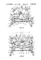
- FIG. 2 is a view from the rear of apparatus formed according to this invention and which depicts the flanged wheels and their associated axle spaced to the left side of railway tracks;
- FIG. 3 is a view similar to FIG. 2 but which shows the flanged wheels and axles spaced to the right side of the railway tracks;
- FIG. 4 shows the flanged wheels properly aligned with and mounted on the railway tracks
- FIG. 5 depicts apparatus in its retracted position
- FIG. 6 shows the apparatus in its lowered or extended position
- FIG. 7 shows a locking pin provided according to a feature of the invention.
- FIG. 8 is an enlarged cross sectional view taken on the line designated 8--8 in FIG. 6.
- the numeral 1 generally designates a truck on which railway wheel apparatus 2 formed according to this invention is mounted.
- the numeral 3 designates a part of the frame of vehicle 1.
- a pair of support elements 4 and 5 are secured as by suitable bolts 6 to the frame 3.
- a base plate 7 is bolted or otherwise secured to the lower portions of support elements 4 and 5.
- Flanged wheels 8 and 9 are mounted on axle 10 and are adapted for cooperation with railway tracks 11 and 12.
- Axle 10 is interconnected with the frame 3 and support elements 4 and 5 as well as base plate 7 by means of a first pair of toggle links 13 and 14 together with a second pair of toggle links 15 and 16.
- Toggle link 13 is pivotally connected at 17 to axle 10 while toggle link 14 is pivotally connected at 18 to axle 10.
- Toggle structure 13 is pivotally connected with toggle structure 15 at pivot 19 to form one toggle while toggle structure 14 is pivotally connected to toggle structure 16 at pivot 20 to form another toggle.
- Toggle structure 15 is pivotally connected with the base plate 7 and support element 4 by pivot 21 while toggle structure 16 is pivotally connected with support element 5 and base plate 7 at pivot 22.
- toggle structure 13 comprises a pair of spaced coincidental toggle links 13a and 13b while toggle structure 15 comprises a pair of spaced coincidental toggle links 15a and 15b.
- toggle structure 14 includes a pair of spaced coincidental toggle links 14a and 14b while toggle structure 16 includes a pair of spaced coincidental toggle links 16a and 16b.
- operating means in the form of a fluid motor generally designated at 25 is provided and includes a cylinder 25a and a piston not shown but having a piston rod 25b.
- the right hand end of piston rod 25b is pivotally connected at pivot 26 with a structure 27 secured by welding or otherwise to the axle 10 at approximately the mid point thereof.
- Cylinder 25a is partially between links 15a and 15b and between toggle links 13a and 13b and is pivotally connected thereto by pin 19 so that outward movement of piston rod 25b relative to cylinder 25a tends to swing toggle structure 15 in a clockwise direction about pivot 21 while such operating movement imparts swinging movement to toggle structure 13 in a counterclockwise direction about pivot 17 so that ultimately these structures 13 and 17 occupy the positions as shown in FIG. 4.
- a similar fluid motor 31 is associated with toggle structures 14 and 16 and includes a cylinder 31a and a piston not shown and an associated piston rod 31b.
- Piston rod 31b is pivotally connected at 32 to structure 27 and the cylinder 31a is pivotally connected at pivot 16a.
- Control of fluid motor 31 is by means of conduits 33 and 34 together with manually operable control lever 35.
- the apparatus With the railway wheel apparatus disposed in its uppermost position as represented by FIG. 5, the apparatus is lowered by supplying fluid pressure such as hydraulic liquid to the cylinders 25a and 31a through conduits 27 and 33 thereby to extend or straighten the toggle structures 13, 15 and 14, 16 so as to cause the parts to occupy the positions represented in FIG. 4 at which the flanged wheels 8 and 9 are in cooperative contact with the rails 11 and 12 respectively.
- fluid pressure such as hydraulic liquid
- toggle structure 13,15 and 14,16 operate in a plane parallel to an in general alignment with the axle 10, these structures do not protrude outwardly to any significant extent beyond the frame 3 of the vehicle 1 and parts associated therewith.
- this action of the cooperating parts imparts up and down vertical movement to the flanged wheels 8 and 9 and the associated axle 10 rather than causing movement of the wheels and axle through an arcuate path as is the practice with known structures.
- the vehicle road wheels be precisely aligned with the railway tracks when the vehicle is positioned to allow the flanged wheels to move downwardly and into engagement with the railway tracks.
- This aspect of the invention is represented at FIGS. 2 and 3.
- the road vehicle wheels are not precisely aligned with the vehicle tracks 11 and 12 and lowering of the axle and flanged wheels 8 and 9 may be accompanied by sidewise movement of the axle and wheels simply by appropriate control of the manual levers 30 and 35.
- the flanged wheels 8 and 9 are to the left of the railway tracks 11 and 12.
- mechanical interlocking means is provided and includes a locking aperture 40 formed in at least one link comprising the toggle structure such as 16 which when disposed in the extended or lowered position as shown in FIG. 6, coincides with an aperture not shown formed in one of the links such as 14a forming a part of toggle structure 14.
- a locking element 42 is inserted so as to secure these parts against relative movement. The locking element, as shown in FIG.
- a holding ledge 46 is secured to the link such as 16a, the leg 47 of device 46 being welded to the link 16a and the ledge portion 48 extending toward the aperture 40.
- An abutment element 50 is fixedly mounted on a part of two of said toggle structures and engages a part of the other associated toggle structure for arresting relative movement thereof at the approximate limit of extended movement of the toggle structures.
- railway wheel apparatus for a road vehicle formed according to this invention is particulalry advantageous because it provides for lowering flanged wheels vertically rather than through an outwardly swinging arc and thus avoids interference with other objects and conserves space underneath the vehicle body.
- the invention also is especially adapted to provide for lateral shifting of the flanged wheels and the associated axle relative to the road vehicle whereby precise alignment of the road vehicle wheels with the railway tracks is not necessary, thereby greatly facilitating easy transition from roadway service to service on railway tracks.
Abstract
Description
Claims (10)
Priority Applications (1)
| Application Number | Priority Date | Filing Date | Title |
|---|---|---|---|
| US06/665,761 US4583465A (en) | 1984-10-29 | 1984-10-29 | Railway wheel apparatus for a road vehicle |
Applications Claiming Priority (1)
| Application Number | Priority Date | Filing Date | Title |
|---|---|---|---|
| US06/665,761 US4583465A (en) | 1984-10-29 | 1984-10-29 | Railway wheel apparatus for a road vehicle |
Publications (1)
| Publication Number | Publication Date |
|---|---|
| US4583465A true US4583465A (en) | 1986-04-22 |
Family
ID=24671474
Family Applications (1)
| Application Number | Title | Priority Date | Filing Date |
|---|---|---|---|
| US06/665,761 Expired - Lifetime US4583465A (en) | 1984-10-29 | 1984-10-29 | Railway wheel apparatus for a road vehicle |
Country Status (1)
| Country | Link |
|---|---|
| US (1) | US4583465A (en) |
Cited By (22)
| Publication number | Priority date | Publication date | Assignee | Title |
|---|---|---|---|---|
| US5154124A (en) * | 1991-09-05 | 1992-10-13 | Harsco Corporation | Rail engagement apparatus which uses vehicle supension |
| US5186109A (en) * | 1991-10-16 | 1993-02-16 | Harsco Corporation | Side shift railway guide wheel apparatus for rail/highway conversion with V-shaped automatic centering surfaces for centering vehicle relative to the rails |
| US5586507A (en) * | 1995-07-24 | 1996-12-24 | Harsco Corporation | Rail guide wheel apparatus with double overcenter linkage |
| GB2306416A (en) * | 1995-10-27 | 1997-05-07 | Harsco Corp | Vertically actuated rail guide wheels |
| US5802980A (en) * | 1997-04-07 | 1998-09-08 | Dfm Enterprises, Inc. | Vehicle drive system for road and railroad track |
| GB2337492A (en) * | 1995-10-27 | 1999-11-24 | Harsco Corp | Vertically actuated rail guide wheels with joystick controlled side shifting |
| US6298792B1 (en) * | 2000-02-24 | 2001-10-09 | Essco | Hi-rail wheel assembly for improved traction |
| US6533222B1 (en) | 2002-01-16 | 2003-03-18 | Gaetano D. Brooks | Railway vehicle safety shunt system |
| US6622635B2 (en) * | 1998-01-12 | 2003-09-23 | Autran Corp. | Automated transportation system |
| US20060027136A1 (en) * | 2004-08-06 | 2006-02-09 | Rafna Industries Limited | Rail wheel attachment for a vehicle |
| CN1309610C (en) * | 2004-05-28 | 2007-04-11 | 上海磁浮交通工程技术研究中心 | Magnetic suspension track inspection railcar |
| CN1317152C (en) * | 2004-05-28 | 2007-05-23 | 上海磁浮交通工程技术研究中心 | Magnetic suspension track inspection railcar chassis with floated steering system |
| CN1323885C (en) * | 2004-10-28 | 2007-07-04 | 上海磁浮交通发展有限公司 | Mixed power electric driving magnetic suspension rail polling vehicle with rail detection system |
| WO2009073899A2 (en) * | 2007-12-03 | 2009-06-11 | Johannes Jacobus Fourie | Railway converter for a vehicle |
| USD666634S1 (en) * | 2010-10-27 | 2012-09-04 | Reeve Vernon L | Set of wheels for quilting machine |
| US20140200753A1 (en) * | 2013-01-14 | 2014-07-17 | Frank E. Bunn | Rail Bus Transportation Network Loop System |
| US20140261067A1 (en) * | 2013-03-15 | 2014-09-18 | Diversified Metal Fabricators, Inc. | Rail gear |
| CN106494165A (en) * | 2016-10-25 | 2017-03-15 | 徐洪恩 | A kind of dual-purpose transport vehicle of the variable Rail Highway of wheelspan |
| US10696113B2 (en) | 2017-09-07 | 2020-06-30 | Custom Truck & Equipment LLC | Railcar-mover vehicle |
| US20210086574A1 (en) * | 2019-09-20 | 2021-03-25 | Diversified Metal Fabricators, Inc. | Rear railgear and railgear pin-off systems |
| US11077731B2 (en) * | 2017-06-27 | 2021-08-03 | Technologie Continental Railworks I Inc. / Contine | Vertical hi-rail device |
| US11396254B2 (en) | 2017-09-07 | 2022-07-26 | Custom Truck & Equipment LLC | Railcar-mover vehicle |
Citations (10)
| Publication number | Priority date | Publication date | Assignee | Title |
|---|---|---|---|---|
| DE10970C (en) * | C. BERNHEIM in Cassel, Frankfurterstrafse 15 | Hookah | ||
| US1501744A (en) * | 1922-11-22 | 1924-07-15 | Brilhart Samuel Bower | Car truck |
| US2116525A (en) * | 1936-02-12 | 1938-05-10 | Milton A Luce | Motor-rail vehicle |
| US2583072A (en) * | 1944-09-09 | 1952-01-22 | Wilson John Hart | Derrick |
| US2896548A (en) * | 1954-07-28 | 1959-07-28 | Andrew N Obes | Freight transfer terminal and transfer dolly |
| US3704027A (en) * | 1970-01-08 | 1972-11-28 | Sanfrancisco Cayetano Roque La | Suspension system for motor vehicles |
| US3804025A (en) * | 1972-05-22 | 1974-04-16 | Auto Crane Co | Convertible rail-highway vehicle |
| US3808693A (en) * | 1971-10-04 | 1974-05-07 | Plasser Bahnbaumasch Franz | Mobile track gage surveying apparatus |
| US4077328A (en) * | 1976-06-11 | 1978-03-07 | Glenn Taylor | Rotary dump |
| US4488494A (en) * | 1983-02-11 | 1984-12-18 | Powell Sr Parks L | Railway wheel conversion apparatus for road vehicles |
-
1984
- 1984-10-29 US US06/665,761 patent/US4583465A/en not_active Expired - Lifetime
Patent Citations (11)
| Publication number | Priority date | Publication date | Assignee | Title |
|---|---|---|---|---|
| DE10970C (en) * | C. BERNHEIM in Cassel, Frankfurterstrafse 15 | Hookah | ||
| US1501744A (en) * | 1922-11-22 | 1924-07-15 | Brilhart Samuel Bower | Car truck |
| US2116525A (en) * | 1936-02-12 | 1938-05-10 | Milton A Luce | Motor-rail vehicle |
| US2583072A (en) * | 1944-09-09 | 1952-01-22 | Wilson John Hart | Derrick |
| US2896548A (en) * | 1954-07-28 | 1959-07-28 | Andrew N Obes | Freight transfer terminal and transfer dolly |
| US3704027A (en) * | 1970-01-08 | 1972-11-28 | Sanfrancisco Cayetano Roque La | Suspension system for motor vehicles |
| US3808693A (en) * | 1971-10-04 | 1974-05-07 | Plasser Bahnbaumasch Franz | Mobile track gage surveying apparatus |
| US3804025A (en) * | 1972-05-22 | 1974-04-16 | Auto Crane Co | Convertible rail-highway vehicle |
| US4077328A (en) * | 1976-06-11 | 1978-03-07 | Glenn Taylor | Rotary dump |
| US4077328B1 (en) * | 1976-06-11 | 1986-03-18 | ||
| US4488494A (en) * | 1983-02-11 | 1984-12-18 | Powell Sr Parks L | Railway wheel conversion apparatus for road vehicles |
Cited By (32)
| Publication number | Priority date | Publication date | Assignee | Title |
|---|---|---|---|---|
| US5154124A (en) * | 1991-09-05 | 1992-10-13 | Harsco Corporation | Rail engagement apparatus which uses vehicle supension |
| US5186109A (en) * | 1991-10-16 | 1993-02-16 | Harsco Corporation | Side shift railway guide wheel apparatus for rail/highway conversion with V-shaped automatic centering surfaces for centering vehicle relative to the rails |
| AU655052B2 (en) * | 1991-10-16 | 1994-12-01 | Harsco Corporation | Side shift railway guide wheel apparatus |
| AU661430B2 (en) * | 1991-10-16 | 1995-07-20 | Harsco Corporation | Side shift railway guide wheel apparatus |
| US5586507A (en) * | 1995-07-24 | 1996-12-24 | Harsco Corporation | Rail guide wheel apparatus with double overcenter linkage |
| US5660115A (en) * | 1995-10-27 | 1997-08-26 | Harsco Corporation | Vertically actuated rail guide wheels |
| GB2306416A (en) * | 1995-10-27 | 1997-05-07 | Harsco Corp | Vertically actuated rail guide wheels |
| GB2337492A (en) * | 1995-10-27 | 1999-11-24 | Harsco Corp | Vertically actuated rail guide wheels with joystick controlled side shifting |
| GB2337492B (en) * | 1995-10-27 | 2000-02-16 | Harsco Corp | Vertically actuated rail guide wheels |
| GB2306416B (en) * | 1995-10-27 | 2000-02-23 | Harsco Corp | Vertically actuated rail guide wheels |
| US5802980A (en) * | 1997-04-07 | 1998-09-08 | Dfm Enterprises, Inc. | Vehicle drive system for road and railroad track |
| US6622635B2 (en) * | 1998-01-12 | 2003-09-23 | Autran Corp. | Automated transportation system |
| US6298792B1 (en) * | 2000-02-24 | 2001-10-09 | Essco | Hi-rail wheel assembly for improved traction |
| US6533222B1 (en) | 2002-01-16 | 2003-03-18 | Gaetano D. Brooks | Railway vehicle safety shunt system |
| CN1317152C (en) * | 2004-05-28 | 2007-05-23 | 上海磁浮交通工程技术研究中心 | Magnetic suspension track inspection railcar chassis with floated steering system |
| CN1309610C (en) * | 2004-05-28 | 2007-04-11 | 上海磁浮交通工程技术研究中心 | Magnetic suspension track inspection railcar |
| US20060027136A1 (en) * | 2004-08-06 | 2006-02-09 | Rafna Industries Limited | Rail wheel attachment for a vehicle |
| CN1323885C (en) * | 2004-10-28 | 2007-07-04 | 上海磁浮交通发展有限公司 | Mixed power electric driving magnetic suspension rail polling vehicle with rail detection system |
| WO2009073899A2 (en) * | 2007-12-03 | 2009-06-11 | Johannes Jacobus Fourie | Railway converter for a vehicle |
| WO2009073899A3 (en) * | 2007-12-03 | 2009-09-03 | Johannes Jacobus Fourie | Railway converter for a vehicle |
| USD666634S1 (en) * | 2010-10-27 | 2012-09-04 | Reeve Vernon L | Set of wheels for quilting machine |
| US10286924B2 (en) * | 2013-01-14 | 2019-05-14 | Frank E. Bunn | Rail bus transportation network loop system |
| US20140200753A1 (en) * | 2013-01-14 | 2014-07-17 | Frank E. Bunn | Rail Bus Transportation Network Loop System |
| US20140261067A1 (en) * | 2013-03-15 | 2014-09-18 | Diversified Metal Fabricators, Inc. | Rail gear |
| US9643463B2 (en) * | 2013-03-15 | 2017-05-09 | Diversified Metal Fabricators, Inc. | Rail gear |
| CN106494165A (en) * | 2016-10-25 | 2017-03-15 | 徐洪恩 | A kind of dual-purpose transport vehicle of the variable Rail Highway of wheelspan |
| CN106494165B (en) * | 2016-10-25 | 2019-03-08 | 付万贤 | A kind of variable dual-purpose transport vehicle of Rail Highway of wheelspan |
| US11077731B2 (en) * | 2017-06-27 | 2021-08-03 | Technologie Continental Railworks I Inc. / Contine | Vertical hi-rail device |
| US10696113B2 (en) | 2017-09-07 | 2020-06-30 | Custom Truck & Equipment LLC | Railcar-mover vehicle |
| US11396254B2 (en) | 2017-09-07 | 2022-07-26 | Custom Truck & Equipment LLC | Railcar-mover vehicle |
| US20210086574A1 (en) * | 2019-09-20 | 2021-03-25 | Diversified Metal Fabricators, Inc. | Rear railgear and railgear pin-off systems |
| US11752818B2 (en) * | 2019-09-20 | 2023-09-12 | Diversified Metal Fabricators, Inc. | Rear railgear and railgear pin-off systems |
Similar Documents
| Publication | Publication Date | Title |
|---|---|---|
| US4583465A (en) | Railway wheel apparatus for a road vehicle | |
| AU644447B2 (en) | Rail bogie | |
| US2231875A (en) | Snowplcw | |
| CN106956915B (en) | Turnover machine | |
| AU658941B2 (en) | Truck mounted tie exchanger with self-aligning tie clamp | |
| US4951573A (en) | Tie remover and inserter | |
| US4103622A (en) | Ballast tamping machine | |
| US4520735A (en) | Convertible rail-highway maintenance vehicle | |
| US3762337A (en) | Railed vehicle-carrier system | |
| US3804025A (en) | Convertible rail-highway vehicle | |
| JPH0858640A (en) | Fifth ring coupling device capable of lifting and lowering by power | |
| CA2188708C (en) | Vertically actuated rail guide wheels | |
| JP3162597U (en) | Rotating base rotation mechanism of railroad vehicle | |
| US4392433A (en) | Railway maintenance machine | |
| US3299833A (en) | Externally engaging lifting jack frame | |
| US3540381A (en) | Locomotive with elevatable chassis and coupler | |
| JPH06219276A (en) | Derailment recovery device for railway maintenance vehicle | |
| JP2006248488A (en) | Trailer truck for railway work and method for transferring trailer truck onto track | |
| US4421034A (en) | Compact bidirectionally operative tie exchanging apparatus | |
| EP0728077B1 (en) | A method of transferring a vehicle for operation on both road and railroad track from road to railroad operation | |
| GB2146616A (en) | Lifting jack | |
| KR100495029B1 (en) | Self rerailing device of motor car | |
| JP4601483B2 (en) | Track work vehicle and derailment recovery method | |
| CN111979856A (en) | Track lifting and lining device and track lifting and lining operation method | |
| US3756163A (en) | Convertible vehicle with flange and rubber tired wheels |
Legal Events
| Date | Code | Title | Description |
|---|---|---|---|
| STCF | Information on status: patent grant |
Free format text: PATENTED CASE |
|
| AS | Assignment |
Owner name: DIVERSIFIED METAL FABRICATORS, INC., 665 PYLANT ST Free format text: ASSIGNMENT OF ASSIGNORS INTEREST.;ASSIGNOR:POWELL, PARKS L. JR.;REEL/FRAME:004766/0519 Effective date: 19870529 Owner name: DIVERSIFIED METAL FABRICATORS, INC.,GEORGIA Free format text: ASSIGNMENT OF ASSIGNORS INTEREST;ASSIGNOR:POWELL, PARKS L. JR.;REEL/FRAME:004766/0519 Effective date: 19870529 |
|
| FPAY | Fee payment |
Year of fee payment: 4 |
|
| FEPP | Fee payment procedure |
Free format text: PAYOR NUMBER ASSIGNED (ORIGINAL EVENT CODE: ASPN); ENTITY STATUS OF PATENT OWNER: SMALL ENTITY |
|
| FPAY | Fee payment |
Year of fee payment: 8 |
|
| FEPP | Fee payment procedure |
Free format text: PAYER NUMBER DE-ASSIGNED (ORIGINAL EVENT CODE: RMPN); ENTITY STATUS OF PATENT OWNER: SMALL ENTITY |
|
| REMI | Maintenance fee reminder mailed | ||
| FPAY | Fee payment |
Year of fee payment: 12 |
|
| SULP | Surcharge for late payment |