US4664254A - Shipping container for works of art - Google Patents
Shipping container for works of art Download PDFInfo
- Publication number
- US4664254A US4664254A US06/740,868 US74086885A US4664254A US 4664254 A US4664254 A US 4664254A US 74086885 A US74086885 A US 74086885A US 4664254 A US4664254 A US 4664254A
- Authority
- US
- United States
- Prior art keywords
- art
- strap
- work
- shipping container
- plate member
- Prior art date
- Legal status (The legal status is an assumption and is not a legal conclusion. Google has not performed a legal analysis and makes no representation as to the accuracy of the status listed.)
- Expired - Fee Related
Links
Images


Classifications
-
- B—PERFORMING OPERATIONS; TRANSPORTING
- B65—CONVEYING; PACKING; STORING; HANDLING THIN OR FILAMENTARY MATERIAL
- B65D—CONTAINERS FOR STORAGE OR TRANSPORT OF ARTICLES OR MATERIALS, e.g. BAGS, BARRELS, BOTTLES, BOXES, CANS, CARTONS, CRATES, DRUMS, JARS, TANKS, HOPPERS, FORWARDING CONTAINERS; ACCESSORIES, CLOSURES, OR FITTINGS THEREFOR; PACKAGING ELEMENTS; PACKAGES
- B65D81/00—Containers, packaging elements, or packages, for contents presenting particular transport or storage problems, or adapted to be used for non-packaging purposes after removal of contents
- B65D81/02—Containers, packaging elements, or packages, for contents presenting particular transport or storage problems, or adapted to be used for non-packaging purposes after removal of contents specially adapted to protect contents from mechanical damage
- B65D81/05—Containers, packaging elements, or packages, for contents presenting particular transport or storage problems, or adapted to be used for non-packaging purposes after removal of contents specially adapted to protect contents from mechanical damage maintaining contents at spaced relation from package walls, or from other contents
- B65D81/07—Containers, packaging elements, or packages, for contents presenting particular transport or storage problems, or adapted to be used for non-packaging purposes after removal of contents specially adapted to protect contents from mechanical damage maintaining contents at spaced relation from package walls, or from other contents using resilient suspension means
-
- B—PERFORMING OPERATIONS; TRANSPORTING
- B65—CONVEYING; PACKING; STORING; HANDLING THIN OR FILAMENTARY MATERIAL
- B65D—CONTAINERS FOR STORAGE OR TRANSPORT OF ARTICLES OR MATERIALS, e.g. BAGS, BARRELS, BOTTLES, BOXES, CANS, CARTONS, CRATES, DRUMS, JARS, TANKS, HOPPERS, FORWARDING CONTAINERS; ACCESSORIES, CLOSURES, OR FITTINGS THEREFOR; PACKAGING ELEMENTS; PACKAGES
- B65D81/00—Containers, packaging elements, or packages, for contents presenting particular transport or storage problems, or adapted to be used for non-packaging purposes after removal of contents
- B65D81/24—Adaptations for preventing deterioration or decay of contents; Applications to the container or packaging material of food preservatives, fungicides, pesticides or animal repellants
Definitions
- the field of the invention relates to reusable containers to transport framed works of art including but not limited to paintings, prints, photographs, and drawings.
- Prior art containers included a rectangular housing having a plurality of guide grooves which were used to secure the frames of the artwork.
- the container disclosed in U.S. Pat. No. 4,081,119 was typical of such designs. Some designs allowed adjustments in the width of the grooves to accommodate frames of varying thickness as illustrated in U.S. Pat. No. 4,156,498.
- Other devices for crating paintings such as those shown in U.S. Pat. No. 2,895,599 featured a layered approach with a rigidly mounted support platform which supported the picture frames. In this design, a tightening strap was connected at various points to the mounting platform via selected holes in the mounting platform thereby allowing the crate to accommodate frames of different sizes.
- the container disclosed in U.S. Pat. No. 3,655,034 employed resilient mounting plates to support urethane foam shock mounts which secured the corners of a picture frame. The shock mounts could be positioned at different points in the mounting plate to accommodate various frame sizes.
- the present invention comprises a shipping container having a unique, flexibly mounted, adjustable, removable suspension system for transporting framed works of art of various dimensions.
- the container includes two identical composite wall sections, each section having a flanged mating surface to form a seal when the container is closed in the manner set forth in detail below.
- Each of the wall sections is a composite structure having an inner and an outer skin with an insulation layer in between.
- Each composite wall section is flexibly mounted to an outer flange to further cushion the assembled shipping container from mechanical shocks. Longitudinal and latitudinal stiffeners are attached each on end to the outer flange and span the outer surface of the container to provide further protection.
- the adjustable, removable suspension system includes a support frame resiliently mounted in each composite wall section.
- a support strap system in combination with abutment angles support the work of art and fix its position relative to the frame.
- Securing straps pass over the frame and extend to adjustable locking mechanisms thereby completely securing the work of art to the frame.
- the locking mechanisms are cushioned to avoid damaging the frame of the work of art.
- a pallet segment is connected to the outer flange of each composite wall section.
- the pallet segments are each resiliently mounted to each outer flange to further cushion the assembled container from mechanical shocks.
- the pallet segments on each wall section interlock with each other thereby forming a unified pallet structure for support of the shipping container.
- the pallet sections contain shaped metal feet which raise the pallet sections off the ground thereby allowing easy handling of the assembled container by a forklift truck or mobile dolly.
- FIG. 1 is an exploded perspective view of the shipping container and one embodiment of pallet
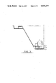
- FIG. 2 is a partial sectional view taken along lines 2--2 of FIG. 1 and part end view;
- FIG. 3 is an enlarged detail of the sectional view shown in the dashed circle of FIG. 2;
- FIG. 4 is a plan view of the frame of the adjustable, removable suspension system
- FIG. 5 is a sectional elevation of the frame of the adjustable, removable suspension system taken along lines 5--5 of FIG. 4;
- FIG. 6 is a sectional elevation of the preferred embodiment of the locking assembly as seen along lines 6--6 of FIG. 4;
- FIG. 7 is a sectional view taken along lines 7--7 of FIG. 4.
- FIG. 8 is an exploded perspective view of the shipping container showing the preferred embodiment of the pallet.
- FIG. 9 is an exploded perspective view of the frame showing details of its mounting to the wall section.
- FIG. 10 is a perspective view of an alternate embodiment of the lock assembly.
- container C includes identical composite wall sections W having seal S interposed therebetween.
- the assembled container C may be mounted on a pallet P for ease of movement and vibration isolation during the shipment process.
- An adjustable, removable suspension system A is mounted in each composite wall section W to suspend a framed work of art F (FIG. 6) therein.
- container C may also include intermediate sections mounted between wall sections W to provide a container C having larger interior dimensions.
- unitary wall section W is preferably vacuum formed of plastic material such as acrylonitrile butadiene styrene, for example, and has a flat segment 10a and a plurality of side segments 10b.
- the flat segment 10a has an inner skin 10c and an outer skin 10d.
- Inner skin 10c is connected around its entire periphery to inner skin 10e of side segments 10b.
- outer skin 10d is connected around its periphery to outer skin 10f of side segments 10b.
- the angle formed between inner skin 10e and inner skin 10c is obtuse.
- composite wall section W defines an enclosure E (FIG. 1) bounded by flat segment 10a on the bottom and outwardly sloping side segments 10b connected to flat segment 10a and gradually sloping upwardly and away from flat segment 10a.
- side segments 10b are formed having a flange 10g at their upper end opposite the end where side segments 10b join flat segment 10a.
- Flange 10g is formed in part by segment 10h which extends from inner skin 10e of side segments 10b to segment 10i. Segment 10i is substantially perpendicular to segment 10h and connects segment 10h to segment 10j.
- segment 10k extends from outer skin 10f of side segments 10b and abuts segment 10j thereby defining an enclosed cavity 10L.
- Cavity 10L is defined by inner skin 10c, inner skin 10e, segment 10h, segment 10i, segment 10k, outer skin 10f, and outer skin 10d.
- Insulator I is housed within cavity 10L.
- Insulator I is preferably a rigid polyurethane foam having a density of thirty kilograms per cubic meter. As best seen in FIG. 2 the thickness of insulator I is not uniform. The portion of insulator I lying between outer skin 10d and inner skin 10c of flat segment 10a is thicker than that between inner skin 10e and outer skin 10f of side segments 10b. For typical applications, insulator I has a maximum layer thickness of approximately sixty millimeters between inner skin 10c and outer skin 10d and up to thirty-six millimeters between outer skin 10f and inner skin 10e. Additionally, as seen in FIG. 1, insulator I may be narrow at the portions underlying corners 10m of flat segment 10a than elsewhere.
- insulator I The portions of maximum thickness of insulator I are those which underly the larger surface areas of wall section W in order to provide environmental protection without reducing the internal dimensions of container C or the ease of stackability. Insulator I also contributes to the structural rigidity of wall section W as well as providing the requisite insulation for container C.
- flange 10g is formed by segments 10h, 10i, 10j, 10n and 10p. Segment 10n is substantially perpendicular to segment 10j and segment 10p is substantially perpendicular to segment 10n. Flange 10g is strengthened by an extension of outer skin 10f which is formed by segment 10k, 10q and 10r. Segment 10q is substantially perpendicular to segment 10k and segment 10r is substantially perpendicular to segment 10q. Segment 10k is attached to segment 10j segment 10n is attached to segment 10q, and segment 10p is attached to segment 10r. Accordingly, segments 10h, 10i, 10j, 10n, and 10p of the flange 10g form a continuous channel 10s which substantially encloses seal S between two identical composite wall sections W.
- shock absorber B is sandwiched between outer skin 10f, segment 10k, segment 10q, segment 10p, segment 10r and outer flange D. As seen in FIG. 2, shock absorber B extends completely around each wall section W and acts as a cushion to isolate wall section W from mechanical shocks imparted to outer flange D or stiffener G connected thereto. Shock absorber B is preferably formed of hard rubber although other suitable resilient material may be used without departing from the spirit of the invention. Shock absorber B is attached to outer flange D and to outer skin 10f, segments 10k, 10q and 10r by a suitable conventional heavy duty contact adhesive. Shock absorber B is defined by surfaces 20a through 20j as shown in FIG. 2.
- Outer flange D abuts shock absorber B at surfaces 20b, 20c, and 20d.
- Outer flange D has a bearing surface 30a which supports stiffener G.
- Outer flange D further includes perpendicular mounting surfaces 30b and 30c (FIG. 1) to which retainer R is secured.
- Outer flange D has a mating surface 30d which, as shown in FIG. 2, abuts a mating surface 30d when one wall section W is mounted to an adjacent wall section W.
- Retainer R includes a plurality of lugs 40a each defining a through hole 40b (see FIG. 1).
- a through bolt 40c secures corresponding lugs 40a on each wall section W thereby allowing flange 10g to substantially enclose seal S. Accordingly, lugs 40a in combination with through bolts 40c maintain container C in a closed, fluid tight condition for transportation.
- Seal S is preferably made of a closed cell neoprene rubber although other suitable, similar materials may be used without departing from the spirit of the invention.
- seal S is substantially enclosed in continuous channel 10s (see FIG. 2) formed in each wall section W.
- Shipping container C also includes stiffener G as shown in FIGS. 1 and 2.
- Stiffener G includes a plurality of tubular members 50a which, as shown in FIG. 2 span over outer skin 10f of side segments 10b as well as outer skin 10d of flat segment 10a. Each end 50b of tubular stiffening members 50a (FIG. 2) is welded to bearing surface 30a. Although members 50a are shown having circular cross-section other cross-sections can be used without departing from the spirit of the invention.
- Stiffener G also includes tubular stiffening members 50c which span outer skin 10f of side segments 10b and outer skin 10d of flat segment 10a. The ends 50d of tubular members 50c are welded to bearing surface 30a of outer flange D.
- Members 50a are disposed substantially perpendicular to members 50c. Members 50a overlap members 50c at several junctures 50e, as shown in FIG. 1.
- a flat 50f on members 50a is designed to overlap a flat 50g on members 50c.
- Flat 50f may be secured to flat 50g in any suitable, conventional manner such as by is welding flat 50f to flat 50g at each point 50e where tubular member 50a overlaps tubular member 50c.
- the net result is a reinforced protective web around wall section W which transmits any mechanical shocks imparted to tubular members 50a or 50c to outer frame D which is insulated from composite wall section W by shock absorber B. It is important, as shown in FIG. 2 that stiffening members 50a and 50c span over outer skin 10f and 10d without making any contact therewith.
- a pallet mounting angle 60a is disposed on one side of wall section W.
- Pallet mounting angle 60a is connected at one end to mounting surface 30b and at the other end to tubular members 50a.
- Pallet mounting angle 60a is formed having large openings 60b to reduce its overall weight without detracting substantially from its strength.
- pallet mounting angle 60a has a mounting surface 60c which is in a plane substantially perpendicular to bearing surface 30a. Openings 60d (FIG. 1) are used to secure pallet P to pallet mounting angle 60a via a through bolt (not shown) inserted through openings 60e defined by pallet P and openings 60d (FIG. 1).
- Pallet P is made of tubular structural members and generally rectangular in overall configuration.
- Pallet P includes tubular bottom section 60f, tubular top section 60g and resilient vibration isolators 60h.
- Isolators 60h are disposed between tubular bottom section 60f and tubular top section 60g at corners 60i, j, k and l.
- Isolators 60h are preferably a layer of hard rubber packing although other resilient materials may be used without departing from the spirit of the invention.
- Openings 60e disposed on tubular top section 60g are spaced to align with openings 60d on each wall section W when such wall sections W are assembled together.
- pallet P not only serves to further retain wall sections W together, but isolates container C from vibrations which routinely occur in normal truck, train and airplane travel. It has been observed that pallet P effectively reduces the shock which would normally have been transmitted to container C when the container was dropped.
- Pallet P may be attached to pallet mounting angles 60a via suitable, conventional quick release type fasteners (not shown) for ready assembly and disassembly.
- gap 60m between tubular top section 60g and tubular bottom section 60f is adapted for use by a forklift truck for easy handling of the assembled shipping container C. It is intended that the shipping container C be transported standing on end, supported and attached to pallet P.
- pallet P is made of tubular structural members and is generally rectangular in overall configuration. Pallet P is divided into two halves 60n and 60p, each half being attached to pallet mounting angle 60a on each wall section W. Each half 60n and 60p is resiliently mounted to mounting surface 60q of pallet mounting angle 60a through the use of shock absorbing material 60r. Suitable mounting brackets 60s are connected to each end of half 60n. Similarly, mounting brackets 60t are connected to half 60p adjacent each of its ends. Shock absorbing materials 60r may be attached to mounting surface 60q of pallet mounting angle 60a and mounting brackets 60s or 60t by using a suitable bonding adhesive (not shown) or a mechanical fitting (not shown). As seen in FIG.
- half 60p has a reduced diameter section 60u disposed at each end.
- the outside diameter of reduced diameter section 60u is slightly smaller than the inside diameter of the tubular member comprising half 60n.
- reduced diameter section 60u extends into half 60n thereby giving pallet P an overall rectangular configuration.
- ends 60v of half 60n may be outwardly flared. Accordingly, when two wall sections are locked together, halves 60n and 60p abut each other with reduced diameter section 60u extending into half 60n.
- Halves 60n and 60p each contain metal feet 60w which raise the container C off the ground and allow easy handling of the assembled container C by a forklift truck or a mobile dolly.
- the shock absorbing material 60r effectively reduces shock and high level vibration which routinely occurs in truck, train and airplane travel. It is intended that container C be transported standing on end supported and attached to pallet P.
- halves 60n and 60p may each be tubular members having square, rectangular or other shapes other than a round cross-section.
- shipping container C includes an adjustable, removable suspension system A flexibly mounted therein.
- the adjustable, removable suspension system A can be installed in each wall section W.
- Support system A includes a frame J, abutment means K (FIGS. 4 and 7), support strap means L, securing strap means M and locking means N (FIG. 6).
- frame J has an essentially rectangular shape which conforms to the periphery of inner skin 10c of flat segment 10a.
- frame J has a tubular cross-section of a square shape although rectangular and round shapes can be used without departing from the spirit of the invention. Accordingly, frame J is defined by surfaces 70a, 70b, 70c and 70d.
- the frame J is secured to wall section W via mounting tabs 70e which are connected to surface 70c at spaced relationships around frame J.
- Each mounting tab 70e defines a mounting opening 70f.
- inner skin 10c of flat segment 10a includes raised sections or mounting bosses 70g. Mounting bosses 70g coincide with the location of mounting tab 70e of frame J.
- a resilient packing layer 70h is attached to mounting boss 70g. Embedded within resilient packing layer 70h is a cylindrical threaded insert 70i. Frame J is secured to wall section W by any suitable, conventional mounting (not shown) such as a screw which is inserted through each opening 70f and threaded into each corresponding cylindrical insert 70i. Resilient packing layer 70h is preferably formed of hard rubber although other resilient materials may be used without departing from the spirit of the invention. Frame J is resiliently mounted to wall section W in that cylindrical insert 70i is free to move within resilient packing layer 70h.
- FIG. 1 An alternative method of mounting frame J to composite wall section W is illustrated in FIG. 1.
- mounting bosses 70g are disposed around the periphery of flat segment 10a.
- a C-shaped resilient packing layer 70h is placed around surfaces 70a, 70c and 70d of frame J, adjacent the location of each mounting boss 70g.
- a retaining clip 70k is secured to mounting surface 70m which forms a part of mounting boss 70g and which is disposed in a plane parallel to surface 70a of frame J. Accordingly, when mounting clip 70k is secured to mounting surface 70m it also contacts resilient packing layer 70h thereby firmly retaining frame J to flat segment 10a yet at the same time allowing frame J to be isolated from mechanical shocks imparted to flat segment 10a due to the operation of resilient packing layer 70h.
- inner skin 10c has a plurality of mounting bosses 70l one of which is displayed in FIG. 9.
- a plurality of annular resilient rings 70m are disposed along frame J such that when frame J is lowered into a wall section W, annular resilient rings 70m are juxtaposed opposed adjacent to mounting bosses 70l.
- Mounting bosses 70n are disposed in innerskin 10e so that they are adjacent to annular resilient rings 70m on frame J when frame J is lowered into wall section W.
- Each mounting boss 70l contains a threaded insert 70p.
- each mounting boss 70n contains a threaded insert 70q.
- Bracket 70r has two parallel segments 70s and 70t.
- Segment 70s has an opening 70u and segment 70t has an opening 70v disposed thereon.
- Bracket 70r is so designed such that when opening 70u is aligned with threaded insert 70q, opening 70v is aligned with threaded insert 70p.
- segment 70tcomes in contact with mounting boss 70l segment 70s simultaneously comes in contact with mounting boss 70n.
- the outside diameter of annular resilient rings 70m is such that when segment 70s is in contact with mounting boss 70n segment 70s is also in contact with annular rings 70m.
- segment 70w which is disposed between segment 70s and 70t on bracket 70r, is in contact with annular resilient ring 70m. Therefore, annular resilient ring 70m is confined on four sides by inner skin 10c, mounting boss 70n segment 70s of bracket 70r and segment 70w of bracket 70r.
- support strap L includes straps 80a and 80b. Straps 80a span frame J and contact surfaces 70a, 70c and 70d of frame J. Straps 80a are preferably approximately fifty millimeters wide and made of black woven nylon, although other materials and widths can be used without departing from the spirit of the invention. Straps 80a are continuous loops and, as seen in FIG. 7, are disposed in a plane parallel to surfaces 70a and 70c. Straps 80b span the opening 70j defined by frame J in a direction perpendicular to straps 80a. Straps 80b are continuous and made of the same material and are the same width as straps 80a although other materials and widths may be used without departing from the spirit of the invention.
- Straps 80b also contact surfaces 70a, 70c and 70d of frame J. As shown in FIG. 4 straps 80a and 80b contact frame J at points removed from where mounting tabs 70e are connected to surface 70c on frame J. Straps 80a and 80b form a web in opening 70j defined by frame J for supporting a framed work of art.
- Abutment K consists of a pair of elongated members 90a and 90b which have an L-shaped cross-section as shown in FIG. 7.
- Elongated member 90a has an abutting surface 90c and an mounting surface 90d.
- elongated member 90b has an abutting surface 90e and a mounting surface 90f.
- abutting surface 90c defines a plurality of mounting slits 90g which are disposed at spaced intervals in alignment with straps 80a. Straps 80a extend through mounting slits 90g thereby preventing lateral movement of elongated member 90a toward elongated member 90b.
- FIG. 7 As seen in FIG. 7,
- a pair of fasteners 90h are disposed in each strap 80a between frame J and elongated member 90a thereby acting as a travel stop and preventing elongated member 90a from moving in a direction perpendicular to its longitudinal axis into contact with frame J.
- a pair of fasteners 90i are disposed in straps 80b between frame J and elongated member 90b thereby acting as a travel stop to elongated member 90b and preventing it from contacting frame J by moving in a direction perpendicular to its longitudinal axis.
- surfaces 90c and 90e of elongated members 90a and 90b, respectively, are substantially lined with a cushion 90j.
- Cushion 90j is preferably made of semi-rigid rubber although other suitable resilient materials may also be used.
- abutting surface 90c with cushioning means 90j attached thereto extends perpendicularly above straps 80a.
- cushion 90k covers the abutting surface 90e of elongated member 90b which extends perpendicularly above straps 80b. Therefore, when a framed work of art is set on straps 80a and 80b, cushions 90j and 90k contact the frame of the work of art.
- elongated members 90a and 90b are disposed in a spaced relation to each other along adjacent sides of frame J and their longitudinal axes form a substantially right angle.
- the elongated members 90a and 90b can pivot 90° so that abutting surfaces 90c and 90e lie against straps 80a and 80b, thus providing a flat surface which enables the wall sections W to be stacked one inside the other without damaging elongated members 90a and 90b.
- Securing web M includes a plurality of straps 100a which are mounted to frame J over straps 80a adjacent surface 70a. Straps 100a each have a free end 100b which can be extended over a framed work of art resting on support strap L and secured to lock N which is slidably mounted to the corresponding strap 80a. Straps 100a may be sewn to straps 80a adjacent surface 70a. Alternatively, suitable conventional fasteners 90h may be employed to secure one end of straps 100a. Straps 100a are preferably made of approximately fifty millimeter wide black woven nylon although other materials and widths may be used without departing from the spirit of the invention.
- Web M also includes straps 100c. Straps 100c have a free end 100d. Accordingly, straps 100c can be extended over a framed work of art and into engagement with a corresponding lock N slidably mounted to the corresponding strap 80b. Straps 100c may each be sewn to straps 80b adjacent surface 70a of frame J. In the alternative, suitable conventional fasteners 90i can be used to secure straps 100c to the corresponding strap 80b.
- each strap 80a has a corresponding strap 100a and each strap 80b has a corresponding strap 100c. Straps 100a and 100c when passed over a framed work of art and engaged in corresponding lock N provide substantial horizontal and vertical support for the framed work of art.
- locks N are slidably mounted to each strap 80a and 80b, adjacent the opposite end of frame J and from where elongated members 90a and 90b are disposed.
- each lock N includes a pivotally mounted locking assembly 110a and a clamp assembly 110b.
- Clamp assembly 110b includes a bottom flat plate member 110c and first plate member 110d and second plate member 110e.
- the juncture of bottom flat plate member 110c and first top plate member 110d defines slot 110f.
- the juncture of bottom flat plate member 110c with second top plate member 110e defines slot 110g.
- Slot 110f is aligned in the same plane with slot 110g thereby allowing strap 80a or strap 80b to pass therethrough depending on the location of clamp assembly 110b.
- first top plate member 110b is disposed in a spaced relationship to second top plate member 100e along bottom flat plate member 110c.
- a pivotally mounted cushion plate 110h is connected to first top plate member 110d.
- Two resilient cushions 110i are secured to the outer edge of the mounted cushion plate 110h.
- Mounted resilient cushion 110i may be a semi-rigid rubber, although other suitable resilient materials may also be used.
- the two mounted resilient cushions 110i are positioned on the clamp assembly 110b so that the cushions lie outside the width dimension of the supporting straps 80a and 80b. This allows cushion plate 110h to lie flat when wall sections W are not in use thus preventing damage to the lock N when wall sections W are stacked one inside the other.
- Resilient cushion 110i is mounted to pivotally mounted cushion plate 110h so that it faces cushion 90j or 90k depending upon whether clamp assembly 110b is slidably mounted to straps 80a or 80b respectively. As seen from FIGS. 4 and 6, a framed work of art abuts cushions 90j and 90k on two sides and resilient cushion 110i on the two opposite sides.
- a removable flexible elongated bracket 110j is connected at one end to pivotally mounted cushion plate 110h. At its free end, flexible elongated bracket 110j is formed having a plurality of securing slots 110k.
- a second resilient cushion 110L is mounted adjacent the free end of flexible elongated bracket 110j to inside surface 110m.
- Web M, or strap 100c as shown in FIG. 6, is passed through slots 110f and 110g to pivotally mounted locking assembly 110a.
- Locking assembly 110a is a clasp lock mechanism of a type well known in the art. Locking assembly 110a serves two functions in that when it is in a perpendicular position to supporting straps 80a or 80b, it secures lock N to said straps.
- Locking assembly 110a also provides a clasp lock mechanism for straps 100a and 100b. As shown in FIG. 6, when locking assembly 110a is moved into a vertical position relative to strap 80a or 80b, it forces first plate member 110d toward blottom flat plate member 110c thereby fixing the position of lock N on strap 80a or 80b. When wall section W is not in use, locking assembly 110a is designed to lie flat against supporting straps 80a or 80b thus allowing wall sections W to be stacked without damaging locking assembly 110a. It is desirable that when removably mounted resilient cushion 110i and second resilient cushion 110L contact the frame of the work of art F (FIG. 6) that the angle between first top plate member 110d and pivotally mounted cushion plate 110h remain acute.
- an alternative embodiment of lock N includes a pivotally mounted locking assembly 110n and a clamp assembly 110p.
- Clamp assembly 110p includes a bottom flat plate member 110q and a movably mounted top plate 110r.
- a slot 110s is defined between bottom flat plate member 110q and movably mounted top plate 110r.
- Clamp plate 110t is disposed in a plane substantially perpendicular to the plane wherein movably mounted top plate 110r and bottom flat plate member 110q are disposed.
- Pivotally mounted locking assembly 110n is disposed adjacent the opposite end of bottom flat plate member 110q and movably mounted top plate 110r, from clamp plate 110t.
- a cushion member 110u is attached to clamp plate 110t by a suitable contact adhesive or other mechanical means.
- Lock N may be suitably disposed on supporting straps 80a and 80b for securing a work of art thereto. Accordingly, straps 80a or 80b extend through slot 110s in order to secure a lock N thereon. Lock N is designed to be moved along strap 80a (FIG. 10) until cushion 110u contacts the work of art (not shown). Locks N are moved along straps 80a and 80b until cushion members 110u secure two adjacent sides of a work of art and force the work of art against cushions 90j and 90k on elongated members 90a and 90b. In order to secure lock N in a fixed position on a strap 80a or 80b, nut 110v is rotated thereby decreasing the height of slot 110s and securing lock N to the strap 80a or 80b.
- cushion members 110u adjacent straps 80a and 80b against the work of art, the work of art is effectively held on straps 80a and 80b with cushion members 110u holding two sides of the work of art and cushions 90j and 90k on elongated members 90a and 90b holding the two opposing sides of the work of art.
- straps 100a or 100c can be passed over the work of art and through pivotally mounting locking assembly 110n thereby securing the work of art between straps 80a and 80b on one side and straps 100a and 100c on the other side.
- a slidably mounted cushion 110w is secured to either strap 100a or 100c for contact with the work of art thereby preventing direct contact between the work of art and straps 100a and 100c.
- a framed work of art F is placed face up on straps 80a and 80b.
- the framed work of art is moved on top of straps 80a and 80b until two of its adjoining sides come in contact with cushions 90j and 90k on elongated members 90a and 90b, respectively.
- straps 100a are passed over the framed work of art F and through slots 110k on the locks N slidably mounted to each strap 80a.
- Straps 100c are also passed over the framed work of art through slots 110k of locks N slidably mounted to each strap 80b.
- straps 100a and 100c are secured in pivotally mounted locking assembly 110a thereby insuring that removably mounted resilient cushion 110i and second resilient cushion 110L are firmly in contact with the framed work of art F.
Abstract
The invention comprises a shipping container with a flexibly mounted adjustable, removable suspension system for transporting works of art of various dimensions. The container includes two identical composite wall sections, each section having a flanged mating surface to form a seal when the container is closed. Each of the wall sections is a composite structure having an inner and an outer skin with an insulation layer in between. Each composite wall section is flexibly mounted to an outer flange to further cushion the assembled shipping container for mechanical shocks. Longitudinal and latitudinal stiffeners are attached on each end to the second flange and span the outer surface of the container. The adjustable, removable suspension system within the container includes a support frame resiliently mounted in each composite wall section. A support strap system in combination with abutment angles support the framed work of art and fix its position relative to the frame. An adjustable locking mechanism is secured to the support strap system when locking clasp is perpendicular to support strap system. Securing straps pass over the frame and extend to adjustable locking mechanisms thereby completely securing the work of art to the frame. The locking mechanisms are cushioned to avoid damaging the work of art.
Description
1. Field of the Invention
The field of the invention relates to reusable containers to transport framed works of art including but not limited to paintings, prints, photographs, and drawings.
2. Description of the Prior Art
In the past, works of art were shipped primarily in wooden crates specifically designed for a particular work or works. Single or multiple cases were used depending upon the size and type of work and frame. The wooden crate was lined with a cushioning and/or insulating material made of various substances depending upon the type of work and preference of the packer. This method of crating had several disadvantages including high material and construction costs; limited durability and useful life; lack of standardization in weight and size of crate; and inconsistent environmental, shock, and vibration protection.
Reusable containers of fiberglass and wood had been developed but still required the preparation and fitting of any internal cushioning by the user. Containers used to ship other products such as highly sensitive equipment had also been adapted to transport three dimensional works of art.
Prior art containers included a rectangular housing having a plurality of guide grooves which were used to secure the frames of the artwork. The container disclosed in U.S. Pat. No. 4,081,119 was typical of such designs. Some designs allowed adjustments in the width of the grooves to accommodate frames of varying thickness as illustrated in U.S. Pat. No. 4,156,498. Other devices for crating paintings such as those shown in U.S. Pat. No. 2,895,599 featured a layered approach with a rigidly mounted support platform which supported the picture frames. In this design, a tightening strap was connected at various points to the mounting platform via selected holes in the mounting platform thereby allowing the crate to accommodate frames of different sizes. The container disclosed in U.S. Pat. No. 3,655,034 employed resilient mounting plates to support urethane foam shock mounts which secured the corners of a picture frame. The shock mounts could be positioned at different points in the mounting plate to accommodate various frame sizes.
Briefly stated, the present invention comprises a shipping container having a unique, flexibly mounted, adjustable, removable suspension system for transporting framed works of art of various dimensions. The container includes two identical composite wall sections, each section having a flanged mating surface to form a seal when the container is closed in the manner set forth in detail below. Each of the wall sections is a composite structure having an inner and an outer skin with an insulation layer in between. Each composite wall section is flexibly mounted to an outer flange to further cushion the assembled shipping container from mechanical shocks. Longitudinal and latitudinal stiffeners are attached each on end to the outer flange and span the outer surface of the container to provide further protection.
The adjustable, removable suspension system includes a support frame resiliently mounted in each composite wall section. A support strap system in combination with abutment angles support the work of art and fix its position relative to the frame. Securing straps pass over the frame and extend to adjustable locking mechanisms thereby completely securing the work of art to the frame. The locking mechanisms are cushioned to avoid damaging the frame of the work of art.
A pallet segment is connected to the outer flange of each composite wall section. The pallet segments are each resiliently mounted to each outer flange to further cushion the assembled container from mechanical shocks. Upon assembling one composite wall section to another, the pallet segments on each wall section interlock with each other thereby forming a unified pallet structure for support of the shipping container. The pallet sections contain shaped metal feet which raise the pallet sections off the ground thereby allowing easy handling of the assembled container by a forklift truck or mobile dolly.
FIG. 1 is an exploded perspective view of the shipping container and one embodiment of pallet;
FIG. 2 is a partial sectional view taken along lines 2--2 of FIG. 1 and part end view;
FIG. 3 is an enlarged detail of the sectional view shown in the dashed circle of FIG. 2;
FIG. 4 is a plan view of the frame of the adjustable, removable suspension system;
FIG. 5 is a sectional elevation of the frame of the adjustable, removable suspension system taken along lines 5--5 of FIG. 4;
FIG. 6 is a sectional elevation of the preferred embodiment of the locking assembly as seen along lines 6--6 of FIG. 4;
FIG. 7 is a sectional view taken along lines 7--7 of FIG. 4.;
FIG. 8 is an exploded perspective view of the shipping container showing the preferred embodiment of the pallet.
FIG. 9 is an exploded perspective view of the frame showing details of its mounting to the wall section.
FIG. 10 is a perspective view of an alternate embodiment of the lock assembly.
Referring now to the drawings, a container according to the present invention is illustrated and designated generally by the letter C. As seen in FIGS. 1 and 2, container C includes identical composite wall sections W having seal S interposed therebetween. The assembled container C may be mounted on a pallet P for ease of movement and vibration isolation during the shipment process. An adjustable, removable suspension system A is mounted in each composite wall section W to suspend a framed work of art F (FIG. 6) therein. Although not specifically illustrated, container C may also include intermediate sections mounted between wall sections W to provide a container C having larger interior dimensions.
Referring now to FIGS. 1 and 2, unitary wall section W is preferably vacuum formed of plastic material such as acrylonitrile butadiene styrene, for example, and has a flat segment 10a and a plurality of side segments 10b. The flat segment 10a has an inner skin 10c and an outer skin 10d. Inner skin 10c is connected around its entire periphery to inner skin 10e of side segments 10b. Similarly, outer skin 10d is connected around its periphery to outer skin 10f of side segments 10b. The angle formed between inner skin 10e and inner skin 10c is obtuse. Accordingly, composite wall section W defines an enclosure E (FIG. 1) bounded by flat segment 10a on the bottom and outwardly sloping side segments 10b connected to flat segment 10a and gradually sloping upwardly and away from flat segment 10a.
As best seen in FIG. 2, side segments 10b are formed having a flange 10g at their upper end opposite the end where side segments 10b join flat segment 10a. Flange 10g is formed in part by segment 10h which extends from inner skin 10e of side segments 10b to segment 10i. Segment 10i is substantially perpendicular to segment 10h and connects segment 10h to segment 10j. At the same time, segment 10k extends from outer skin 10f of side segments 10b and abuts segment 10j thereby defining an enclosed cavity 10L. Cavity 10L is defined by inner skin 10c, inner skin 10e, segment 10h, segment 10i, segment 10k, outer skin 10f, and outer skin 10d.
Insulator I is housed within cavity 10L. Insulator I is preferably a rigid polyurethane foam having a density of thirty kilograms per cubic meter. As best seen in FIG. 2 the thickness of insulator I is not uniform. The portion of insulator I lying between outer skin 10d and inner skin 10c of flat segment 10a is thicker than that between inner skin 10e and outer skin 10f of side segments 10b. For typical applications, insulator I has a maximum layer thickness of approximately sixty millimeters between inner skin 10c and outer skin 10d and up to thirty-six millimeters between outer skin 10f and inner skin 10e. Additionally, as seen in FIG. 1, insulator I may be narrow at the portions underlying corners 10m of flat segment 10a than elsewhere. The portions of maximum thickness of insulator I are those which underly the larger surface areas of wall section W in order to provide environmental protection without reducing the internal dimensions of container C or the ease of stackability. Insulator I also contributes to the structural rigidity of wall section W as well as providing the requisite insulation for container C.
Referring to FIG. 2, flange 10g is formed by segments 10h, 10i, 10j, 10n and 10p. Segment 10n is substantially perpendicular to segment 10j and segment 10p is substantially perpendicular to segment 10n. Flange 10g is strengthened by an extension of outer skin 10f which is formed by segment 10k, 10q and 10r. Segment 10q is substantially perpendicular to segment 10k and segment 10r is substantially perpendicular to segment 10q. Segment 10k is attached to segment 10j segment 10n is attached to segment 10q, and segment 10p is attached to segment 10r. Accordingly, segments 10h, 10i, 10j, 10n, and 10p of the flange 10g form a continuous channel 10s which substantially encloses seal S between two identical composite wall sections W.
As best seen in FIG. 2, shock absorber B is sandwiched between outer skin 10f, segment 10k, segment 10q, segment 10p, segment 10r and outer flange D. As seen in FIG. 2, shock absorber B extends completely around each wall section W and acts as a cushion to isolate wall section W from mechanical shocks imparted to outer flange D or stiffener G connected thereto. Shock absorber B is preferably formed of hard rubber although other suitable resilient material may be used without departing from the spirit of the invention. Shock absorber B is attached to outer flange D and to outer skin 10f, segments 10k, 10q and 10r by a suitable conventional heavy duty contact adhesive. Shock absorber B is defined by surfaces 20a through 20j as shown in FIG. 2.
Outer flange D abuts shock absorber B at surfaces 20b, 20c, and 20d. Outer flange D has a bearing surface 30a which supports stiffener G. Outer flange D further includes perpendicular mounting surfaces 30b and 30c (FIG. 1) to which retainer R is secured. Outer flange D has a mating surface 30d which, as shown in FIG. 2, abuts a mating surface 30d when one wall section W is mounted to an adjacent wall section W.
Retainer R includes a plurality of lugs 40a each defining a through hole 40b (see FIG. 1). When two wall sections W are aligned, as shown in FIG. 2, a through bolt 40c secures corresponding lugs 40a on each wall section W thereby allowing flange 10g to substantially enclose seal S. Accordingly, lugs 40a in combination with through bolts 40c maintain container C in a closed, fluid tight condition for transportation.
Seal S is preferably made of a closed cell neoprene rubber although other suitable, similar materials may be used without departing from the spirit of the invention. When container C is assembled, seal S is substantially enclosed in continuous channel 10s (see FIG. 2) formed in each wall section W.
Shipping container C also includes stiffener G as shown in FIGS. 1 and 2. Stiffener G includes a plurality of tubular members 50a which, as shown in FIG. 2 span over outer skin 10f of side segments 10b as well as outer skin 10d of flat segment 10a. Each end 50b of tubular stiffening members 50a (FIG. 2) is welded to bearing surface 30a. Although members 50a are shown having circular cross-section other cross-sections can be used without departing from the spirit of the invention. Stiffener G also includes tubular stiffening members 50c which span outer skin 10f of side segments 10b and outer skin 10d of flat segment 10a. The ends 50d of tubular members 50c are welded to bearing surface 30a of outer flange D. Members 50a are disposed substantially perpendicular to members 50c. Members 50a overlap members 50c at several junctures 50e, as shown in FIG. 1. A flat 50f on members 50a is designed to overlap a flat 50g on members 50c. Flat 50f may be secured to flat 50g in any suitable, conventional manner such as by is welding flat 50f to flat 50g at each point 50e where tubular member 50a overlaps tubular member 50c. The net result is a reinforced protective web around wall section W which transmits any mechanical shocks imparted to tubular members 50a or 50c to outer frame D which is insulated from composite wall section W by shock absorber B. It is important, as shown in FIG. 2 that stiffening members 50a and 50c span over outer skin 10f and 10d without making any contact therewith.
As shown in FIGS. 1 and 8, a pallet mounting angle 60a is disposed on one side of wall section W. Pallet mounting angle 60a is connected at one end to mounting surface 30b and at the other end to tubular members 50a. Pallet mounting angle 60a is formed having large openings 60b to reduce its overall weight without detracting substantially from its strength. As best seen in FIG. 1, pallet mounting angle 60a has a mounting surface 60c which is in a plane substantially perpendicular to bearing surface 30a. Openings 60d (FIG. 1) are used to secure pallet P to pallet mounting angle 60a via a through bolt (not shown) inserted through openings 60e defined by pallet P and openings 60d (FIG. 1).
One embodiment of pallet P (See FIG. 1) is made of tubular structural members and generally rectangular in overall configuration. Pallet P includes tubular bottom section 60f, tubular top section 60g and resilient vibration isolators 60h. Isolators 60h are disposed between tubular bottom section 60f and tubular top section 60g at corners 60i, j, k and l. Isolators 60h are preferably a layer of hard rubber packing although other resilient materials may be used without departing from the spirit of the invention. Openings 60e disposed on tubular top section 60g are spaced to align with openings 60d on each wall section W when such wall sections W are assembled together. Accordingly, pallet P not only serves to further retain wall sections W together, but isolates container C from vibrations which routinely occur in normal truck, train and airplane travel. It has been observed that pallet P effectively reduces the shock which would normally have been transmitted to container C when the container was dropped. Pallet P may be attached to pallet mounting angles 60a via suitable, conventional quick release type fasteners (not shown) for ready assembly and disassembly. Finally, gap 60m between tubular top section 60g and tubular bottom section 60f is adapted for use by a forklift truck for easy handling of the assembled shipping container C. It is intended that the shipping container C be transported standing on end, supported and attached to pallet P.
In the preferred embodiment (FIG. 8) pallet P is made of tubular structural members and is generally rectangular in overall configuration. Pallet P is divided into two halves 60n and 60p, each half being attached to pallet mounting angle 60a on each wall section W. Each half 60n and 60p is resiliently mounted to mounting surface 60q of pallet mounting angle 60a through the use of shock absorbing material 60r. Suitable mounting brackets 60s are connected to each end of half 60n. Similarly, mounting brackets 60t are connected to half 60p adjacent each of its ends. Shock absorbing materials 60r may be attached to mounting surface 60q of pallet mounting angle 60a and mounting brackets 60s or 60t by using a suitable bonding adhesive (not shown) or a mechanical fitting (not shown). As seen in FIG. 8, half 60p has a reduced diameter section 60u disposed at each end. The outside diameter of reduced diameter section 60u is slightly smaller than the inside diameter of the tubular member comprising half 60n. As a result when two wall sections W are brought together, reduced diameter section 60u extends into half 60n thereby giving pallet P an overall rectangular configuration. It should be noted that to ease the insertion of reduced diameter section 60u into half 60n the ends 60v of half 60n may be outwardly flared. Accordingly, when two wall sections are locked together, halves 60n and 60p abut each other with reduced diameter section 60u extending into half 60n. Halves 60n and 60p each contain metal feet 60w which raise the container C off the ground and allow easy handling of the assembled container C by a forklift truck or a mobile dolly. As with the embodiment shown in FIG. 1, in the preferred embodiment of FIG. 8, the shock absorbing material 60r effectively reduces shock and high level vibration which routinely occurs in truck, train and airplane travel. It is intended that container C be transported standing on end supported and attached to pallet P. It is further understood that halves 60n and 60p may each be tubular members having square, rectangular or other shapes other than a round cross-section.
Referring to FIG. 2, shipping container C includes an adjustable, removable suspension system A flexibly mounted therein. The adjustable, removable suspension system A can be installed in each wall section W. Support system A includes a frame J, abutment means K (FIGS. 4 and 7), support strap means L, securing strap means M and locking means N (FIG. 6).
As best seen in FIGS. 4 and 5, frame J has an essentially rectangular shape which conforms to the periphery of inner skin 10c of flat segment 10a. As shown in FIG. 5, frame J has a tubular cross-section of a square shape although rectangular and round shapes can be used without departing from the spirit of the invention. Accordingly, frame J is defined by surfaces 70a, 70b, 70c and 70d. The frame J is secured to wall section W via mounting tabs 70e which are connected to surface 70c at spaced relationships around frame J. Each mounting tab 70e defines a mounting opening 70f. As best shown in FIG. 3, inner skin 10c of flat segment 10a includes raised sections or mounting bosses 70g. Mounting bosses 70g coincide with the location of mounting tab 70e of frame J. A resilient packing layer 70h is attached to mounting boss 70g. Embedded within resilient packing layer 70h is a cylindrical threaded insert 70i. Frame J is secured to wall section W by any suitable, conventional mounting (not shown) such as a screw which is inserted through each opening 70f and threaded into each corresponding cylindrical insert 70i. Resilient packing layer 70h is preferably formed of hard rubber although other resilient materials may be used without departing from the spirit of the invention. Frame J is resiliently mounted to wall section W in that cylindrical insert 70i is free to move within resilient packing layer 70h.
An alternative method of mounting frame J to composite wall section W is illustrated in FIG. 1. As seen in FIG. 1, mounting bosses 70g are disposed around the periphery of flat segment 10a. A C-shaped resilient packing layer 70h is placed around surfaces 70a, 70c and 70d of frame J, adjacent the location of each mounting boss 70g. A retaining clip 70k is secured to mounting surface 70m which forms a part of mounting boss 70g and which is disposed in a plane parallel to surface 70a of frame J. Accordingly, when mounting clip 70k is secured to mounting surface 70m it also contacts resilient packing layer 70h thereby firmly retaining frame J to flat segment 10a yet at the same time allowing frame J to be isolated from mechanical shocks imparted to flat segment 10a due to the operation of resilient packing layer 70h.
The preferred method of mounting frame J to wall section W is shown in FIG. 9. As seen in FIG. 9, inner skin 10c has a plurality of mounting bosses 70l one of which is displayed in FIG. 9. A plurality of annular resilient rings 70m are disposed along frame J such that when frame J is lowered into a wall section W, annular resilient rings 70m are juxtaposed opposed adjacent to mounting bosses 70l. Mounting bosses 70n are disposed in innerskin 10e so that they are adjacent to annular resilient rings 70m on frame J when frame J is lowered into wall section W. Each mounting boss 70l contains a threaded insert 70p. Similarly, each mounting boss 70n contains a threaded insert 70q. Bracket 70r has two parallel segments 70s and 70t. Segment 70s has an opening 70u and segment 70t has an opening 70v disposed thereon. Bracket 70r is so designed such that when opening 70u is aligned with threaded insert 70q, opening 70v is aligned with threaded insert 70p. Similarly, when segment 70tcomes in contact with mounting boss 70l, segment 70s simultaneously comes in contact with mounting boss 70n. The outside diameter of annular resilient rings 70m is such that when segment 70s is in contact with mounting boss 70n segment 70s is also in contact with annular rings 70m. At the same time, segment 70w which is disposed between segment 70s and 70t on bracket 70r, is in contact with annular resilient ring 70m. Therefore, annular resilient ring 70m is confined on four sides by inner skin 10c, mounting boss 70n segment 70s of bracket 70r and segment 70w of bracket 70r.
As best seen in FIGS. 4 and 7, support strap L includes straps 80a and 80b. Straps 80a span frame J and contact surfaces 70a, 70c and 70d of frame J. Straps 80a are preferably approximately fifty millimeters wide and made of black woven nylon, although other materials and widths can be used without departing from the spirit of the invention. Straps 80a are continuous loops and, as seen in FIG. 7, are disposed in a plane parallel to surfaces 70a and 70c. Straps 80b span the opening 70j defined by frame J in a direction perpendicular to straps 80a. Straps 80b are continuous and made of the same material and are the same width as straps 80a although other materials and widths may be used without departing from the spirit of the invention. Straps 80b also contact surfaces 70a, 70c and 70d of frame J. As shown in FIG. 4 straps 80a and 80b contact frame J at points removed from where mounting tabs 70e are connected to surface 70c on frame J. Straps 80a and 80b form a web in opening 70j defined by frame J for supporting a framed work of art.
Abutment K consists of a pair of elongated members 90a and 90b which have an L-shaped cross-section as shown in FIG. 7. Elongated member 90a has an abutting surface 90c and an mounting surface 90d. Similarly, elongated member 90b has an abutting surface 90e and a mounting surface 90f. As best seen in FIG. 7, abutting surface 90c defines a plurality of mounting slits 90g which are disposed at spaced intervals in alignment with straps 80a. Straps 80a extend through mounting slits 90g thereby preventing lateral movement of elongated member 90a toward elongated member 90b. As seen in FIG. 4, a pair of fasteners 90h are disposed in each strap 80a between frame J and elongated member 90a thereby acting as a travel stop and preventing elongated member 90a from moving in a direction perpendicular to its longitudinal axis into contact with frame J. Similarly, a pair of fasteners 90i are disposed in straps 80b between frame J and elongated member 90b thereby acting as a travel stop to elongated member 90b and preventing it from contacting frame J by moving in a direction perpendicular to its longitudinal axis. As shown in FIGS. 4 and 7, surfaces 90c and 90e of elongated members 90a and 90b, respectively, are substantially lined with a cushion 90j. Cushion 90j is preferably made of semi-rigid rubber although other suitable resilient materials may also be used.
As seen in FIG. 7, abutting surface 90c with cushioning means 90j attached thereto extends perpendicularly above straps 80a. Similarly, cushion 90k covers the abutting surface 90e of elongated member 90b which extends perpendicularly above straps 80b. Therefore, when a framed work of art is set on straps 80a and 80b, cushions 90j and 90k contact the frame of the work of art. As shown in FIG. 4, elongated members 90a and 90b are disposed in a spaced relation to each other along adjacent sides of frame J and their longitudinal axes form a substantially right angle.
It should be noted that when wall sections W are not in use, the elongated members 90a and 90b can pivot 90° so that abutting surfaces 90c and 90e lie against straps 80a and 80b, thus providing a flat surface which enables the wall sections W to be stacked one inside the other without damaging elongated members 90a and 90b.
The framed work of art in place on support strap L and in contact with abutment K, is secured to frame J via securing web M and locks N. Securing web M includes a plurality of straps 100a which are mounted to frame J over straps 80a adjacent surface 70a. Straps 100a each have a free end 100b which can be extended over a framed work of art resting on support strap L and secured to lock N which is slidably mounted to the corresponding strap 80a. Straps 100a may be sewn to straps 80a adjacent surface 70a. Alternatively, suitable conventional fasteners 90h may be employed to secure one end of straps 100a. Straps 100a are preferably made of approximately fifty millimeter wide black woven nylon although other materials and widths may be used without departing from the spirit of the invention.
Web M also includes straps 100c. Straps 100c have a free end 100d. Accordingly, straps 100c can be extended over a framed work of art and into engagement with a corresponding lock N slidably mounted to the corresponding strap 80b. Straps 100c may each be sewn to straps 80b adjacent surface 70a of frame J. In the alternative, suitable conventional fasteners 90i can be used to secure straps 100c to the corresponding strap 80b.
As can readily be seen in FIG. 4, each strap 80a has a corresponding strap 100a and each strap 80b has a corresponding strap 100c. Straps 100a and 100c when passed over a framed work of art and engaged in corresponding lock N provide substantial horizontal and vertical support for the framed work of art.
As shown in FIGS. 4 and 6, locks N are slidably mounted to each strap 80a and 80b, adjacent the opposite end of frame J and from where elongated members 90a and 90b are disposed.
As seen in FIG. 6, the preferred embodiment of each lock N includes a pivotally mounted locking assembly 110a and a clamp assembly 110b. Clamp assembly 110b includes a bottom flat plate member 110c and first plate member 110d and second plate member 110e. The juncture of bottom flat plate member 110c and first top plate member 110d defines slot 110f. The juncture of bottom flat plate member 110c with second top plate member 110e defines slot 110g. Slot 110f is aligned in the same plane with slot 110g thereby allowing strap 80a or strap 80b to pass therethrough depending on the location of clamp assembly 110b. As seen in FIG. 6, first top plate member 110b is disposed in a spaced relationship to second top plate member 100e along bottom flat plate member 110c.
A pivotally mounted cushion plate 110h is connected to first top plate member 110d. Two resilient cushions 110i are secured to the outer edge of the mounted cushion plate 110h. Mounted resilient cushion 110i may be a semi-rigid rubber, although other suitable resilient materials may also be used. The two mounted resilient cushions 110i are positioned on the clamp assembly 110b so that the cushions lie outside the width dimension of the supporting straps 80a and 80b. This allows cushion plate 110h to lie flat when wall sections W are not in use thus preventing damage to the lock N when wall sections W are stacked one inside the other. Resilient cushion 110i is mounted to pivotally mounted cushion plate 110h so that it faces cushion 90j or 90k depending upon whether clamp assembly 110b is slidably mounted to straps 80a or 80b respectively. As seen from FIGS. 4 and 6, a framed work of art abuts cushions 90j and 90k on two sides and resilient cushion 110i on the two opposite sides.
A removable flexible elongated bracket 110j is connected at one end to pivotally mounted cushion plate 110h. At its free end, flexible elongated bracket 110j is formed having a plurality of securing slots 110k. A second resilient cushion 110L is mounted adjacent the free end of flexible elongated bracket 110j to inside surface 110m. Web M, or strap 100c as shown in FIG. 6, is passed through slots 110f and 110g to pivotally mounted locking assembly 110a. Locking assembly 110a is a clasp lock mechanism of a type well known in the art. Locking assembly 110a serves two functions in that when it is in a perpendicular position to supporting straps 80a or 80b, it secures lock N to said straps. Locking assembly 110a also provides a clasp lock mechanism for straps 100a and 100b. As shown in FIG. 6, when locking assembly 110a is moved into a vertical position relative to strap 80a or 80b, it forces first plate member 110d toward blottom flat plate member 110c thereby fixing the position of lock N on strap 80a or 80b. When wall section W is not in use, locking assembly 110a is designed to lie flat against supporting straps 80a or 80b thus allowing wall sections W to be stacked without damaging locking assembly 110a. It is desirable that when removably mounted resilient cushion 110i and second resilient cushion 110L contact the frame of the work of art F (FIG. 6) that the angle between first top plate member 110d and pivotally mounted cushion plate 110h remain acute.
As seen in FIG. 10, an alternative embodiment of lock N, includes a pivotally mounted locking assembly 110n and a clamp assembly 110p. Clamp assembly 110p includes a bottom flat plate member 110q and a movably mounted top plate 110r. A slot 110s is defined between bottom flat plate member 110q and movably mounted top plate 110r. Clamp plate 110t is disposed in a plane substantially perpendicular to the plane wherein movably mounted top plate 110r and bottom flat plate member 110q are disposed. Pivotally mounted locking assembly 110n is disposed adjacent the opposite end of bottom flat plate member 110q and movably mounted top plate 110r, from clamp plate 110t. A cushion member 110u is attached to clamp plate 110t by a suitable contact adhesive or other mechanical means. Lock N may be suitably disposed on supporting straps 80a and 80b for securing a work of art thereto. Accordingly, straps 80a or 80b extend through slot 110s in order to secure a lock N thereon. Lock N is designed to be moved along strap 80a (FIG. 10) until cushion 110u contacts the work of art (not shown). Locks N are moved along straps 80a and 80b until cushion members 110u secure two adjacent sides of a work of art and force the work of art against cushions 90j and 90k on elongated members 90a and 90b. In order to secure lock N in a fixed position on a strap 80a or 80b, nut 110v is rotated thereby decreasing the height of slot 110s and securing lock N to the strap 80a or 80b. With cushion members 110u adjacent straps 80a and 80b, against the work of art, the work of art is effectively held on straps 80a and 80b with cushion members 110u holding two sides of the work of art and cushions 90j and 90k on elongated members 90a and 90b holding the two opposing sides of the work of art. To further secure the work of art to frame J, straps 100a or 100c can be passed over the work of art and through pivotally mounting locking assembly 110n thereby securing the work of art between straps 80a and 80b on one side and straps 100a and 100c on the other side. A slidably mounted cushion 110w is secured to either strap 100a or 100c for contact with the work of art thereby preventing direct contact between the work of art and straps 100a and 100c.
In use, a framed work of art F is placed face up on straps 80a and 80b. The framed work of art is moved on top of straps 80a and 80b until two of its adjoining sides come in contact with cushions 90j and 90k on elongated members 90a and 90b, respectively. Thereafter, straps 100a are passed over the framed work of art F and through slots 110k on the locks N slidably mounted to each strap 80a. Straps 100c are also passed over the framed work of art through slots 110k of locks N slidably mounted to each strap 80b. Finally, straps 100a and 100c are secured in pivotally mounted locking assembly 110a thereby insuring that removably mounted resilient cushion 110i and second resilient cushion 110L are firmly in contact with the framed work of art F. Once the framed work of art is secured in the adjustable, removable suspension system A, wall sections W are brought together and secured via lugs 40a and through bolts 40c. Finally, pallet P is secured to the respective pallet mounting angle 60a on each wall section W. The framed work of art F is then ready to be shipped.
The foregoing disclosure and description of the invention are illustrative and explanatory thereof, and various changes in the size, shape and materials, as well as in the details of the illustrated construction may be made without departing from the spirit of the invention.
Claims (32)
1. A shipping container for transporting works of art comprising:
a pair of composite wall sections each further comprising:
a substantially flat segment;
a plurality of side sections adjoining said flat segment thereby defining an enclosure;
said flat and side segments having an inner and outer skin and an insulation means disposed between said inner and outer skin for protection of the work of art from external environmental conditions by maintaining a relatively constant humidity between said composite wall sections, said side segments having a first flange formed about their periphery to provide a seal between said wall sections when said container is closed;
retaining means for securing one composite wall section to another;
sealing means disposed between said first flange of each of said composite wall sections for sealing therebetween thereby preventing fluids from entering the container;
pallet means mounted to the exterior of said composite wall sections for supporting and cushioning said composite wall sections from shocks during transit; and
wherein each of said composite wall sections further comprise a pallet mounting bracket for mounting said pallet means to each of said composite wall sections when said first flanges on said wall sections are aligned and abutting.
2. The shipping container of claim 1 wherein said pallet means further comprises:
a rigid elongated top section adapted to be mounted to said pallet mounting brackets of said composite wall sections;
a rigid elongated bottom section; and
resilient shock and vibration cushioning means for connecting said elongated top and bottom sections of said pallet in a spaced relation to each other, to reduce shocks and vibration transmitted to the container during shipment and to facilitate handling of the container by machine.
3. The shipping container of claim 1 wherein said pallet means further comprises:
an elongated first section resiliently mounted to said bracket on one of said composite wall sections and having a projection extending longitudinally at each end thereof; and
a second elongated section resiliently mounted to said bracket on the other said composite wall section and having an opening in each end;
whereupon when said composite wall sections are assembled together said projections of said first section extend into said openings in said ends of said second section to form a supporting structure to cushion said composite wall sections from shocks.
4. The shipping container of claim 3 further including:
a plurality of feet on said first and second sections thereby elevating said first and second sections from a support surface.
5. The shipping container of claim 1 further including:
an adjustable, removable suspension system for supporting works of art connected to each of said composite wall sections.
6. A shipping container for transporting works of art comprising:
a pair of composite wall sections each further comprising:
a substantially flat segment;
a plurality of side sections adjoining said flat segment thereby defining an enclosure;
said flat and side segments having an inner and outer skin and an insulation means disposed between said inner and outer skin for protection of the work of art from external environmental conditions, said side segments having a first flange formed about their periphery to provide a seal between said wall sections when said container is closed;
retaining means for securing one composite wall section to another; and
sealing means disposed between said first flange of each of said composite wall sections for sealing therebetween thereby preventing fluids from entering the container;
an ajustable, removable suspension system for supporting works of art connected to each of said composite wall sections;
said ajustable, removable suspension system further comprises:
a support frame resiliently mounted to the periphery of an inner wall of said composite wall section and formed having a central opening therethrough;
support strap means secured to said frame and spanning said central opening for supporting a work of art;
abutment means mounted to said support strap means for positioning the work of art on said support strap means;
securing web means attached to said first strap means for securing a work of art against said support strap means and said abutment means; and
locking means for adjustably connecting said support and securing strap means thereby allowing works of art of different dimensions to be secured therebetween and against said abutment means.
7. The shipping container of claim 6 wherein said supporting strap means of the adjustable, removable suspension system further comprises:
a first strap extending across said opening in said frame; and
a second strap extending across said opening in said frame at substantially right angle to said first strap.
8. The shipping container of claim 7 wherein said abutment means further comprises:
a first elongated member having an L-shaped cross-section and wherein said first elongated member is formed having a first mounting surface disposed in a plane substantially parallel to said first strap; a first abutting surface extending substantially perpendicularly beyond the plane of the opening in said support frame, and a first mounting slit therethrough; and
wherein said first strap extends through said first mounting slit to retain said first elongated member in a spaced relationship to said frame in a direction parallel the longitudinal axis of said first elongated member.
9. The shipping container of claim 8 wherein said abutment means further comprises:
a first travel stop means on said first strap between said first elongated member and said support frame for preventing movement of said first elongated member into contact with said support frame.
10. The shipping container of claim 9 wherein said abutment means further comprises
a second elongated member having an L-shaped cross-section and wherein said second elongated member is formed having a second mounting surface disposed in a plane substantially parallel to said second strap; a second abutting surface extending substantially perpendicularly beyond the plane of the opening in said support frame and having a second mounting slit therethrough;
whereby said second strap extends through said second mounting slit to retain said second elongated member in a spaced relationship to said support frame in a direction parallel to the longitudinal axis of said second elongated member.
11. The shipping container of claim 10 wherein said abutment means further comprises:
a second travel stop means on said second strap between said second elongated member and said support frame for preventing movement of said second elongated member into contact with said support frame.
12. The shipping container of claim 11 wherein
said first and second elongated members are disposed parallel to and adjacent to two connected sides of said support frame with their longitudinal axes intersecting at a substantially right angle.
13. The shipping container of claim 8 wherein:
said first and second abutting surfaces each further comprise:
cushioning means for receiving the work of art and protecting the work of art from direct contact with said first and second abutting surfaces.
14. The shipping container of claim 13 wherein:
said first and second elongated members are pivotally mounted to said support strap means thereby allowing said first and second abutting surfaces to be aligned with said support strap means to allow nesting of one of said composite wall sections in another composite wall section without damaging said first and second elongated members.
15. The shipping container of claim 14 wherein
said support frame is formed having a tubular cross-section and further comprising:
a plurality of resilient members at spaced intervals on said support frame; and
retaining clips in contact with said resilient members on said support frame for resiliently mounting said support frame to said wall sections.
16. The shipping container of claim 7 wherein said securing web means further comprises:
a third strap secured at one end to said first strap adjacent said support frame; and
a fourth strap secured at one end to said second strap adjacent said support frame; and
wherein said third and fourth straps secure the work of art to said first and second straps and against said first and second elongated members.
17. The shipping container of claim 16 wherein said locking means further comprises:
a first clamp means for securing said third strap over the work of art, said first clamp means being slidably mounted to said first strap; and
a second clamp means for securing said fourth strap over the work of art, said second clamp means being slidably mounted to said second strap.
18. The shipping container of claim 17 wherein said first and second clamp means each comprise:
a bottom plate member;
a first top plate member lying in a plane substantially parallel to said bottom plate and connected to said bottom plate member so as to define a first slot therebetween;
a second top plate member lying in a plane substantially parallel to said bottom plate and connected to said bottom plate member so as to define a second slot therebetween;
said second top plate member being in a spaced relation to said first top plate member and wherein said first slot is disposed in the same plane as said second slot;
whereby said support strap means is threaded through said first and second slots to slidably mount said first and second means to said support strap means.
19. The shipping container of claim 18 wherein said first and second clamp means each further comprise:
a pivotally mounted cushion plate connected to the end of said first top plate member adjacent said second top plate member;
a first resilient cushion connected to said pivotally mounted cushion plate;
a flexible elongated bracket connected at one end to said pivotally mounted cushion plate and formed having a plurality of securing slots adjacent its opposite free end; and
a second resilient cushion connected adjacent the free end of said flexible elongated bracket.
20. The shipping container of claim 19 wherein said locking means further comprises:
a pivotally mounted locking assembly connected to the end of said first top plate member opposite said pivotally mounted cushion plate, and wherein said securing web means is adapted to pass over the work of art positioned on said support strap means, through said securing slots of said flexible elongated bracket and to said pivotally mounted locking assembly thereby forcing said first resilient cushion and said second resilient cushion into contact with the work of art to secure the work of art in the opening defined by said support frame.
21. The shipping container of claim 14 wherein:
the angle formed by said pivotally mounted cushion plate and said first top plate member remains acute after said first resilient member is secured against the work of art.
22. The shipping container of claim 17 wherein said first and second clamps each comprise:
a bottom plate member;
a top plate movably mounted to said bottom plate member defining a slot therebetween, said support strap means extending through said slot;
tightening means whith said top plate for moving said top plate toward said bottom plate for secruing said first and second clamps to said support strap means.
23. The shipping container of claim 22 further including:
a cushion plate mounted to one end of said bottom plate member;
a first resilient cushion mounted to said cushion plate said cushion selectively movable into contact with a work of art adjacent to said support strap means; and
a pivotally mounted locking assembly connected to said bottom plate member at the opposite end of said bottom plate member from said cushion plate;
a slidably mounted second resilient cushion mounted to said securing web means;
whereupon said securing web means is adapted to pass over the work of art positioned on said support strap means, with said second resilient cushion in contact with the work of art, and through said locking assembly to secure the work of art in the opening defined by said support frame.
24. The shipping container of claim 15 wherein said securing web means further comprises:
a third strap secured at one end to said first strap adjacent said support frame; and
a fourth strap secured at one end to said second strap adjacent said support frame; and
wherein said third and fourth straps secure the work of art to said first and second straps and against said first and second elongated members.
25. The shipping container of claim 24 wherein said locking means further comprises:
a first clamp means for securing said third strap over the work of art, said first clamp means being slidably mounted to said first strap; and
a second clamp means for securing said fourth strap over the work of art, said second clamp means being slidably mounted to said second strap.
26. The shipping container of claim 25 wherein said first and second clamp means each comprise:
a bottom plate member;
a first top plate member lying in a plane substantially parallel to said bottom plate and connected to said bottom plate member so as to define a first slot therebetween;
a second top plate member lying in a plane substantially parallel to said bottom plate and connected to said bottom plate member so as to define a second slot therebetween;
said second top plate member being in a spaced relation to said first top plate member and wherein said first slot is disposed in the same plane as said second slot;
whereby said support strap means is threaded through said first and second slots to slidably mount said first and second means to said support strap means.
27. The shipping container of claim 26 wherein said first and second clamp means each further comprise:
a pivotally mounted cushion plate connected to the end of said first top plate member adjacent said second top plate member;
a first resilient cushion connected to said pivotally mounted cushion plate;
a flexible elongated bracket connected at one end to said pivotally mounted cushion plate and formed having a plurality of securing slots adjacent its opposite free end; and
a second resilient cushion connected adjacent the free end of said flexible elongated bracket.
28. The shipping container of claim 27 wherein said locking means further comprises:
a pivotally mounted locking assembly connected to the end of said first top plate member opposite said pivotally mounted cushion plate, and wherein said securing web means is adapted to pass over the work of art positioned on said support strap means, through said securing slots of said flexible elongated bracket and to said pivotally mounted locking assembly thereby forcing said first resilient cushion and said second resilient cushion into contact with the work of art to secure the work of art in the opening defined by said support frame.
29. The shipping container of claim 28 where:
the angle formed by said pivotally mounted cushion plate and said first top plate member remains acute after said first resilient member is secured against the work of art.
30. The shipping container of claim 29 wherein said first and second clamps each comprise:
a bottom plate member;
a top plate movably mounted to said bottom plate member defining a slot therebetween, said support strap means extending through said slot;
tightening means with said top plate for moving said top plate toward said bottom plate for securing said first and second clamps to said support strap means.
31. The shipping container of claim 30 further including:
a cushion plate mounted to one end of said bottom plate member;
a first resilient cushion mounted to said cushion plate said cushion selectively movable into contact with a work of art adjacent to said support strap means; and
a pivotally mounted locking assembly connected to said bottom plate member at the opposite end of said bottom plate member from said cushion plate;
a slidably mounted second resilient cushion mounted to said securing web means;
whereupon said securing web means is adapted to pass over the work of art positioned on said support strap means, with said second resilient cushion in contact with the work of art, and through said locking assembly to secure the work of art in the opening defined by said support frame.
32. A shipping container for transporting works of art comprising:
a pair of composite wall sections each further comprising:
a substantially flat segment;
a plurality of side sections adjoining said flat segment thereby defining an enclosure;
said flat and side segments having an inner and outer skin and an insulation means disposed between said inner and outer skin for protection of the work of art from external environmental conditions by maintaining a relatively constant humidity between said composite wall sections, said side segments having a first flange formed about their periphery to provide a seal between said wall sections when said container is closed;
retaining means for securing one composite wall section to another; and
sealing means disposed between said first flange of each of said composite wall sections for sealing therebetween thereby preventing fluids from entering the container;
an adjustable, removable suspension system for supporting works of art connected to each of said composite wall sections.
Applications Claiming Priority (2)
| Application Number | Priority Date | Filing Date | Title |
|---|---|---|---|
| GB8414484 | 1984-06-06 | ||
| GB08414484A GB2159797B (en) | 1984-06-06 | 1984-06-06 | An adjustable suspension system and shipping container for works of art |
Publications (1)
| Publication Number | Publication Date |
|---|---|
| US4664254A true US4664254A (en) | 1987-05-12 |
Family
ID=10562040
Family Applications (1)
| Application Number | Title | Priority Date | Filing Date |
|---|---|---|---|
| US06/740,868 Expired - Fee Related US4664254A (en) | 1984-06-06 | 1985-06-03 | Shipping container for works of art |
Country Status (2)
| Country | Link |
|---|---|
| US (1) | US4664254A (en) |
| GB (1) | GB2159797B (en) |
Cited By (43)
| Publication number | Priority date | Publication date | Assignee | Title |
|---|---|---|---|---|
| US4925045A (en) * | 1989-11-01 | 1990-05-15 | Logsdon Foundation | Tub boxes |
| US5111362A (en) * | 1990-09-18 | 1992-05-05 | Intel Corporation | Enclosure assembly with two identical covers having modifiable supports for asymmetrically housing a printed circuit board or the like |
| US5259523A (en) * | 1992-09-15 | 1993-11-09 | Scherb David A | Modular art work carrier |
| US5285902A (en) * | 1991-06-14 | 1994-02-15 | Ana Tabuenca Garcia | Packaging system for paintings, other works of art and the like |
| DE4318045A1 (en) * | 1993-05-29 | 1994-12-01 | Hasenkamp Int Transporte | Transport holder for picture frames or the like |
| US5524754A (en) * | 1994-05-19 | 1996-06-11 | Port, Incorporated | Carrying case for notebook computer |
| US5655662A (en) * | 1994-10-18 | 1997-08-12 | Garcia; Ana Tabuenca | Universal system for packaging three-dimensional objects |
| US5803258A (en) * | 1997-02-12 | 1998-09-08 | Archival Matters, Inc. | System for holding fragile items |
| US5827385A (en) * | 1994-07-15 | 1998-10-27 | Vacupanel, Inc. | Method of producing an evacuated insulated container |
| USD423929S (en) * | 1998-10-21 | 2000-05-02 | Tosoh Smd, Inc. | Protective package |
| US6343707B2 (en) * | 2000-04-20 | 2002-02-05 | Tsung-Kan Cheng | Memory card casing |
| US20020046520A1 (en) * | 2000-10-06 | 2002-04-25 | Ani Gonzalez-Rivera | Fragile article transportation, display and storage system |
| DE10059037A1 (en) * | 2000-11-28 | 2002-05-29 | Joerg Fasbender | Continuously adjustable transport container for paintings etc. has internal comb-like meshing walls sliding along guides and fastened to one fixed container wall |
| US20030094825A1 (en) * | 2000-06-22 | 2003-05-22 | Herve Poux | Device for protecting a painter's canvas in particular during its transport |
| EP1364889A1 (en) * | 2002-05-24 | 2003-11-26 | Zürcher Freilager AG | Transport unit for objects of art |
| US20040031715A1 (en) * | 2001-11-02 | 2004-02-19 | Kuldip Randhawa | Package restraint system |
| US20040074902A1 (en) * | 2002-10-22 | 2004-04-22 | Hayes Thomas J. | Containers and container assemblies with releasable locking feature |
| US20050189350A1 (en) * | 2002-10-22 | 2005-09-01 | Pactiv Corporation | Container assemblies with releasable locking feature |
| US20060000076A1 (en) * | 2002-10-22 | 2006-01-05 | Hayes Thomas J | Method of using a container assembly |
| US20060157372A1 (en) * | 2005-01-14 | 2006-07-20 | Versacrate Corporation | Shipping device |
| US20060159807A1 (en) * | 2002-10-22 | 2006-07-20 | Hayes Thomas J | Container assemblies with releasable locking feature |
| US20070023428A1 (en) * | 2005-07-26 | 2007-02-01 | Pactiv Corporation | Container assemblies with releasable locking feature |
| US20070172554A1 (en) * | 2005-09-30 | 2007-07-26 | Pactiv Corporation | Modular container assembly and merchandizing container display |
| US7422112B1 (en) | 2005-08-15 | 2008-09-09 | Museum Quality Shipping, Llc | Protective containment of valued articles |
| US20090065514A1 (en) * | 2007-09-06 | 2009-03-12 | Terry Vovan | Invertible tray |
| US20090229936A1 (en) * | 2008-03-13 | 2009-09-17 | Targus Group International, Inc. | Portable computer case |
| US7686169B1 (en) | 2005-08-15 | 2010-03-30 | Museum Quality Shipping, Llc | Protective containment of valued articles |
| US20130233757A1 (en) * | 2010-07-01 | 2013-09-12 | Daniela Fileni | Cradle for transport and shipment without danger of breaking brittle and precious objects |
| US8763795B1 (en) | 2013-01-23 | 2014-07-01 | Targus Group International, Inc. | Dual support flap case |
| US9403623B2 (en) | 2013-07-05 | 2016-08-02 | Craig L. Aaland | Adjustable, reusable packing crate |
| WO2017069618A1 (en) | 2015-10-19 | 2017-04-27 | Turtle B.V. | A shipping container for transporting works of art |
| US9675148B2 (en) | 2015-03-18 | 2017-06-13 | Targus International Llc | Extendable, universal case for portable electronic devices |
| USD818319S1 (en) | 2016-08-17 | 2018-05-22 | Reynolds Consumer Products LLC | Plate |
| USD823644S1 (en) | 2016-06-06 | 2018-07-24 | Reynolds Consumer Products LLC | Plate |
| USD823645S1 (en) | 2016-06-06 | 2018-07-24 | Reynolds Consumer Products LLC | Plate |
| US10131370B1 (en) * | 2017-01-31 | 2018-11-20 | Glenn W. Harte | Cart for protected transport of vulnerable artwork and method |
| US10334936B2 (en) | 2009-05-06 | 2019-07-02 | Tumi, Inc. | Checkpoint-friendly backpack |
| WO2020005314A1 (en) * | 2018-06-29 | 2020-01-02 | Dennis Fisher | System and method for the storage and protection of priceless works of art |
| US10723539B2 (en) | 2017-03-28 | 2020-07-28 | Turtle B.V. | Insulated shipping container for works of art |
| DE102019110894A1 (en) * | 2019-04-26 | 2020-10-29 | Steven Kern | Transport box for two-dimensional works of art |
| CN112707021A (en) * | 2021-02-19 | 2021-04-27 | 长沙理工大学 | Protective device for industrial art |
| USD936969S1 (en) | 2020-01-31 | 2021-11-30 | Targus International Llc | Pocket for portable electronic device |
| US11470986B2 (en) * | 2019-01-18 | 2022-10-18 | Jerome S. Feig | Anoxic microclimate storage and display device |
Families Citing this family (1)
| Publication number | Priority date | Publication date | Assignee | Title |
|---|---|---|---|---|
| ES2040618B1 (en) * | 1991-06-14 | 1994-05-16 | Garcia Ana Tabuenca | PACKING SYSTEM FOR PICTURES, OTHER ARTISTIC AND SIMILAR WORKS. |
Citations (19)
| Publication number | Priority date | Publication date | Assignee | Title |
|---|---|---|---|---|
| GB406357A (en) * | 1932-08-25 | 1934-02-26 | Alexander Henry Barnes | Improvements in, or relating to, cardboard boxes |
| US2110947A (en) * | 1937-03-11 | 1938-03-15 | Frederick C Bartels | Paper retainer |
| US2895599A (en) * | 1958-03-28 | 1959-07-21 | Harold W Moyer | Device for crating paintings and the like |
| US2939603A (en) * | 1956-11-15 | 1960-06-07 | Various Assignees | Plastic containers |
| US2950001A (en) * | 1957-05-13 | 1960-08-23 | Edward P Bucko | Crate for shipping glass |
| US2976985A (en) * | 1960-08-11 | 1961-03-28 | Philip J Kraus | Carrying case for wet paintings |
| CA689934A (en) * | 1964-07-07 | W. Lawson Frank | Container | |
| FR1519008A (en) * | 1967-02-28 | 1968-03-29 | Improvements to easels | |
| US3640420A (en) * | 1969-12-19 | 1972-02-08 | Edward Kelley Corp | Cooler chest |
| US3653707A (en) * | 1969-10-03 | 1972-04-04 | Libbey Owens Ford Co | Flat glass shipping case |
| US3655034A (en) * | 1970-02-24 | 1972-04-11 | Polycon Ind Inc | Shipping container |
| DE2326295A1 (en) * | 1972-05-24 | 1973-11-29 | Kenzo Dr Ing Takahashi | GOODS TRANSPORT CONTAINER |
| US3927764A (en) * | 1974-07-30 | 1975-12-23 | Murray J Fox | Stacking collar for warehousing and transporting sheet material |
| US4013170A (en) * | 1975-01-18 | 1977-03-22 | Dornier System Gmbh | Shipping container |
| US4081119A (en) * | 1976-07-13 | 1978-03-28 | Messmore Robert L | Carrying case |
| US4156498A (en) * | 1978-03-09 | 1979-05-29 | Miller Martin S | Carrier for framed art works |
| GB2106249A (en) * | 1981-07-30 | 1983-04-07 | Becton Dickinson Co | Protective instrument mounting for carrying case |
| US4446968A (en) * | 1982-09-17 | 1984-05-08 | Bremer Mary E | Carry cover art oil canvas |
| US4476988A (en) * | 1979-09-20 | 1984-10-16 | Wes Ltd. | Storage and transport containers |
-
1984
- 1984-06-06 GB GB08414484A patent/GB2159797B/en not_active Expired
-
1985
- 1985-06-03 US US06/740,868 patent/US4664254A/en not_active Expired - Fee Related
Patent Citations (19)
| Publication number | Priority date | Publication date | Assignee | Title |
|---|---|---|---|---|
| CA689934A (en) * | 1964-07-07 | W. Lawson Frank | Container | |
| GB406357A (en) * | 1932-08-25 | 1934-02-26 | Alexander Henry Barnes | Improvements in, or relating to, cardboard boxes |
| US2110947A (en) * | 1937-03-11 | 1938-03-15 | Frederick C Bartels | Paper retainer |
| US2939603A (en) * | 1956-11-15 | 1960-06-07 | Various Assignees | Plastic containers |
| US2950001A (en) * | 1957-05-13 | 1960-08-23 | Edward P Bucko | Crate for shipping glass |
| US2895599A (en) * | 1958-03-28 | 1959-07-21 | Harold W Moyer | Device for crating paintings and the like |
| US2976985A (en) * | 1960-08-11 | 1961-03-28 | Philip J Kraus | Carrying case for wet paintings |
| FR1519008A (en) * | 1967-02-28 | 1968-03-29 | Improvements to easels | |
| US3653707A (en) * | 1969-10-03 | 1972-04-04 | Libbey Owens Ford Co | Flat glass shipping case |
| US3640420A (en) * | 1969-12-19 | 1972-02-08 | Edward Kelley Corp | Cooler chest |
| US3655034A (en) * | 1970-02-24 | 1972-04-11 | Polycon Ind Inc | Shipping container |
| DE2326295A1 (en) * | 1972-05-24 | 1973-11-29 | Kenzo Dr Ing Takahashi | GOODS TRANSPORT CONTAINER |
| US3927764A (en) * | 1974-07-30 | 1975-12-23 | Murray J Fox | Stacking collar for warehousing and transporting sheet material |
| US4013170A (en) * | 1975-01-18 | 1977-03-22 | Dornier System Gmbh | Shipping container |
| US4081119A (en) * | 1976-07-13 | 1978-03-28 | Messmore Robert L | Carrying case |
| US4156498A (en) * | 1978-03-09 | 1979-05-29 | Miller Martin S | Carrier for framed art works |
| US4476988A (en) * | 1979-09-20 | 1984-10-16 | Wes Ltd. | Storage and transport containers |
| GB2106249A (en) * | 1981-07-30 | 1983-04-07 | Becton Dickinson Co | Protective instrument mounting for carrying case |
| US4446968A (en) * | 1982-09-17 | 1984-05-08 | Bremer Mary E | Carry cover art oil canvas |
Non-Patent Citations (4)
| Title |
|---|
| Fabwell Sales Brochure. * |
| Hardigg Sales Brochures. * |
| Packing: A Case Study, by Sarah Staniforth, p. 53 62. * |
| Packing: A Case Study, by Sarah Staniforth, p. 53-62. |
Cited By (61)
| Publication number | Priority date | Publication date | Assignee | Title |
|---|---|---|---|---|
| US4925045A (en) * | 1989-11-01 | 1990-05-15 | Logsdon Foundation | Tub boxes |
| US5111362A (en) * | 1990-09-18 | 1992-05-05 | Intel Corporation | Enclosure assembly with two identical covers having modifiable supports for asymmetrically housing a printed circuit board or the like |
| US5285902A (en) * | 1991-06-14 | 1994-02-15 | Ana Tabuenca Garcia | Packaging system for paintings, other works of art and the like |
| US5259523A (en) * | 1992-09-15 | 1993-11-09 | Scherb David A | Modular art work carrier |
| EP0636546A3 (en) * | 1993-05-29 | 1995-02-15 | Hasenkamp Int Transporte | |
| EP0636546A2 (en) * | 1993-05-29 | 1995-02-01 | HASENKAMP INTERNATIONALE TRANSPORTE GmbH & Co. KG | Transport-fixture for picture frames or something like that |
| US5518118A (en) * | 1993-05-29 | 1996-05-21 | Hasenkamp Internationale Transport Gmbh & Co. Kg | Transporting holding device for picture frames or the like |
| US5595301A (en) * | 1993-05-29 | 1997-01-21 | Hasenkamp Internationale Transport Gmbh & Co. Kg | Transporting holding device for picture frames or the like |
| EP0842866A1 (en) * | 1993-05-29 | 1998-05-20 | Hasenkamp Internationale Transporte GmbH & Co. KG | Transport fixing device for picture frames or similar in a container |
| DE4318045A1 (en) * | 1993-05-29 | 1994-12-01 | Hasenkamp Int Transporte | Transport holder for picture frames or the like |
| US5524754A (en) * | 1994-05-19 | 1996-06-11 | Port, Incorporated | Carrying case for notebook computer |
| US5827385A (en) * | 1994-07-15 | 1998-10-27 | Vacupanel, Inc. | Method of producing an evacuated insulated container |
| US5655662A (en) * | 1994-10-18 | 1997-08-12 | Garcia; Ana Tabuenca | Universal system for packaging three-dimensional objects |
| US5803258A (en) * | 1997-02-12 | 1998-09-08 | Archival Matters, Inc. | System for holding fragile items |
| USD423929S (en) * | 1998-10-21 | 2000-05-02 | Tosoh Smd, Inc. | Protective package |
| US6343707B2 (en) * | 2000-04-20 | 2002-02-05 | Tsung-Kan Cheng | Memory card casing |
| US20030094825A1 (en) * | 2000-06-22 | 2003-05-22 | Herve Poux | Device for protecting a painter's canvas in particular during its transport |
| US7219795B2 (en) * | 2000-06-22 | 2007-05-22 | Herve Poux | Device for protecting a painter's canvas in particular during its transport |
| US20020046520A1 (en) * | 2000-10-06 | 2002-04-25 | Ani Gonzalez-Rivera | Fragile article transportation, display and storage system |
| US7108141B2 (en) | 2000-10-06 | 2006-09-19 | Ani Gonzalez-Rivera | Fragile article transportation, display and storage system |
| DE10059037A1 (en) * | 2000-11-28 | 2002-05-29 | Joerg Fasbender | Continuously adjustable transport container for paintings etc. has internal comb-like meshing walls sliding along guides and fastened to one fixed container wall |
| US20040031715A1 (en) * | 2001-11-02 | 2004-02-19 | Kuldip Randhawa | Package restraint system |
| US7051878B2 (en) | 2001-11-02 | 2006-05-30 | Kuldip Randhawa | Package restraint system |
| EP1364889A1 (en) * | 2002-05-24 | 2003-11-26 | Zürcher Freilager AG | Transport unit for objects of art |
| US20060159807A1 (en) * | 2002-10-22 | 2006-07-20 | Hayes Thomas J | Container assemblies with releasable locking feature |
| US20040074902A1 (en) * | 2002-10-22 | 2004-04-22 | Hayes Thomas J. | Containers and container assemblies with releasable locking feature |
| US20060000076A1 (en) * | 2002-10-22 | 2006-01-05 | Hayes Thomas J | Method of using a container assembly |
| US20050189350A1 (en) * | 2002-10-22 | 2005-09-01 | Pactiv Corporation | Container assemblies with releasable locking feature |
| US20050230389A1 (en) * | 2002-10-22 | 2005-10-20 | Hayes Thomas J | Container assemblies with releasable locking feature |
| US20050098554A1 (en) * | 2002-10-22 | 2005-05-12 | Hayes Thomas J. | Containers and container assemblies with releasable locking feature |
| US6886704B2 (en) | 2002-10-22 | 2005-05-03 | Pactiv Corporation | Containers and container assemblies with releasable locking feature |
| US20070007288A1 (en) * | 2002-10-22 | 2007-01-11 | Hayes Thomas J | Methods of using containers and container assemblies with interlocking features |
| US20060157372A1 (en) * | 2005-01-14 | 2006-07-20 | Versacrate Corporation | Shipping device |
| US20070023428A1 (en) * | 2005-07-26 | 2007-02-01 | Pactiv Corporation | Container assemblies with releasable locking feature |
| US7422112B1 (en) | 2005-08-15 | 2008-09-09 | Museum Quality Shipping, Llc | Protective containment of valued articles |
| US7686169B1 (en) | 2005-08-15 | 2010-03-30 | Museum Quality Shipping, Llc | Protective containment of valued articles |
| US20070172554A1 (en) * | 2005-09-30 | 2007-07-26 | Pactiv Corporation | Modular container assembly and merchandizing container display |
| US8343560B2 (en) | 2005-09-30 | 2013-01-01 | Reynolds Consumer Products Inc. | Modular container assembly and merchandizing container display |
| US20090065514A1 (en) * | 2007-09-06 | 2009-03-12 | Terry Vovan | Invertible tray |
| US8083084B2 (en) | 2007-09-06 | 2011-12-27 | Pwp Industries, Inc. | Invertible tray |
| US8567578B2 (en) | 2008-03-13 | 2013-10-29 | Targus Group International, Inc. | Portable computer case |
| US20090229936A1 (en) * | 2008-03-13 | 2009-09-17 | Targus Group International, Inc. | Portable computer case |
| US10334936B2 (en) | 2009-05-06 | 2019-07-02 | Tumi, Inc. | Checkpoint-friendly backpack |
| US20130233757A1 (en) * | 2010-07-01 | 2013-09-12 | Daniela Fileni | Cradle for transport and shipment without danger of breaking brittle and precious objects |
| US8763795B1 (en) | 2013-01-23 | 2014-07-01 | Targus Group International, Inc. | Dual support flap case |
| US9403623B2 (en) | 2013-07-05 | 2016-08-02 | Craig L. Aaland | Adjustable, reusable packing crate |
| US9675148B2 (en) | 2015-03-18 | 2017-06-13 | Targus International Llc | Extendable, universal case for portable electronic devices |
| US9700113B2 (en) | 2015-03-18 | 2017-07-11 | Targus International Llc | Extendable, universal case for portable electronic devices |
| US10501236B2 (en) | 2015-10-19 | 2019-12-10 | Turtle B.V. | Shipping container for transporting works of art |
| WO2017069618A1 (en) | 2015-10-19 | 2017-04-27 | Turtle B.V. | A shipping container for transporting works of art |
| USD823644S1 (en) | 2016-06-06 | 2018-07-24 | Reynolds Consumer Products LLC | Plate |
| USD823645S1 (en) | 2016-06-06 | 2018-07-24 | Reynolds Consumer Products LLC | Plate |
| USD818319S1 (en) | 2016-08-17 | 2018-05-22 | Reynolds Consumer Products LLC | Plate |
| US10131370B1 (en) * | 2017-01-31 | 2018-11-20 | Glenn W. Harte | Cart for protected transport of vulnerable artwork and method |
| US10723539B2 (en) | 2017-03-28 | 2020-07-28 | Turtle B.V. | Insulated shipping container for works of art |
| WO2020005314A1 (en) * | 2018-06-29 | 2020-01-02 | Dennis Fisher | System and method for the storage and protection of priceless works of art |
| US11161673B2 (en) | 2018-06-29 | 2021-11-02 | James L. Wines | System and method for the storage and protection of priceless works of art |
| US11470986B2 (en) * | 2019-01-18 | 2022-10-18 | Jerome S. Feig | Anoxic microclimate storage and display device |
| DE102019110894A1 (en) * | 2019-04-26 | 2020-10-29 | Steven Kern | Transport box for two-dimensional works of art |
| USD936969S1 (en) | 2020-01-31 | 2021-11-30 | Targus International Llc | Pocket for portable electronic device |
| CN112707021A (en) * | 2021-02-19 | 2021-04-27 | 长沙理工大学 | Protective device for industrial art |
Also Published As
| Publication number | Publication date |
|---|---|
| GB2159797B (en) | 1988-08-17 |
| GB8414484D0 (en) | 1984-07-11 |
| GB2159797A (en) | 1985-12-11 |
Similar Documents
| Publication | Publication Date | Title |
|---|---|---|
| US4664254A (en) | Shipping container for works of art | |
| US3655034A (en) | Shipping container | |
| US5655662A (en) | Universal system for packaging three-dimensional objects | |
| US20050150194A1 (en) | Carrier apparatus | |
| US5765707A (en) | Modular shipping container | |
| US4015715A (en) | Stable platform shipping container | |
| US3040925A (en) | General cargo shipping container | |
| US7686169B1 (en) | Protective containment of valued articles | |
| US5154286A (en) | Reusable shipping frame and adaptor saddles | |
| US20100154118A1 (en) | Mattress foundations, mattress foundation kits and related methods | |
| US20190322445A1 (en) | Container for housing artwork | |
| US3754803A (en) | Equipment transporter and storage module | |
| US5494167A (en) | Returnable case | |
| US5267516A (en) | Pallet and method for loading pallets | |
| US4311239A (en) | Television panel package | |
| US4969567A (en) | Collapsible cheese box | |
| US3561634A (en) | Shipping container | |
| US3403777A (en) | Crate for shipping glass and like frangible materials | |
| KR20000064547A (en) | Goods delivery system | |
| US2774474A (en) | Packaging device for cylindrical objects | |
| US6322301B1 (en) | Device for transporting structures on a rail car | |
| EP0319974A1 (en) | Multi-purpose container | |
| US2488368A (en) | Packing case | |
| US20220127044A1 (en) | Support for a work of art | |
| US20230294880A1 (en) | A transport case |
Legal Events
| Date | Code | Title | Description |
|---|---|---|---|
| AS | Assignment |
Owner name: CHRISTINE LEBACK SITWELL, Free format text: ASSIGNMENT OF ASSIGNORS INTEREST.;ASSIGNORS:WRIGHTSON, KEITH;SPARKS, RICHARD C.;REEL/FRAME:004479/0069 Effective date: 19850531 |
|
| CC | Certificate of correction | ||
| REMI | Maintenance fee reminder mailed | ||
| LAPS | Lapse for failure to pay maintenance fees | ||
| STCH | Information on status: patent discontinuation |
Free format text: PATENT EXPIRED DUE TO NONPAYMENT OF MAINTENANCE FEES UNDER 37 CFR 1.362 |
|
| FP | Lapsed due to failure to pay maintenance fee |
Effective date: 19910512 |