US4665727A - Manually operated lock mechanism for bypass of customer operated electronic digital safe lock - Google Patents
Manually operated lock mechanism for bypass of customer operated electronic digital safe lock Download PDFInfo
- Publication number
- US4665727A US4665727A US06/815,357 US81535785A US4665727A US 4665727 A US4665727 A US 4665727A US 81535785 A US81535785 A US 81535785A US 4665727 A US4665727 A US 4665727A
- Authority
- US
- United States
- Prior art keywords
- lock
- bolt
- linkage
- slide plate
- combination
- Prior art date
- Legal status (The legal status is an assumption and is not a legal conclusion. Google has not performed a legal analysis and makes no representation as to the accuracy of the status listed.)
- Expired - Fee Related
Links
Images


Classifications
-
- E—FIXED CONSTRUCTIONS
- E05—LOCKS; KEYS; WINDOW OR DOOR FITTINGS; SAFES
- E05B—LOCKS; ACCESSORIES THEREFOR; HANDCUFFS
- E05B37/00—Permutation or combination locks; Puzzle locks
-
- E—FIXED CONSTRUCTIONS
- E05—LOCKS; KEYS; WINDOW OR DOOR FITTINGS; SAFES
- E05B—LOCKS; ACCESSORIES THEREFOR; HANDCUFFS
- E05B49/00—Electric permutation locks; Circuits therefor ; Mechanical aspects of electronic locks; Mechanical keys therefor
-
- Y—GENERAL TAGGING OF NEW TECHNOLOGICAL DEVELOPMENTS; GENERAL TAGGING OF CROSS-SECTIONAL TECHNOLOGIES SPANNING OVER SEVERAL SECTIONS OF THE IPC; TECHNICAL SUBJECTS COVERED BY FORMER USPC CROSS-REFERENCE ART COLLECTIONS [XRACs] AND DIGESTS
- Y10—TECHNICAL SUBJECTS COVERED BY FORMER USPC
- Y10T—TECHNICAL SUBJECTS COVERED BY FORMER US CLASSIFICATION
- Y10T70/00—Locks
- Y10T70/70—Operating mechanism
- Y10T70/7051—Using a powered device [e.g., motor]
- Y10T70/7062—Electrical type [e.g., solenoid]
- Y10T70/7107—And alternately mechanically actuated by a key, dial, etc.
-
- Y—GENERAL TAGGING OF NEW TECHNOLOGICAL DEVELOPMENTS; GENERAL TAGGING OF CROSS-SECTIONAL TECHNOLOGIES SPANNING OVER SEVERAL SECTIONS OF THE IPC; TECHNICAL SUBJECTS COVERED BY FORMER USPC CROSS-REFERENCE ART COLLECTIONS [XRACs] AND DIGESTS
- Y10—TECHNICAL SUBJECTS COVERED BY FORMER USPC
- Y10T—TECHNICAL SUBJECTS COVERED BY FORMER US CLASSIFICATION
- Y10T70/00—Locks
- Y10T70/70—Operating mechanism
- Y10T70/7153—Combination
- Y10T70/7181—Tumbler type
- Y10T70/7198—Single tumbler set
- Y10T70/7237—Rotary or swinging tumblers
- Y10T70/726—Individually set
- Y10T70/7271—Associated movable operator
- Y10T70/7288—Spindle operator
- Y10T70/7299—Axially shiftable spindle
-
- Y—GENERAL TAGGING OF NEW TECHNOLOGICAL DEVELOPMENTS; GENERAL TAGGING OF CROSS-SECTIONAL TECHNOLOGIES SPANNING OVER SEVERAL SECTIONS OF THE IPC; TECHNICAL SUBJECTS COVERED BY FORMER USPC CROSS-REFERENCE ART COLLECTIONS [XRACs] AND DIGESTS
- Y10—TECHNICAL SUBJECTS COVERED BY FORMER USPC
- Y10T—TECHNICAL SUBJECTS COVERED BY FORMER US CLASSIFICATION
- Y10T70/00—Locks
- Y10T70/70—Operating mechanism
- Y10T70/7153—Combination
- Y10T70/7424—Tampering prevention or attach defeating
- Y10T70/7435—Hidden or covered dial
Definitions
- the invention relates to electronically operated safes which include facilities permitting the safe user to program an individually selected combination.
- Electronic safe locks are popular for use by establishments such as hotels, in individual rooms, for guests to secure and have ready access to their valuables.
- a registered hotel guest is given a "key" or access card which can be inserted into the safe door to activate the electronic combination lock.
- Such safe locks are advantageous because they permit users to select their own unlocking number or combination known only to the person selecting and inputting the number.
- One problem with such user determined combinations is that the user can forget the selected combination and be unable to open the safe.
- some such locks provide a key operated mechanism which can override the electronic lock. As can be appreciated, this solution significantly diminishes if not completely eliminates the security advantage of having a combination lock.
- a wall will ahve to be broken and/or the safe lock damaged in order to obtain access to the locked valuables.
- bypass mechanism by which the safe can be unlocked without damage to the lock or its surroundings.
- the bypass mechanism must not destroy the security of the safe itself and therefore should also be a secure locking system. It is also desirable that the bypass locking system be hidden such that only authorized persons, for example, hotel security employees, are able to activate the bypass lock using a secured combination.
- the mechanical bypass lock of the present invention provides the needed secondary unlocking mechanism while maintaining the necessary security of the safe.
- the invention incorporates a mechanical combination lock dial drive bolt release system into an electronic, for example, solenoid driven, combination lock system using a single mechanical bolt release mechanism, i.e. a bolt operating lever, for both systems.
- the mechanical bypass does not interfere with normal operation of the electronic mechanism. However, when activated, it overrides the electronic system while using the solenoid locked parts to provide a fulcrum for activating the common bolt release mechanism.
- the invention includes an electronic safe lock having an articulated linkage, for example, a linkage pivotally connecting a slide plate to a bolt operating lever, for moving safe bolts between door locking and door unlocking positions.
- the slide plate pivotally connected to the bolt operating lever by the linkage, can be moved by manipulation of a dial after correct digital input of the electronic lock combination.
- a combination lock manually operable by manipulation of the dial is provided which includes a bolt movable after input of the correct manual lock combination.
- the combination lock bolt is pivotally connected to the linkage such that movement of the lock bolt moves the linkage independent of movement of the slide plate.
- the linkage is a control lever having one end pivotally connected to one end of the common bolt operating lever, a second end pivotally connected to the electronic lock slide plate, and having an intermediate pivotal connection to the combination lock bolt.
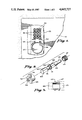
- FIG. 1 shows a front view of a prior art electronic safe lock.
- FIG. 2 is a plan view, partially in section, of the locking mechanism of the present invention in its closed or locked position.
- FIG. 3 is a sectional view taken along line III--III of FIG. 2.
- FIG. 4 is a plan view similar to FIG. 2 showing the lock in its electronically open position.
- FIG. 5 is a sectional view taken along line V--V of FIG. 4 showing in detail the combination lock in its hidden, standby position.
- FIG. 6 is a plan view similar to FIG. 2 showing the mechanical override unlocking mechanism in its unlocked position.
- FIG. 7 is a sectional view taken along line VII--VII of FIG. 6, showing the combination lock dial in its extended position and the mechanical override in its open or unlocked position.
- FIG. 8 is an exploded prospective view of the linkage between the combination lock dial, tumblers and electronic lock cam member.
- FIG. 9 is a side view of the slide bearing portion of the linkage of FIG. 8.
- FIG. 10 is a top plan view of an alternative embodiment having modifications of the solenoid locking arm mechanism.
- FIG. 11 is a sectional view of the modified embodiment taken along line XI--XI of FIG. 10.
- FIG. 12 is an enlarged view showing the solenoid and locking arm modification of FIG. 11.
- the present invention can be used with any electronic digital lock mechanism and includes the provision of an articulated linkage between a manually movable slide plate and associated bolt works which is normally operated after input of the electronic combination effectively unlocks the slide plate.
- the present invention specifically provides a mechanical override of the electronic lock which utilizes an articulated linkage to operate the bolt works in an alternative manner when the slide plate is in its locked or immovable position.
- FIGS. 1, 2 and 3 there is shown a safe door 10 having bolt works 11 for securing the door against the safe.
- the bolt works 11 includes bolts 12 and 13 mounted by "U" brackets 14 and 15 welded to the door 10.
- a bolt operating plate 16 has cam slots 17 and 18 therein for receiving pins 19 and 20 respectively.
- the pins 19 and 20 extend from the locking bolts 12 and 13 to act as cam followers for the slots 17 and 18 to move the locking bolts sideways as shown in FIG. 2 in response to up and down movement of the bolt operating plate 16.
- the "U" brackets 14 and 15 include sidewalls 21, 22, 23 and 24 which act as guide members for the locking bolts 12 and 13.
- a typical digital electronic lock panel is illustrated in FIG. 1 and includes a front housing 25 having numbered buttons 26 for inputting a selected combination and thereafter for inputting the combination to unlock the safe.
- the housing 25 also includes a knob 27 for mechanically moving the bolt works after the correct unlocking combination has been entered.
- the knob 27 includes a reference line 28 so that the user can reference the knob position between the "open” position 29 and the "locked” position 30.
- the exemplary electronic digital lock mechanism includes solenoid 31 activated by user input of the correct electronic combination by way of the panel buttons 26.
- the solenoid 31 operates movable rod 32 which compresses spring 33 and moves lock plate 34 about pivot pin 35 from a first locked position shown in FIG. 2 to a second unlocked position shown in FIG. 4.
- the illustrated lock plate 34 of FIG. 4 includes a notched recess 36 to provide positive locking action with the means for maintaining the safe door locking bolts in their extended locked position.
- An alternative solenoid and lock plate arrangement is shown in FIGS. 10, 11 and 12, discussed below.
- Articulated linkage 40 provides the operable connection between the bolt works 11 and the knob 27.
- the linkage 40 includes link member 41 having a first end 42 pivotally connected by pin 43 to the bolt operating plate 16.
- the link member 41 is connected to slide plate 44 at a mid portion thereof.
- the slide plate head 50 as seen in FIG. 5 functions as the mounting boss for pin 51 pivotally connecting the link member 41 to the slide plate 44.
- Drive cam 52 for moving the slide plate 44 is housed in box section portion 53 of the slide plate and includes a frangible drive part or arm 54.
- the arm 54 is frangible so that in the event that a user attempts to forcibly turn knob 27 when the solenoid 31 has not been activated, for example, when no combination or an incorrect combination has been electronically entered, the frangible arm 54 will break and the cam 52 will move freely without either opening the bolt works 11 or damaging remaining parts of the lock.
- the bolt drive cam 52 also includes a shaped peripheral edge or stop 55 which limits cam rotation to prevent breakage of the frangible arm when the slide plate 44 is freed for movement by input of the correct electronic lock combination.
- the bolt drive cam 52 is mounted about shaft 60, and in operation is rotated by drive part 61.
- the knob 27 is press fit on portion 64 of the shaft 60 with shaft 60 normally held in place by the slide bearing 62 which is press fit on shaft portion 63 and is held by set screw 65 received in recess 67 of the slide bearing 62.
- combination lock 70 includes a cover 71 mounted by screws 72, 73, 74, and 75 (see FIG. 6).
- a cam wheel 76 operates tumbler wheels 77 and 78 mounted on a shaft 79 as more fully described in U.S. Pat. No. 4,142,388, the disclosure of which is incorporated here by reference.
- the lock shaft 79 is driven by drive part 80 mounted on the spindle 60 as shown in FIG. 8.
- a reduced diameter extension 81 to facilitate release of cam 52, a washer 82 which acts as a stop member on axial movement of the spindle, and a spacer section 83.
- the combination lock override of the present invention provides a means for operably connecting the manually operated tumbler wheel combination lock mechanism to the articulated linkage 40 such that when the electronic lock slide plate 44 is fixed in its locked position, the linkage can be operated independent of movement of the slide plate 44 to activate the bolt works 11.
- the connection means between the manual combination lock and the bolt works 11 in the exemplary embodiment includes a lock bolt 85 pivotally connected by pin 86 at an opposite end of the link member 41 relative to the pad connected to pin 43.
- the link member 41 is able to pivot about the pivotal connection 51 upon operation of the combination lock bolt 85.
- the pivotal connection 51 thus acts as a fulcrum for the link member 41 to move the bolt operating plate 16 upwardly from the position of FIG. 5 to that shown in FIG. 6, as the bolt 85 is moved inward by operation of the dial 27 after unlocking of the combination lock by turning the tumbler wheels 77 and 78 through a predetermined sequence.
- the mechanical override can be activated in the following manner.
- the set screw 65 is accessed through the aperture 68 and loosened to permit manual combination lock dial 90 having indicia 91 thereon to be moved out from its hidden recess 92 behind the electronic lock housing 25. Once exposed, input of the tumbler lock combination using the dial 90 aligns the tumbler gates and unlocks the combination lock for movement of the bolt operating plate 16 via the bolt 85 and linkage 40.
- FIGS. 10, 11 and 12 illustrate an alternative embodiment of the mechanical override system of the present invention.
- the solenoid 31 is securely mounted to a mounting bar 99 for example, by screws 101 and 102 such that the solenoid rod 32 moves in a direction parallel to the axis of the slide path 44.
- An arm 99 pivotally mounted to the solenoid rod 32 at 104 and pivotally mounted to the solenoid mounting bar 99 at 105.
- a locking member 106 is secured to the slide plate 44 for engaging recess 108 in the arm 100 and securing the slide plate 44 when the electronic lock is secured in its locked position as shown in FIG. 11.
- This alternative arrangement may provide more positive alignment and hence a more secure abutting relationship between the arm 100 and the locking member 106 while taking up slightly less space than the embodiment shown in FIGS. 2-9.
- the present invention maintains the security inherent in a combination lock system by providing a hidden manual combination lock override unlocking mechanism with an electronic combination lock system.
- the invention utilizes the mechanical bolt works of the electronic system to open the safe while the electronic lock mechanism is in its locked position.
- the invention provides additional security by maintaining the mechanical combination lock dial in a secreted, hidden position until activated by security personnel, and further requires the person accessing the dial to know the mechanical lock's combination before the lock can be opened.
- the mechanical lock utilizes the tumbler mechanism set forth in U.S. Pat. No. 4,142,388 to Phillips, et al. entitled "Tumbler Wheels for Combination Locks".
Abstract
Description
Claims (7)
Priority Applications (1)
| Application Number | Priority Date | Filing Date | Title |
|---|---|---|---|
| US06/815,357 US4665727A (en) | 1985-12-30 | 1985-12-30 | Manually operated lock mechanism for bypass of customer operated electronic digital safe lock |
Applications Claiming Priority (1)
| Application Number | Priority Date | Filing Date | Title |
|---|---|---|---|
| US06/815,357 US4665727A (en) | 1985-12-30 | 1985-12-30 | Manually operated lock mechanism for bypass of customer operated electronic digital safe lock |
Publications (1)
| Publication Number | Publication Date |
|---|---|
| US4665727A true US4665727A (en) | 1987-05-19 |
Family
ID=25217552
Family Applications (1)
| Application Number | Title | Priority Date | Filing Date |
|---|---|---|---|
| US06/815,357 Expired - Fee Related US4665727A (en) | 1985-12-30 | 1985-12-30 | Manually operated lock mechanism for bypass of customer operated electronic digital safe lock |
Country Status (1)
| Country | Link |
|---|---|
| US (1) | US4665727A (en) |
Cited By (46)
| Publication number | Priority date | Publication date | Assignee | Title |
|---|---|---|---|---|
| US4831851A (en) * | 1986-04-10 | 1989-05-23 | Supra Products, Inc. | Combination/electronic lock system |
| US4866961A (en) * | 1987-11-09 | 1989-09-19 | Der Chuan Yang | Non-contact automatic latch lock |
| US4926664A (en) * | 1989-02-16 | 1990-05-22 | Gartner Klaus W | Self locking electronic lock |
| US4949563A (en) * | 1988-07-01 | 1990-08-21 | Ferco International Usine De Ferrures De Batiment S.A.R.L. | Lock for doors, windows or the like |
| US4956984A (en) * | 1988-12-06 | 1990-09-18 | Chi Cheng Lo | Locking device |
| US5010751A (en) * | 1988-02-03 | 1991-04-30 | Omen Metal Products | Safe device and mechanism for operating the same |
| US5020345A (en) * | 1989-02-16 | 1991-06-04 | La Gard, Inc. | Self-locking electronic lock |
| US5033282A (en) * | 1989-02-16 | 1991-07-23 | La Gard, Inc. | Self-locking electronic lock |
| WO1991019068A1 (en) * | 1990-06-06 | 1991-12-12 | La Gard, Inc. | Electro-mechanical lock with rotary bolt |
| US5083448A (en) * | 1988-11-25 | 1992-01-28 | Oy Abloy Security Ltd. | Electromechanical door lock |
| US5113675A (en) * | 1991-01-07 | 1992-05-19 | Uyeda Alan K | Intermediate door locking mechanism |
| US5134870A (en) * | 1990-06-06 | 1992-08-04 | La Gard, Inc. | Electro-mechanical lock with rotary bolt |
| US5172967A (en) * | 1991-08-23 | 1992-12-22 | Meridian Incorporated | Electro-mechanical locking system |
| US5196841A (en) * | 1982-12-03 | 1993-03-23 | Bauer Ag | Vault door locking system featuring microprocessor-based locking means with redundancy control override |
| US5550529A (en) * | 1995-06-26 | 1996-08-27 | Supra Products, Inc. | Access control system |
| US5561995A (en) * | 1993-03-02 | 1996-10-08 | Malcoe Precision Fabrications Ltd. | Door fastener |
| US5575515A (en) * | 1994-02-10 | 1996-11-19 | Fuji Electric Co., Ltd. | Door locking apparatus for dispenser |
| US5628216A (en) * | 1995-01-13 | 1997-05-13 | Schlage Lock Company | Locking device |
| US5697234A (en) * | 1994-05-13 | 1997-12-16 | Diebold, Incorporated | Multiple lock assembly |
| USD388308S (en) * | 1996-12-20 | 1997-12-30 | Mas-Hamilton Group | Electronic combination lock housing |
| US5845523A (en) * | 1994-03-30 | 1998-12-08 | U-Code, Inc. | Electronic input and dial entry lock |
| US5867107A (en) * | 1997-06-03 | 1999-02-02 | Masco Corporation | Variation coded electro-mechanical lock and method of using same |
| US5887467A (en) * | 1994-03-30 | 1999-03-30 | U-Code, Inc. | Pawl & solenoid locking mechanism |
| US5896769A (en) * | 1996-09-13 | 1999-04-27 | Access Technologies, Inc. | Electrically operated actuator |
| US5979199A (en) * | 1996-09-13 | 1999-11-09 | Access Technologies, Inc. | Electrically operated actuator |
| US6000348A (en) * | 1996-09-04 | 1999-12-14 | Citicorp Development Center, Inc. | ATM box or safe with concealed hinges and electronic lock |
| DE19847264A1 (en) * | 1998-10-05 | 2000-04-13 | Secuporta Ges Fuer Sicherheits | Device for locking security doors operates con-rods and a reversing mechanism with sliding lugs connected to a locking bar spanning a door's height and sliding horizontally fitted in a keyway of locking profile sections |
| US6116066A (en) * | 1994-03-30 | 2000-09-12 | Gartner; Klaus W. | Electronic input and dial entry lock |
| DE19602438C2 (en) * | 1995-01-25 | 2000-11-16 | Code Inc U | Combination lock |
| KR100452578B1 (en) * | 2001-05-16 | 2004-10-14 | 닛폰 덴키 가부시끼 가이샤 | Interlock device |
| US20060243008A1 (en) * | 2005-04-29 | 2006-11-02 | Peter Etlicher | Dual dead bolt latch |
| US20080150303A1 (en) * | 2006-11-13 | 2008-06-26 | Van Der Kooij Johannes Jacob H | Assembly comprising a moveable panel, for example a swinging door or window, and a latching mechanism thereof |
| US20090019903A1 (en) * | 2007-07-20 | 2009-01-22 | Ping-Jan Yang | Locking device for truck |
| US20100133270A1 (en) * | 2008-11-28 | 2010-06-03 | Tdk Corporation | Lid opening/closing system for closed container |
| US20100188190A1 (en) * | 2007-07-18 | 2010-07-29 | Iloy Oy | Electromechanical lock |
| US20100281934A1 (en) * | 2009-05-05 | 2010-11-11 | Ming-Jhou Su | Electronic-controlled magnetic lock anti-theft unit for coffer |
| US20110174199A1 (en) * | 2010-01-19 | 2011-07-21 | Bruce Pendleton | Locking Mechanisms for Safes, Such as Gun Safes |
| US20120060726A1 (en) * | 2009-05-22 | 2012-03-15 | Ningbo Yongfa Group Co., Ltd., | Emergently Openable Safe Door |
| US20130106120A1 (en) * | 2010-06-17 | 2013-05-02 | Jan Stendal | Locking device comprising rotating links and guide with sliding element |
| US20160333608A1 (en) * | 2015-05-15 | 2016-11-17 | Michael Earl Ingle | Anti-Bumping Impact Protection Device and Method for Solenoid-Operated Locking Containers |
| USD816463S1 (en) * | 2017-04-11 | 2018-05-01 | Ningbo Tatex Mechtronics Co., Ltd. | Panel for electronic lock |
| USD820065S1 (en) * | 2017-05-11 | 2018-06-12 | Ningbo Tatex Mechtronics Co., Ltd. | Panel for electronic lock |
| USD820066S1 (en) * | 2017-05-12 | 2018-06-12 | Ningbo Tatex Mechtronics Co., Ltd. | Panel for electronic lock |
| USD883068S1 (en) * | 2018-10-31 | 2020-05-05 | Shenzhen Cnest Electronic Technology Co., Ltd. | Door lock |
| USD906086S1 (en) * | 2018-05-23 | 2020-12-29 | Zkteco Co., Ltd. | Smart lock |
| US10909789B2 (en) | 2006-05-31 | 2021-02-02 | Digilock Asia Ltd. | Electronic cam lock for cabinet doors, drawers and other applications |
Citations (23)
| Publication number | Priority date | Publication date | Assignee | Title |
|---|---|---|---|---|
| US450068A (en) * | 1891-04-07 | g-refen | ||
| US473061A (en) * | 1892-04-19 | Setts | ||
| US504462A (en) * | 1893-09-05 | Electric lock | ||
| US613585A (en) * | 1898-11-01 | miner | ||
| US767757A (en) * | 1902-11-21 | 1904-08-16 | Edward B Jacobson | Electric lock. |
| US792404A (en) * | 1903-08-10 | 1905-06-13 | Cons Fire Alarm Company | System for unlocking safes or the like. |
| US1737414A (en) * | 1926-04-21 | 1929-11-26 | Nat Pneumatic Co | Door lock |
| US2020879A (en) * | 1933-07-28 | 1935-11-12 | Glen R Eldred | Protective device |
| US2322724A (en) * | 1941-01-30 | 1943-06-22 | Yale & Towne Mfg Co | Combination lock |
| US2528746A (en) * | 1947-05-19 | 1950-11-07 | Giffin Edward Stanley | Cam-operated latch mechanism |
| US2926516A (en) * | 1956-08-07 | 1960-03-01 | Robert A Poage | Push button combination lock |
| US2947160A (en) * | 1955-11-07 | 1960-08-02 | Sperry Rand Corp | Bolt relocking device for safes |
| US3529454A (en) * | 1968-01-31 | 1970-09-22 | Unican Security Systems | Combination lock controlled electrical instrumentality |
| US3702070A (en) * | 1971-02-19 | 1972-11-07 | Klaus W Gartner | Sequential signal producing means |
| US3758734A (en) * | 1971-05-24 | 1973-09-11 | K Gartner | R means sequential switch means with a linearly movable and rotatable actuato |
| US3968667A (en) * | 1975-07-02 | 1976-07-13 | Sargent & Greenleaf, Inc. | Combination lock construction |
| US4038846A (en) * | 1975-10-24 | 1977-08-02 | Paul Klann | Electronic combination lock |
| US4104896A (en) * | 1977-04-26 | 1978-08-08 | Hahn Hee Mok | Dial lock |
| US4125008A (en) * | 1975-05-13 | 1978-11-14 | Monitron Industries, Inc. | Electrically operated lock |
| GB2000217A (en) * | 1977-06-21 | 1979-01-04 | Philippsthal G | Apparatus for latching together and releasing two parts which are movable relative to one another |
| US4142388A (en) * | 1977-03-30 | 1979-03-06 | Klaus W. Gartner | Tumbler wheels for combination locks |
| US4404823A (en) * | 1980-12-05 | 1983-09-20 | Sargent & Greenleaf, Inc. | View limiting dial and ring structure for combination locks and the like |
| US4468943A (en) * | 1982-09-30 | 1984-09-04 | John D. Brush & Co., Inc. | Live bolt lock mechanism for safe door |
-
1985
- 1985-12-30 US US06/815,357 patent/US4665727A/en not_active Expired - Fee Related
Patent Citations (23)
| Publication number | Priority date | Publication date | Assignee | Title |
|---|---|---|---|---|
| US473061A (en) * | 1892-04-19 | Setts | ||
| US504462A (en) * | 1893-09-05 | Electric lock | ||
| US613585A (en) * | 1898-11-01 | miner | ||
| US450068A (en) * | 1891-04-07 | g-refen | ||
| US767757A (en) * | 1902-11-21 | 1904-08-16 | Edward B Jacobson | Electric lock. |
| US792404A (en) * | 1903-08-10 | 1905-06-13 | Cons Fire Alarm Company | System for unlocking safes or the like. |
| US1737414A (en) * | 1926-04-21 | 1929-11-26 | Nat Pneumatic Co | Door lock |
| US2020879A (en) * | 1933-07-28 | 1935-11-12 | Glen R Eldred | Protective device |
| US2322724A (en) * | 1941-01-30 | 1943-06-22 | Yale & Towne Mfg Co | Combination lock |
| US2528746A (en) * | 1947-05-19 | 1950-11-07 | Giffin Edward Stanley | Cam-operated latch mechanism |
| US2947160A (en) * | 1955-11-07 | 1960-08-02 | Sperry Rand Corp | Bolt relocking device for safes |
| US2926516A (en) * | 1956-08-07 | 1960-03-01 | Robert A Poage | Push button combination lock |
| US3529454A (en) * | 1968-01-31 | 1970-09-22 | Unican Security Systems | Combination lock controlled electrical instrumentality |
| US3702070A (en) * | 1971-02-19 | 1972-11-07 | Klaus W Gartner | Sequential signal producing means |
| US3758734A (en) * | 1971-05-24 | 1973-09-11 | K Gartner | R means sequential switch means with a linearly movable and rotatable actuato |
| US4125008A (en) * | 1975-05-13 | 1978-11-14 | Monitron Industries, Inc. | Electrically operated lock |
| US3968667A (en) * | 1975-07-02 | 1976-07-13 | Sargent & Greenleaf, Inc. | Combination lock construction |
| US4038846A (en) * | 1975-10-24 | 1977-08-02 | Paul Klann | Electronic combination lock |
| US4142388A (en) * | 1977-03-30 | 1979-03-06 | Klaus W. Gartner | Tumbler wheels for combination locks |
| US4104896A (en) * | 1977-04-26 | 1978-08-08 | Hahn Hee Mok | Dial lock |
| GB2000217A (en) * | 1977-06-21 | 1979-01-04 | Philippsthal G | Apparatus for latching together and releasing two parts which are movable relative to one another |
| US4404823A (en) * | 1980-12-05 | 1983-09-20 | Sargent & Greenleaf, Inc. | View limiting dial and ring structure for combination locks and the like |
| US4468943A (en) * | 1982-09-30 | 1984-09-04 | John D. Brush & Co., Inc. | Live bolt lock mechanism for safe door |
Non-Patent Citations (2)
| Title |
|---|
| "Lock Systems" Product Brochure of La Gard, Inc. |
| Lock Systems Product Brochure of La Gard, Inc. * |
Cited By (59)
| Publication number | Priority date | Publication date | Assignee | Title |
|---|---|---|---|---|
| US5196841A (en) * | 1982-12-03 | 1993-03-23 | Bauer Ag | Vault door locking system featuring microprocessor-based locking means with redundancy control override |
| US4831851A (en) * | 1986-04-10 | 1989-05-23 | Supra Products, Inc. | Combination/electronic lock system |
| US4866961A (en) * | 1987-11-09 | 1989-09-19 | Der Chuan Yang | Non-contact automatic latch lock |
| US5010751A (en) * | 1988-02-03 | 1991-04-30 | Omen Metal Products | Safe device and mechanism for operating the same |
| US4949563A (en) * | 1988-07-01 | 1990-08-21 | Ferco International Usine De Ferrures De Batiment S.A.R.L. | Lock for doors, windows or the like |
| US5083448A (en) * | 1988-11-25 | 1992-01-28 | Oy Abloy Security Ltd. | Electromechanical door lock |
| US4956984A (en) * | 1988-12-06 | 1990-09-18 | Chi Cheng Lo | Locking device |
| AU605701B2 (en) * | 1988-12-06 | 1991-01-17 | Lo Chi-Cheng | Locking device |
| US4926664A (en) * | 1989-02-16 | 1990-05-22 | Gartner Klaus W | Self locking electronic lock |
| US5020345A (en) * | 1989-02-16 | 1991-06-04 | La Gard, Inc. | Self-locking electronic lock |
| US5033282A (en) * | 1989-02-16 | 1991-07-23 | La Gard, Inc. | Self-locking electronic lock |
| US5134870A (en) * | 1990-06-06 | 1992-08-04 | La Gard, Inc. | Electro-mechanical lock with rotary bolt |
| US5142890A (en) * | 1990-06-06 | 1992-09-01 | La Gard, Inc. | Electro-mechanical lock with rotary bolt |
| WO1991019068A1 (en) * | 1990-06-06 | 1991-12-12 | La Gard, Inc. | Electro-mechanical lock with rotary bolt |
| US5113675A (en) * | 1991-01-07 | 1992-05-19 | Uyeda Alan K | Intermediate door locking mechanism |
| US5172967A (en) * | 1991-08-23 | 1992-12-22 | Meridian Incorporated | Electro-mechanical locking system |
| US5561995A (en) * | 1993-03-02 | 1996-10-08 | Malcoe Precision Fabrications Ltd. | Door fastener |
| US5575515A (en) * | 1994-02-10 | 1996-11-19 | Fuji Electric Co., Ltd. | Door locking apparatus for dispenser |
| US6298699B1 (en) | 1994-03-30 | 2001-10-09 | U-Code, Inc. | Electronic input and dial entry lock |
| US5845523A (en) * | 1994-03-30 | 1998-12-08 | U-Code, Inc. | Electronic input and dial entry lock |
| US5887467A (en) * | 1994-03-30 | 1999-03-30 | U-Code, Inc. | Pawl & solenoid locking mechanism |
| US6116066A (en) * | 1994-03-30 | 2000-09-12 | Gartner; Klaus W. | Electronic input and dial entry lock |
| US5697234A (en) * | 1994-05-13 | 1997-12-16 | Diebold, Incorporated | Multiple lock assembly |
| US5628216A (en) * | 1995-01-13 | 1997-05-13 | Schlage Lock Company | Locking device |
| DE19602438C2 (en) * | 1995-01-25 | 2000-11-16 | Code Inc U | Combination lock |
| US5550529A (en) * | 1995-06-26 | 1996-08-27 | Supra Products, Inc. | Access control system |
| US6000348A (en) * | 1996-09-04 | 1999-12-14 | Citicorp Development Center, Inc. | ATM box or safe with concealed hinges and electronic lock |
| US6089058A (en) * | 1996-09-13 | 2000-07-18 | Access Technologies, Inc. | Method for retrofitting a deadbolt assembly with an electrically operated actuator |
| US5979199A (en) * | 1996-09-13 | 1999-11-09 | Access Technologies, Inc. | Electrically operated actuator |
| US5896769A (en) * | 1996-09-13 | 1999-04-27 | Access Technologies, Inc. | Electrically operated actuator |
| US6282931B1 (en) | 1996-09-13 | 2001-09-04 | Access Technologies, Inc. | Electrically operated actuator and method |
| USD388308S (en) * | 1996-12-20 | 1997-12-30 | Mas-Hamilton Group | Electronic combination lock housing |
| US5867107A (en) * | 1997-06-03 | 1999-02-02 | Masco Corporation | Variation coded electro-mechanical lock and method of using same |
| DE19847264A1 (en) * | 1998-10-05 | 2000-04-13 | Secuporta Ges Fuer Sicherheits | Device for locking security doors operates con-rods and a reversing mechanism with sliding lugs connected to a locking bar spanning a door's height and sliding horizontally fitted in a keyway of locking profile sections |
| KR100452578B1 (en) * | 2001-05-16 | 2004-10-14 | 닛폰 덴키 가부시끼 가이샤 | Interlock device |
| US20060243008A1 (en) * | 2005-04-29 | 2006-11-02 | Peter Etlicher | Dual dead bolt latch |
| US7445254B2 (en) * | 2005-04-29 | 2008-11-04 | Truth Hardware Corporation | Dual dead bolt latch |
| US10909789B2 (en) | 2006-05-31 | 2021-02-02 | Digilock Asia Ltd. | Electronic cam lock for cabinet doors, drawers and other applications |
| US10930099B2 (en) | 2006-05-31 | 2021-02-23 | Digilock Asia Ltd. | Electronic cam lock for cabinet doors, drawers and other applications |
| US20080150303A1 (en) * | 2006-11-13 | 2008-06-26 | Van Der Kooij Johannes Jacob H | Assembly comprising a moveable panel, for example a swinging door or window, and a latching mechanism thereof |
| US8231148B2 (en) * | 2006-11-13 | 2012-07-31 | Johannes Jacob Hans Willem Van Der Kooij | Assembly comprising a moveable panel, for example a swinging door or window, and a latching mechanism thereof |
| US20100188190A1 (en) * | 2007-07-18 | 2010-07-29 | Iloy Oy | Electromechanical lock |
| US8981899B2 (en) * | 2007-07-18 | 2015-03-17 | Iloq Oy | Electromechanical lock |
| US7784315B2 (en) * | 2007-07-20 | 2010-08-31 | Ping-Jan Yang | Locking device for truck |
| US20090019903A1 (en) * | 2007-07-20 | 2009-01-22 | Ping-Jan Yang | Locking device for truck |
| US20100133270A1 (en) * | 2008-11-28 | 2010-06-03 | Tdk Corporation | Lid opening/closing system for closed container |
| US8657346B2 (en) * | 2008-11-28 | 2014-02-25 | Tdk Corporation | Lid opening/closing system for closed container |
| US20100281934A1 (en) * | 2009-05-05 | 2010-11-11 | Ming-Jhou Su | Electronic-controlled magnetic lock anti-theft unit for coffer |
| US20120060726A1 (en) * | 2009-05-22 | 2012-03-15 | Ningbo Yongfa Group Co., Ltd., | Emergently Openable Safe Door |
| US9097057B2 (en) * | 2010-01-19 | 2015-08-04 | Pendleton Safe Company | Locking mechanisms for safes, such as gun safes |
| US20110174199A1 (en) * | 2010-01-19 | 2011-07-21 | Bruce Pendleton | Locking Mechanisms for Safes, Such as Gun Safes |
| US20130106120A1 (en) * | 2010-06-17 | 2013-05-02 | Jan Stendal | Locking device comprising rotating links and guide with sliding element |
| US9273499B2 (en) * | 2010-06-17 | 2016-03-01 | Stendals El Ab | Locking device comprising rotating links and guide with sliding element |
| US20160333608A1 (en) * | 2015-05-15 | 2016-11-17 | Michael Earl Ingle | Anti-Bumping Impact Protection Device and Method for Solenoid-Operated Locking Containers |
| USD816463S1 (en) * | 2017-04-11 | 2018-05-01 | Ningbo Tatex Mechtronics Co., Ltd. | Panel for electronic lock |
| USD820065S1 (en) * | 2017-05-11 | 2018-06-12 | Ningbo Tatex Mechtronics Co., Ltd. | Panel for electronic lock |
| USD820066S1 (en) * | 2017-05-12 | 2018-06-12 | Ningbo Tatex Mechtronics Co., Ltd. | Panel for electronic lock |
| USD906086S1 (en) * | 2018-05-23 | 2020-12-29 | Zkteco Co., Ltd. | Smart lock |
| USD883068S1 (en) * | 2018-10-31 | 2020-05-05 | Shenzhen Cnest Electronic Technology Co., Ltd. | Door lock |
Similar Documents
| Publication | Publication Date | Title |
|---|---|---|
| US4665727A (en) | Manually operated lock mechanism for bypass of customer operated electronic digital safe lock | |
| US6298699B1 (en) | Electronic input and dial entry lock | |
| US5794466A (en) | Key safe for housing a key | |
| US4917022A (en) | Safe having motor-driven locking mechanism | |
| US5887467A (en) | Pawl & solenoid locking mechanism | |
| US8161781B2 (en) | Electronic locker lock | |
| CA1282607C (en) | Combination/electronic lock system | |
| US6938445B2 (en) | Mortise lock status indicator | |
| US8225629B2 (en) | Portable lock with electronic lock actuator | |
| US5460020A (en) | Key safe | |
| US5845523A (en) | Electronic input and dial entry lock | |
| US7007524B2 (en) | Dead bolt lock system having multiple security features | |
| US6622534B1 (en) | Dead bolt system having multiple security features | |
| US7424814B2 (en) | Dead bolt lock system having multiple security features | |
| US20040003633A1 (en) | Electronic lock system | |
| US5010751A (en) | Safe device and mechanism for operating the same | |
| US5791174A (en) | Paddle handle locks | |
| US4031725A (en) | Door lock | |
| JPH0821134A (en) | Combination lock with adjustment button | |
| JPH07119533B2 (en) | Electric locking device | |
| JPH08135279A (en) | Lock handle device of door used for both right and left hands | |
| WO2004020769A1 (en) | Lock | |
| US4709566A (en) | Single cylinder deadbolt lock mechanism | |
| US2766608A (en) | Antimanipulative combination lock | |
| JP2512396Y2 (en) | Crescent with lock |
Legal Events
| Date | Code | Title | Description |
|---|---|---|---|
| AS | Assignment |
Owner name: UYEDA, ALAN K. 8316 ELSMORE DRIVE, ROSEMEAD, CA. 9 Free format text: ASSIGNS TO EACH ASSIGNEE THE PERCENTAGE OPPOSITE THEIR RESPECTIVE NAMES.;ASSIGNOR:UYEDA, TIM;REEL/FRAME:004516/0887 Effective date: 19841101 Owner name: PHILLIPS, PETER J. 828 CALLE DE ARBOLES, REDONDO B Free format text: ASSIGNS TO EACH ASSIGNEE THE PERCENTAGE OPPOSITE THEIR RESPECTIVE NAMES.;ASSIGNOR:UYEDA, TIM;REEL/FRAME:004516/0887 Effective date: 19841101 Owner name: GARTNER, KLAUS W. 2632 VIA ANCAPA, PALOS VERDES ES Free format text: ASSIGNS TO EACH ASSIGNEE THE PERCENTAGE OPPOSITE THEIR RESPECTIVE NAMES.;ASSIGNOR:UYEDA, TIM;REEL/FRAME:004516/0887 Effective date: 19841101 Owner name: UYEDA, ALAN K. (15%),CALIFORNIA Free format text: ASSIGNS TO EACH ASSIGNEE THE PERCENTAGE OPPOSITE THEIR RESPECTIVE NAMES;ASSIGNOR:UYEDA, TIM;REEL/FRAME:004516/0887 Effective date: 19841101 Owner name: PHILLIPS, (15%),CALIFORNIA Free format text: ASSIGNS TO EACH ASSIGNEE THE PERCENTAGE OPPOSITE THEIR RESPECTIVE NAMES;ASSIGNOR:UYEDA, TIM;REEL/FRAME:004516/0887 Effective date: 19841101 Owner name: GARTNER, KLAUS W. (35%),CALIFORNIA Free format text: ASSIGNS TO EACH ASSIGNEE THE PERCENTAGE OPPOSITE THEIR RESPECTIVE NAMES;ASSIGNOR:UYEDA, TIM;REEL/FRAME:004516/0887 Effective date: 19841101 |
|
| FEPP | Fee payment procedure |
Free format text: PAYOR NUMBER ASSIGNED (ORIGINAL EVENT CODE: ASPN); ENTITY STATUS OF PATENT OWNER: SMALL ENTITY |
|
| FPAY | Fee payment |
Year of fee payment: 4 |
|
| FPAY | Fee payment |
Year of fee payment: 8 |
|
| REMI | Maintenance fee reminder mailed | ||
| LAPS | Lapse for failure to pay maintenance fees | ||
| FP | Lapsed due to failure to pay maintenance fee |
Effective date: 19990519 |
|
| STCH | Information on status: patent discontinuation |
Free format text: PATENT EXPIRED DUE TO NONPAYMENT OF MAINTENANCE FEES UNDER 37 CFR 1.362 |