US4695385A - Dialyzer reuse system - Google Patents
Dialyzer reuse system Download PDFInfo
- Publication number
- US4695385A US4695385A US06/728,204 US72820485A US4695385A US 4695385 A US4695385 A US 4695385A US 72820485 A US72820485 A US 72820485A US 4695385 A US4695385 A US 4695385A
- Authority
- US
- United States
- Prior art keywords
- dialyzer
- reuse
- fluid
- blood
- disinfecting
- Prior art date
- Legal status (The legal status is an assumption and is not a legal conclusion. Google has not performed a legal analysis and makes no representation as to the accuracy of the status listed.)
- Expired - Lifetime
Links
Images


Classifications
-
- A—HUMAN NECESSITIES
- A61—MEDICAL OR VETERINARY SCIENCE; HYGIENE
- A61L—METHODS OR APPARATUS FOR STERILISING MATERIALS OR OBJECTS IN GENERAL; DISINFECTION, STERILISATION OR DEODORISATION OF AIR; CHEMICAL ASPECTS OF BANDAGES, DRESSINGS, ABSORBENT PADS OR SURGICAL ARTICLES; MATERIALS FOR BANDAGES, DRESSINGS, ABSORBENT PADS OR SURGICAL ARTICLES
- A61L2/00—Methods or apparatus for disinfecting or sterilising materials or objects other than foodstuffs or contact lenses; Accessories therefor
- A61L2/16—Methods or apparatus for disinfecting or sterilising materials or objects other than foodstuffs or contact lenses; Accessories therefor using chemical substances
- A61L2/18—Liquid substances or solutions comprising solids or dissolved gases
-
- A—HUMAN NECESSITIES
- A61—MEDICAL OR VETERINARY SCIENCE; HYGIENE
- A61M—DEVICES FOR INTRODUCING MEDIA INTO, OR ONTO, THE BODY; DEVICES FOR TRANSDUCING BODY MEDIA OR FOR TAKING MEDIA FROM THE BODY; DEVICES FOR PRODUCING OR ENDING SLEEP OR STUPOR
- A61M1/00—Suction or pumping devices for medical purposes; Devices for carrying-off, for treatment of, or for carrying-over, body-liquids; Drainage systems
- A61M1/14—Dialysis systems; Artificial kidneys; Blood oxygenators ; Reciprocating systems for treatment of body fluids, e.g. single needle systems for hemofiltration or pheresis
- A61M1/16—Dialysis systems; Artificial kidneys; Blood oxygenators ; Reciprocating systems for treatment of body fluids, e.g. single needle systems for hemofiltration or pheresis with membranes
- A61M1/168—Sterilisation or cleaning before or after use
- A61M1/1682—Sterilisation or cleaning before or after use both machine and membrane module, i.e. also the module blood side
- A61M1/1684—Checking the module characteristics before reuse
-
- A—HUMAN NECESSITIES
- A61—MEDICAL OR VETERINARY SCIENCE; HYGIENE
- A61M—DEVICES FOR INTRODUCING MEDIA INTO, OR ONTO, THE BODY; DEVICES FOR TRANSDUCING BODY MEDIA OR FOR TAKING MEDIA FROM THE BODY; DEVICES FOR PRODUCING OR ENDING SLEEP OR STUPOR
- A61M1/00—Suction or pumping devices for medical purposes; Devices for carrying-off, for treatment of, or for carrying-over, body-liquids; Drainage systems
- A61M1/14—Dialysis systems; Artificial kidneys; Blood oxygenators ; Reciprocating systems for treatment of body fluids, e.g. single needle systems for hemofiltration or pheresis
- A61M1/16—Dialysis systems; Artificial kidneys; Blood oxygenators ; Reciprocating systems for treatment of body fluids, e.g. single needle systems for hemofiltration or pheresis with membranes
- A61M1/168—Sterilisation or cleaning before or after use
- A61M1/169—Sterilisation or cleaning before or after use using chemical substances
Definitions
- Hemodialysis has been well known as a means for circulating a patient's blood on one side of a membrane which has "minute pores" through which waste products from the blood may pass but which are too small to permit blood cells and protein to be lost.
- a dialysis fluid generated by e hemodialysis machine is circulated on the opposite side of the membrane to flush and remove these waste products as they are dissipated.
- the patient's blood is passed through the dialyzer for various periods of time up to six hours with this type of treatment repeated several times each week.
- Various critical problems occur in the use of this type of treatment in that the dialyzer and the hemodialysis machine must be cleaned and disinfected after each use to prevent contamination and complications to the patient.
- dialyzer In the early 1970's, a major step was taken in that the dialyzer was improved and perfected in a disposable form that was considerably cheaper than the previous dialyzers used. Even in this new disposable form, the dialyzer costs average between $25 and $35. Because these dialyzers are intended to be disposable, they eliminate the problems connected with the cleaning and sterilizing of the dialyzer before subsequent use. However, because of the relatively high cost of the disposable dialyzer and, in addition, the cost of the blood tube set that is required to be used with the dialyzer, the expense of the individual treatments to the patient is still quite high primarily because of the required continuing treatment.
- the present invention was developed as a means for vastly improving the reuse cycle for the dialyzer and blood tubing sets in order to improve and correct the various deficiencies which have been noted in the prior art devices and systems.
- the Shaldon patent (U.S. Pat. No. 3,871,913) discloses a system for supplying a blood dialyzer with dialyzing fluid and connections enabling the system to be connected with the dialysate and blood compartments in parallel after a dialysis treatment.
- the dialysate supply system is used to supply washing and sterilizing liquids both to the blood chamber and dialysis chamber of the dialyzer simultaneously during the reuse process.
- the Mellor patent (U.S. Pat. No. 3,753,493) discloses a cleaning apparatus for artificial kidneys or dialyzers.
- the device provides automatic cleaning and sterilizing of the dialyzer through an automatic arrangement of solenoids, valves and timer.
- a parate receptacle is provided on the device for a fluid supply with the concentrated fluids being proportionately mixed with the water supply inlet through a venturi device.
- the operation of this device is mechanical with the solenoid valves operated electrically by the timer.
- the Serrox, et al. patent (U.S. Pat. No. 3,441,136) discloses an early dialyzer reuse device in that the device provides a logic unit which programs the dialysis system through cycles of operation in which the entire system, including the dialyzer, is rinsed, sterilized and cooled with water and in which monitors are provided to test the system to verify that it meets critical parameters before a hemodialysis treatment is started.
- the preliminary operation provides a rinse of the system and dialyzer with water with the sterilizing operations providing a continuous flush with high temperature water.
- the entire system is again flushed with water to cool down components with the system then filled with dialysis fluid.
- a test cycle of the dialyzer is then performed prior to the actual dialysis treatment function.
- the Hardy patent U.S. Pat. No. 4,166,031 discloses a dialyzer cleaning apparatus which circulates cleaning, flushing and sterilizing solutions through the dialysate and blood chambers of the dialyzer in a parallel flow arrangement.
- the system utilizes solenoid valves to regulate and sequence fluid flow at the proper time.
- a venturi system is utilized to proportionately dilute and mix the cleaning and sterilizing fluids prior to passage through the dialyzer chambers.
- the Mason patent (U.S. Pat. No. 3,920,030) also discloses a reuse device for cleaning and disinfecting artificial kidneys. This patent discloses the use of enclosed tubular pumps for moving the solution through the system. In addition, solenoids are utilized to pinch or close off resilient tubes for blocking the flow in certain lines.
- the device is designed so that the tubular manifold unit of the device can be separated and replaced with other units for different patients. Thus, each manifold unit can be maintained unique to each patient.
- a reuse system for cleansing and disinfecting dialyzers, blood tubing sets and hemodialysis machines which includes a basic automatic reuse device, a flow adapter valve and a blood tube manifold. Through the use of these devices, a completely automatic system is provided for the reuse of dialyzers or artificial kidneys and for a test certification sequence before actual reuse of the dialyzer.
- the reuse device is connected to a suitable source of water with additional input connections to reservoirs or bottles containing the concentrated cleansing and disinfecting solutions.
- the controlled fluid output from the reuse device is connected to a negative pressure or vacuum point in the dialysate pathway of the hemodialysis machine.
- the vacuum draws solutions from the reservoirs through the reuse device and into the dialysis machine which thoroughly dilutes and mixes prior to the cleaning, rinsing and sterilization cycles.
- the electrical power for the dialysis machine is connected through the reuse device which automatically controls the primary electrical power to the dialysis machine during its operation, cleansing and reuse cycle.
- the adapter valve is installed in the external tubing network of the hemodialysis machine, including a connection to the dialyzer. This valve permits the rerouting of the liquid lines depending upon the phase of the operation that is in progress without disconnecting the lines which can violate the integrity of the system by introducing contamination or bacteria.
- the blood tubing manifold provides a path for flow through the peripheral pressure sensing and medication lines which are required during the dialysis process. This manifold is connected in parallel so that reliable and complete cleansing and disinfecting of these lines will be performed.
- the reuse system characterizes the dialyzer by means of a clearance test to certify the integrity of the dialyzer prior to reuse. This test is performed in a closed loop arrangement which retains the sterility of the system with no possibility of contamination.
- the only break in the main blood tubing line is effected when the blood lines are connected to the patient. All other primary blood lines remain intact as well as those primary lines on the dialysate side of the dialyzer.
- An interlock switch is provided on the reuse device to change over operation of the system from reuse to dialyzer test and normal operation.
- the actuation of the switch engages an occluding roller blocking the output line on the device to assure the integrity of the dialyzer test.
- This switch is primarily a safety feature, preventing solution flow through the device during testing and normal operation.
- the clearance test provided by this system not only validates the integrity of the dialyzer but the entire hemodialysis machine and system as well.
- Operation of the reuse cycle is controlled by a suitably programmed and replaceable memory.
- This circuitry is bad on an internal clock which performs the automatic functions of the system.
- the actual status of the system during the operation and test is displayed by easily visible indicator lights.
- the overall operation of the system is extremely simple and straightforward with the entire system capable of being operated by a person or patient with only minimal training.
- This arrangement can be easily adapted for individual use in a home setting, and also can be utilized in dialysis centers.
- FIG. 1 shows a pictorial view of the system according to the present invention connected to a dialyzer and a hemodialysis machine;
- FIG. 2 shows a perspective front view of the reuse device according to the present invention
- FIG. 3 shows a perspective rear view of the same device
- FIG. 4 shows a partial pictorial view of the interlock switch shown on the rear panel of the reuse device
- FIG. 5a and 5b is a block diagram showing the operational section of the reuse device
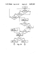
- FIG. 6a and 6b is a logic diagram showing the cleaning and disinfecting function of the reuse system
- FIG. 7a and 7b is a logic diagram showing the dialyzer test function of the device
- FIG. 8 is a perspective view of the flow adapter valve which is part of the reuse system
- FIG. 9 shows a bottom perspective view of the adapter valve handle showing the fluid recesses
- FIG. 10 is a cross-sectional view taken along lines 10--10 of FIG. 8;
- FIG. 11 is a cross-sectional view taken along lines 11--11 of FIG. 8;
- FIG. 12 shows a pictorial flow diagram of the flow adapter valve positioned during clearance testing and normal dialysis treatment
- FIG. 13 is a pictorial flow diagram of the adapter valve during the reuse cycle
- FIG. 14 is a pictorial flow diagram of the adapter valve which allows the flow to be intermittently reversed through the dialyzer for cleaning purposes;
- FIG. 15 shows a pictorial diagram of the system connected to the dialyzer and hemodialysis machine during the reuse cleaning and disinfecting operation;
- FIG. 16 is a partial flow diagram showing the adapter valve in the reverse flow configuration.
- FIG. 17 is a partial pictorial view showing the adapter valve in the dialyzer test and normal dialysis configuration.
- FIG. 1 shows a reuse system 10 according to the present invention which is semipermanently connected to a hemodialysis machine M and an artificial kidney or dialyzer D.
- Blood drip chambers C1 and C2 are provided upstream and downstream of the dialyzer D to control the flow of blood through the dialyzer as well as remove any air bubbles which might be present.
- a roller type blood pump P or some other type of suitable pump is provided on the dialysis machine M to aid in movement of the blood from the patient, through the dialyzer, and back to the patient. This same pump is also utilized during the dialyzer test cycle to circulate the fluid in the blood chamber side of the dialyzer during the clearance test as well as flushing of the diinfectant remaining in the closed loop, as will be explained later.
- the reuse system 10 includes the reuse device 12, adapter valve 14 and blood tubing manifold 16.
- the reuse device 12 is connected to input tubes 18, 20 which are flow connected to reservoirs B and F, which contain concentrates of a cleaning solution and a disinfecting solution, respectively.
- the cleaning solution can be of any suitab1 solution such as sodium hypochlorite which is commonly known as household bleach.
- the sodium hypochlorite solution or standard bleach is of a 5.25% concentration prior to being introduced into the system.
- the disinfecting solution can be any suitable solution such as an aqueous formaldehyde solution having a 37% USP grade concentration plus 80 grams of sodium chloride (agent grade) and 0.4 grams FD&C blue dye per gallon. Since the formaldehyde solution is quite toxic, the blue dye is added as an identifier to indicate the presence of the formaldehyde within the system. This is a precautionary safety feature which is provided to prevent accidental introduction of the formaldehyde solution to the patient. It is also important to note that the reservoirs B and F are substantially sealed, unbreakable containers which help to minimize the release of any fumes of either the bleach or formaldehyde into the atmosphere which can be irritating or detrimental to humans.
- the reuse device 12 is connected into the dialysis machine M by means of the output tube 22.
- the output tube 22 introduces solutions of bleach or formaldehyde into the dialysis machine M in which water is continuously flowing when dialysate is not being generated.
- the connection of this output tube 22 is made at a negative pressure or vacuum point in the dialysate preparation and conditioning section of the machine M.
- the output line 24 of the dialysis machine M which normally carries dialysate, connects directly into the inlet 26 for the dialysate chamber of the dialyzer D.
- Outlet 28 of the dialysate chamber is connected by tubing 30 to the dialysate input 32 of the adapter valve 14.
- valve 14 With the handle of the adapter valve 34 in the reuse position, the flow passes through valve 14 to arterial fitting 58, tubing 60 to blood pump segment 44.
- the pump segment 44 is not installed during the reuse cycle.
- Flow continues to arterial drip chamber C1 and out bloodline 46.
- Arterial monitor line 47 and saline line 57 are attached to manifold 16.
- Branching off of bloodline 46 is the heparin line 59 which is also attached to manifold 16.
- Flow goes into the blood side of the dialyzer D through arterial fitting 48, out through venous fitting 50 and into the venous drip chamber C2 by bloodline 52.
- the venous monitor line is connected to manifold 16 thus providing the parallel pathway through the manifold 16.
- Flow continues through bloodline 54 into venous connection 56 on adapter 14.
- the flow is routed through to fitting 35, tubing 36, tee 38 and conductivity sensor 42 and effluent drain line 40.
- the conductivity sensor is electrically connected by suitable wires
- the fluid in the blood chamber of the dialyzer is recirculated in the blood tubing closed loop.
- This closed loop consists of the tube 44 which is part of the blood tubing set which is positioned within the blood pump P provided on the dialysis machine M which in turn is connected to the drip chamber C1, tube 46 and the arterial blood connection 48 on the dialyzer D.
- Tube 52 which is connected through the venous drip chamber C2 and tube 54 to the venous blood connector 56 on the adapter valve 14. With the handle in the proper position flow goes directly across the valve to arterial fitting 58, through tube 60, to the blood pump segment 44, completing the blood side loop.
- the outside configuration of the reuse device 12 is shown in FIGS. 2 and 3.
- the novel reuse device 12 includes an outside cover 64, a front panel 65 and a back panel 67.
- the front operational panel 65 has a mode selection switch 66 to set the operation of the device either in the reuse or dialyzer test function.
- the remaining portion of the front panel 65 is divided into sections 70 and 72 which are catagorized for the two operational functions.
- the reuse section 70 includes "start" push switch 74 and test status indicator lights 76.
- the dialyzer test section 72 includes the "start” push switch 78 and indicator lights 80.
- Each of the indicator lights 76 and 80 are of a different color with its function printed just below on the front panel 65.
- the back cover 67 of the reuse device 12 includes apertures for the electrical power cable 82 and auxiliary power outlet 84.
- the power cord from the associated hemodialysis machine M is connected to the auxiliary power outlet 84 so that the "on-off" operation of the machine can be controlled by the reuse device.
- Suitable fuse holders 86 are provided in the power supply portion of the device to protect the electrical components of the system. Moving to the right of the fuses 86 is the cable or wires 88 for the conductivity probe 42.
- an accessory control receptacle 90 and three voltage test connectors 92 to which a volt meter or other test equipment can be connected to provide a visual readout of the conductivity and temperature of the fluids.
- the accessory control receptacle is wired to an internal relay to control various functions within the hemodialysis machine, as desired.
- the incoming water line 21 is connected to a suitable continuous source of filtered water. This source can conveniently found in the hydraulic section of the dialysis machine M to which the line 21 can be connected.
- interlock switch 94 which provides both an electrical switching as well as a mechanical valving function.
- An eccentrically located roller 100 is provided on the operating knob 95 located 90° from the function designating arrow.
- the output fluid tube 22 from the reuse device 12 is routed over a bracket 96 which has a flat upper surface 98 and clamps 99 which hold the flexible tube 22 in rigid position adjacent to the outer circumferential surface of the knob 95.
- the roller 100 is brought into close proximity to the upper surface 98 of the bracket 96 which completely pinches off or occludes the output tube 22.
- This is a safety device which prevents any flow of liquid from the reuse device 12 during the dialyzer test function or during normal dialysis treatment. In this way, the clearance test, as will be discussed later, is completely isolated from the reuse device to be certain that the results of the test are accurate and reflect the true condition of the dialyzer.
- FIG. 5 shows a block diagram of the operations of the reuse device 12 according to the present invention.
- Power plug 82 is connected to a 115VAC, 50-60 HZ source of electrical power.
- the power supply 102 provides power to operate the electronic circuitry as well as the fluid control valves and indicator lights. Power is fed from the power supply 102 to the internal logic device 104 which provides the selector-logic functions for the operation of the reuse device 12.
- Mode switch 66 which is found on the front panel 65 and interlock switch 94 which is controlled by knob 95 on the rear panel 67 are electrically connected to the function selector and reset logic device 104.
- both the mode switch 66 and the interlock switch 94 be in the equivalent electrical position either for the reuse function or the dialyzer test function.
- either the reuse start push button switch 74 or dialyzer test push button switch 78 located on the front panel 65 is actuated to start the desired function.
- Oscillator 108 and dividers 110 and 112 generate a system clock.
- the time base for the error lamp 149 and horn 150 is a product of the system clock.
- the system clock is divided further to generate time base for the duration of each portion of the reuse cycle.
- the output signal from the divider 112 is fed to the address decoders 114, 116 and 118 which, in turn, sequentially retrieve the data instructions from the memory 120, which has been programmed to control the operation of the reuse cycle.
- the output commands of the memory 120 directly access the appropriate external function drivers 124, 126, 132, 134, 130, 128 and 216.
- the clean valve driver opens the clean valve 125 and simultaneously, the clean light driver 126 energizes the clean light 127.
- the energizing of the bleach control valve allows bleach to be drawn through the device and into the output tube.
- This output solution of bleach passes from the output line 22 to the input of the hemodialysis machine M where it is mixed with the machine water flow to obtain the desired level of dilution.
- the memory 120 switches the clean valve driver and thus deactivates the bleach control valve. Simultaneously, the clean range detector 136 is activated. This range detector is programmed to check the conductivity of the cleaning cycle fluid and if it is not within predetermined limits, the detector actuates the clean range latch 138, the clean error LED 139, the error lamp 149 and the horn 150.
- the rinse light driver 128 is energized causing the rinse light to be illuminated.
- the cycle continues to the end of rinse at which point the rinse cycle range detector 140 is activated. If the predetermined parameters of conductivity are not met, the rinse range latch 142 is activated causing the rinse error LED 143, the error lamp 149 and the horn 150 to be activated.
- the disinfect valve driver 130 Upon completion of the timing of the rinse cycle, the disinfect valve driver 130 is energized which activates the formaldehyde control valve 131 permitting the highly concentrated disinfect solution to be drawn through the output line 22. Simultaneously, the disinfect light driver 132 and disinfect indicator light 133 are energized.
- the disinfect range detector 144 is activated. Failure of the disinfect solution conductivity to be within the predetermined range actuates the disinfect range latch 146 energizing the error LED 147, the error light 149 and the horn 150. It is to be noted that when any of the error functions have been activated, the remaining functions of the device are not interrupted.
- the last stage in the reuse cycle is a short delay, about a minute, allowing the water to rinse the formaldehyde from the output line 22.
- all drivers are deactivated allowing the device to appear idle. In this "resting" condition, water continues to flow through the device providing for an internal rinse of valves and other components.
- the clean light driver 126, the disinfect light driver 132 and the rinse light driver 128 are activated causing the respective lights 127, 133 and 129 to be illuminated.
- the operational relay driver 216 is deactivated shutting off power to auxiliary outlet 90 and thus the dialysis machine.
- the temperature and conductivity probe 42 is connected to a temperature compensated circuit whose voltage output is proportional to conductivity.
- the signal is electrically doubled and then fed as input to range detectors.
- a test point 92a which provides a readout signal of the conductivity.
- Another test point 92b is also provided for readout of the temperature.
- the initial range detector initiates the operation of the run light during the test cycle.
- the test timing is automatically started and the conductivity output is monitored continuously. If the conductivity reading rises into a required minimum range prior to the end of the predetermined time period for the test, the pass range detector initiates the pass range latch 197 which energizes the pass light driver 198 and pass light 199. On the other hand, if the conductivity does not reach the required minimum range by the end of the test run, the fail range detector output signal energizes the fail range latch 202 which initiates the fail light driver 204 and the fail light 206.
- the output signal from the fail range detector 196 is fed to the fail direction detector 208 which differentiates whether the conductivity reading was above or below the required predetermined range which initiates the fail direction latch and either the low light driver 211 and light 212 or the high light driver 213 and light 214. In this way if the dialyzer clearance test has failed, the user will have an indication as to what condition caused the failure of the dialyzer.
- the test time is started when the dialysate leaving the dialyzer reaches a conductivity of 6 millimhos and the conductivity must reach a range of 8.5 to 11.0 millimhos within a time period of 22 seconds.
- FIGS. 6 and 7 show the logic process performed by the circuit in accomplishing the reuse and dialyzer test procedures.
- FIG. 6 the reuse cycle of the device is described. The steps in this logic sequence follow the same general pattern as previously discussed in the block diagrams.
- the entire cycle for the reuse operation is initiated by the start switch function. At this point, both the interlock switch and the mode switch are checked to make sure that they are in the reuse position. If either one is not, the cycle cannot be started until the switches are set in the proper position.
- the start light within the switch 74 is illuminated, the bleach control valve is opened, and the cleaning cycle is started. The time for the cleaning cycle is monitored, and the cleaning process continues until the pre-set time period is completed.
- the cleaning lamp and bleach control valve are de-energized and a check is made of the conductivity of the fluid downstream of the dialyzer. If this conductivity at this time is out of the desired predetermined range, an error function is initiated with the error light and error signal horn or beeper initiated.
- the rinse cycle is then initiated. During this cycle, the time is monitored and upon expiration, a second conductivity check is made to determine if the conductivity of the fluid flow now present is within the proper range. If the fluid is out of range at this point the error light 149, the horn 150 and the water error LED 143 are initiated. Again, the process will continue regardless of an error signal.
- a third conductivity check is performed at the end of the disinfect cycle. If the conductivity is out of the predetermined range, indicating that the concentration or substance of the disinfectant is in error, the error light and signal beeper are promptly initiated.
- a short time delay is provided. This time delay allows the output line to be rinsed of formaldehyde. After the delay the solid state relay is de-energized shutting off power to auxiliary outlet 90.
- the memory 120 sends a signal to turn all status lights (126, 129, and 133) on and to a 5-volt relay 135, opening at least a pair of contacts.
- the entire dialysis system including the dialyzer, blood lines, hemodialysis machine and reuse device, is left intact for storage; thus, the disinfecting solution remains in the entire system during the storage period which maintains the sterility of all components and tubes and prevents contamination or growth of any bacteria.
- the adapter valve 14 is turned so as to place the valve in proper position for the normal patient dialysis treatment. This isolates the dialysate chamber and tubing of the dialyzer from the blood chamber and tubing. Thus, the dialyzer blood tubing forms a closed loop which still contains the disinfectant solution, such as the 4% solution of formaldehyde.
- dialysate side of the dialyzer and its associated tubing is connected directly to the output of the hemodialysis machine.
- concentrated dialysate is being diluted, conditioned and allowed to temporarily bypass to the drain to allow the dialysate flow to stabilize with the proper concentration and temperature. Once the system has stabilized, the dialyzer clearance test can begin.
- This test as shown in FIG. 7 is initiated by verifying that the interlock switch 94 provided on the back panel of the device 12 is in the proper position for the test mode with the output line 22 from the device blocked or closed.
- the mode switch 66 on the front panel is also verified to be in the dialyzer test position. With both switches in the correct position, the push button start switch 78 for the dialyzer test is initiated.
- the dialysate from the hemodialysis machine M is switched to flow through the dialyzer and the blood pump is started to circulate the fluid in the blood tubing closed loop. The conductivity of the dialysate is monitored continuously. When the conductivity of the dialysate rises to the correct reading, the timer in the reuse device is initiated.
- the conductivity of the dialysate leaving the dialyzer is monitored and must reach a desired range before the timer completes the predetermined cycle. If the conductivity before the end of the time period is within the predetermined range, the dialyzer is considered to be satisfactory and has passed the clearance test. At this point, the pass light is turned on and the test is completed. If, however, the conductivity is out of the desired range, the fail light is initiated and either the or low fail light is also initiated depending upon the actual conductivity reading. In this way, the user is made aware that the dialyzer has failed the test with the additional information as to the condition of the dialyzer membrane. At this point, the test is completed.
- Disinfectant solution still remains in the blood tubing circuit. While dialysate continuously flows through the dialysate chamber of the dialyzer, the disinfectant solution is recirculated through the blood tubing lines. With molecular transfer across the dialyzer membrane, the disinfectant is transferred across the membrane where it is disposed with the dialysate. This process continues until complete flushing is accomplished.
- the condition of the fluid within the blood lines is visually checked to make sure that the disinfectant or formaldehyde solution containing a blue dye indicator has been completely removed from the system. Once this has been visually verified, a chemical test is performed to verify that no formaldehyde or disinfectant residual solution remains in either side of the system. Once the flushing process has been completed and verified, the blood line can be separated and connected to the patient for the treatment process.
- the adapter flow valve 14 which permits the rerouting of the flow path during the reuse and dialyzer test cycles is shown in FIG. 15.
- the adapter valve 14 includes a body 230 which can be molded or cast or machined usually from a solid block of material.
- a handle 34 mounted on top of the body 230 permits the actual switching of the flow path through the valve.
- the handle 34 has an elongated ridge 35 which extends diametrically across the upper surface. This ridge is provided as a finger grip to facilitate the rotation of the handle 34 in switching the valve 14.
- a drilled bore 232 is provided in the handle 34.
- a cap screw 233 is positioned through the aperture 232 and engaged with the threaded aperture 234 provided in the center of the body 230.
- An O-ring 236 is provided under the head of the cap screw 233 to seal the internal cavity provided on the underside of the handle.
- the underside of the handle 34 has an elongated central recess 238 and two oppositely spaced recesses 240 and 242, respectively.
- the aperture 232 penetrates through the elongated cavity 238 thus necessitating the seal or O-ring 236.
- An O-ring groove and O-ring 244 are provided around the entire perimeter of the under surface 237 of the handle 34.
- O-ring seals 246, 248 and 250 are positioned around the perimeter of the recesses 240, 242 and 238, respectively. These seals are also spaced slightly from the edge of the recesses to provide suitable O-ring grooves for sealing purposes.
- the input dialysate line 32 is connected to the body of the valve 14 by a tube fitting 260 mounted in the threaded aperture 262.
- the threaded aperture is connected to the top surface 231 of the valve body 230 by a drilled L-shaped passageway 264.
- the dialysate output line 36 is joined to the valve by means of the fitting 266, mounted in the threaded aperture 268.
- the threaded aperture 268 is, in turn, connected to the top surface 231 by means of a drilled L-shaped passageway 270.
- the openings of the passageways 264, 270 in the surface 231 are located diametrically opposite each other and equal distant from the center tapped hole 234.
- the radius of these openings matches the diameter of the elongated recess 238. In this way, with the elongated recess diametrically aligned along the longitudinal axis of the body 230, the input and output dialysis lines 32, 36 have a common flow path through the recess 238.
- Blood line connectors 56, 58 are mounted on opposite sides of the valve body 230 on an axis which is through the body center aperture and 90° to the axis between the dialysate lines 32, 36.
- the blood fitting is mounted on the side of the valve body 230 in a threaded aperture 280 which, in turn, is connected to a drilled passageway 282.
- the venous blood fitting 58 is threadably mounted in the aperture 284 which, in turn, is connected by an angled drilled passageway 286.
- the ends of the passageways 282, 286 communicate with the top surface 231 of valve body 230 which correspond to the cavities provided by the recesses 240, 242, respectively.
- openings are also spaced the same radius from the center threaded aperture 234 as the openings to the dialysate passageways. Thus, all four of the openings align on a circle having an equal radius from the center aperture of the valve body.
- the recesses 238, 240, 242 are shaped so that the handle 34 can be rotated 45° in either direction from center which will change the flow path from a straight-through dialysate flow to one where the input from tube 32 and output from tube 36 can be alternately switched between the arterial and venous tubes.
- Pin 290 is mounted so as to protrude from the upper edge of the handle 34 in alignment with the ridge 35.
- a pair of stop pins 292, 294 are positioned at 45° angles from the center position and adjacent to the outer circumference of the handle 34. In this way the pin 290 and the stops 292, 294 prevent the handle 34 from being rotated beyond the 45° position in either direction to restrict rotation of the handle 34 and limit the adapter valve to the three desired flow path positions. It is also possible to provide a detent mechanism in the handle to supplement or replace the stop-pin 290.
- FIG. 12 illustrates the flow path of the adapter valve 14 with the handle shown in the center or normal position of FIG. 12. In this arrangement, the flow is directed in through the line 32 and out through the line 36. The flow between fittings 58 and 56 is blocked except for the bypass line 296.
- FIG. 13 illustrates the flow path of the adapter in ithe reuse position. Flow is through input line 32 and out through blood arterial fitting 56. This goes through the blood side loop and into fitting 58, then out through fitting 36. With the handle turned in the opposite position, the flow is through the fitting 32 and out through the venous fitting 58, through the blood side loop and then into the arterial fitting 56 and out through fitting 36.
- the adapter valve position shown in FIG. 12 is utilized during the dialyzer test and normal dialysis treatment process.
- the arrangement shown in ia FIG. 13 is commonly used during the reuse process when cleaning and disinfecting the dialyzer system.
- the reuse system primarily includes the reuse device 12, the adapter valve 14 and the blood tubing manifold 16. Once the dialysis treatment has been completed on the patient, a rinse back procedure is provided to remove much of the blood which is present in the blood tubing set and return the blood to the patient.
- the reuse device 12 is permanently or semi-permanently connected into the dialysis machine system and is intended to remain connected during further use.
- the adapter valve 14 is also connected into the dialysate and blood lines of the hemodialysis machine and allowed to remain connected during all operations. Once the rinse back procedure has been accomplished and the blood tubing has been disconnected from the patient, the ends of the blood lines are connected to the blood connector fittings 56, 58 on the adapter valve 14. At the same time the blood pressure lines 47, 49 and heparin injection line 51 and medication line 53 are connected to the ports of the manifold.
- FIG. 15 shows the flow diagram of the overall system during the reuse cycle.
- the main inlet power cable from the hemodialysis machine is connected to the auxiliary power receptacle 84 on the reuse device 12.
- the output tube 22 from the reuse device is connected to a tee 302 at a low pressure vacuum point in the internal dialysate tubing 304, 306 within the hemodialysis machine M/
- An air removal pump 308 de-airs the dialysate which flows into dialyzer D by connector 26.
- tubing connection and arrangements shown in FIG. 15 are essentially the same as those shown in FIG. 1 with the exception of the blood line 44 mounted within the blood pump P.
- the transition between the different processes can be easily made without breaking or disconnecting primary tubes or fittings to accomplish the overall purpose.
- the reuse cleaning flow from the dialysate machine to the system is usually set at 500 milliliters per minute.
- the reuse process is initiated by pushing the reuse start button.
- concentrated bleach (5.25% solution) is drawn from the reservoir B and enters the dialysis machine through tee 302.
- this solution is mixed with the water flow to dilute it to the proper percentage of concentration (0.25%).
- This solution then passes through the air removal pump 308, through the dialyzer D and out through the connector 28 and to the adapter valve 14.
- the cleaning solution passes through the valve 14, blood fitting 56 and blood tube 54 where it flows upward through the venous drip chamber C2 and then through the dialyzer D. This flow is counter to the normal flow of blood through the dialyzer.
- the cleaning solution flows through the arterial drip chamber Cl returning to the adapter valve through the connector 63 and edication fittings 61, 62.
- the flow crosses over the adapter valve and out through the line 36, conductivity probe 42 and drain line 40.
- the conductivity of the fluid is measured by the probe 42 to verify that the proper solution is being used during the various stages of the cycle.
- the reuse device times the cleaning cycle for approximately twenty minutes and then automatically switches to a water only flush cycle for approximately five minutes.
- the bleach is shut off and the normal water flow through the reuse device and machine is used to rinse the entire system for the desired time period.
- a disinfecting solution such as concentrated formaldehyde (37% solution) is drawn from the reservoir F. This solution then passes into the machine where it is diluted to a concentration of approximately 4%. This solution then passes through the system tubing in the same flow path as previously described for a period of approximately eight minutes. After this time period, the disinfectant flow is stopped, and a minute delay is provided during which water flows through the device allowing for a rinseout of the output line 22 of formaldehyde.
- the hemodialysis machine M is switched off via receptacle 84, preventing the disinfect solution from being rinsed out of the machine. In this way, the dialyzer, blood lines and hemodialysis machine are filled with the disinfectant solution, and this solution remains in the entire system during the nonuse or storage period.
- the conductivity probe checks, at the end of each stage of the cycle, the conductivity of the fluid passing through the system.
- the conductivity during the cleaning process must be within range of six to twelve millimhos.
- the conductivity will drop to the range of zero to two millimhos.
- the conductivity will again rise to approximately two to six millimhos.
- This is especially important during the disinfecting cycle to verify the presence of the disinfectant to maintain the sterility of the system during the nonuse or storage period. This is a primary verification test in addition to the secondary visual observation of the blue color of the disinfecting solution due to the presence of the added dye.
- the reuse device is switched to the "Dialyzer Test" mode which rests the system and applies power to the hemodialysis machine M.
- the dialysis machine is switched to a "rinse” mode, and the machine concentrate line is dropped in concentrate allowing the machine to produce dialysate.
- the machine is also in the "bypass” mode to avoid flowing dialysate fluid past the dialyzer prior to the test.
- the adapter valve is switched to the "normal" dialysis position at this time. This separates the two fluid flow paths through the dialyzer.
- the blood pump section is placed into the blood pump P. This is easily done by allowing the pump to run for a couple of revolutions and feeding the tubing from one end of the pump. The pump, however, must not continue to run at this time.
- the start switch 78 for "Dialyzer Test” is depressed, illuminating the start lamp and initiating the dialyzer testing function.
- the dialysis machine M flow rate is preset at 500 milliliters per minute and the blood pump flow rate is set at 200 milliliters per minute. Simultaneously, the dialysis machine M is taken out of "bypass” and the blood pump is turned on.
- a loop is completed for the blood side path by the bypass line 296 in the adapter valve 14.
- a counter-current flow is established, “dialyzing” formaldehyde from the blood side and electrolites from the dialysate side. This reduces the effluent dialysate conductivity (concentration).
- the timed test period is initiated.
- a stable condition will be reached in a short time, during which the conductivity must be in a range of 8.5 to 11.0 millimhos for a satisfactory pass of the dialyzer's clearance.
- the fail light on the reuse device is automatically illuminated along with the light indicating the high or low condition.
- a high conductivity reading indicates that the dialyzer clearance is low.
- a low conductivity reading means that the dialyzer may have a leak across the membrane, which would be unsatisfactory during the dialysis treatment. In either case where the test has failed, it is necessary to replace the dialyzer with a new unit prior to the patient treatment.
- the dialysate flow is continued for a period of twenty-two to thirty minutes and the blood pump operation is continued.
- the formaldehyde fluid remaining in the blood tubing is recirculated and dissipated across the dialyzer membrane at the same time saline solution is added to the blood side to replace the volume of fluid lost.
- saline solution is added to the blood side to replace the volume of fluid lost.
- This process continues until the formaldehyde has been completely removed from the blood lines.
- a chemical test is made on the fluid in both the blood side as well as the dialysate side of the dialyzer to verify that no formaldehyde is present in either system. Once this verification has been made, the dialyzer, blood lines and hemodialysis machine are ready to be used for dialysis treatment of the patient.
- the blood line connections 56, 58 are the only primary tubes which must be disconnected and reconnected to the patient.
- the only other connections which need to be disturbed are the auxiliary or secondary blood lines on the machine such as the drip chamber lines 47 and 49 and medication injection lines 51 and 53. These lines are reattached to the proper connections on the hemodialysis machine M for the proper functioning of the machine. In this way the integrity and sterility of the blood tubing set is maintained as completely as possible.
Abstract
Description
Claims (12)
Priority Applications (1)
| Application Number | Priority Date | Filing Date | Title |
|---|---|---|---|
| US06/728,204 US4695385A (en) | 1985-04-29 | 1985-04-29 | Dialyzer reuse system |
Applications Claiming Priority (1)
| Application Number | Priority Date | Filing Date | Title |
|---|---|---|---|
| US06/728,204 US4695385A (en) | 1985-04-29 | 1985-04-29 | Dialyzer reuse system |
Publications (1)
| Publication Number | Publication Date |
|---|---|
| US4695385A true US4695385A (en) | 1987-09-22 |
Family
ID=24925849
Family Applications (1)
| Application Number | Title | Priority Date | Filing Date |
|---|---|---|---|
| US06/728,204 Expired - Lifetime US4695385A (en) | 1985-04-29 | 1985-04-29 | Dialyzer reuse system |
Country Status (1)
| Country | Link |
|---|---|
| US (1) | US4695385A (en) |
Cited By (97)
| Publication number | Priority date | Publication date | Assignee | Title |
|---|---|---|---|---|
| US4783273A (en) * | 1987-01-29 | 1988-11-08 | Gambro Ab | Method and apparatus for supplying concentrate for use in medical treatments |
| US4784771A (en) * | 1987-08-03 | 1988-11-15 | Environmental Water Technology, Inc. | Method and apparatus for purifying fluids |
| US4918019A (en) * | 1986-05-12 | 1990-04-17 | C. D. Medical, Incorporated | Bioreactor system with plasticizer removal |
| US5078967A (en) * | 1988-10-13 | 1992-01-07 | Dibios S.A. | Method of cleaning, disinfecting and sterilizing hemodialysis apparatus |
| US5110477A (en) * | 1990-02-13 | 1992-05-05 | Howard David B | Dialyzer clearance check system |
| US5147613A (en) * | 1989-11-04 | 1992-09-15 | Fresenius Ag | Apparatus for sterilizing a medical unit |
| WO1993009821A1 (en) * | 1991-11-15 | 1993-05-27 | Baxter International Inc. | Automated hemodialysis chemical treatment system |
| US5268144A (en) * | 1989-11-04 | 1993-12-07 | Fresenius Ag | Method for sterilizing a medical unit |
| US5279735A (en) * | 1991-07-25 | 1994-01-18 | Minntech Corporation | Sterilant solutions for hollow fiber membranes |
| US5336165A (en) * | 1991-08-21 | 1994-08-09 | Twardowski Zbylut J | Artificial kidney for frequent (daily) Hemodialysis |
| US5480565A (en) * | 1993-10-08 | 1996-01-02 | Levin; Nathan | Methods for disinfecting dialyzers |
| WO1996025214A1 (en) * | 1995-02-13 | 1996-08-22 | Aksys, Ltd. | Modular home dialysis system |
| US5685835A (en) * | 1995-06-07 | 1997-11-11 | Cobe Laboratories, Inc. | Technique for using a dialysis machine to disinfect a blood tubing set |
| US5759489A (en) * | 1995-01-17 | 1998-06-02 | Miura-Denshi Kabushiki-Kaisha | Washing and disinfecting method and apparatus for artificial dialyzer using acid water electrolytically made |
| US5772624A (en) * | 1995-07-20 | 1998-06-30 | Medisystems Technology Corporation | Reusable blood lines |
| US5837204A (en) * | 1994-01-31 | 1998-11-17 | Universite De Montreal | System for disinfecting the water lines of a dental unit |
| US5851483A (en) * | 1988-11-23 | 1998-12-22 | L'air Liquide, Societe Anonyme Pour L'etude Et L'exploitation Des Procedes Georges Claude | Hygienic agent for use in hemodialysis |
| US5895578A (en) * | 1996-06-18 | 1999-04-20 | Hospal Industrie | Method of disinfection for a dialysis machine |
| US5902476A (en) * | 1991-08-21 | 1999-05-11 | Twardowski; Zbylut J. | Artificial kidney for frequent (daily) hemodialysis |
| WO2000012991A1 (en) | 1998-08-26 | 2000-03-09 | Aksys, Ltd. | Blood tubing set integrity tests for extracorporeal circuits |
| US6050278A (en) * | 1998-09-24 | 2000-04-18 | Minntech Corporation | Dialyzer precleaning system |
| US6080321A (en) * | 1996-09-06 | 2000-06-27 | Fresenius Medical Care Deutschland Gmbh | Dialysis machine for the removal of toxic substances from the blood with agents for the decalcification of a dialysis liquid circulation as well as process for determining the degree of calcification of a dialysis machine |
| US6153102A (en) * | 1995-02-13 | 2000-11-28 | Aksys, Ltd. | Disinfection of dead-ended lines in medical instruments |
| US20020112743A1 (en) * | 1997-06-23 | 2002-08-22 | Yacoob Tabani | Method for cleaning hollow tubing and fibers |
| US20020131890A1 (en) * | 2000-09-27 | 2002-09-19 | Huth Stanley W. | Reuse determination for high level disinfectant |
| US6454871B1 (en) * | 1997-06-23 | 2002-09-24 | Princeton Trade & Technology, Inc. | Method of cleaning passageways using a mixed phase flow of gas and a liquid |
| US6468472B1 (en) | 1999-09-16 | 2002-10-22 | Metrex Research Corporation | Cleaning and decontaminating dialyzers by per-compound solutions |
| EP1266668A1 (en) * | 2001-06-12 | 2002-12-18 | Fresenius Medical Care Deutschland GmbH | Method for detection of impurities in a rinsing liquid for rinsing an extracorporeal blood treatment system and apparatus using same |
| US6499495B2 (en) | 2001-01-24 | 2002-12-31 | Allegiance Corporation | Waste treatment system for suction canisters |
| US20030100857A1 (en) * | 2000-01-12 | 2003-05-29 | Renato Pedrazzi | Method for emptying a blood circuit of an apparatus for the extracorporeal treatment of blood |
| US6655394B1 (en) * | 1996-09-26 | 2003-12-02 | Noriaki Tanaka | Method and apparatus for reprocessing dialyzers |
| US20040007255A1 (en) * | 1997-06-20 | 2004-01-15 | Labib Mohamed Emam | Apparatus and method for cleaning pipelines, tubing and membranes using two-phase flow |
| KR100419552B1 (en) * | 2001-05-28 | 2004-02-19 | 주식회사 사이언씨티 | Dialyser Reuse Machine equipped with the Electrolyed-Solution production device and its reprocessing method |
| US20050028845A1 (en) * | 1997-06-23 | 2005-02-10 | Labib Mohamed Emam | Cleaning composition and apparatus for removing biofilm and debris from lines and tubing and method therefor |
| US20060079827A1 (en) * | 2004-10-07 | 2006-04-13 | Mel Jensen | Blood flow reversal valves and related systems and methods |
| EP1892000A1 (en) * | 2006-08-22 | 2008-02-27 | B. Braun Medizintechnologie GmbH | Method for priming the filter element of a dialysis machine |
| US20080253911A1 (en) * | 2007-02-27 | 2008-10-16 | Deka Products Limited Partnership | Pumping Cassette |
| US20080257824A1 (en) * | 2007-04-23 | 2008-10-23 | Square Peg Engineering, Llc | Method and Apparatus for Water Purification and Regeneration of Micro-filtration Tubules |
| US20090004053A1 (en) * | 2007-06-29 | 2009-01-01 | Kenley Rodney S | Devices, systems, and methods for cleaning, disinfecting, rinsing, and priming blood separation devices and associated fluid lines |
| US20090317311A1 (en) * | 2007-02-01 | 2009-12-24 | Johnsondiversey, Inc. | Dispenser control systems and methods |
| US20100078047A1 (en) * | 2008-09-30 | 2010-04-01 | Mohamed Emam Labib | Method and composition for cleaning tubular systems employing moving three-phase contact lines |
| US20100078046A1 (en) * | 2008-09-30 | 2010-04-01 | Mohamed Emam Labib | Apparatus and method for cleaning passageways such as endoscope channels using flow of liquid and gas |
| US7744553B2 (en) | 2003-12-16 | 2010-06-29 | Baxter International Inc. | Medical fluid therapy flow control systems and methods |
| US20100181235A1 (en) * | 2007-05-25 | 2010-07-22 | Gambro Lundia Ab | device for connecting to a liquid source |
| US20100206784A1 (en) * | 2009-02-18 | 2010-08-19 | Fresenius Medical Care Holdings, Inc. | Extracorporeal Fluid Circuit and Related Components |
| US7862660B2 (en) | 2007-01-12 | 2011-01-04 | Princeton Trade & Technology, Inc. | Device and method for fluid dynamics cleaning of constrained spaces |
| US7892197B2 (en) | 2007-09-19 | 2011-02-22 | Fresenius Medical Care Holdings, Inc. | Automatic prime of an extracorporeal blood circuit |
| US20110108474A1 (en) * | 2005-10-21 | 2011-05-12 | Fresenius Medical Care Holdings, Inc. | Extracorporeal fluid circuit |
| US20110163030A1 (en) * | 2010-01-07 | 2011-07-07 | Fresenius Medical Care Holdings, Inc. | Dialysis Systems and Methods |
| US20110210054A1 (en) * | 2007-09-19 | 2011-09-01 | Fresenius Medical Care Holdings, Inc. | Safety vent structure for extracorporeal circuit |
| US8246826B2 (en) | 2007-02-27 | 2012-08-21 | Deka Products Limited Partnership | Hemodialysis systems and methods |
| US8292594B2 (en) | 2006-04-14 | 2012-10-23 | Deka Products Limited Partnership | Fluid pumping systems, devices and methods |
| US8343346B2 (en) | 2007-09-19 | 2013-01-01 | Fresenius Medical Care Holdings, Inc. | Dialysis systems and related components |
| US8357298B2 (en) | 2007-02-27 | 2013-01-22 | Deka Products Limited Partnership | Hemodialysis systems and methods |
| US8393690B2 (en) | 2007-02-27 | 2013-03-12 | Deka Products Limited Partnership | Enclosure for a portable hemodialysis system |
| US8409441B2 (en) | 2007-02-27 | 2013-04-02 | Deka Products Limited Partnership | Blood treatment systems and methods |
| US8425471B2 (en) | 2007-02-27 | 2013-04-23 | Deka Products Limited Partnership | Reagent supply for a hemodialysis system |
| US8491184B2 (en) | 2007-02-27 | 2013-07-23 | Deka Products Limited Partnership | Sensor apparatus systems, devices and methods |
| US8499780B2 (en) | 2007-02-27 | 2013-08-06 | Deka Products Limited Partnership | Cassette system integrated apparatus |
| US8506684B2 (en) | 2010-12-15 | 2013-08-13 | Fresenius Medical Care Holdings, Inc. | Gas release devices for extracorporeal fluid circuits and related methods |
| US8562834B2 (en) * | 2007-02-27 | 2013-10-22 | Deka Products Limited Partnership | Modular assembly for a portable hemodialysis system |
| US20140221960A1 (en) * | 2013-02-07 | 2014-08-07 | Stihler Electronic Gmbh | Fluid warmer and method of operating a fluid warmer |
| US8894600B2 (en) | 2003-11-05 | 2014-11-25 | Baxter International Inc. | Hemodialysis system including on-line dialysate generation |
| US9028691B2 (en) * | 2007-02-27 | 2015-05-12 | Deka Products Limited Partnership | Blood circuit assembly for a hemodialysis system |
| US9220832B2 (en) | 2010-01-07 | 2015-12-29 | Fresenius Medical Care Holdings, Inc. | Dialysis systems and methods |
| EP3031482A1 (en) * | 2014-12-10 | 2016-06-15 | Medtronic, Inc. | Water management system for use in dialysis |
| US9375526B2 (en) | 2013-06-25 | 2016-06-28 | Fresenius Medical Care Holdings, Inc. | Vial spiking assemblies and related methods |
| US9415151B2 (en) | 2012-09-25 | 2016-08-16 | Fresenius Medical Care Holdings, Inc. | Blood flow reversal valves and related systems and methods |
| US9517295B2 (en) | 2007-02-27 | 2016-12-13 | Deka Products Limited Partnership | Blood treatment systems and methods |
| US9561317B2 (en) | 2002-04-11 | 2017-02-07 | Deka Products Limited Partnership | System and method for delivering a target volume of fluid |
| US9597442B2 (en) | 2007-02-27 | 2017-03-21 | Deka Products Limited Partnership | Air trap for a medical infusion device |
| EP3170519A1 (en) * | 2015-11-18 | 2017-05-24 | B. Braun Avitum AG | Method for sterilizing and integrity verification of dialyzers |
| US9713665B2 (en) | 2014-12-10 | 2017-07-25 | Medtronic, Inc. | Degassing system for dialysis |
| US9724458B2 (en) | 2011-05-24 | 2017-08-08 | Deka Products Limited Partnership | Hemodialysis system |
| WO2017198814A1 (en) * | 2016-05-20 | 2017-11-23 | Fresenius Medical Care Deutschland Gmbh | Medical device with a time-controlled starting function |
| US9872949B2 (en) | 2013-02-01 | 2018-01-23 | Medtronic, Inc. | Systems and methods for multifunctional volumetric fluid control |
| CN107802906A (en) * | 2017-11-21 | 2018-03-16 | 四川大学华西医院 | A kind of blood purification system |
| US9945838B2 (en) | 2015-12-17 | 2018-04-17 | Fresenius Medical Care Holdings, Inc. | Extracorporeal circuit blood chamber having an integrated deaeration device |
| US9974942B2 (en) | 2015-06-19 | 2018-05-22 | Fresenius Medical Care Holdings, Inc. | Non-vented vial drug delivery |
| US10010663B2 (en) | 2013-02-01 | 2018-07-03 | Medtronic, Inc. | Fluid circuit for delivery of renal replacement therapies |
| WO2018153881A1 (en) * | 2017-02-23 | 2018-08-30 | Fresenius Medical Care Deutschland Gmbh | Extracorporeal blood treatment device and method for operating an extracorporeal blood treatment device |
| US10098993B2 (en) | 2014-12-10 | 2018-10-16 | Medtronic, Inc. | Sensing and storage system for fluid balance |
| US10201650B2 (en) | 2009-10-30 | 2019-02-12 | Deka Products Limited Partnership | Apparatus and method for detecting disconnection of an intravascular access device |
| US10201647B2 (en) | 2008-01-23 | 2019-02-12 | Deka Products Limited Partnership | Medical treatment system and methods using a plurality of fluid lines |
| US10463774B2 (en) | 2007-02-27 | 2019-11-05 | Deka Products Limited Partnership | Control systems and methods for blood or fluid handling medical devices |
| US10537671B2 (en) | 2006-04-14 | 2020-01-21 | Deka Products Limited Partnership | Automated control mechanisms in a hemodialysis apparatus |
| US10543052B2 (en) | 2013-02-01 | 2020-01-28 | Medtronic, Inc. | Portable dialysis cabinet |
| US10695481B2 (en) | 2011-08-02 | 2020-06-30 | Medtronic, Inc. | Hemodialysis system having a flow path with a controlled compliant volume |
| CN111658862A (en) * | 2020-06-09 | 2020-09-15 | 济南市章丘区中医医院 | Intelligent hemodialysis device |
| US10850016B2 (en) | 2013-02-01 | 2020-12-01 | Medtronic, Inc. | Modular fluid therapy system having jumpered flow paths and systems and methods for cleaning and disinfection |
| US10857277B2 (en) | 2011-08-16 | 2020-12-08 | Medtronic, Inc. | Modular hemodialysis system |
| US10874787B2 (en) | 2014-12-10 | 2020-12-29 | Medtronic, Inc. | Degassing system for dialysis |
| US11033667B2 (en) | 2018-02-02 | 2021-06-15 | Medtronic, Inc. | Sorbent manifold for a dialysis system |
| US11033671B2 (en) | 2011-05-24 | 2021-06-15 | Deka Products Limited Partnership | Systems and methods for detecting vascular access disconnection |
| US11110215B2 (en) | 2018-02-23 | 2021-09-07 | Medtronic, Inc. | Degasser and vent manifolds for dialysis |
| US11253636B2 (en) | 2008-01-23 | 2022-02-22 | Deka Products Limited Partnership | Disposable components for fluid line autoconnect systems and methods |
| US11278654B2 (en) | 2017-12-07 | 2022-03-22 | Medtronic, Inc. | Pneumatic manifold for a dialysis system |
Citations (11)
| Publication number | Priority date | Publication date | Assignee | Title |
|---|---|---|---|---|
| US3342328A (en) * | 1966-04-14 | 1967-09-19 | Harvey F Swenson | Dialyzer membrane storage assembly |
| US3441136A (en) * | 1966-07-07 | 1969-04-29 | Milton Roy Co | Controlled blood dialysis system |
| US3753493A (en) * | 1971-04-23 | 1973-08-21 | E Mellor | Artificial kidney cleaning apparatus |
| US3871913A (en) * | 1972-03-14 | 1975-03-18 | Dialysis Systems Limited | Cleaning of dialyser compartments and blood lines of artificial kidney machine |
| US3920030A (en) * | 1974-10-18 | 1975-11-18 | Made Inc | Device for cleaning and sterilizing artificial kidneys |
| US4153554A (en) * | 1977-02-22 | 1979-05-08 | American Micro-Bionics Corp. | Apparatus for use in artificial kidney system |
| US4166031A (en) * | 1976-05-21 | 1979-08-28 | Dean Hardy | Artificial kidney cleaning apparatus and process |
| US4332264A (en) * | 1980-03-03 | 1982-06-01 | United Healthcare Association | Automated cleaning system for dialyzers |
| US4444597A (en) * | 1980-03-03 | 1984-04-24 | Norman Gortz | Automated cleaning method for dialyzers |
| US4444596A (en) * | 1980-03-03 | 1984-04-24 | Norman Gortz | Automated cleaning method for dialyzers |
| US4517081A (en) * | 1981-11-17 | 1985-05-14 | Renal Systems, Inc. | Dialyzer reuse machine |
-
1985
- 1985-04-29 US US06/728,204 patent/US4695385A/en not_active Expired - Lifetime
Patent Citations (11)
| Publication number | Priority date | Publication date | Assignee | Title |
|---|---|---|---|---|
| US3342328A (en) * | 1966-04-14 | 1967-09-19 | Harvey F Swenson | Dialyzer membrane storage assembly |
| US3441136A (en) * | 1966-07-07 | 1969-04-29 | Milton Roy Co | Controlled blood dialysis system |
| US3753493A (en) * | 1971-04-23 | 1973-08-21 | E Mellor | Artificial kidney cleaning apparatus |
| US3871913A (en) * | 1972-03-14 | 1975-03-18 | Dialysis Systems Limited | Cleaning of dialyser compartments and blood lines of artificial kidney machine |
| US3920030A (en) * | 1974-10-18 | 1975-11-18 | Made Inc | Device for cleaning and sterilizing artificial kidneys |
| US4166031A (en) * | 1976-05-21 | 1979-08-28 | Dean Hardy | Artificial kidney cleaning apparatus and process |
| US4153554A (en) * | 1977-02-22 | 1979-05-08 | American Micro-Bionics Corp. | Apparatus for use in artificial kidney system |
| US4332264A (en) * | 1980-03-03 | 1982-06-01 | United Healthcare Association | Automated cleaning system for dialyzers |
| US4444597A (en) * | 1980-03-03 | 1984-04-24 | Norman Gortz | Automated cleaning method for dialyzers |
| US4444596A (en) * | 1980-03-03 | 1984-04-24 | Norman Gortz | Automated cleaning method for dialyzers |
| US4517081A (en) * | 1981-11-17 | 1985-05-14 | Renal Systems, Inc. | Dialyzer reuse machine |
Non-Patent Citations (2)
| Title |
|---|
| Simultaneous Reprocessing of Hollow Fiber Dialyzers and Blood Tubing Sets for Multiple Use by David A. Ogden, pp. 366 375, Published in Dialysis & Transplantation, vol. 13, No. 6, Jun., 1984. * |
| Simultaneous Reprocessing of Hollow Fiber Dialyzers and Blood Tubing Sets for Multiple Use by David A. Ogden, pp. 366-375, Published in Dialysis & Transplantation, vol. 13, No. 6, Jun., 1984. |
Cited By (240)
| Publication number | Priority date | Publication date | Assignee | Title |
|---|---|---|---|---|
| US4918019A (en) * | 1986-05-12 | 1990-04-17 | C. D. Medical, Incorporated | Bioreactor system with plasticizer removal |
| US4783273A (en) * | 1987-01-29 | 1988-11-08 | Gambro Ab | Method and apparatus for supplying concentrate for use in medical treatments |
| US4784771A (en) * | 1987-08-03 | 1988-11-15 | Environmental Water Technology, Inc. | Method and apparatus for purifying fluids |
| US5078967A (en) * | 1988-10-13 | 1992-01-07 | Dibios S.A. | Method of cleaning, disinfecting and sterilizing hemodialysis apparatus |
| US5851483A (en) * | 1988-11-23 | 1998-12-22 | L'air Liquide, Societe Anonyme Pour L'etude Et L'exploitation Des Procedes Georges Claude | Hygienic agent for use in hemodialysis |
| US6162394A (en) * | 1988-11-23 | 2000-12-19 | L'air Liquide, Societe Anonyme Pour L'etude Et L'exploitation Des Procedes Georges Claude | Hygienic agent for use in hemodialysis |
| US5147613A (en) * | 1989-11-04 | 1992-09-15 | Fresenius Ag | Apparatus for sterilizing a medical unit |
| US5268144A (en) * | 1989-11-04 | 1993-12-07 | Fresenius Ag | Method for sterilizing a medical unit |
| US5110477A (en) * | 1990-02-13 | 1992-05-05 | Howard David B | Dialyzer clearance check system |
| US5279735A (en) * | 1991-07-25 | 1994-01-18 | Minntech Corporation | Sterilant solutions for hollow fiber membranes |
| US5902476A (en) * | 1991-08-21 | 1999-05-11 | Twardowski; Zbylut J. | Artificial kidney for frequent (daily) hemodialysis |
| US5484397A (en) * | 1991-08-21 | 1996-01-16 | Twardowski; Zbylut J. | Artificial kidney for frequent (daily) hemodialysis |
| US6146536A (en) * | 1991-08-21 | 2000-11-14 | Twardowski; Zbylut J. | Method of preparing a batch of dialysis solution |
| US6132616A (en) * | 1991-08-21 | 2000-10-17 | Twardowski; Zbylut J. | Method for flushing and filling of an extracorporeal blood circulation system of a dialysis machine |
| US5336165A (en) * | 1991-08-21 | 1994-08-09 | Twardowski Zbylut J | Artificial kidney for frequent (daily) Hemodialysis |
| EP0701827A3 (en) * | 1991-11-15 | 1996-05-01 | Baxter Int | |
| EP0701829A3 (en) * | 1991-11-15 | 1996-05-01 | Baxter Int | |
| EP0701828A3 (en) * | 1991-11-15 | 1996-05-01 | Baxter Int | |
| WO1993009821A1 (en) * | 1991-11-15 | 1993-05-27 | Baxter International Inc. | Automated hemodialysis chemical treatment system |
| US5698100A (en) * | 1993-10-08 | 1997-12-16 | Levin; Nathan | Bacteriostatic dialyzers containing citric acid solutions |
| US5480565A (en) * | 1993-10-08 | 1996-01-02 | Levin; Nathan | Methods for disinfecting dialyzers |
| US5837204A (en) * | 1994-01-31 | 1998-11-17 | Universite De Montreal | System for disinfecting the water lines of a dental unit |
| US5759489A (en) * | 1995-01-17 | 1998-06-02 | Miura-Denshi Kabushiki-Kaisha | Washing and disinfecting method and apparatus for artificial dialyzer using acid water electrolytically made |
| US5674397A (en) * | 1995-02-13 | 1997-10-07 | Aksys, Ltd. | Debubblers |
| US5725776A (en) * | 1995-02-13 | 1998-03-10 | Aksys, Ltd. | Methods for ultrafiltration control in hemodialysis |
| US5674390A (en) * | 1995-02-13 | 1997-10-07 | Aksys, Ltd. | Dialysis machine with leakage detection |
| WO1996025214A1 (en) * | 1995-02-13 | 1996-08-22 | Aksys, Ltd. | Modular home dialysis system |
| US5674404A (en) * | 1995-02-13 | 1997-10-07 | Aksys, Ltd. | Filter integrity test method for dialysis machines |
| US5690821A (en) * | 1995-02-13 | 1997-11-25 | Aksys, Ltd. | Apparatus for supplying a batch of chemicals to a dialysate tank |
| US5690831A (en) * | 1995-02-13 | 1997-11-25 | Aksys, Ltd. | Method of rinsing back blood to hemodialysis patient |
| US5670050A (en) * | 1995-02-13 | 1997-09-23 | Aksys, Ltd. | Method for detection of leakage of blood |
| US5702606A (en) * | 1995-02-13 | 1997-12-30 | Aksys, Ltd. | Method of priming dialyzer |
| US5705066A (en) * | 1995-02-13 | 1998-01-06 | Aksys, Ltd. | Apparatus for opening a vessel |
| US5707086A (en) * | 1995-02-13 | 1998-01-13 | Aksys, Ltd. | Tubing connectors and parts for receiving the connectors |
| US5714060A (en) * | 1995-02-13 | 1998-02-03 | Aksys, Ltd. | Disinfection of arterial and venous line connectors hemodialysis machine |
| US5716531A (en) * | 1995-02-13 | 1998-02-10 | Aksys, Ltd. | Method for determining sodium clearance of dialyzer |
| US5645734A (en) * | 1995-02-13 | 1997-07-08 | Aksys, Ltd. | Dialysate separation method |
| GB2310618B (en) * | 1995-02-13 | 1998-04-08 | Aksys Ltd | Modular home dialysis system |
| GB2310602A (en) * | 1995-02-13 | 1997-09-03 | Aksys Ltd | Modular home dialysis system |
| US5762782A (en) * | 1995-02-13 | 1998-06-09 | Aksys, Ltd. | Water treatment for dialysate preparation |
| JP2002503115A (en) * | 1995-02-13 | 2002-01-29 | アクシス リミテッド | Modular home dialysis system |
| GB2310602B (en) * | 1995-02-13 | 1998-07-08 | Aksys Ltd | Modular home dialysis system |
| GB2310618A (en) * | 1995-02-13 | 1997-09-03 | Aksys Ltd | Modular home dialysis system |
| US5658456A (en) * | 1995-02-13 | 1997-08-19 | Aksys, Ltd. | Batch dialysate chemical vessel with machine-readable indicator |
| US5591344A (en) * | 1995-02-13 | 1997-01-07 | Aksys, Ltd. | Hot water disinfection of dialysis machines, including the extracorporeal circuit thereof |
| US5651893A (en) * | 1995-02-13 | 1997-07-29 | Aksys, Ltd. | Disinfection of dialysis machine |
| JP2003245344A (en) * | 1995-02-13 | 2003-09-02 | Aksys Ltd | Modular type dialysis system at home |
| US6153102A (en) * | 1995-02-13 | 2000-11-28 | Aksys, Ltd. | Disinfection of dead-ended lines in medical instruments |
| US5630935A (en) * | 1995-02-13 | 1997-05-20 | Aksys, Ltd. | Pressure relief valve with sample removal port |
| US5948251A (en) * | 1995-06-07 | 1999-09-07 | Cobe Laboratories, Inc. | Technique for using a dialysis machine to disinfect a blood tubing set |
| US5685835A (en) * | 1995-06-07 | 1997-11-11 | Cobe Laboratories, Inc. | Technique for using a dialysis machine to disinfect a blood tubing set |
| US5772624A (en) * | 1995-07-20 | 1998-06-30 | Medisystems Technology Corporation | Reusable blood lines |
| US6620119B1 (en) | 1995-07-20 | 2003-09-16 | Dsu Medical Corporation | Reusable blood lines |
| US6666839B2 (en) | 1995-07-20 | 2003-12-23 | Dsu Medical Corporation | Method of using reusable blood lines |
| US6165149A (en) * | 1995-07-20 | 2000-12-26 | Dsu Medical Corporation | Reusable blood lines |
| US5895578A (en) * | 1996-06-18 | 1999-04-20 | Hospal Industrie | Method of disinfection for a dialysis machine |
| US6080321A (en) * | 1996-09-06 | 2000-06-27 | Fresenius Medical Care Deutschland Gmbh | Dialysis machine for the removal of toxic substances from the blood with agents for the decalcification of a dialysis liquid circulation as well as process for determining the degree of calcification of a dialysis machine |
| US6655394B1 (en) * | 1996-09-26 | 2003-12-02 | Noriaki Tanaka | Method and apparatus for reprocessing dialyzers |
| US20040007255A1 (en) * | 1997-06-20 | 2004-01-15 | Labib Mohamed Emam | Apparatus and method for cleaning pipelines, tubing and membranes using two-phase flow |
| US8083861B2 (en) | 1997-06-23 | 2011-12-27 | Mohamed Emam Labib | Apparatus and method for cleaning pipelines, tubing and membranes using two-phase flow |
| US6454871B1 (en) * | 1997-06-23 | 2002-09-24 | Princeton Trade & Technology, Inc. | Method of cleaning passageways using a mixed phase flow of gas and a liquid |
| US20050150831A1 (en) * | 1997-06-23 | 2005-07-14 | Princeton Trade And Technology, Inc. | Method for cleaning hollow tubing and fibers |
| US20050126599A1 (en) * | 1997-06-23 | 2005-06-16 | Princeton Trade And Technology, Inc. | Method of cleaning passageways using a mixed phase flow of a gas and a liquid |
| US7367346B2 (en) | 1997-06-23 | 2008-05-06 | Princeton Trade & Technology, Inc. | Method for cleaning hollow tubing and fibers |
| US20020189647A1 (en) * | 1997-06-23 | 2002-12-19 | Labib Mohamed Emam | Method of cleaning passageways using a mixed phase flow of a gas and a liquid |
| US6857436B2 (en) | 1997-06-23 | 2005-02-22 | Princeton Trade & Technology, Inc. | Method of cleaning passageways using a mixed phase flow of a gas and a liquid |
| US20050028845A1 (en) * | 1997-06-23 | 2005-02-10 | Labib Mohamed Emam | Cleaning composition and apparatus for removing biofilm and debris from lines and tubing and method therefor |
| US20090229632A1 (en) * | 1997-06-23 | 2009-09-17 | Princeton Trade And Technology | Apparatus and method for cleaning pipelines, tubing and membranes using two-phase flow |
| US20020112743A1 (en) * | 1997-06-23 | 2002-08-22 | Yacoob Tabani | Method for cleaning hollow tubing and fibers |
| US6044691A (en) * | 1998-08-26 | 2000-04-04 | Aksys, Ltd. | Blood tubing set integrity tests for extracorporeal circuits |
| WO2000012991A1 (en) | 1998-08-26 | 2000-03-09 | Aksys, Ltd. | Blood tubing set integrity tests for extracorporeal circuits |
| US6050278A (en) * | 1998-09-24 | 2000-04-18 | Minntech Corporation | Dialyzer precleaning system |
| US6192900B1 (en) | 1998-09-24 | 2001-02-27 | Minntech Corporation | Method of cleaning a dialyzer header |
| US6468472B1 (en) | 1999-09-16 | 2002-10-22 | Metrex Research Corporation | Cleaning and decontaminating dialyzers by per-compound solutions |
| US20030100857A1 (en) * | 2000-01-12 | 2003-05-29 | Renato Pedrazzi | Method for emptying a blood circuit of an apparatus for the extracorporeal treatment of blood |
| US7147616B2 (en) * | 2000-01-12 | 2006-12-12 | Gambro Hospal (Schweiz) Ag | Method for emptying a blood circuit of an apparatus for the extracorporeal treatment of blood |
| US6468469B2 (en) * | 2000-09-27 | 2002-10-22 | Metrex Research Corporation | Reuse determination for high level disinfectant |
| US20020131890A1 (en) * | 2000-09-27 | 2002-09-19 | Huth Stanley W. | Reuse determination for high level disinfectant |
| US6499495B2 (en) | 2001-01-24 | 2002-12-31 | Allegiance Corporation | Waste treatment system for suction canisters |
| KR100419552B1 (en) * | 2001-05-28 | 2004-02-19 | 주식회사 사이언씨티 | Dialyser Reuse Machine equipped with the Electrolyed-Solution production device and its reprocessing method |
| EP1266668A1 (en) * | 2001-06-12 | 2002-12-18 | Fresenius Medical Care Deutschland GmbH | Method for detection of impurities in a rinsing liquid for rinsing an extracorporeal blood treatment system and apparatus using same |
| US20080264454A1 (en) * | 2002-03-05 | 2008-10-30 | Yacoob Tabani | Method for cleaning hollow tubing and fibers |
| US9561317B2 (en) | 2002-04-11 | 2017-02-07 | Deka Products Limited Partnership | System and method for delivering a target volume of fluid |
| US10576194B2 (en) | 2002-04-11 | 2020-03-03 | Deka Products Limited Partnership | System and method for delivering a target volume of fluid |
| US9713667B2 (en) | 2002-04-11 | 2017-07-25 | Deka Products Limited Partnership | System and method for delivering a target volume of fluid |
| US9561318B2 (en) | 2002-04-11 | 2017-02-07 | Deka Products Limited Partnership | System and method for delivering a target volume of fluid |
| US8894600B2 (en) | 2003-11-05 | 2014-11-25 | Baxter International Inc. | Hemodialysis system including on-line dialysate generation |
| US10183109B2 (en) | 2003-11-05 | 2019-01-22 | Baxter International Inc. | Hemodialysis system including a disposable cassette |
| US9302039B2 (en) | 2003-11-05 | 2016-04-05 | Baxter International Inc. | Hemodialysis system including a disposable cassette |
| US7744553B2 (en) | 2003-12-16 | 2010-06-29 | Baxter International Inc. | Medical fluid therapy flow control systems and methods |
| US9211370B2 (en) | 2003-12-16 | 2015-12-15 | Baxter International Inc. | Renal therapy blood cleansing system with isolation feature |
| US8430835B2 (en) | 2003-12-16 | 2013-04-30 | Baxter International Inc. | Renal therapy blood cleansing system with balance chamber and bolus, rinseback or prime volume feature |
| US10195332B2 (en) | 2003-12-16 | 2019-02-05 | Baxter International Inc. | Renal therapy blood cleansing system with selective valve feature |
| US10426882B2 (en) | 2003-12-16 | 2019-10-01 | Baxter International Inc. | Blood rinseback system and method |
| US11672897B2 (en) | 2003-12-16 | 2023-06-13 | Baxter International Inc. | Blood rinseback system and method |
| US20060079827A1 (en) * | 2004-10-07 | 2006-04-13 | Mel Jensen | Blood flow reversal valves and related systems and methods |
| US7503902B2 (en) | 2004-10-07 | 2009-03-17 | Fresenius Medical Care Holdings, Inc. | Blood flow reversal valves and related systems and methods |
| US20110108474A1 (en) * | 2005-10-21 | 2011-05-12 | Fresenius Medical Care Holdings, Inc. | Extracorporeal fluid circuit |
| US8974405B2 (en) | 2005-10-21 | 2015-03-10 | Fresenius Medical Care Holdings, Inc. | Extracorporeal fluid circuit |
| US11725645B2 (en) | 2006-04-14 | 2023-08-15 | Deka Products Limited Partnership | Automated control mechanisms and methods for controlling fluid flow in a hemodialysis apparatus |
| US10537671B2 (en) | 2006-04-14 | 2020-01-21 | Deka Products Limited Partnership | Automated control mechanisms in a hemodialysis apparatus |
| US8870549B2 (en) | 2006-04-14 | 2014-10-28 | Deka Products Limited Partnership | Fluid pumping systems, devices and methods |
| US11828279B2 (en) | 2006-04-14 | 2023-11-28 | Deka Products Limited Partnership | System for monitoring and controlling fluid flow in a hemodialysis apparatus |
| US8292594B2 (en) | 2006-04-14 | 2012-10-23 | Deka Products Limited Partnership | Fluid pumping systems, devices and methods |
| EP1892000A1 (en) * | 2006-08-22 | 2008-02-27 | B. Braun Medizintechnologie GmbH | Method for priming the filter element of a dialysis machine |
| US7862660B2 (en) | 2007-01-12 | 2011-01-04 | Princeton Trade & Technology, Inc. | Device and method for fluid dynamics cleaning of constrained spaces |
| US20090317311A1 (en) * | 2007-02-01 | 2009-12-24 | Johnsondiversey, Inc. | Dispenser control systems and methods |
| US9028691B2 (en) * | 2007-02-27 | 2015-05-12 | Deka Products Limited Partnership | Blood circuit assembly for a hemodialysis system |
| US11154646B2 (en) | 2007-02-27 | 2021-10-26 | Deka Products Limited Partnership | Hemodialysis systems and methods |
| US20080253911A1 (en) * | 2007-02-27 | 2008-10-16 | Deka Products Limited Partnership | Pumping Cassette |
| US8357298B2 (en) | 2007-02-27 | 2013-01-22 | Deka Products Limited Partnership | Hemodialysis systems and methods |
| US8393690B2 (en) | 2007-02-27 | 2013-03-12 | Deka Products Limited Partnership | Enclosure for a portable hemodialysis system |
| US8409441B2 (en) | 2007-02-27 | 2013-04-02 | Deka Products Limited Partnership | Blood treatment systems and methods |
| US8425471B2 (en) | 2007-02-27 | 2013-04-23 | Deka Products Limited Partnership | Reagent supply for a hemodialysis system |
| US10077766B2 (en) | 2007-02-27 | 2018-09-18 | Deka Products Limited Partnership | Pumping cassette |
| US8273049B2 (en) | 2007-02-27 | 2012-09-25 | Deka Products Limited Partnership | Pumping cassette |
| US8459292B2 (en) | 2007-02-27 | 2013-06-11 | Deka Products Limited Partnership | Cassette system integrated apparatus |
| US8491184B2 (en) | 2007-02-27 | 2013-07-23 | Deka Products Limited Partnership | Sensor apparatus systems, devices and methods |
| US8499780B2 (en) | 2007-02-27 | 2013-08-06 | Deka Products Limited Partnership | Cassette system integrated apparatus |
| US8246826B2 (en) | 2007-02-27 | 2012-08-21 | Deka Products Limited Partnership | Hemodialysis systems and methods |
| US10441697B2 (en) | 2007-02-27 | 2019-10-15 | Deka Products Limited Partnership | Modular assembly for a portable hemodialysis system |
| US8545698B2 (en) | 2007-02-27 | 2013-10-01 | Deka Products Limited Partnership | Hemodialysis systems and methods |
| US8562834B2 (en) * | 2007-02-27 | 2013-10-22 | Deka Products Limited Partnership | Modular assembly for a portable hemodialysis system |
| US9987407B2 (en) | 2007-02-27 | 2018-06-05 | Deka Products Limited Partnership | Blood circuit assembly for a hemodialysis system |
| US10449280B2 (en) | 2007-02-27 | 2019-10-22 | Deka Products Limited Partnership | Hemodialysis systems and methods |
| US9951768B2 (en) | 2007-02-27 | 2018-04-24 | Deka Products Limited Partnership | Cassette system integrated apparatus |
| US8721884B2 (en) | 2007-02-27 | 2014-05-13 | Deka Products Limited Partnership | Hemodialysis systems and methods |
| US8721879B2 (en) | 2007-02-27 | 2014-05-13 | Deka Products Limited Partnership | Hemodialysis systems and methods |
| US10463774B2 (en) | 2007-02-27 | 2019-11-05 | Deka Products Limited Partnership | Control systems and methods for blood or fluid handling medical devices |
| US11793915B2 (en) | 2007-02-27 | 2023-10-24 | Deka Products Limited Partnership | Hemodialysis systems and methods |
| US10500327B2 (en) | 2007-02-27 | 2019-12-10 | Deka Products Limited Partnership | Blood circuit assembly for a hemodialysis system |
| US8888470B2 (en) | 2007-02-27 | 2014-11-18 | Deka Products Limited Partnership | Pumping cassette |
| US20090004033A1 (en) * | 2007-02-27 | 2009-01-01 | Deka Products Limited Partnership | Pumping Cassette |
| US8926294B2 (en) | 2007-02-27 | 2015-01-06 | Deka Products Limited Partnership | Pumping cassette |
| US11885758B2 (en) | 2007-02-27 | 2024-01-30 | Deka Products Limited Partnership | Sensor apparatus systems, devices and methods |
| US8985133B2 (en) | 2007-02-27 | 2015-03-24 | Deka Products Limited Partnership | Cassette system integrated apparatus |
| US8992189B2 (en) | 2007-02-27 | 2015-03-31 | Deka Products Limited Partnership | Cassette system integrated apparatus |
| US8992075B2 (en) | 2007-02-27 | 2015-03-31 | Deka Products Limited Partnership | Sensor apparatus systems, devices and methods |
| US10682450B2 (en) | 2007-02-27 | 2020-06-16 | Deka Products Limited Partnership | Blood treatment systems and methods |
| US9115708B2 (en) | 2007-02-27 | 2015-08-25 | Deka Products Limited Partnership | Fluid balancing systems and methods |
| US10697913B2 (en) | 2007-02-27 | 2020-06-30 | Deka Products Limited Partnership | Pump and mixing cassette apparatus systems, devices and methods |
| US10851769B2 (en) | 2007-02-27 | 2020-12-01 | Deka Products Limited Partnership | Pumping cassette |
| US11724011B2 (en) | 2007-02-27 | 2023-08-15 | Deka Products Limited Partnership | Blood treatment systems and methods |
| US9272082B2 (en) | 2007-02-27 | 2016-03-01 | Deka Products Limited Partnership | Pumping cassette |
| US9302037B2 (en) | 2007-02-27 | 2016-04-05 | Deka Products Limited Partnership | Hemodialysis systems and methods |
| US9700660B2 (en) | 2007-02-27 | 2017-07-11 | Deka Products Limited Partnership | Pumping cassette |
| US8317492B2 (en) | 2007-02-27 | 2012-11-27 | Deka Products Limited Partnership | Pumping cassette |
| US9677554B2 (en) | 2007-02-27 | 2017-06-13 | Deka Products Limited Partnership | Cassette system integrated apparatus |
| US11666690B2 (en) | 2007-02-27 | 2023-06-06 | Deka Products Limited Partnership | Blood treatment systems and methods |
| US11568043B2 (en) | 2007-02-27 | 2023-01-31 | Deka Products Limited Partnership | Control systems and methods for blood or fluid handling medical devices |
| US11529444B2 (en) | 2007-02-27 | 2022-12-20 | Deka Products Limited Partnership | Blood treatment systems and methods |
| US9649418B2 (en) | 2007-02-27 | 2017-05-16 | Deka Products Limited Partnership | Pumping cassette |
| US9517295B2 (en) | 2007-02-27 | 2016-12-13 | Deka Products Limited Partnership | Blood treatment systems and methods |
| US9535021B2 (en) | 2007-02-27 | 2017-01-03 | Deka Products Limited Partnership | Sensor apparatus systems, devices and methods |
| US9539379B2 (en) | 2007-02-27 | 2017-01-10 | Deka Products Limited Partnership | Enclosure for a portable hemodialysis system |
| US9555179B2 (en) | 2007-02-27 | 2017-01-31 | Deka Products Limited Partnership | Hemodialysis systems and methods |
| US9603985B2 (en) | 2007-02-27 | 2017-03-28 | Deka Products Limited Partnership | Blood treatment systems and methods |
| US9597442B2 (en) | 2007-02-27 | 2017-03-21 | Deka Products Limited Partnership | Air trap for a medical infusion device |
| US20080257824A1 (en) * | 2007-04-23 | 2008-10-23 | Square Peg Engineering, Llc | Method and Apparatus for Water Purification and Regeneration of Micro-filtration Tubules |
| US20100181235A1 (en) * | 2007-05-25 | 2010-07-22 | Gambro Lundia Ab | device for connecting to a liquid source |
| US8425767B2 (en) | 2007-05-25 | 2013-04-23 | Gambro Lundia Ab | Device for connecting to a liquid source |
| US20090004053A1 (en) * | 2007-06-29 | 2009-01-01 | Kenley Rodney S | Devices, systems, and methods for cleaning, disinfecting, rinsing, and priming blood separation devices and associated fluid lines |
| US8562908B2 (en) * | 2007-06-29 | 2013-10-22 | Baxter International Inc. | Devices, systems, and methods for cleaning, disinfecting, rinsing, and priming blood separation devices and associated fluid lines |
| EP2698172A1 (en) | 2007-06-29 | 2014-02-19 | Hhd, Llc | Devices, systems and methods for cleaning, disinfecting, rinsing, and priming blood separation devices and associated fluid lines |
| US10471186B2 (en) | 2007-06-29 | 2019-11-12 | Baxter International Inc. | Devices, systems, and methods for cleaning, disinfecting, rinsing, and priming blood separation devices and associated fluid lines |
| US9616162B2 (en) | 2007-06-29 | 2017-04-11 | Baxter International Inc. | Devices, systems, and methods for cleaning, disinfecting, rinsing, and priming blood separation devices and associated fluid lines |
| JP2010532228A (en) * | 2007-06-29 | 2010-10-07 | エイチエイチディー、エルエルシー | Devices, systems and methods for cleaning, disinfecting, flushing and priming blood separation devices and associated fluid lines |
| WO2009006261A3 (en) * | 2007-06-29 | 2009-02-26 | Hhd Llc | Devices, systems and methods for cleaning, disinfecting, rinsing, and priming blood separation devices and associated fluid lines |
| WO2009006261A2 (en) * | 2007-06-29 | 2009-01-08 | Hhd, Llc | Devices, systems and methods for cleaning, disinfecting, rinsing, and priming blood separation devices and associated fluid lines |
| US8343346B2 (en) | 2007-09-19 | 2013-01-01 | Fresenius Medical Care Holdings, Inc. | Dialysis systems and related components |
| US7892197B2 (en) | 2007-09-19 | 2011-02-22 | Fresenius Medical Care Holdings, Inc. | Automatic prime of an extracorporeal blood circuit |
| US20110210054A1 (en) * | 2007-09-19 | 2011-09-01 | Fresenius Medical Care Holdings, Inc. | Safety vent structure for extracorporeal circuit |
| US10201647B2 (en) | 2008-01-23 | 2019-02-12 | Deka Products Limited Partnership | Medical treatment system and methods using a plurality of fluid lines |
| US11253636B2 (en) | 2008-01-23 | 2022-02-22 | Deka Products Limited Partnership | Disposable components for fluid line autoconnect systems and methods |
| US11364329B2 (en) | 2008-01-23 | 2022-06-21 | Deka Products Limited Partnership | Medical treatment system and methods using a plurality of fluid lines |
| US11752248B2 (en) | 2008-01-23 | 2023-09-12 | Deka Products Limited Partnership | Medical treatment system and methods using a plurality of fluid lines |
| US9492853B2 (en) | 2008-09-30 | 2016-11-15 | Olympus Corporation | Method for composition for cleaning tubular systems employing moving three-phase lines |
| US8114221B2 (en) | 2008-09-30 | 2012-02-14 | Princeton Trade & Technology, Inc. | Method and composition for cleaning tubular systems employing moving three-phase contact lines |
| US8747569B2 (en) | 2008-09-30 | 2014-06-10 | Princeton Trade & Technology, Inc. | Method for cleaning passageways using flow of liquid and gas |
| US20100078047A1 (en) * | 2008-09-30 | 2010-04-01 | Mohamed Emam Labib | Method and composition for cleaning tubular systems employing moving three-phase contact lines |
| US8226774B2 (en) | 2008-09-30 | 2012-07-24 | Princeton Trade & Technology, Inc. | Method for cleaning passageways such an endoscope channels using flow of liquid and gas |
| US20100078046A1 (en) * | 2008-09-30 | 2010-04-01 | Mohamed Emam Labib | Apparatus and method for cleaning passageways such as endoscope channels using flow of liquid and gas |
| US8663463B2 (en) | 2009-02-18 | 2014-03-04 | Fresenius Medical Care Holdings, Inc. | Extracorporeal fluid circuit and related components |
| US20100206784A1 (en) * | 2009-02-18 | 2010-08-19 | Fresenius Medical Care Holdings, Inc. | Extracorporeal Fluid Circuit and Related Components |
| US10201650B2 (en) | 2009-10-30 | 2019-02-12 | Deka Products Limited Partnership | Apparatus and method for detecting disconnection of an intravascular access device |
| US8500994B2 (en) | 2010-01-07 | 2013-08-06 | Fresenius Medical Care Holdings, Inc. | Dialysis systems and methods |
| US9220832B2 (en) | 2010-01-07 | 2015-12-29 | Fresenius Medical Care Holdings, Inc. | Dialysis systems and methods |
| US9821107B2 (en) | 2010-01-07 | 2017-11-21 | Fresenius Medical Care Holdings, Inc. | Dialysis systems and methods |
| US20110163030A1 (en) * | 2010-01-07 | 2011-07-07 | Fresenius Medical Care Holdings, Inc. | Dialysis Systems and Methods |
| US8506684B2 (en) | 2010-12-15 | 2013-08-13 | Fresenius Medical Care Holdings, Inc. | Gas release devices for extracorporeal fluid circuits and related methods |
| US10780213B2 (en) | 2011-05-24 | 2020-09-22 | Deka Products Limited Partnership | Hemodialysis system |
| US11779689B2 (en) | 2011-05-24 | 2023-10-10 | Deka Products Limited Partnership | Blood treatment systems and methods |
| US11033671B2 (en) | 2011-05-24 | 2021-06-15 | Deka Products Limited Partnership | Systems and methods for detecting vascular access disconnection |
| US9724458B2 (en) | 2011-05-24 | 2017-08-08 | Deka Products Limited Partnership | Hemodialysis system |
| US11890403B2 (en) | 2011-05-24 | 2024-02-06 | Deka Products Limited Partnership | Hemodialysis system |
| US10722636B2 (en) | 2011-08-02 | 2020-07-28 | Medtronic, Inc. | Hemodialysis system having a flow path with a controlled compliant volume |
| US10695481B2 (en) | 2011-08-02 | 2020-06-30 | Medtronic, Inc. | Hemodialysis system having a flow path with a controlled compliant volume |
| US10857277B2 (en) | 2011-08-16 | 2020-12-08 | Medtronic, Inc. | Modular hemodialysis system |
| US9415151B2 (en) | 2012-09-25 | 2016-08-16 | Fresenius Medical Care Holdings, Inc. | Blood flow reversal valves and related systems and methods |
| US10543353B2 (en) | 2012-09-25 | 2020-01-28 | Fresenius Medical Care Holdings, Inc. | Blood flow reversal valves and related systems and methods |
| US10850016B2 (en) | 2013-02-01 | 2020-12-01 | Medtronic, Inc. | Modular fluid therapy system having jumpered flow paths and systems and methods for cleaning and disinfection |
| US10543052B2 (en) | 2013-02-01 | 2020-01-28 | Medtronic, Inc. | Portable dialysis cabinet |
| US10561776B2 (en) | 2013-02-01 | 2020-02-18 | Medtronic, Inc. | Fluid circuit for delivery of renal replacement therapies |
| US9872949B2 (en) | 2013-02-01 | 2018-01-23 | Medtronic, Inc. | Systems and methods for multifunctional volumetric fluid control |
| US10532141B2 (en) | 2013-02-01 | 2020-01-14 | Medtronic, Inc. | Systems and methods for multifunctional volumetric fluid control |
| US10010663B2 (en) | 2013-02-01 | 2018-07-03 | Medtronic, Inc. | Fluid circuit for delivery of renal replacement therapies |
| US11786645B2 (en) | 2013-02-01 | 2023-10-17 | Mozarc Medical Us Llc | Fluid circuit for delivery of renal replacement therapies |
| US20140221960A1 (en) * | 2013-02-07 | 2014-08-07 | Stihler Electronic Gmbh | Fluid warmer and method of operating a fluid warmer |
| US9138548B2 (en) * | 2013-02-07 | 2015-09-22 | Stihler Electronic Gmbh | Fluid warmer and method of operating a fluid warmer |
| US9433721B2 (en) | 2013-06-25 | 2016-09-06 | Fresenius Medical Care Holdings, Inc. | Vial spiking assemblies and related methods |
| US9375526B2 (en) | 2013-06-25 | 2016-06-28 | Fresenius Medical Care Holdings, Inc. | Vial spiking assemblies and related methods |
| EP3031482A1 (en) * | 2014-12-10 | 2016-06-15 | Medtronic, Inc. | Water management system for use in dialysis |
| US9713665B2 (en) | 2014-12-10 | 2017-07-25 | Medtronic, Inc. | Degassing system for dialysis |
| US10195327B2 (en) | 2014-12-10 | 2019-02-05 | Medtronic, Inc. | Sensing and storage system for fluid balance |
| US10874787B2 (en) | 2014-12-10 | 2020-12-29 | Medtronic, Inc. | Degassing system for dialysis |
| US9895479B2 (en) | 2014-12-10 | 2018-02-20 | Medtronic, Inc. | Water management system for use in dialysis |
| CN105688300A (en) * | 2014-12-10 | 2016-06-22 | 美敦力公司 | Water management system for use in dialysis |
| US10420872B2 (en) | 2014-12-10 | 2019-09-24 | Medtronic, Inc. | Degassing system for dialysis |
| US10098993B2 (en) | 2014-12-10 | 2018-10-16 | Medtronic, Inc. | Sensing and storage system for fluid balance |
| US9974942B2 (en) | 2015-06-19 | 2018-05-22 | Fresenius Medical Care Holdings, Inc. | Non-vented vial drug delivery |
| US10434299B2 (en) | 2015-06-19 | 2019-10-08 | Fresenius Medical Care Holdings, Inc. | Non-vented vial drug delivery |
| JP2017109080A (en) * | 2015-11-18 | 2017-06-22 | ビー.ブラウン アビタム アーゲーB. Braun Avitum Ag | Method of sterilizing and testing integrity of dialyzer |
| EP3170519A1 (en) * | 2015-11-18 | 2017-05-24 | B. Braun Avitum AG | Method for sterilizing and integrity verification of dialyzers |
| US10203273B2 (en) | 2015-11-18 | 2019-02-12 | B. Braun Avitum Ag | Method of sterilizing and testing the integrity of dialyzers |
| DE102015120003A1 (en) * | 2015-11-18 | 2017-06-01 | B. Braun Avitum Ag | Method for sterilization and integrity testing of dialyzers |
| US9945838B2 (en) | 2015-12-17 | 2018-04-17 | Fresenius Medical Care Holdings, Inc. | Extracorporeal circuit blood chamber having an integrated deaeration device |
| US11571500B2 (en) | 2016-05-20 | 2023-02-07 | Presenius Medical Care Deutschland Gmbh | Medical device with time-controlled start function |
| WO2017198814A1 (en) * | 2016-05-20 | 2017-11-23 | Fresenius Medical Care Deutschland Gmbh | Medical device with a time-controlled starting function |
| WO2018153881A1 (en) * | 2017-02-23 | 2018-08-30 | Fresenius Medical Care Deutschland Gmbh | Extracorporeal blood treatment device and method for operating an extracorporeal blood treatment device |
| KR20190120296A (en) * | 2017-02-23 | 2019-10-23 | 프레제니우스 메디칼 케어 도이치란드 게엠베하 | Extracorporeal blood processing device and how extracorporeal blood processing device works |
| CN110325230A (en) * | 2017-02-23 | 2019-10-11 | 费森尤斯医疗护理德国有限责任公司 | External haemodialysis equipment and for moving body outside haemodialysis equipment method |
| JP2020508156A (en) * | 2017-02-23 | 2020-03-19 | フレセニウス・メディカル・ケア・ドイチュラント・ゲーエムベーハー | Extracorporeal blood treatment device and method for operating extracorporeal blood treatment device |
| US11844889B2 (en) | 2017-02-23 | 2023-12-19 | Fresenius Medical Care Deutschland Gmbh | Extracorporeal blood treatment device and method for operating an extracorporeal blood treatment device |
| US11529446B2 (en) | 2017-02-23 | 2022-12-20 | Fresenius Medical Care Deutschland Gmbh | Extracorporeal blood treatment device and method for operating an extracorporeal blood treatment device |
| CN107802906B (en) * | 2017-11-21 | 2023-09-22 | 四川大学华西医院 | Blood purifying system |
| CN107802906A (en) * | 2017-11-21 | 2018-03-16 | 四川大学华西医院 | A kind of blood purification system |
| US11278654B2 (en) | 2017-12-07 | 2022-03-22 | Medtronic, Inc. | Pneumatic manifold for a dialysis system |
| US11033667B2 (en) | 2018-02-02 | 2021-06-15 | Medtronic, Inc. | Sorbent manifold for a dialysis system |
| US11110215B2 (en) | 2018-02-23 | 2021-09-07 | Medtronic, Inc. | Degasser and vent manifolds for dialysis |
| CN111658862A (en) * | 2020-06-09 | 2020-09-15 | 济南市章丘区中医医院 | Intelligent hemodialysis device |
Similar Documents
| Publication | Publication Date | Title |
|---|---|---|
| US4695385A (en) | Dialyzer reuse system | |
| JP3307638B2 (en) | Automated hemodialysis chemical treatment system | |
| US6192900B1 (en) | Method of cleaning a dialyzer header | |
| CA2271586C (en) | Modular home dialysis system | |
| US3441136A (en) | Controlled blood dialysis system | |
| US9744285B2 (en) | Fluid processing apparatus | |
| JP5290979B2 (en) | Hemodialysis machine, hemofiltration dialysis machine, method of collecting sample with corresponding instrument, sample collection kit and method used for corresponding instrument | |
| JP4339845B2 (en) | Method and apparatus for measuring the amount of uremic toxin removed by hemodialysis treatment | |
| US5336165A (en) | Artificial kidney for frequent (daily) Hemodialysis | |
| JPH0628128Y2 (en) | Dialysis machine |
Legal Events
| Date | Code | Title | Description |
|---|---|---|---|
| AS | Assignment |
Owner name: COLORADO MEDICAL, INC., EVERGREEN, CO A CO CORP. Free format text: ASSIGNMENT OF ASSIGNORS INTEREST.;ASSIGNOR:BOAG, JAMES T.;REEL/FRAME:004403/0093 Effective date: 19850422 |
|
| REMI | Maintenance fee reminder mailed | ||
| REIN | Reinstatement after maintenance fee payment confirmed | ||
| FEPP | Fee payment procedure |
Free format text: PETITION RELATED TO MAINTENANCE FEES FILED (ORIGINAL EVENT CODE: PMFP); ENTITY STATUS OF PATENT OWNER: SMALL ENTITY |
|
| FEPP | Fee payment procedure |
Free format text: PETITION RELATED TO MAINTENANCE FEES DENIED/DISMISSED (ORIGINAL EVENT CODE: PMFD); ENTITY STATUS OF PATENT OWNER: SMALL ENTITY |
|
| FP | Lapsed due to failure to pay maintenance fee |
Effective date: 19910922 |
|
| FEPP | Fee payment procedure |
Free format text: PETITION RELATED TO MAINTENANCE FEES FILED (ORIGINAL EVENT CODE: PMFP); ENTITY STATUS OF PATENT OWNER: SMALL ENTITY |
|
| FEPP | Fee payment procedure |
Free format text: PETITION RELATED TO MAINTENANCE FEES GRANTED (ORIGINAL EVENT CODE: PMFG); ENTITY STATUS OF PATENT OWNER: SMALL ENTITY |
|
| AS | Assignment |
Owner name: SERVALL CORPORATION, SOUTH CAROLINA Free format text: ASSIGNMENT (TRUSTEE'S BILL OF SALE);ASSIGNOR:COLORADO MEDICAL, INC., BY TRUSTEE, NANCY JAMES;REEL/FRAME:006420/0359 Effective date: 19890620 |
|
| FPAY | Fee payment |
Year of fee payment: 4 |
|
| SULP | Surcharge for late payment | ||
| AS | Assignment |
Owner name: WALTERS, CYNTHIA P., SOUTH CAROLINA Free format text: ASSIGNMENT OF ASSIGNORS INTEREST.;ASSIGNOR:SERVALL CORPORATION;REEL/FRAME:006484/0021 Effective date: 19930205 |
|
| DP | Notification of acceptance of delayed payment of maintenance fee | ||
| FPAY | Fee payment |
Year of fee payment: 8 |
|
| FPAY | Fee payment |
Year of fee payment: 12 |
|
| STCF | Information on status: patent grant |
Free format text: PATENTED CASE |