US4729514A - Means for seeding through a center pivot irrigation system - Google Patents
Means for seeding through a center pivot irrigation system Download PDFInfo
- Publication number
- US4729514A US4729514A US06/919,040 US91904086A US4729514A US 4729514 A US4729514 A US 4729514A US 91904086 A US91904086 A US 91904086A US 4729514 A US4729514 A US 4729514A
- Authority
- US
- United States
- Prior art keywords
- water
- supply pipe
- sprinklers
- seeds
- primary
- Prior art date
- Legal status (The legal status is an assumption and is not a legal conclusion. Google has not performed a legal analysis and makes no representation as to the accuracy of the status listed.)
- Expired - Lifetime
Links
Images


Classifications
-
- A—HUMAN NECESSITIES
- A01—AGRICULTURE; FORESTRY; ANIMAL HUSBANDRY; HUNTING; TRAPPING; FISHING
- A01G—HORTICULTURE; CULTIVATION OF VEGETABLES, FLOWERS, RICE, FRUIT, VINES, HOPS OR SEAWEED; FORESTRY; WATERING
- A01G25/00—Watering gardens, fields, sports grounds or the like
- A01G25/09—Watering arrangements making use of movable installations on wheels or the like
- A01G25/092—Watering arrangements making use of movable installations on wheels or the like movable around a pivot centre
-
- A—HUMAN NECESSITIES
- A01—AGRICULTURE; FORESTRY; ANIMAL HUSBANDRY; HUNTING; TRAPPING; FISHING
- A01C—PLANTING; SOWING; FERTILISING
- A01C7/00—Sowing
- A01C7/004—Sowing using liquid seeding techniques
-
- Y—GENERAL TAGGING OF NEW TECHNOLOGICAL DEVELOPMENTS; GENERAL TAGGING OF CROSS-SECTIONAL TECHNOLOGIES SPANNING OVER SEVERAL SECTIONS OF THE IPC; TECHNICAL SUBJECTS COVERED BY FORMER USPC CROSS-REFERENCE ART COLLECTIONS [XRACs] AND DIGESTS
- Y10—TECHNICAL SUBJECTS COVERED BY FORMER USPC
- Y10S—TECHNICAL SUBJECTS COVERED BY FORMER USPC CROSS-REFERENCE ART COLLECTIONS [XRACs] AND DIGESTS
- Y10S111/00—Planting
- Y10S111/90—Methods of planting seeds and miscellaneous compositions
Definitions
- seeds have been planted in many different ways. Perhaps the earliest method of seeding was the hand broadcasting of the seeds onto the ground. Another method of seeding in the past was to poke or create openings in the ground with the seeds being dropped into the openings and the ground then closed thereover.
- seeds such as corn, milo, wheat, barley, oats, etc. have been planted or seeded by the "drilling" or drill press method.
- the soil is normally first prepared by plowing or harrowing. The drill press is then used to plant the seeds in rows.
- a more recent variation of the conventional drill press method is to plant the seeds in ground which has been "minimum tilled".
- the primary disadvantages of the conventional drill press seeding method are that it is time consuming and requires rather expensive equipment.
- a further disadvantage of the conventional drill press seeding method is that the soil becomes compacted due to wheel tracks and the like.
- Still another disadvantage of the conventional drill press method of seeding is that the equipment cannot be used when the ground is wet.
- Yet another disadvantage in the conventional drill press method is that one crop must be harvested before another crop can be seeded.
- a problem associated with seeding through a center-pivot irrigation system which apparently has not been previously addressed is achieving uniform seed distribution.
- some method or means must be devised to ensure that the outer portions of the irrigation system, which are covering greater areas than the inner portions of the system, will apply the seeds at the same rate/acre as the inner portions of the system.
- a further problem associated with seeding through an irrigation system is efficiently conveying the seeds to the sprinklers on the system.
- a further complication is the fact that different types of seed are heavier than other types of seeds.
- a further consideration in seeding through an irrigation system is to prevent damage to the seed as it is being delivered to the sprinklers.
- a means for seeding or planting through a self-propelled irrigation system is disclosed.
- the irrigation system is comprised of a primary water supply pipe which is supported on and moved by a plurality of spaced-apart drive towers.
- the water supply pipe is in communication with a source of water under pressure so that the sprinklers on the water supply pipe may sprinkle irrigating water onto the ground beneath the system as the system is moved over a predetermined area.
- the means for seeding through the irrigation system comprises a water tank which is imposed between the source of water under pressure and an auxiliary water line mounted on the system.
- a plurality of spaced-apart sprinklers are mounted on the auxiliary water line and are controlled by sequentially operated valves fluidly connected thereto.
- a metering plate meters the seeds from a seed hopper into the water tank so that the seeds will be supplied to the sprinklers on the auxiliary water line.
- a screw conveyor meters the seeds from the seed hopper to the sprinklers on the auxiliary water line.
- the seeds are pumped directly through the primary water supply line to sequentially operate sprinklers.
- a further object of the invention is to provide a means for seeding through an irrigation system which permits a second crop to be seeded prior to the first crop being harvested.
- a further object of the invention is to provide a means for seeding which prevents soil compaction and which enables the seeding operation to be accomplished even though the field is too wet to permit a tractor to enter thereon.
- Yet another object of the invention is to provide a means for seeding through a self-propelled irrigation system which eliminates the need for costly conventional planters and tractors.
- Yet another object of the invention is to provide a means for seeding through a self-propelled irrigation system which enables the seeds to be broadcast onto the ground without the need for soil preparation.
- Still another object of the invention is to provide a means for seeding through a self-propelled irrigation system wherein the seeds are substantially uniformly deposited onto the ground.
- Still another object of the invention is to provide a means for seeding through a self-propelled irrigation system without damaging the seeds.
- Still another object of the invention is to provide a means for modifying a conventional self-propelled irrigation system to enable the system to plant crops without expensive modification of the existing system.
- Yet another object of the invention is to provide a method of planting seeds by means of a center-pivot irrigation system wherein the sprinklers thereon are sequentially controlled so that substantial uniform seed distribution is achieved.
- Still another object of the invention is to provide a means for seeding through a self-propelled irrigation system which is reliable.
- FIG. 1 is a perspective view of that part of the invention herein which is located at the center-pivot of the irrigation system:
- FIG. 2 is a partial side view of the system of this invention:
- FIG. 3 is a partial top view of the system of this invention:
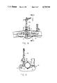
- FIG. 4 is a perspective view of the seed hopper and injection means with portions thereof cut away to more fully illustrate the invention:
- FIG. 5 is a vertical sectional view of the seed hopper and injection means of FIG. 4:
- FIG. 6 is a sectional view of the seed hopper and injection means of FIG. 4 and at a 90° angle to that illustrated in FIG. 5:
- FIG. 7 is an enlarged sectional view seen on lines 7--7 of FIG. 6 with the straight arrows indicating the flow path of the water and seeds and the arcuate arrows indicating the vortex action created within the seed tube:
- FIG. 8 is a partial side view of one of the sprinklers mounted on the auxiliary water line:
- FIG. 9 is a sectional view seen on lines 9--9 of FIG. 8:
- FIG. 10 is a perspective view similar to FIG. 4 but which illustrates a modified form of the injection means:
- FIG. 11 is a partial side view similar to FIG. 2 but which illustrates a modified form of the invention:
- FIG. 12 is a partial top view of the embodiment of FIG. 11.
- the numeral 10 refers to a typical center pivot irrigation system including a main water supply pipe 12 comprised of a plurality of pipe sections 14 joined together and supported by a plurality of drive towers 16.
- Pipe 12 extends outwardly from a center pivot structure 17 including pipe 18 which is connected to a well or water supply 20 or the like by pipe 19 as depicted in FIG. 1.
- Engine 22 operates pump 24 to supply water from the well 20 to the interior of the pipes 18, 19 and 12.
- a plurality of spaced-apart sprinklers 26 are provided on the pipe 12 for sprinkling irrigating water onto the ground 28.
- the drive towers 16 are propelled in conventional fashion so that the system revolves around the center pivot structure 17 to furnish irrigating water to the ground 28.
- An auxiliary water line or pipe 30 is supported on the water supply pipe 12 and extends the length thereof.
- a plurality of tee-connections 32 are imposed in the auxiliary water line 30 as best seen in FIG. 8.
- Each of the connections 32 has a pipe 34 extending upwardly therefrom.
- a remotely operated valve 36 is mounted in the line 34 and has a sprinkler 38 extending upwardly therefrom.
- the valves 36 are electrically connected to a programmable controller to enable the sequential operation of the sprinklers 38 as disclosed in U.S. Pat. No. 3,901,442.
- a water filter 33 and solenoid valve 35 are also provided as seen in FIG. 8.
- auxiliary line 30 is connected by means of a quick coupler 39 to a water line 40 extending from pump 42 which is driven by engine 44.
- the inlet end of pump 42 is connected to a water tank 46 by means of hose 47 as will be described in more detail hereinafter.
- Water line 48 extends from line 19 and has a hydraulically operated valve 52 imposed therein.
- a horizontally extending pipe 58 is positioned in tank 46 which is in fluid communication with the lower end of a tube 60.
- Pipe 58 is connected to hose 47 by means of coupler 59.
- Tube 60 is substantially funnel-shaped comprised of four flat sides 62, 64, 66 and 68. Each of the sides 62, 64, 66 and 68 is provided with an opening 70 formed therein which is offset from the central vertical axis of the tube 60 for a purpose to be described in more detail hereinafter.
- the lower end of tube 60 is provided with an inlet opening 72 which is adjustably selectively closed by an adjustable slide gate valve 74 to control the amount of water entering the lower end of tube 60.
- Float valve assembly 75 is mounted in the interior of the tank 46 for controlling the operation of the hydraulically operated valve 52 to control the supply of water to the interior of the tank 46.
- the numeral 76 refers to a seed hopper adapted to contain the seeds to be planted and which is positioned over the tank 46 and the tube 60 as illustrated in the drawings.
- the lower end of hopper 76 includes a discharge portion 78 having a seed metering plate means 80 rotatably mounted in the lower end thereof.
- Metering plate means 80 has a sprocket 82 connected thereto which is driven by a selectively adjustable gear motor assembly 84 through chain 85.
- the volume of seeds passing from the lower end of the hopper 76 into the tube 60 will depend upon the configuration of the metering plate 80 and the gearing of the sprocket 82 and/or the speed of gear motor 84.
- the drive towers 16 are conventionally operated to propel the system around the center pivot.
- the sprinklers 26 are preferably operated during the seeding operation.
- Engine 22 is operated so that water is pumped from pump 24 into the line 48 and into the interior of the tank 46 through the valve 52.
- Float valve 76 maintains the desired level of water within the tank 46 to prevent the overflow of the tank.
- Pump 42 is operated by means of the motor 44 which draws the water outwardly from the tank 46 through the pipe 58.
- the water in the tank passes into the pipe 58 through the opening 72 and from the tube 60 due to the fact that water can enter the tube 60 through the offset openings 70.
- the offset openings 70 cause the water to swirl within the tube 60, as illustrated in Figure 7, so as to create a vortex action therein so that the seeds dropping into the tube 60 from the metering 80 will pass downwardly into the intake end of pipe 58.
- the metering plate 80 is rotated by means of the gear motor 84 so that the proper amount of seeds are dropped into the tube 60.
- the seeds are suspended in the water and pass through the auxiliary line 30 for discharge through the sprinklers 38.
- the sprinklers 38 are sequentially operated, as the drive towers 16 propel the system over the area to be planted, so that the seeds are substantially uniformly distributed over the area being planted.
- the sequential operation of the sprinklers 38 is necessary since additional seeds must be sprinkled onto the ground at the outer end of the system due to the greater area being covered at the outer end of the system.
- the seeds can be periodically watered by the irrigation system itself.
- the seeds may be planted through the main water supply pipe 12 such as illustrated in FIGS. 11 and 12 by connecting the hose 40' to the pipe 18 so that the seeds suspended in water and passing from the injection means will enter the interior of the main water supply pipe 12 rather than an auxiliary line.
- remotely controlled sprinklers 38' are mounted on the pipe 12 along the length thereof and are operated by a programmable controller to control the sequential operation thereof.
- the system illustrated in FIGS. 11 and 12 is also shown to include small sprinkler heads 26, such may be shut off while seeding or may not be required.
- the metering plate 80 and the gear motor for operating the same may be replaced by a screw auger conveyor 86 which has its inlet end connected to the lower end of the hopper 76 and its discharge end 88 positioned over the tube 60 as best illustrated in FIG. 10.
- Screw auger conveyor 86 is controlled by a variable speed gear motor 90 so that the proper amount of seed is fed to the upper end of the tube 60.
- the water tank 46 may be positioned laterally of the hopper 76.
- the invention herein permits seeds to be planted through a self-propelled irrigation system without the necessity of requiring large equipment to plant the crop thereby eliminating costly labor and equipment expense. Inasmuch as the crop may be planted through the irrigation system, soil compaction is prevented. Perhaps the greatest advantage to the system described herein is that it permits "double cropping" or "intercropping". In other words, a second crop may be planted through the system before the first crop, which had been previously planted, has been harvested. The ability to plant the second crop before harvesting the first crop enables the second crop to be planted much earlier.
- the means described herein is the preferred embodiment and is ideally suited for use with a center-pivot irrigation system, the means of this invention may also be used in combination with a linear move irrigation system.
Abstract
Description
Claims (20)
Priority Applications (1)
| Application Number | Priority Date | Filing Date | Title |
|---|---|---|---|
| US06/919,040 US4729514A (en) | 1985-06-17 | 1986-10-15 | Means for seeding through a center pivot irrigation system |
Applications Claiming Priority (2)
| Application Number | Priority Date | Filing Date | Title |
|---|---|---|---|
| US06/745,183 US4660775A (en) | 1985-06-17 | 1985-06-17 | Means for seeding through a center pivot irrigation system |
| US06/919,040 US4729514A (en) | 1985-06-17 | 1986-10-15 | Means for seeding through a center pivot irrigation system |
Related Parent Applications (1)
| Application Number | Title | Priority Date | Filing Date |
|---|---|---|---|
| US06/745,183 Continuation-In-Part US4660775A (en) | 1985-06-17 | 1985-06-17 | Means for seeding through a center pivot irrigation system |
Publications (1)
| Publication Number | Publication Date |
|---|---|
| US4729514A true US4729514A (en) | 1988-03-08 |
Family
ID=27114414
Family Applications (1)
| Application Number | Title | Priority Date | Filing Date |
|---|---|---|---|
| US06/919,040 Expired - Lifetime US4729514A (en) | 1985-06-17 | 1986-10-15 | Means for seeding through a center pivot irrigation system |
Country Status (1)
| Country | Link |
|---|---|
| US (1) | US4729514A (en) |
Cited By (22)
| Publication number | Priority date | Publication date | Assignee | Title |
|---|---|---|---|---|
| US4949656A (en) * | 1988-02-01 | 1990-08-21 | The Texas A&M University System | Distribution manifold for mobile span-and-tower irrigation systems |
| US5246164A (en) * | 1991-12-16 | 1993-09-21 | Mccann Ian R | Method and apparatus for variable application of irrigation water and chemicals |
| US5278749A (en) * | 1990-01-03 | 1994-01-11 | Heiko De Man | Sprinkler flow control method and apparatus |
| US5628262A (en) * | 1996-06-03 | 1997-05-13 | Nelson; John A. | Interseeding apparatus and method |
| US5884570A (en) * | 1995-09-01 | 1999-03-23 | Lincoln; James A. | Apparatus and method for propagating grass and other living plants using a sod slurry |
| US6007004A (en) * | 1998-09-14 | 1999-12-28 | Valmont Industries, Inc. | Center pivot irrigation system |
| US6029914A (en) * | 1998-09-14 | 2000-02-29 | Valmont Industries, Inc. | Corner irrigation system |
| US6036122A (en) * | 1998-09-15 | 2000-03-14 | Valmont Industries, Inc. | Corner irrigation system |
| US6039273A (en) * | 1998-12-21 | 2000-03-21 | Valmont Industries, Inc. | Corner pivot irrigation machine |
| US6042031A (en) * | 1998-09-14 | 2000-03-28 | Valmont Industries, Inc. | Center pivot irrigation system |
| US6045066A (en) * | 1998-10-01 | 2000-04-04 | Valmont Industries, Inc. | Corner irrigation system |
| US6045065A (en) * | 1998-09-14 | 2000-04-04 | Valmont Industries, Inc. | Method of maintaining a uniform chemical depth under the center pivot portion of a corner irrigation system |
| US6085999A (en) * | 1998-11-18 | 2000-07-11 | Valmont Industries, Inc. | Corner irrigation system |
| AU765287B2 (en) * | 2000-02-01 | 2003-09-11 | Valmont Industries Inc. | A corner pivot irrigation machine |
| US6631585B1 (en) | 2001-01-02 | 2003-10-14 | Marvin J. Williams, Jr. | Intercropping process |
| US8720803B1 (en) * | 2013-06-03 | 2014-05-13 | John S. Standley | Multiple-line irrigation system and method |
| US20140193212A1 (en) * | 2013-01-09 | 2014-07-10 | Cnh America Llc | Seed Inductor Box for an Agricultural Implement Having Multiple Air Paths |
| US20160157445A1 (en) * | 2014-12-05 | 2016-06-09 | Pivot Pup Irrigation, LLC | Irrigating soils and crops |
| US9363956B1 (en) | 2013-06-03 | 2016-06-14 | John S. Standley | Multiple-line irrigation system and method |
| US20160330900A1 (en) * | 2015-05-12 | 2016-11-17 | Double T Equipment Ltd. | Hydroseeder with pivoting auger conveyor |
| CN106922272A (en) * | 2017-04-10 | 2017-07-07 | 京蓝沐禾节水装备有限公司 | Center pivot dragging tube type fertilizer irrigation all-in-one |
| US10070576B2 (en) * | 2013-05-30 | 2018-09-11 | Precision Planting Llc | Seed entraining systems, methods and apparatus |
Citations (42)
| Publication number | Priority date | Publication date | Assignee | Title |
|---|---|---|---|---|
| DE105849C (en) * | ||||
| US952607A (en) * | 1909-10-28 | 1910-03-22 | John D Coplen | Irrigating planter and cultivator. |
| US1208058A (en) * | 1916-01-08 | 1916-12-12 | John M Kuhns | Feeder for water-softening plants. |
| US1324508A (en) * | 1919-12-09 | A corpora | ||
| US1971278A (en) * | 1933-08-21 | 1934-08-21 | Schurmann Henry | Harrow attachment |
| US2682428A (en) * | 1951-12-13 | 1954-06-29 | James E Roberts | Lawn seeder |
| US2746621A (en) * | 1954-12-27 | 1956-05-22 | William J Mcintyre | Seed box loader for grain drills |
| US2754622A (en) * | 1949-04-26 | 1956-07-17 | Rohnert Frederick Waldo | Apparatus for weed killing and seed sowing |
| US2892593A (en) * | 1956-04-30 | 1959-06-30 | Louis P Smeltzer | Ambulant land working and irrigating apparatus |
| US2993626A (en) * | 1958-05-16 | 1961-07-25 | Benjamin T Gildersleeve | Liquid dispenser for seed planters |
| US3110275A (en) * | 1961-03-03 | 1963-11-12 | David W Bonney | Combined planting machine |
| GB953376A (en) * | 1961-07-11 | 1964-03-25 | Raymond Henry Coombes | Plant watering system |
| US3149588A (en) * | 1962-07-31 | 1964-09-22 | Harold E Gatzke | Art of seed-planting |
| US3247812A (en) * | 1963-09-17 | 1966-04-26 | Alfred J Luciano | Apparatus for conditioning lawns |
| US3322080A (en) * | 1965-05-19 | 1967-05-30 | Harold E Gatzke | Method and apparatus for hydraulic seed metering and planting |
| US3326232A (en) * | 1966-04-29 | 1967-06-20 | Otis C Stamps | Fertilizer application and apparatus therefor |
| US3410490A (en) * | 1967-08-01 | 1968-11-12 | W R Wood | Agricultural chemical spraying |
| US3616769A (en) * | 1969-01-20 | 1971-11-02 | William E Normand | Wild oat sprayer attachment |
| US3648631A (en) * | 1968-11-06 | 1972-03-14 | Melvin L Fiedler | Volume displacement seed planter, matrix, and method of planting seed |
| US3648930A (en) * | 1970-10-08 | 1972-03-14 | Irrigation Power Equip Inc | Chemical solution spray system for self-propelled sprinkling apparatus |
| US3653550A (en) * | 1969-01-30 | 1972-04-04 | Church Bruce Inc | Planting method and apparatus |
| US3713404A (en) * | 1971-04-16 | 1973-01-30 | Gen Foods Corp | Plant husbandry |
| US3742877A (en) * | 1970-09-24 | 1973-07-03 | I Coffee | Planter apparatus |
| US3744441A (en) * | 1971-09-27 | 1973-07-10 | Ace Ind | Earth working and planting apparatus and method |
| US3822655A (en) * | 1972-06-05 | 1974-07-09 | Scott & Sons Co O | Lawn conditioning vehicle |
| US3844481A (en) * | 1971-01-22 | 1974-10-29 | D Livingston | Powered mobile spray irrigation for productive crop sewage utilization |
| US3869088A (en) * | 1972-04-24 | 1975-03-04 | Maximilian J Dykmans | Swivel assembly for gunite systems |
| US3895589A (en) * | 1973-09-13 | 1975-07-22 | Cotton Inc | Seed planting apparatus |
| US3901442A (en) * | 1974-08-19 | 1975-08-26 | Valmont Industries | Suspension distribution system |
| US3922977A (en) * | 1973-08-02 | 1975-12-02 | Gen Foods Corp | Plant husbandry |
| US3933309A (en) * | 1975-01-14 | 1976-01-20 | Odegaard Robert J | Spray boom |
| US4145980A (en) * | 1976-12-06 | 1979-03-27 | A. Duda And Sons Inc. | Seeder for planting seeds at precise intervals |
| US4181241A (en) * | 1975-10-08 | 1980-01-01 | National Research Development Corporation | Apparatus for dispensing seeds from liquid suspension |
| US4186671A (en) * | 1974-06-17 | 1980-02-05 | Huang Barney K | Fluid injection soil opener for planters |
| US4224882A (en) * | 1978-02-21 | 1980-09-30 | Cruse John W | Apparatus for sowing seeds in suspension |
| US4244306A (en) * | 1979-08-20 | 1981-01-13 | Idaho Research Foundation, Inc. | Minimum tillage planter |
| US4266489A (en) * | 1980-01-29 | 1981-05-12 | Parramore Emmett W | Double crop planter, sprayer and topper |
| US4277026A (en) * | 1980-02-20 | 1981-07-07 | Garvey Peter M | Liquid chemical spraying apparatus movable by a tower-type water irrigation system |
| US4352463A (en) * | 1979-01-18 | 1982-10-05 | Leisure Lawn, Inc. | Motorized combination wet and dry lawn treatment spreader |
| US4356934A (en) * | 1977-11-18 | 1982-11-02 | Chevron Research Company | Apparatus for spray-treating seeds during planting |
| US4397421A (en) * | 1981-08-10 | 1983-08-09 | Schram Daniel R | Method and means for applying chemicals to a field |
| US4660775A (en) * | 1985-06-17 | 1987-04-28 | Valmont Industries, Inc. | Means for seeding through a center pivot irrigation system |
-
1986
- 1986-10-15 US US06/919,040 patent/US4729514A/en not_active Expired - Lifetime
Patent Citations (42)
| Publication number | Priority date | Publication date | Assignee | Title |
|---|---|---|---|---|
| DE105849C (en) * | ||||
| US1324508A (en) * | 1919-12-09 | A corpora | ||
| US952607A (en) * | 1909-10-28 | 1910-03-22 | John D Coplen | Irrigating planter and cultivator. |
| US1208058A (en) * | 1916-01-08 | 1916-12-12 | John M Kuhns | Feeder for water-softening plants. |
| US1971278A (en) * | 1933-08-21 | 1934-08-21 | Schurmann Henry | Harrow attachment |
| US2754622A (en) * | 1949-04-26 | 1956-07-17 | Rohnert Frederick Waldo | Apparatus for weed killing and seed sowing |
| US2682428A (en) * | 1951-12-13 | 1954-06-29 | James E Roberts | Lawn seeder |
| US2746621A (en) * | 1954-12-27 | 1956-05-22 | William J Mcintyre | Seed box loader for grain drills |
| US2892593A (en) * | 1956-04-30 | 1959-06-30 | Louis P Smeltzer | Ambulant land working and irrigating apparatus |
| US2993626A (en) * | 1958-05-16 | 1961-07-25 | Benjamin T Gildersleeve | Liquid dispenser for seed planters |
| US3110275A (en) * | 1961-03-03 | 1963-11-12 | David W Bonney | Combined planting machine |
| GB953376A (en) * | 1961-07-11 | 1964-03-25 | Raymond Henry Coombes | Plant watering system |
| US3149588A (en) * | 1962-07-31 | 1964-09-22 | Harold E Gatzke | Art of seed-planting |
| US3247812A (en) * | 1963-09-17 | 1966-04-26 | Alfred J Luciano | Apparatus for conditioning lawns |
| US3322080A (en) * | 1965-05-19 | 1967-05-30 | Harold E Gatzke | Method and apparatus for hydraulic seed metering and planting |
| US3326232A (en) * | 1966-04-29 | 1967-06-20 | Otis C Stamps | Fertilizer application and apparatus therefor |
| US3410490A (en) * | 1967-08-01 | 1968-11-12 | W R Wood | Agricultural chemical spraying |
| US3648631A (en) * | 1968-11-06 | 1972-03-14 | Melvin L Fiedler | Volume displacement seed planter, matrix, and method of planting seed |
| US3616769A (en) * | 1969-01-20 | 1971-11-02 | William E Normand | Wild oat sprayer attachment |
| US3653550A (en) * | 1969-01-30 | 1972-04-04 | Church Bruce Inc | Planting method and apparatus |
| US3742877A (en) * | 1970-09-24 | 1973-07-03 | I Coffee | Planter apparatus |
| US3648930A (en) * | 1970-10-08 | 1972-03-14 | Irrigation Power Equip Inc | Chemical solution spray system for self-propelled sprinkling apparatus |
| US3844481A (en) * | 1971-01-22 | 1974-10-29 | D Livingston | Powered mobile spray irrigation for productive crop sewage utilization |
| US3713404A (en) * | 1971-04-16 | 1973-01-30 | Gen Foods Corp | Plant husbandry |
| US3744441A (en) * | 1971-09-27 | 1973-07-10 | Ace Ind | Earth working and planting apparatus and method |
| US3869088A (en) * | 1972-04-24 | 1975-03-04 | Maximilian J Dykmans | Swivel assembly for gunite systems |
| US3822655A (en) * | 1972-06-05 | 1974-07-09 | Scott & Sons Co O | Lawn conditioning vehicle |
| US3922977A (en) * | 1973-08-02 | 1975-12-02 | Gen Foods Corp | Plant husbandry |
| US3895589A (en) * | 1973-09-13 | 1975-07-22 | Cotton Inc | Seed planting apparatus |
| US4186671A (en) * | 1974-06-17 | 1980-02-05 | Huang Barney K | Fluid injection soil opener for planters |
| US3901442A (en) * | 1974-08-19 | 1975-08-26 | Valmont Industries | Suspension distribution system |
| US3933309A (en) * | 1975-01-14 | 1976-01-20 | Odegaard Robert J | Spray boom |
| US4181241A (en) * | 1975-10-08 | 1980-01-01 | National Research Development Corporation | Apparatus for dispensing seeds from liquid suspension |
| US4145980A (en) * | 1976-12-06 | 1979-03-27 | A. Duda And Sons Inc. | Seeder for planting seeds at precise intervals |
| US4356934A (en) * | 1977-11-18 | 1982-11-02 | Chevron Research Company | Apparatus for spray-treating seeds during planting |
| US4224882A (en) * | 1978-02-21 | 1980-09-30 | Cruse John W | Apparatus for sowing seeds in suspension |
| US4352463A (en) * | 1979-01-18 | 1982-10-05 | Leisure Lawn, Inc. | Motorized combination wet and dry lawn treatment spreader |
| US4244306A (en) * | 1979-08-20 | 1981-01-13 | Idaho Research Foundation, Inc. | Minimum tillage planter |
| US4266489A (en) * | 1980-01-29 | 1981-05-12 | Parramore Emmett W | Double crop planter, sprayer and topper |
| US4277026A (en) * | 1980-02-20 | 1981-07-07 | Garvey Peter M | Liquid chemical spraying apparatus movable by a tower-type water irrigation system |
| US4397421A (en) * | 1981-08-10 | 1983-08-09 | Schram Daniel R | Method and means for applying chemicals to a field |
| US4660775A (en) * | 1985-06-17 | 1987-04-28 | Valmont Industries, Inc. | Means for seeding through a center pivot irrigation system |
Cited By (32)
| Publication number | Priority date | Publication date | Assignee | Title |
|---|---|---|---|---|
| US4949656A (en) * | 1988-02-01 | 1990-08-21 | The Texas A&M University System | Distribution manifold for mobile span-and-tower irrigation systems |
| US5278749A (en) * | 1990-01-03 | 1994-01-11 | Heiko De Man | Sprinkler flow control method and apparatus |
| US5452747A (en) * | 1990-01-03 | 1995-09-26 | De Man; Heiko | Sprinkler flow control apparatus and method |
| US5246164A (en) * | 1991-12-16 | 1993-09-21 | Mccann Ian R | Method and apparatus for variable application of irrigation water and chemicals |
| US5884570A (en) * | 1995-09-01 | 1999-03-23 | Lincoln; James A. | Apparatus and method for propagating grass and other living plants using a sod slurry |
| US5628262A (en) * | 1996-06-03 | 1997-05-13 | Nelson; John A. | Interseeding apparatus and method |
| US6045065A (en) * | 1998-09-14 | 2000-04-04 | Valmont Industries, Inc. | Method of maintaining a uniform chemical depth under the center pivot portion of a corner irrigation system |
| US6029914A (en) * | 1998-09-14 | 2000-02-29 | Valmont Industries, Inc. | Corner irrigation system |
| US6042031A (en) * | 1998-09-14 | 2000-03-28 | Valmont Industries, Inc. | Center pivot irrigation system |
| US6007004A (en) * | 1998-09-14 | 1999-12-28 | Valmont Industries, Inc. | Center pivot irrigation system |
| US6036122A (en) * | 1998-09-15 | 2000-03-14 | Valmont Industries, Inc. | Corner irrigation system |
| US6045066A (en) * | 1998-10-01 | 2000-04-04 | Valmont Industries, Inc. | Corner irrigation system |
| US6085999A (en) * | 1998-11-18 | 2000-07-11 | Valmont Industries, Inc. | Corner irrigation system |
| US6039273A (en) * | 1998-12-21 | 2000-03-21 | Valmont Industries, Inc. | Corner pivot irrigation machine |
| AU765287B2 (en) * | 2000-02-01 | 2003-09-11 | Valmont Industries Inc. | A corner pivot irrigation machine |
| US6631585B1 (en) | 2001-01-02 | 2003-10-14 | Marvin J. Williams, Jr. | Intercropping process |
| US20140193212A1 (en) * | 2013-01-09 | 2014-07-10 | Cnh America Llc | Seed Inductor Box for an Agricultural Implement Having Multiple Air Paths |
| US9265190B2 (en) * | 2013-01-09 | 2016-02-23 | Cnh Industrial America Llc | Seed inductor box for an agricultural implement having multiple air paths |
| US10757855B2 (en) | 2013-01-09 | 2020-09-01 | Cnh Industrial America Llc | Seed inductor box for an agricultural implement having multiple air paths |
| US10709056B2 (en) | 2013-01-09 | 2020-07-14 | Cnh Industrial America Llc | Seed inductor box for an agricultural implement having multiple air paths |
| US10709057B2 (en) | 2013-01-09 | 2020-07-14 | Cnh Industrial America Llc | Seed inductor box for an agricultural implement having multiple air paths |
| US10299426B2 (en) | 2013-01-09 | 2019-05-28 | Cnh Industrial America Llc | Seed inductor box for an agricultural implement having multiple air paths |
| US9750177B2 (en) | 2013-01-09 | 2017-09-05 | Cnh Industrial America Llc | Seed inductor box for an agricultural implement having multiple air paths |
| US10070576B2 (en) * | 2013-05-30 | 2018-09-11 | Precision Planting Llc | Seed entraining systems, methods and apparatus |
| US8720803B1 (en) * | 2013-06-03 | 2014-05-13 | John S. Standley | Multiple-line irrigation system and method |
| US9363956B1 (en) | 2013-06-03 | 2016-06-14 | John S. Standley | Multiple-line irrigation system and method |
| US10264740B2 (en) * | 2014-12-05 | 2019-04-23 | Pivot Pup Irrigation, LLC | Irrigating soils and crops |
| US20160157445A1 (en) * | 2014-12-05 | 2016-06-09 | Pivot Pup Irrigation, LLC | Irrigating soils and crops |
| US11284572B2 (en) | 2014-12-05 | 2022-03-29 | Pivot Pup Irrigation, LLC | Irrigating soils and crops |
| US9832923B2 (en) * | 2015-05-12 | 2017-12-05 | Double T. Equipment Ltd. | Hydroseeder with pivoting auger conveyor |
| US20160330900A1 (en) * | 2015-05-12 | 2016-11-17 | Double T Equipment Ltd. | Hydroseeder with pivoting auger conveyor |
| CN106922272A (en) * | 2017-04-10 | 2017-07-07 | 京蓝沐禾节水装备有限公司 | Center pivot dragging tube type fertilizer irrigation all-in-one |
Similar Documents
| Publication | Publication Date | Title |
|---|---|---|
| US4729514A (en) | Means for seeding through a center pivot irrigation system | |
| US4949656A (en) | Distribution manifold for mobile span-and-tower irrigation systems | |
| US5394812A (en) | Injector for polymer placement and a method therefore | |
| US4970973A (en) | Row crop planting apparatus for mobile pipe span-and-tower irrigation systems | |
| US7862254B2 (en) | Underground root margin even irrigation apparatus | |
| US7395769B2 (en) | Individual row rate control of farm implements to adjust the volume of crop inputs across wide implements in irregularly shaped or contour areas of chemical application, planting or seeding | |
| US4660775A (en) | Means for seeding through a center pivot irrigation system | |
| US3302323A (en) | Plant treatment system | |
| WO2013138881A1 (en) | Irrigation systems used in the growing of cotton and wheat | |
| US4300461A (en) | Grass seed planter having fluid injection soil opener | |
| US20050135880A1 (en) | Root zone injection surface irrigation system | |
| CN108781639A (en) | A kind of wheeled delivery structure of orientation seeder | |
| CN209449191U (en) | A kind of precision planter | |
| CN208227969U (en) | Terraced fields automatic irrigation system | |
| US4800826A (en) | Agricultural machine | |
| CN216451905U (en) | Water spring irrigation and drip irrigation common irrigation system for intercropping fruit trees in arid region | |
| EP0040828A1 (en) | Mechanism for irrigation, maintenance and harvesting of farm crops | |
| CN211185156U (en) | Agricultural greenhouse water, fertilizer and pesticide integrated system | |
| CN112273198A (en) | Irrigation equipment for farming | |
| CN219938912U (en) | Soil covering machine for agricultural seedling cultivation | |
| WO2013138878A1 (en) | Irrigation systems used in the growing of corn and soybean | |
| CN114868509B (en) | Liquid fertilizer supply device for vegetable planting and planting method | |
| CN210183992U (en) | Spout medicine and irrigate integration walnut plantation | |
| CN208080143U (en) | A kind of Small Leisure picks the irrigation system of orchard and farm | |
| CN215012955U (en) | Beet planting device capable of automatically applying pesticide |
Legal Events
| Date | Code | Title | Description |
|---|---|---|---|
| AS | Assignment |
Owner name: VALMONT INDUSTRIES, INC., VALLEY, NE 68064 A CORP Free format text: ASSIGNMENT OF ASSIGNORS INTEREST.;ASSIGNORS:OSTROM, CARL R.;CHAPMAN, JOHN A.;REEL/FRAME:004635/0757 Effective date: 19861014 Owner name: VALMONT INDUSTRIES, INC., A CORP OF DE, NEBRASKA Free format text: ASSIGNMENT OF ASSIGNORS INTEREST;ASSIGNORS:OSTROM, CARL R.;CHAPMAN, JOHN A.;REEL/FRAME:004635/0757 Effective date: 19861014 |
|
| STCF | Information on status: patent grant |
Free format text: PATENTED CASE |
|
| FEPP | Fee payment procedure |
Free format text: PAYOR NUMBER ASSIGNED (ORIGINAL EVENT CODE: ASPN); ENTITY STATUS OF PATENT OWNER: LARGE ENTITY |
|
| FPAY | Fee payment |
Year of fee payment: 4 |
|
| REMI | Maintenance fee reminder mailed | ||
| FPAY | Fee payment |
Year of fee payment: 8 |
|
| SULP | Surcharge for late payment | ||
| FPAY | Fee payment |
Year of fee payment: 12 |