US4733401A - Block coding into 24 coordinates and detection of transmitted signals - Google Patents
Block coding into 24 coordinates and detection of transmitted signals Download PDFInfo
- Publication number
- US4733401A US4733401A US06/872,594 US87259486A US4733401A US 4733401 A US4733401 A US 4733401A US 87259486 A US87259486 A US 87259486A US 4733401 A US4733401 A US 4733401A
- Authority
- US
- United States
- Prior art keywords
- coordinates
- mod
- matrix
- odd
- values
- Prior art date
- Legal status (The legal status is an assumption and is not a legal conclusion. Google has not performed a legal analysis and makes no representation as to the accuracy of the status listed.)
- Expired - Fee Related
Links
Images
Classifications
-
- H—ELECTRICITY
- H04—ELECTRIC COMMUNICATION TECHNIQUE
- H04L—TRANSMISSION OF DIGITAL INFORMATION, e.g. TELEGRAPHIC COMMUNICATION
- H04L27/00—Modulated-carrier systems
- H04L27/32—Carrier systems characterised by combinations of two or more of the types covered by groups H04L27/02, H04L27/10, H04L27/18 or H04L27/26
- H04L27/34—Amplitude- and phase-modulated carrier systems, e.g. quadrature-amplitude modulated carrier systems
- H04L27/3405—Modifications of the signal space to increase the efficiency of transmission, e.g. reduction of the bit error rate, bandwidth, or average power
- H04L27/3416—Modifications of the signal space to increase the efficiency of transmission, e.g. reduction of the bit error rate, bandwidth, or average power in which the information is carried by both the individual signal points and the subset to which the individual points belong, e.g. using coset coding, lattice coding, or related schemes
- H04L27/3427—Modifications of the signal space to increase the efficiency of transmission, e.g. reduction of the bit error rate, bandwidth, or average power in which the information is carried by both the individual signal points and the subset to which the individual points belong, e.g. using coset coding, lattice coding, or related schemes in which the constellation is the n - fold Cartesian product of a single underlying two-dimensional constellation
Definitions
- This invention relates to means and a method of signalling binary or other numeric data on a communications channel.
- the means and method encode blocks of b units of data into 24 coordinate signal values which 24 coordinate values are then modulated on a carrier by whatever modulation is desired.
- the means and method of the invention also extend to the detection and decoding at the receiver end of the channel.
- the invention particularly relates to a novel means and method of detecting the 24 coordinates after transmission and demodulation but before decoding.
- the overall encoding, detecting and decoding means utilizes the fact that 24 independent signal values may be treated as the coordinates of a point in 24 dimensions.
- Signal structures in 24 dimensional space provide performance that is superior to other dimensional signal structures investigated.
- the superiority may be realized in terms of fewer errors at a given signalling rate or in terms of a higher signalling rate for a given statistical possibility of error.
- a ⁇ message point ⁇ is the point in 24 dimensions defined by the 24 coordinates.
- ⁇ message point ⁇ is not only used for points in 24 dimensions which are used for signalling but also for points in lesser dimensions.
- a message point in H dimensions may be identified by the combination of a message point in F dimensions and a message point in G dimensions where F+G equal H.
- the signalling is of message points in 24 dimensions
- the term message point applies to points in less than 24 dimensions which are not signalled per se but which are used in algorithms related to encoding or decoding the 24 dimensional message point signalled. It may help with following the terminology herein to note that, in higher dimensions than one, a number of coordinates equal to the dimension is required to define a message point. In one dimension the coordinate is also the message point.
- signalling speed is related to the number of bits which may be encoded per block.
- a look-up table may be used for small values of b. However, the number of entires in such look up table varies as 2 b so that for large values of b the requirements would exceed the capacity of known computer or microprocessor look up tables.
- This invention provides means and a method for deriving the coordinates in 24 dimensions to identify individual blocks of b digits.
- algorithms are provided which allow the conversion of each block of b digits into message point coordinates in 24 space which coordinates uniquely define the block of b digits represented.
- message points defined by 24 coordinates may be considered as located in concentric shells about the origin (the point which has 24 0 values for coordinates) or about another datum defined by 24 coordinates.
- a shell therefore contains those message points where ##EQU1## is the same value where C1, C2, . . . C24 are the coordinates of the message point and CD1, CD2, . . . CD24 are the coordinates of the datum.
- the invention generally provide means and method which involves treating each block of b bits as a number N which identifies the sequence of bits in the block.
- N is the binary number represented by the sequence of bits in the block.
- the invention herein uses 24 coordinates encoded in accord with a Leech matrix.
- a Leech matrix has a classical 12 ⁇ 24 form as demonstrated in Table 1 below:
- modulo 2 By adding all possible combination of rows of the Leech matrix column by column, modulo 2, ( ⁇ modulo ⁇ is often abbreviated to ⁇ mod ⁇ herein) it is possible to produce 4096 unique 24 series of 0 and 1 values known as pattern vectors.
- An example the pattern vectors for the mod 2 sums for 0 rows and rows 1, 2, 3 are:
- the 24 coordinates must be all even or all odd.
- good packing or relation to modulated communication signals is meant (a) that for given signalling power the message point defined by the 24 coordinates can have a relatively good chance (the best for known 24 space packing and better than other space packings) of being distinguished from the adjacent message points or, conversely (b) that one can use less power and have statistically a change of being distinguished from message points using other packings in 24 or other dimensions.
- the lattice of message points whose coordinates are all 0 mod 4 are centred about the point whose 24 coordinates are 0's and is related to the pattern vector with zeros in each of the 24 places.
- This lattice is known as the Z lattice.
- the remaining 4095 even and 4096 odd lattices are known as co-sets of the Z lattice are each respectively identified with one of the 4096 pattern vectors, and are reached by modifications of points on the Z lattice as hereinafter described.
- the good packing is obtained with the Leech matrix by producing 24 coordinates on the Z lattice for modification in accord with a selected pattern vector.
- the modification is (when even coordinates are selected) to alter the Z lattice coordinates by 0 or 2 in the same sense depending on whether the selected pattern vector has a 1 or a 0 (and either but not both conventions may be used); and (when odd coordinates are selected) to alter the lattice coordinates by 1 in opposite senses depending on whether the selected pattern vector has a 1 or a 0 (and either but not both conventions may be used).
- odd coordinates to maintain the modulo sum rule one coordinate must be increased or decreased by 3 instead of 1).
- a block of data bits may be converted into a number N.
- the number N is identified by the Leech pattern vector and whether consisting of even or odd coordinates together with a series of 24 coordinates. Selection of the vector and the choice of even or odd coordinates allows N to be divided by 8192 to give a quotient M and a remainder C.
- the quotient M is encoded as coordinates on the Z lattice (the lattice built upon the point whose coordinates are all 0's) as hereinafter described while twelve bits of C are used to selected the pattern vector to modify the Z lattice coordinates, and one bit of C indicates the selection of even or odd.
- the coordinates thus selected are converted to signals, modulated on a carrier and transmitted.
- This invention relates to the detection of 24 coordinate signals encoded as before described which utilizes a novel system of detecting at the receiver the pattern vector used in the transmission.
- the novel method of detection requires a (relatively) small number of decoding steps.
- the same 4096 pattern vectors which are developed from the conventional Leech matrix, may be developed from any matrix referred to as a ⁇ modified Leech matrix ⁇ or ⁇ modified matrix ⁇ derived from the conventional matrix, Table 1, by combinations of its rows added coordinate by coordinate mod 2, care being taken that the selection is such that the modified matrix will allow the development of the 4096 unique vectors.
- the conventional or a modified Leech matrix may be modified by interchanging any whole columns. This will, of course, have the effect of correspondingly interchanging the pattern vector places and the effect on individual coordinates. This will not change the process described as long as the same matrix form is used both in encoding and decoding.
- the conventional Leech lattice has its columns interchanged and new rows made by the summation mod 2 of old rows (as referred to above and described in detail hereafter) to produce the matrix:
- the modified matrix is then used in encoding by having the dictates of pattern vectors derived therefrom superposed on Z lattice coordinates.
- the modified coordinates are modulated on a carrier and transmitted.
- the received transmission is demodulated and detected in accord with the preferred method and means disclosed herein.
- the coordinates are then decoded to recover the number M and therefrom the number N by use of the number C.
- the preferred method of detection makes use of the modified matrix, to detect the selected pattern vector used and even or odd. These of course are used to produce the Z lattice coordinates used.
- the invention is described in relation to encoding, modulation and transmission at the transmitter and reception demodulation detection and decoding at the receiver. Thereafter the preferred encode, detection and decode algorithms are set out.
- the number of bits or of other numerical data is converted to the number N. This number is divided by 8196 to provide a quotient M and a remainder C.
- the 13 bits of remainder C identify the pattern vector of the modified Leech matrix and whether the coordinates will be even or odd.
- a table is provided listing the numbers (not the coordinates) of suitable message points for a sequence of shells in 24 dimensions. The means provided determines the shell in the sequence whereat the total available points in the sequence is greatest without exceeding M.
- the value X 24 being M less the number of points in the sequence, identifies (without locating) a point in the next succeeding shell in the sequence which will define M.
- 24 corresponding values of the value X 24 in 1 dimension may be derived, the 24 one dimensional value identifying the value and sign of the coordinates C1, C2 . . . C24 which define the message point. These coordinates may then be modulated on the carrier.
- the demodulated and detected coordinates are subjected to a combining algorithm which is basically the reverse of the splitting algorithm and which allows the reconstruction of the number X 24 and the shell in 24 dimensions from the coordinates, and from that the numbers M and C (derived from the detection of the pattern vector and of whether even or odd was used) giving the number N and the block of b bits.
- splitting algorithms at the transmitter and of combining algorithms at the receiver avoid the use of large look up tables in converting the number M, identifying the block of b digits, to 24 message point coordinates for signalling and vice versa. Since look up tables of the required capacity are not available, the use of the splitting and combining algorithms allows signalling at speeds higher than previously.
- Tables may be built up for use with the splitting algorithm beginning with the number of coordinates in 1 dimension which satisfy the coordinate requirements for signalling in 24 dimensions. These numbers are tabulated. It is found most convenient to tabulate these numbers using the concept of shells where each shell is numbered from 0 in regular intervals, each unit interval corresponding to an increase in the square of the radial distance, r 2 from the origin or datum in one dimension, by the square of the permissible interval between coordinates, the latter being used in integral form in most applications.
- the coordinates are integers and must be all even or all odd. If all even the sum of the coordinate in the signalling dimension must be 0 modulo 8 and if all odd the sum of the coordinates must be 4 modulo 8.
- the permissible coordinate interval is 4 and one (of 4096) pattern vectors provides such coordinates centred at the origin. The points on shells centered about the origin are contained on what is known as the "Z lattice". Accordingly, in one dimension, the table of permissible values* tabulated by shells is:
- the available message points in 2 dimensions may be derived using the summing algorithm ##EQU2## where n is the shell number, where the number of dimensions F plus the number of dimensions G equals the number of dimensions H; where V H , V F , V G are the number of available (i.e. satisfying the coordinate requirements) points in H, F, G dimensions respectively and the intervals of I are constant and chosen to ensure that the sum includes all such available points up to n times the square of the interval.
- I indicates the shell number in dimension F while n-I (often referred to as J) is the shell number in dimension G.
- the available points in 24 D for the Z lattice may be determined.
- Tables of numbers of available coordinate values for dimensions 1, 2, 4, 6, 12, 24 for an origin centred ( ⁇ Z ⁇ ) lattice with intervals of 4 between coordinates are set out in tables Z1, Z2, Z4, Z6, Z12, ⁇ Offset ⁇ attached to the algorithms herein.
- the Z24 ⁇ Offset ⁇ table does not include the points which, although derived from the Z12 tables in accord with the algorithm, do not satisfy the modulo rules for the coordinate sum, even through such points would have been indicated by the algorithm.
- table Z24 omits the points which the algorithm would have provided for odd numbered shells, since these would not have satisfied the modulo sum rule that the coordinates must be zero modulo 8 (where the coordinates are all even as in the Z lattice).
- the coordinates are determined on the Z lattice and modified in accord with the selection of a pattern vector and of even or odd coordinates.
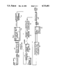
- FIG. 1 shows schematically the overall circuitry employed with this invention including the program instructions and algorithms employed therewith,
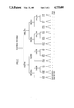
- FIG. 2 shows the relationship of sequential uses of the splitting and combining algorithm.
- FIG. 1 schematically illustrates the functional operations performed in a communications system utilizing the invention.
- the functional operations are not intended to imply particular hardware or choices between hardware and software modes, except in blocks 20, 80 and 90.
- block 20 and block 90 the microprocessors are programmed to perform the operation indicated.
- microprocessors are specified for use in various steps of the operation, the operation described may use any system adapted to provide the claimed means and methods.
- serial binary data in blocks of b bits is scrambled at scrambler 15 and converted at serial to parallel convertor 10 into groups of b bits.
- the data to be transmitted in one frame consists of 96 bits to be block encoded and if an auxiliary 200 bps channel is desired 97 bits must be block encoded.
- blocks of 85 bits must be encoded per block and at 14,400 bits per second, 73 bits must be encoded per block.
- the groups of b bits are block encoded at block 20 into the values of 24 coordinates C1, C2, . . . C24 in accord with the encoding algorithm hereinafter provided.
- the values of the coordinates are converted to modulating signals in coordinate signal generate 30.
- the outputs of coordinate signal generator 30 and carrier generator 40 are converted at modulator 45 into a carrier modulated in accord with the values C1, C2, . . . C24.
- the invention is independent of the method of modulation. It will usually be preferred to use Quadrature Amplitude modulation QAM wherein the signals incorporating the coordinate values are modulated in twelve pairs by conventional quadrature methods. Several other forms of modulation are available.
- DSB-QAM double side band-quadrature modulation
- modulation techniques such as phase-shift keying PSK, quadrature amplitude modulation (QAM), already referred to, and combined amplitude and phase modulation which have long been known in the art.
- the modulated carrier signals from modulator 45 are provided to transmitter interface 50 and transmitted in the interfaced form to the channel. After reception from the channel at receiver interface 60 the received signals are demodulated, conditioned and equalized at block 70, all in accord with techniques well known to those skilled in the art.
- the output of block 70 is provided to the microprocessor detector and decoder 80 where by combined operation of the microprocessor and the detection method, the Leech pattern vector used and the transmitted coordinates C1, C2, . . . C24 are detected.
- the matrix in accord with the detection and decoding algorithms to be described converts these coordinates into the b bits of binary data which were supplied to the input of block 20 at the receiver.
- the reconstituted b bits are converted to serial binary data at convertor 90.
- the pattern matrix shown is not the classical form but is derived therefrom where each row of the pattern matrix is derived from a different combination (added coordinate by coordinate modulo 2) of the rows of the classical form including the corresponding row.
- the conventional Leech Matrix is shown below:
- the columns of the above matrix are rearranged into the sequence.
- the Pattern Matrix provides 4096 pattern vectors and coordinates modified by each of these patterns may be even or odd
- the number N which identifies the bit sequence in the block of b bits is divided by 8192 to provide a quotient M and a remainder C.
- the quotient M will be encoded to 24 coordinates of a message point on the Z lattice and, after such encoding, the coordinates will be modified in accord with the selected pattern vector and the choice of even or odd coordinates, both being determined by the number C.
- Z tables are provided for dimension 1, 2, 4, 6, 12 and 24.
- Each dimension table called Z1, Z2, Z4, etc., tabulates for shell number the number of points which satisfy the coordinate rules (the coordinate modulo sum rules are not considered except in 24 dimension).
- the shell number in each table is 1/16 the square of the radius (r 2 ) measured from the origin, in the dimension being considered, to each of the set of coordinates making up the entry for that shell number.
- the Z24 table which is the basis for the ⁇ Offset Table ⁇ used with the encode, detect, decode algorithms, does not include the values for the odd shell numbers, which the above algorithm would provide, since such the coordinates of points on such odd numbered shells will not satisfy the 0 modulo 8 requirements of the coordinate sum for 24 dimensions (all even coordinates) and
- the Offset Table provides, for each even shell number, the total number of points on the previous shells in the sequence defined by the shell table.
- the value D which identifies a point on the selected 24 dimensional shell is used to derive first number X 12 (F) on a first 12D shell and a second number X 12 (G) on a second 12D shell.
- first number X 12 (F) on a first 12D shell and a second number X 12 (G) on a second 12D shell is used to derive first number X 12 (F) on a first 12D shell and a second number X 12 (G) on a second 12D shell.
- the 24 derived Z lattice coordinates define a point on the Z lattice defining quotient M.
- the coordinates are then modified in accord with a pattern vector derived from the modified leech lattice to take into account the value C.
- Even or odd coordinates are selected in accord with whether C is even or odd, 12 higher binary places of C define a number from 0 to 4095 which is used to select one of the 4096 pattern vectors.
- the coordinates are then modified as follows: (1) If C is odd, subtract 3 from the first of the 24 lattice point coordinates if the first bit of the pattern vector is a zero or add 3 if it is a one.
- a point defined as number D on a shell S24 in 24 space may be also defined by number R12A on shell S12A in 12 dimensional space together with number R12G shell S12G in 12 dimensional space.
- Each number and shell in 12 dimensional space may be identified by a pair of number and shell combinations in 6 dimensional space, and so on.
- the ⁇ tree ⁇ of operations of the splitting algorithm is indicated by downward travel in FIG. 2.
- the algorithm relates to signalling using 24 message point coordinates. Since there are 4096 lattice centres and each may be used with 24 coordinates with the choice of making them all even or all odd the number N identifying the bit sequence in a block of b bits is divided by 8192 producing a quotient M and a remainder or coset point C.
- the designation D (X 24 ) refers to the general discussion where ⁇ X K ⁇ designates a point on a shell in K space and the designation D is used for X 24 in the algorithm to follow.
- ⁇ * ⁇ represents the multiplication operation or ⁇ x ⁇ .
- step 4 of the splitting algorithm ⁇ X ⁇ is divided "by entry I of table A". It will be appreciated that what is happening here is that the number X is to be assigned to two shells is being divided by entry I representing the first assigned shell's capacity of available points, to obtain a quotient Q to be assigned to the second assigned shell and a remainder (R), to be assigned to the first assigned shell. Obviously the roles can be reversed and division may be performed by the entry for second shell to obtain a quotient to be assigned to the first and a remainder to the second. This is equivalent to the procedure outlined if a corresponding complementary operation is performed at the decoder.
- sequence of shells represented by the offset table need not be in the order of rising shell number although this appears the most convenient for programming.
- the tables Z1-Z12 should be in order of rising shell number for convenience and simplicity in programming.
- the signal transmitted from the transmitter channel interface 50 on the channel is received at the receiver channel interface 60.
- the signals received are subjected to conditioning, demodulation and equalization at block 70, all blocks 15,10,30,40,45,50,60,70,90 and 100 and being designed and operated in accord with techniques well known to those skilled in the art.
- the conditioned, demodulated and equalized signals having the values C1-1/2, C2-2 . . . C24-1/2 are supplied to the detector 80 shown in FIG. 2 and described in the programming instructions for the detection algorithm described hereafter. The following comments on the detection algorithm programming steps, should be read therewith.
- the transmitted coordinates which have been encoded and modulated at the transmitter are, at the receiver, demodulated.
- the demodulated received values have 1/2 added to compensate for the deduction in step 32 of the encoding algorithm.
- the received values each augmented by 1/2 are stored. Also stored are their values mod 4 (detection algorithm step 2), and mod 8.
- the detection algorithm is based on the following derivation from the conventional Leech matrix. It may be noted that the Leech matrix becomes an equivalent matrix and produces the Z and coset lattices with any different sequence of coordinates and furthermore any rows may be replaced by the addition of mod 2 of other rows as long as all rows are represented as components of sums in the final matrix to avoid a singular matrix.
- the following form may be obtained from the conventional Leech matrix by re-arranging the columns into the sequence: (numbers are of conventional matrix columns) 1,18,24,22,19,10,23,3/6,8,21,16,12,15,17,7,/9,13,2,4,12,5,20, 11. Th strikes indicate the division between octuples.
- the essential features of this form are: that the first three rows have all zeros in two of the three octuples and all ones in the other octuple (in successively the first, second and third octuples). the next three rows have two identical octuples followed by eight zeros and the next three rows have eight zeros followed by two of these same 8-tuples. The final three rows each consist of three identical 8-tuples.
- Any subset of rows of the above matrix may be selected and exclusive ored together (i.e. summed modulo 2) to produce one of 4096 possible pattern vectors.
- They may be 24 even integers which are 0 mod 4 where a pattern vector has a 0 and 2 mod 4 where the same pattern vector has a 1 and the sum of the coordinates is 0 mod 8.
- the "detection problem” is: Given an arbitrary point in 24-space as represented by 24 given coordinates, determine the pattern vector used and the choice of odd or even coordinates associated with the Z or co-set lattice point closest to the given point.
- the essential feature of this detection method may be seen by noting:
- rows 4 to 12 produce only 512 patterns which may be divided into 64 groups of 8 where the members of a group differ only by the choice of rows 4, 5 and 6.
- columns in the Leech matrix used may be interchanged as long as the same conversion is used at transmitter and receiver as performed in the preferred embodiment, or in an alternate method in accord with the invention at the beginning and end of the pattern vector detection process.
- the alternate method it will be noted that one version of the matrix can be used during encoding, modulating transmission and initial reception and demodulation. After demodulation the places of the coordinates may be interchanged to render detection easier. This has, at this stage, (since the characteristics of a pattern vector are impressed upon the coordinate values), the same effect as the interchanging of matrix columns before the pattern vector is selected.
- the coordinates and the pattern vector values may have their order returned to that transmitted and originally received, for further processing.
- the 24 coordinates representing a block encoded group of bits have been chosen at the transmitter (a) to satisfy the individual coordinate modulo rules and the coordinate sum modulo rules and (b) for modification in accord with a particular Leech pattern vector; and (c) whether they are to be all even or all odd.
- Such modified coordinates are modulated on a carrier and transmitted.
- Such modulation, whatever they type used, is usually in accord with a quadrature system and under such system the coordinates are modulated on the carrier in pairs.
- the detected signals are demodulated and the received values of the coordinates stored.
- Such received coordinates differ from those transmitted due to the effects of distortion, noise, and other causes during modulation, encoding and transmission and the problem of detection is, of course, to determine the pattern vector used and the actual coordinates encoded.
- X n is C n mod 4.
- X n is composed of I n , an integral and F n , a fractional part. It will be noted that, (since X n is calculated mod 4) the value I n , may be 0, 1, 2, 3. k is the possible transmitted value of I n and likewise varies through 0, 1, 2, 3.
- a table (Table 1) is provided having, for each value I n , the four values of k. For each of such combinations there is calculated:
- M n ,k a measure of the square of the distance from X n to k, a ⁇ measure of the error ⁇
- P n ,k a positive measure of the difference of squared distance M n ,k and the squared distance from X n to the closer of k+4, k-4.
- P n ,k represents the penalty or increase in the value M n ,k if the closer of k+4 or k-4 has later to be substituted for k to achieve the modulo sum rules for 24 coordinates.
- B n ,k is an 0 or 1 value designed to give, for each of the 24 coordinates, an indication of the effect of the coordinate on the modulo sum requirements. If I n mod 4 does not equal the integral value of C n mod 8 then the value for B n in Table 1 must be complemented.
- Table 2 contains 128 pairs k1,k2 of octuple groups (j) of coordinates modulo 4. In each pair the two octuples are complements, that is, for even pairs, the 2's and 0's are interchanged and, for odd pairs the 1's and 3's are interchanged.
- Penalty values must be assembled in case of the necessity for a ⁇ flip ⁇ .
- the term ⁇ flip ⁇ refers to the situation where the 24 mod 4 coordinate total does not satisfy the coordinate sum modulo 8 rule, and it is necessary to find the change of k to k+4 or k-4 or alternate change that will cause the smallest increase in GH g ,j such increase being the smallest penalty P n ,k.
- the sum SUM 1 of the M n ,k1 values is compared with the sum SUM 2 of the M n ,k2 values and the smaller designated GM g ,j.
- Table 3 values are expressed in base 8 (octal) values for brevity. Thus each octal digit corresponds to three consecutive binary digits.
- each group of eight may be determined by summing corresponding to only the first two octuples j1,j2. Adding the third octuple is unnecessary because, for any row group of eight j3 is the same for each member of the group. If, instead of rows 4, 5 and 6, the rows 10, 11 and 12 had been used to determine the components of the eight row sets of table 3, j3 would have been different for each row set and the winner of the row set would have had to be determined by summing j1, j2, j3 for each row in the set.
- each sum GM n ,1 +GM n ,2 is added the GM n ,3 as determined by the Gm n ,j3 of the j3 of the table.
- the B n ,1 +B n ,2 +B n ,3 values are similarly summed (mod 2). If the modulo sum, as indicated by the summed B values, is incorrect then the coordinate lowest GP n ,j is added with or without the substitution of a complementary octuple as previously described.
- the GM g ,j, GP g ,j, GB g ,j, RN g ,j, RF g ,j for the 128 pair winners are identified with the corresponding "j" value of Table 2. It will be noted that for any of the three possible octuples (mod 4) making up the 24 coordinates, one of two choices has been eliminated in step 2 and this result is the equivalent of 3 bits of information of the 13 required, (that is the twelve bits to identify the pattern vector and one to identify whether even or odd coordinates have been chosen).
- row k 2 is the obvious complement of k 1 it will be noted that k 2 will have a lower G m when rows 1, 2, 3 of the modified Leech matrix have been used for (what turns out to be) the first octuple, second octuple and third octuple respectively, since the eight 1's in the matrix octuple will (mod 2 addition) produce the complement.
- these k 1 v k 2 candidates in the three octuples in the final result will provide the first three bits of the row determinant.
- the ⁇ row determinant ⁇ is the series of 12 binary digits which determines which of the rows of the Leech or modified Leech matrix are summed, mod 2 to produce the pattern vector.
- the row determinant 010 010 010 010 states that the second, fifth, eighth and eleventh rows of the modified Leech matrix should be added mod 2 to produce the pattern vector.
- Table 3 gives the 512 possible combinations of the first two octuples j1, j2 in pattern vectors derived from a modified Leech matrix. Actually Table 3 gives 256 values which are doubled by considering there is a further table differing from the first only in that a 1 is added before each j1, j2 (and j3 in a later step).
- j1, j2, j3 are binary digits. However for compactness herein these j values are expressed in octal notation and each octal digit represents three successive binary digits.
- rows 4, 5 and 6 in the mod 2 sum is determined by the three bits which are set out above and the order would normally be reversed to place the bits indicating use of rows 4,5 and 6 in places 4,5 and 6 respectively, of the row determinant.
- the seventh to ninth places of the row determinant may be chosen to indicate the presence or absence of rows 7,8 or 9 in the modulo 2 sum.
- the middle octal digit represents the extent of usage of rows 10,11,12 of the modified matrix.
- the middle octal digit determines the inclusion of rows 10,11 and 12 as follows:
- the tenth to twelfth places of the row determinant may be chosen to indicate the presence or absence of rows 10,11 or 12 in the modulo 2 sum.
- the first number of any j that is the added 1 or 0 of "the best of 128" winner will determine even or odd.
- bits in the row determinant and hence (if the bit is one) the use of the corresponding rows in the mod 2 sums are determined as follows (left to right):
- M n ,k, P n ,k and B n ,k etc. become M(n,k) P(n,k) and B(n,k) etc.
- the determination of the pattern vector corresponds to step 5 of the detect algorithm.
- steps 6-8 the row determinant represented by the first twelve places of C is used to determine the pattern vector which is used (steps 7 or 8) to modify the detected coordinates (full not mod values) to reverse the modification in accord with the same pattern vector at the encoder.
- Step 9 alter stored coordinate value corresponding to a flipped coordinate.
- the 1D Z lattice points S1(1), R1(1); S1(2) R1(2) . . . S1(24) R1(24) are combined by the combining algorithms to determine the encoded number Z.
- the combining algorithm reverses each of the steps of the splitting algorithm.
- the combining algorithm is further used to reverse the dimensional steps represented by the tree of FIG. 2 to produce the value D,S24 from the 24 S1, R1 values.
- I k is multiplied by the quotient Q and R is added to produce the "last X" of the splitting algorithm.
- the result of the combining algorithm is to produce the number X H and the shell number in dimension H having started with two pairs of values X F and shell no in dimension F and, X G and shell no in dimension G.
- the shell number gives the offset value for addition to D, to give the encoded sum Z.
- Z is multiplied by 8192 reversing the division at the encoder.
- the value N is then transmitted as b bits from microprocessor 90 to parallel to series convertor 100 were it is converted to serial binary bits. Assuming that scrambling was performed at scrambler 15 than the serial binary bits are unscrambled at uncrambler 95 into unscrambled serial binary bits of serial binary data.
- X 24 identifies a message point or a shell in 24 dimensions. X 24 corresponds to D in step 3 of the encoding algorithm and step 24 of the decoding algorithm.
- the data to be transmitted in one frame consists of 96 bits which may be considered as a number, N, in the range from 0 to 79,228,162,514,264,337,593,543,950,335. If an auxillary 200 bps channel is desired, the number of bits is increased to 97 so that N is from 0 to 158,456,325,028,528,675,187,087,900,671. At 16,800 bits per second with an auxillary channel, only 85 bits are required which may be considered as a number, N, in the range from 0 to 38,685,626,227,668,133,590,597,631.
- N may be converted to a group of 24 coordinates to be transmitted by the following algorithm.
- Step 1 Divide N by 8192. Let the quotient be M and the remainder be C. M will now be encoded into a point in the Z lattice and C will be used to select a coset point.
- Step 2 Scan the offset table (table 1) to find the entry for which the value in the offset column is as large as possible but does not exceed M. Let S be the corresponding shell number.
- Step 3 Subtract the value in the offset column from Z giving a difference D. So far we have selected a shell corresponding to the table entry and we will use the value of D to select a message point from within this shell.
- Step 28 The 12 high order bits of the 13 bit binary representation of C are associated with the twelve rows of the pattern matrix with the most significant bit associated with the first row.
- the 12 high order bits of C constitute the row determinant.
- Step 29 Exclusive or together those rows of the matrix for which the associated bit of C is a one to produce a "pattern vector" of 24 bits.
- Step 30 If C is even, add 2 to each Z lattice point coordinate for which the corresponding pattern vector bit is a one.
- Step 31 If C is odd, subtract 3 from the first Z lattice point coordinate if the first bit of the pattern vector is a zero or add 3 if it is a one. For the remaining 23 Z lattice point coordinates, add 1 if the corresponding pattern bit is a zero or subtract one if it is a one.
- Step 32 Subtract 1/2 from each coordinate to remove the statistical bias introduced in step 30. The coordinates are now ready for transmission.
- Step 2 Multiply entry I of table A by entry J of table B to produce a product, P.
- Step 3 If P is less than or equal to X, Subtract P from X (the difference is a new X). Add 1 to I, Subtract 1 from J and return to step 2. If P is greater than X, continue to step 4.
- Step 4 Divide last X by last entry I of table A to produce a quotient, Q and a remainder R.
- the splitting algorithm is now complete.
- the detection algorithm proceeds as follows:
- Step 1 Add 1/2 to each coordinate to compensate for the subtraction performed in the transmitter.
- PEN1 PEN1+SUM1-GM(g,j)
- PEN2 PEN2+SUM2-GM(g,j) (Note the one of SUM1-GM(g,j) or SUM2-GM(g,j) must be zero)
- TEMP the absolute value of the difference between SUM1 and SUM2 and compare this with GP(g,j) as computed above. If TEMP is smaller, replace GP(g,j) with TEMP and replace RF(g,j) with RN(g,j)+1 (modulo 2). Any GP(g,j) replaced in this way should be marked as "special"
- Step 4 Each row of table 3 contains a value of j3 followed by eight entries each giving a value of j1, j2 and a 9 bit octal value headed "bits".
- table 3 to be doubled in size with a leading 0 appended to each of the values of j in the first (even) half and with a leading 1 appended to each of the values of j in the second (odd) half.
- the smallest of the 128 row winners identifies the final result. If the winning sum did not include a GP(g,j) term the output bits are RN(1,J1), RN(2,j2), RN(3,j3) followed by the nine bits from the "bits" column of the selected entry of the winning row followed by a 0 if the winner was even or a 1 if odd. If a GP(g,j) term was included in the winner, one of RF(1,j1), RF(2,j2) or RF(3,j3) must replace one of RN(1,j1), RN(2,j2) or RN(3,j3) depending on which of GP(1,j1), GP(2,j2) and GP(3,j3) was smallest. Of these 13 bits, the first 12 define the matrix rows used and the last defines odd/even. These 13 bits comprise the number C.
- Step 5 The 12 high order bits of the 13 bit binary representation of C are associated with the twelve rows of the pattern matrix with the most significant bit associated with the first row. These 12 high order bits constitute the row determinant.
- Step 6 Exclusive or together those rows of the matrix for which the associated bit of C is a one to produce a "pattern vector" of 24 bits.
- Step 7 If C is even, subtract 2 from each detected coordinate C1, C2 . . . C24 for which the corresponding pattern vector bit is a one.
- Step 8 If C is odd, add 3 to the first detected coordinate C1 if the first bit of the pattern vector is a zero or subtract 3 if it is a one. For the remaining 23 detected coordinates C2, C3 . . . C24, subtract 1 if the corresponding pattern bit is a zero or add 1 if it is a one.
- Step 10 Round each coordinate to the nearest 0 mod 4 value. A coordinate which is exactly 2 mod 4 should be rounded up. The 24 coordinates are now those of the Z lattice point.
- Step 25 Scan the offset table (table 1) to find the entry for shell S. Add the value in the offset column to D giving a sum M.
- Step 26 Multiply M by 8192 and add C. The result is the value of N.
- Step 1 Multiply Q by entry I of table A and add R to produce X.
- modified Leech matrix involves both column rearranging and row conversions of the conventional Leech matrix.
- novel detection means and method with encoder matrices of the form of the Conventional Leech matrix or derived therefrom (or otherwise using a column arrangement different from that of the modified matrix) column changes used for the new matrix.
- Such matrices are designated here DC matrices for brevity.
- Encoding is performed in accord with the DC matrix and this is modulated and transmitted to the receiver. After demodulation the column arrangement is altered to conform to that of a Modified Leech matrix.
- the newly placed received coordinates are then subjected to the detection algorithms steps 1 to 5 as described herein. With the 13 bits derived it is now necessary to take into account any difference in row conversion.
- This may be done by mapping the 13 derived bits into a new 13 bits in accord with the use of a 13 ⁇ 13 binary matrix by techniques well known to those skilled in the art.
- rows of the modified matrix may be sumed mod 2 to indicate the pattern vector with the modified matrix place order.
- pattern vector it is possible to do one of two things: (a) to modify the stored altered place coordinate values in accord with steps 7 & 8 and then reverse the alterations in the coordinate places to produce the order used at the transmitter, then continuing with step 9 of the detection algorithm; or (b) reversing the alterations in the places of the pattern vector and using the reversed alteration pattern vector to modify the coordinates as received before alternation then continuing with step 6.
- ⁇ mod ⁇ is used as an abbreviation for ⁇ modulo ⁇ herein.
Abstract
______________________________________
Description
______________________________________
Row No.
______________________________________
1        1 0 0 0 0 0 0 0 0 0 0 0 0 1 1 1 1 1 1 1 1 1 1 1
2        0 1 0 0 0 0 0 0 0 0 0 0 1 1 0 1 0 0 0 1 1 1 0 1
3        0 0 1 0 0 0 0 0 0 0 0 0 1 0 1 0 0 0 1 1 1 0 1 1
4        0 0 0 1 0 0 0 0 0 0 0 0 1 1 0 0 0 1 1 1 0 1 1 0
5        0 0 0 0 1 0 0 0 0 0 0 0 1 0 0 0 1 1 1 0 1 1 0 1
6        0 0 0 0 0 1 0 0 0 0 0 0 1 0 0 1 1 1 0 1 1 0 1 0
7        0 0 0 0 0 0 1 0 0 0 0 0 1 0 1 1 1 0 1 1 0 1 0 0
8        0 0 0 0 0 0 0 1 0 0 0 0 1 1 1 1 0 1 1 0 1 0 0 0
9        0 0 0 0 0 0 0 0 1 0 0 0 1 1 1 0 1 1 0 1 0 0 0 1
10       0 0 0 0 0 0 0 0 0 1 0 0 1 1 0 1 1 0 1 0 0 0 1 1
11       0 0 0 0 0 0 0 0 0 0 1 0 1 0 1 1 0 1 0 0 0 1 1 1
12       0 0 0 0 0 0 0 0 0 0 0 1 1 1 1 0 1 0 0 0 1 1 1 0
______________________________________
______________________________________
0 rows  000    000    000  000   000  000  000  000
1,2,3 rows
        111    000    000  000   000  011  011  001
______________________________________
______________________________________
1       11111111      00000000 00000000
2       00000000      11111111 00000000
3       00000000      00000000 11111111
4       00001111      00001111 00000000
5       00110011      00110011 00000000
6       01010101      01010101 00000000
7       00000000      00001111 00001111
8       00000000      00110011 00110011
9       00000000      01010101 01010101
10      01001101      01001101 01001101
11      01010011      01010011 01010011
12      01110100      01110100 01110100
______________________________________
______________________________________
Shell No.         No. of Available
                               Integral
(I or J) r.sup.2  Points       Coordinates
______________________________________
S0        0       1            0
S1       16       2            4 or -4
S2       32       0            (none)
S3       48       0            (none)
S4       64       2            8 or -8
______________________________________
______________________________________
Shell No.        Total Number of
                              Integral
(I or J) r.sup.2 Available Points
                              Coordinates
______________________________________
S0        0      1            0,0
S1       16      4            (±4, 0)(0, ±4)
S2       32      4            (±4, ±4)
S3       48      0            none
S4       64      4            (±8, 0)(0, ±8)
______________________________________
______________________________________
Row No.
______________________________________
1        1 0 0 0 0 0 0 0 0 0 0 0 0 1 1 1 1 1 1 1 1 1 1 1
2        0 1 0 0 0 0 0 0 0 0 0 0 1 1 0 1 0 0 0 1 1 1 0 1
3        0 0 1 0 0 0 0 0 0 0 0 0 1 0 1 0 0 0 1 1 1 0 1 1
4        0 0 0 1 0 0 0 0 0 0 0 0 1 1 0 0 0 1 1 1 0 1 1 0
5        0 0 0 0 1 0 0 0 0 0 0 0 1 0 0 0 1 1 1 0 1 1 0 1
6        0 0 0 0 0 1 0 0 0 0 0 0 1 0 0 1 1 1 0 1 1 0 1 0
7        0 0 0 0 0 0 1 0 0 0 0 0 1 0 1 1 1 0 1 1 0 1 0 0
8        0 0 0 0 0 0 0 1 0 0 0 0 1 1 1 1 0 1 1 0 1 0 0 0
9        0 0 0 0 0 0 0 0 1 0 0 0 1 1 1 0 1 1 0 1 0 0 0 1
10       0 0 0 0 0 0 0 0 0 1 0 0 1 1 0 1 1 0 1 0 0 0 1 1
11       0 0 0 0 0 0 0 0 0 0 1 0 1 0 1 1 0 1 0 0 0 1 1 1
12       0 0 0 0 0 0 0 0 0 0 0 1 1 1 1 0 1 0 0 0 1 1 1 0
______________________________________
______________________________________ New Row Old Rows ______________________________________ 1 1,3,10 (The `old rows` listed are 2 6,7,8,12 derived from a longer set 3 2,4,5,9,11 ofmod 2 row additions 4 3,7,10,12 shown in Row Addition Table.) 5 3,7 6 3,7,8,10 7 5,7,11,12 8 2,4,7,11 9 4,5,7,8,11 10 3,5,7,8,10,11,12 11 3,4,7,8,11 12 2,4,5,8,10 ______________________________________
______________________________________
1       11111111      00000000 00000000
2       00000000      11111111 00000000
3       00000000      00000000 11111111
4       00001111      00001111 00000000
5       00110011      00110011 00000000
6       01010101      01010101 00000000
7       00000000      00001111 00001111
8       00000000      00110011 00110011
9       00000000      01010101 01010101
10      01001101      01001101 01001101
11      01010011      01010011 01010011
12      01110100      01110100 01110100
______________________________________
______________________________________
New Row          Old Row Abbreviated
______________________________________
1                1,3,10
2                6,7,8,12
3                2,4,5,9,11
4                3,7,10,12
5                3,7
6                3,7,8,10
7                5,7,11,12
8                2,4,7,11
9                4,5,7,8,11
10               3,5,7,8,10,11,12
11               3,4,7,8,11
12               2,4,5,8,10
______________________________________
______________________________________
1       11111111      00000000 00000000
2       00000000      11111111 00000000
3       00000000      00000000 11111111
4       00001111      00001111 00000000
5       00110011      00110011 00000000
6       01010101      01010101 00000000
7       00000000      00001111 00001111
8       00000000      00110011 00110011
9       00000000      01010101 01010101
10      01001101      01001101 01001101
11      01010011      01010011 01010011
12      01110100      01110100 01110100
______________________________________
__________________________________________________________________________
Octal Digits bits column
            0XX
               1XX
                  2XX
                     3XX 4XX
                            5XX 6XX 7XX
__________________________________________________________________________
Rows 4,5 or 6 of
            0* 4  5  4 & 5
                         6  6 & 4
                                6 & 5
                                    654
modified matrix
Binary Digits**
            000
               001
                  010
                     011 100
                            101 110 111
for row determinant
__________________________________________________________________________
 *only rows 4,5 and 6 are excluded other rows may be included.
 **each of these will be followed by six bits which may be 0 or 1 as
 otherwise determined and preceded by 3 bits determined by RN.sub.1,
 RN.sub.2, RN.sub.3.
______________________________________
Octal Digits            Rows 7,8 or 9
bits Column  Binary Digits
                        of modified matrix
______________________________________
XX0           000**      0*
XX1          001        7
XX2          010        8
XX3          011        7 & 8
XX4          100        9
XX5          101        9 & 7
XX6          110        9 & 8
XX7          111        9,8 & 7
______________________________________
 *none of rows 7,8 or 9 but may have some of rows 1-6 or 10-12.
 **preceded by 9 binary digits.
______________________________________ Octal Digits*Rows 10,11,12 of bits Column Binary Digits** modified Leech matrix ______________________________________ X0X 000 0*** X1X 011 10 X2X 010 11 X3X 011 11 & 10X4X 100 12 X5X 101 12 & 10 X6X 110 12 & 11 X7X 111 12,11 & 10 ______________________________________ *chosen from successive vertical sets of eight. **preceded by six and succeeded by three bits. ***none ofrows 10,11 or 12 but may have some of rows 1-9.
              TABLE 1
______________________________________
DETECTION ALGORITHM
In   k      M(n,k)     M(n,k)  P(n,k)   B(n,k)
______________________________________
0    0      X(n)**2    1       16-8X(n) 0
1    0      X(n)**2    2+2F(n) 16-8X(n) 0
2    0      (X(n)-4)**2
                       5-4F(n) 8X(n)-16 1
3    0      (X(n)-4)**2
                       2-2F(n) 8X(n)-16 1
0    1      (X(n)-1)**2
                       2-2F(n) 8+8X(n)  0
1    1      (X(n)-1)**2
                       1       24-8X(n) 0
2    1      (X(n)-1)**2
                       2+2F(n) 24-8X(n) 0
3    1      (X(n)-5)**2
                       5-4F(n) 8X(n)-24 1
0    2      (X(n)-2)**2
                       5-4F(n) 8X(n)    0
1    2      (X(n)-2)**2
                       2-2F(n) 8X(n)    0
2    2      (X(n)-2)**2
                       1       32-8X(n) 0
3    2      (X(n)-2)**2
                       2+2F(n) 32-8X(n) 0
0    3      (X(n)+1)**2
                       2+2F(n) 8-8X(n)  1
1    3      (X(n)-3)**2
                       5-4F(n) 8X(n)-8  0
2    3      (X(n)-3)**2
                       2-2F(n) 8X(n)-8  0
3    3      (X(n)-3)**2
                       1       40-8X(n) 0
______________________________________
TABLE 2
__________________________________________________________________________
DETECTION ALGORITHM
J k1 k2 J k1 k2 J k1 k2 J k1 k2
__________________________________________________________________________
000
00000000
22222222
040
02220200
20002022
100
11111111
33333333
140
13331311
31113133
001
00002222
22220000
041
02222022
20000200
101
11113333
33331111
141
13333133
31111311
002
00220022
22002200
042
02000222
20222000
102
11331133
33113311
142
13111333
31333111
003
00222200
22000022
043
02002000
20220222
103
11333311
33111133
143
13113111
31331333
004
02020202
20202020
044
00200002
22022220
104
13131313
31313131
144
11311113
33133331
005
02022020
20200202
045
00202220
22020002
105
13133131
31311313
145
11313331
33131113
006
02200220
20022002
046
00020020
22202202
106
13311331
31133113
146
11131131
33313313
007
02202002
20020220
047
00022202
22200020
107
13313113
31131331
147
11133313
33311131
010
02002202
20220020
050
00222002
22000220
110
13113313
31331131
150
11333113
33111331
011
02000020
20222202
051
00220220
22002002
111
13111131
31333313
151
11331331
33113113
012
02222220
20000002
052
00002020
22220202
112
13333331
31111113
152
11113131
33331313
013
02220002
20002220
053
00000202
22222020
113
13331113
31113331
153
11111313
33333131
014
00022000
22200222
054
02202200
20020022
114
11133111
33311333
154
13313311
31131133
015
00020222
22202000
055
02200022
20022200
115
11131333
33313111
155
13311133
31133311
016
00202022
22020200
056
02022222
20200000
116
11313133
33131311
156
13133333
31311111
017
00200200
22022022
057
02020000
20202222
117
11311311
33133133
157
13131111
31313333
020
02020022
20202200
060
00200222
22022000
120
13131133
31313311
160
11311333
33133111
021
02022200
20200022
061
00202000
22020222
121
13133311
31311133
161
11313111
33131333
022
02200000
20022222
062
00020200
22202022
122
13311111
31133333
162
11131311
33313133
023
02202222
20020000
063
00022022
22200200
123
13313333
31131111
163
11133133
33311311
024
00000220
22222002
064
02220020
20002202
124
11111331
33333113
164
13331131
31113313
025
00002002
22220220
065
02222202
20000020
125
11113113
33331331
165
13333313
31111131
026
00220202
22002020
066
02000002
20222220
126
11331313
33113131
166
13111113
31333331
027
00222020
22000202
067
02002220
20220002
127
11333131
33111313
167
13113331
31331113
030
00022220
22200002
070
02202020
20020202
130
11133331
33311113
170
13313131
31131313
031
00020002
22202220
071
02200202
20022020
131
11131113
33313331
171
13311313
31133131
032
00202202
22020020
072
02022002
20200220
132
11313313
33131131
172
13133113
31311331
033
00200020
22022202
073
02020220
20202002
133
11311131
33133313
173
13131331
31313113
034
02002022
20220200
074
00222222
22000000
134
13113133
31331311
174
11333333
33111111
035
02000200
20222022
075
00220000
22002222
135
13111311
31333133
175
11331111
33113333
036
02222000
20000222
076
00002200
22220022
136
13333111
31111333
176
11113311
33331133
037
02220222
20002000
077
00000022
22222200
137
13331333
31113111
177
11111133
33333311
__________________________________________________________________________
TABLE 3
__________________________________________________________________________
DETECTION ALGORITHM
j3
j1
j2
bits
j1
j2
bits
j1
j2
bits
j1
j2
bits
j1
j2
bits
j1
j2
bits
j1
j2
bits
j1
j2
bits
__________________________________________________________________________
00
00
00
000
01
01
100
02
02
200
03
03
300
04
04
400
05
05
500
06
06
600
07
07
700
01
00
01
001
01
00
101
02
03
201
03
02
301
04
05
401
05
04
501 06
07
601
07
06
701
02
00
02
002
01
03
102
02
00
202
03
01
302
04
06
402
05
07
502 06
04
602
07
05
702
03
00
03
003
01
02
103
02
01
203
03
00
303
04
07
403
05
06
503 06
05
603
07
04
703
04
00
04
004
01
05
104
02
06
204
03
07
304
04
00
404
05
01
504 06
02
604
07
03
704
05
00
05
005
01
04
105
02
07
205
03
06
305
04
01
405
05
00
505 06
03
605
07
02
705
06
00
06
006
01
07
106
02
04
206
03
05
306
04
02
406
05
03
506 06
00
606
07
01
706
07
00
07
007
01
06
107
02
05
207
03
04
307
04
03
407
05
02
507 06
01
607
07
00
707
10
10
10
010
11
11
110
12
12
210
13
13
310
14
14
410
15
15
510 16
16
610
17
17
710
11
10
11
011
11
10
111
12
13
211
13
12
311
14
15
411
15
14
511 16
17
611
17
16
711
12
10
12
012
11
13
112
12
10
212
13
11
312
14
16
412
15
17
512 16
14
612
17
15
712
13
10
13
013
11
12
113
12
11
213
13
10
313
14
17
413
15
16
513 16
15
613
17
14
713
14
10
14
014
11
15
114
12
16
214
13
17
314
14
10
414
15
11
514 16
12
614
17
13
714
15
10
15
015
11
14
115
12
17
215
13
16
315
14
11
415
15
10
515 16
13
615
17
12
715
16
10
16
016
11
17
116
12
14
216
13
15
316
14
12
416
15
13
516 16
10
616
17
11
716
17
10
17
017
11
16
117
12
15
217
13
14
317
14
13
417
15
12
517 16
11
617
17
10
717
20
20
20
020
21
21
120
22
22
220
23
23
320
24
24
420
25
25
520 26
26
620
27
27
720
21
20
21
021
21
20
121
22
23
221
23
22
321
24
25
421
25
24
521 26
27
621
27
26
721
22
20
22
022
21
23
122
22
20
222
23
21
322
24
26
422
25
27
522 26
24
622
27
25
722
23
20
23
023
21
22
123
22
21
223
23
20
323
24
27
423
25
26
623 26
25
523
27
24
723
24
20
24
024
21
25
124
22
26
224
23
27
324
24
20
424
25
21
524 26
22
624
27
23
724
25
20
25
025
21
24
125
22
27
225
23
26
325
24
21
425
25
20
525 26
23
625
27
22
725
26
20
26
026
21
27
126
22
24
226
23
25
326
24
22
426
25
23
526 26
20
626
27
21
726
27
20
27
027
21
26
127
22
25
227
23
24
327
24
23
427
25
22
527 26
21
627
27
20
727
30
30
30
030
31
31
130
32
32
230
33
33
330
34
34
430
35
35
530 36
36
630
37
37
730
31
30
31
031
31
30
131
32
33
231
33
32
331
34
35
431
35
34
531 36
37
631
37
36
731
32
30
32
032
31
33
132
32
30
232
33
31
332
34
36
432
35
37
532 36
34
632
37
35
732
33
30
33
033
31
32
133
32
31
233
33
30
333
34
37
433
35
36
533 36
35
633
37
34
733
34
30
34
034
31
35
134
32
36
234
33
37
334
34
30
434
35
31
534 36
32
634
37
33
734
35
30
35
035
31
34
135
32
37
235
33
36
335
34
31
435
35
30
535 36
33
635
37
32
735
36
30
36
036
31
37
136
32
34
236
33
35
336
34
32
436
35
33
536 36
30
636
37
31
736
37
30
37
037
31
36
137
32
35
237
33
34
337
34
33
437
35
32
537 36
31
637
37
30
737
40
40
40
040
41
41
140
42
42
240
43
43
340
44
44
440
45
45
540 46
46
640
47
47
740
41
40
41
041
41
40
141
42
43
241
43
42
341
44
45
441
45
44
541 46
47
641
47
46
741
42
40
42
042
41
43
142
42
40
242
43
41
342
44
46
442
45
47
542 46
44
642
47
45
742
43
40
43
043
41
42
143
42
41
243
43
40
343
44
47
443
45
46
543 46
45
643
47
44
743
44
40
44
044
41
45
144
42
46
244
43
47
344
44
40
444
45
41
544 46
42
644
47
43
744
45
40
45
045
41
44
145
42
47
245
43
46
345
44
41
445
45
40
545 46
43
645
47
42
745
46
40
46
046
41
47
146
42
44
246
43
45
346
44
42
446
45
43
546 46
40
646
47
41
746
47
40
47
047
41
46
147
42
45
247
43
44
347
44
43
447
45
42
547 46
41
647
47
40
747
50
50
50
050
51
51
150
52
52
250
53
53
350
54
54
450
55
55
550 56
56
650
57
57
750
51
50
51
051
51
50
151
52
53
251
53
52
351
54
55
451
55
54
551 56
57
651
57
56
751
52
50
52
052
51
53
152
52
50
252
53
51
352
54
56
452
55
57
552 56
54
652
57
55
752
53
50
53
053
51
52
153
52
51
253
53
50
353
54
57
453
55
56
553 56
55
653
57
54
753
54
50
54
054
51
55
154
52
56
254
53
57
354
54
50
454
55
51
554 56
52
654
57
53
754
55
50
55
055
51
54
155
52
57
255
53
56
355
54
51
455
55
50
555 56
53
655
57
52
755
56
50
56
056
51
57
156
52
54
256
53
55
356
54
52
456
55
53
556 56
50
656
57
51
756
57
50
57
057
51
56
157
52
55
257
53
54
357
54
53
457
55
52
557 56
51
657
57
50
757
60
60
60
060
61
61
160
62
62
260
63
63
360
64
64
460
65
65
560 66
66
660
67
67
760
61
60
61
061
61
60
161
62
63
261
63
62
361
64
65
461
65
64
561 66
67
661
67
66
761
62
60
62
062
61
63
162
62
60
262
63
61
362
64
66
462
65
67
562 66
64
662
67
65
762
63
60
63
063
61
62
163
62
61
263
63
60
363
64
67
463
65
66
563 66
65
663
67
64
763
64
60
64
064
61
65
164
62
66
264
63
67
364
64
60
464
65
61
564 66
62
664
67
63
764
65
60
65
065
61
64
165
62
67
265
63
66
365
64
61
465
65
60
565 66
63
665
67
62
765
66
60
66
066
61
67
166
62
64
266
63
65
366
64
62
466
65
63
566 66
60
666
67
61
766
67
60
67
067
61
66
167
62
65
267
63
64
367
64
63
467
65
62
567 66
61
667
67
60
767
70
70
70
070
71
71
170
72
72
270
73
73
370
74
74
470
75
75
570 76
76
670
77
77
770
71
70
71
071
71
70
171
72
73
271
73
72
371
74
75
471
75
74
571 76
77
671
77
76
771
72
70
72
072
71
73
172
72
70
272
73
71
372
74
76
472
75
77
572 76
74
672
77
75
772
73
70
73
073
71
72
173
72
71
273
73
70
373
74
77
473
75
76
573 76
75
673
77
74
773
74
70
74
074
71
75
174
72
76
274
73
77
374
74
70
474
75
71
574 76
72
674
77
73
774
75
70
75
075
71
74
175
72
77
275
73
76
375
74
71
475
75
70
575 76
73
675
77
72
775
76
70
76
076
71
77
176
72
74
276
73
75
376
74
72
476
75
73
576 76
70
676
77
71
776
77
70
77
077
71
76
177
72
75
277
73
74
377
74
73
477
75
72
577 76
71
677
77
70
777
__________________________________________________________________________
______________________________________
ENCODE, DECODE ALGORITHMS
Offset Table (table 1)
Shell     Offset
______________________________________
2         0
4         1,104
6         171,168
8         8,833,888
10        203,916,208
12        2,523,373,840
14        19,754,483,664
16        113,458,073,424
18        520,946,091,936
20        2,008,233,058,864
22        6,753,012,488,080
24        20,276,772,491,728
26        55,527,493,578,896
28        140,471,654,812,016
30        332,599,107,074,288
32        742,583,618,782,064
34        1,577,241,826,163,648
36        3,201,652,977,773,408
38        6,250,829,856,860,656
40        11,772,243,378,517,936
42        21,488,816,280,661,264
44        38,091,349,398,269,712
46        65,813,944,996,460,880
48        110,975,216,780,648,400
50        183,170,699,359,583,888
52        296,176,250,747,821,760
54        470,313,032,057,139,104
56        733,802,649,961,852,704
58        1,127,282,425,012,264,608
60        1,705,562,004,748,326,528
62        2,546,027,906,352,742,656
64        3,750,338,176,583,741,184
66        5,459,698,938,503,358,288
68        7,855,306,052,010,638,928
70        11,185,364,161,430,427,120
72        15,761,598,618,153,912,048
74        22,006,333,253,178,287,488
76        30,439,267,863,141,761,248
78        41,758,145,964,051,168,928
80        56,805,942,222,418,254,624
82        76,705,521,974,670,315,648
84        102,790,003,409,884,499,616
86        136,825,213,243,612,237,984
88        180,871,853,681,611,950,304
90        237,647,674,612,416,058,144
92        310,274,972,509,704,813,568
94        402,855,562,706,550,178,432
96        520,030,903,624,780,216,192
98        667,887,282,878,315,058,752
100       853,204,877,392,029,630,224
102       1,084,866,366,316,724,513,600
104       1,372,628,843,781,043,137,728
106       1,729,261,230,348,138,347,936
108       2,168,594,752,191,117,510,656
110       2,708,748,750,998,791,808,896
112       3,369,061,029,531,845,159,680
114       4,174,907,475,749,930,441,344
116       5,153,012,845,572,620,444,544
118       6,338,485,997,759,954,228,064
120       7,767,814,007,243,823,839,904
122       9,489,088,807,416,724,301,088
124       11,551,560,348,210,870,663,936
126       14,020,397,101,121,777,789,184
128       16,961,486,827,188,962,520,704
130       20,462,257,878,140,766,824,144
132       24,609,951,889,446,752,483,600
134       29,520,947,360,446,140,239,888
136       35,309,668,202,124,931,709,648
138       42,129,631,517,897,299,694,192
140       50,129,857,007,333,339,232,368
142       59,511,140,048,476,876,253,552
144       70,465,868,440,255,241,753,840
146       83,255,084,071,227,534,308,224
148       98,125,093,343,012,843,683,744
150       115,412,613,794,490,713,387,776
152       135,431,325,977,840,557,716,032
154       158,612,397,740,580,988,792,832
156       185,352,173,129,019,034,813,952
158       216,200,163,114,557,452,649,088
160       251,653,554,301,571,825,870,208
162       292,407,894,227,049,291,537,120
164       339,084,303,287,704,694,137,264
166       392,557,502,327,740,879,513,552
168       453,598,102,325,630,140,035,472
170       523,302,245,924,753,258,804,112
172       602,619,554,566,350,712,176,720
174       692,915,189,017,751,886,612,624
176       795,356,236,008,523,094,321,424
178       911,633,121,557,068,121,682,768
180       1,043,170,702,590,018,684,540,528
182       1,192,056,699,908,246,215,817,040
184       1,360,020,268,709,003,330,894,928
186       1,549,625,404,920,394,770,580,176
188       1,762,966,570,548,122,052,971,216
190       2,003,176,071,047,978,658,185,168
192       2,272,775,796,193,092,396,592,208
194       2,575,585,656,054,138,708,462,352
196       2,914,624,028,838,764,473,032,112
198       3,294,525,191,675,170,663,348,864
200       3,718,899,779,744,493,071,204,800
202       4,193,342,739,035,337,171,766,768
204       4,722,146,931,451,409,521,239,376
206       5,312,060,154,473,602,161,379,024
208       5,968,158,963,699,136,006,897,744
210       6,698,542,086,960,014,568,788,272
212       7,509,212,883,615,628,699,979,056
214       8,409,846,821,357,616,140,398,480
216       9,407,504,001,506,860,931,212,240
218       10,513,739,929,400,091,829,175,120
220       11,736,809,764,883,851,223,578,160
222       13,090,450,253,047,376,115,538,352
224       14,584,327,787,390,434,105,633,840
226       16,234,701,307,190,010,119,347,120
228       18,052,821,776,055,874,414,204,240
______________________________________
              TABLE Z1
______________________________________
0     1     46     0   92    0    138  0   184   0
1     2     47     0   93    0    139  0   185   0
2     0     48     0   94    0    140  0   186   0
3     0     49     2   95    0    141  0   187   0
4     2     50     0   96    0    142  0   188   0
5     0     51     0   97    0    143  0   189   0
6     0     52     0   98    0    144  2   190   0
7     0     53     0   99    0    145  0   191   0
8     0     54     0   100   2    146  0   192   0
9     2     55     0   101   0    147  0   193   0
10    0     56     0   102   0    148  0   194   0
11    0     57     0   103   0    149  0   195   0
12    0     58     0   104   0    150  0   196   2
13    0     59     0   105   0    151  0   197   0
14    0     60     0   106   0    152  0   198   0
15    0     61     0   107   0    153  0   199   0
16    2     62     0   108   0    154  0   200   0
17    0     63     0   109   0    155  0   201   0
18    0     64     2   110   0    156  0   202   0
19    0     65     0   111   0    157  0   203   0
20    0     66     0   112   0    158  0   204   0
21    0     67     0   113   0    159  0   205   0
22    0     68     0   114   0    160  0   206   0
23    0     69     0   115   0    161  0   207   0
24    0     70     0   116   0    162  0   208   0
25    2     71     0   117   0    163  0   209   0
26    0     72     0   118   0    164  0   210   0
27    0     73     0   119   0    165  0   211   0
28    0     74     0   120   0    166  0   212   0
29    0     75     0   121   2    167  0   213   0
30    0     76     0   122   0    168  0   214   0
31    0     77     0   123   0    169  2   215   0
32    0     78     0   124   0    170  0   216   0
33    0     79     0   125   0    171  0   217   0
34    0     80     0   126   0    172  0   218   0
35    0     81     2   127   0    173  0   219   0
36    2     82     0   128   0    174  0   220   0
37    0     83     0   129   0    175  0   221   0
38    0     84     0   130   0    176  0   222   0
39    0     85     0   131   0    177  0   223   0
40    0     86     0   132   0    178  0   224   0
41    0     87     0   133   0    179  0   225   2
42    0     88     0   134   0    180  0   226   0
43    0     89     0   135   0    181  0   227   0
44    0     90     0   136   0    182  0   228   0
45    0     91     0   137   0    183  0
______________________________________
              TABLE Z2
______________________________________
0     1     46     0   92    0   138   0   184   0
1     4     47     0   93    0   139   0   185   16
2     4     48     0   94    0   140   0   186   0
3     0     49     4   95    0   141   0   187   0
4     4     50     12  96    0   142   0   188   0
5     8     51     0   97    8   143   0   189   0
6     0     52     8   98    4   144   4   190   0
7     0     53     8   99    0   145   16  191   0
8     4     54     0   100   12  146   8   192   0
9     4     55     0   101   8   147   0   193   8
10    8     56     0   102   0   148   8   194   8
11    0     57     0   103   0   149   8   195   0
12    0     58     8   104   8   150   0   196   4
13    8     59     0   105   0   151   0   197   8
14    0     60     0   106   8   152   0   198   0
15    0     61     8   107   0   153   8   199   0
16    4     62     0   108   0   154   0   200   12
17    8     63     0   109   8   155   0   201   0
18    4     64     4   110   0   156   0   202   8
19    0     65     16  111   0   157   8   203   0
20    8     66     0   112   0   158   0   204   0
21    0     67     0   113   8   159   0   205   16
22    0     68     8   114   0   160   8   206   0
23    0     69     0   115   0   161   0   207   0
24    0     70     0   116   8   162   4   208   8
25    12    71     0   117   8   163   0   209   0
26    8     72     4   118   0   164   8   210   0
27    0     73     8   119   0   165   0   211   0
28    0     74     8   120   0   166   0   212   8
29    8     75     0   121   4   167   0   213   0
30    0     76     0   122   8   168   0   214   0
31    0     77     0   123   0   169   12  215   0
32    4     78     0   124   0   170   16  216   0
33    0     79     0   125   16  171   0   217   0
34    8     80     8   126   0   172   0   218   8
35    0     81     4   127   0   173   8   219   0
36    4     82     8   128   4   174   0   220   0
37    8     83     0   129   0   175   0   221   16
38    0     84     0   130   16  176   0   222   0
39    0     85     16  131   0   177   0   223   0
40    8     86     0   132   0   178   8   224   0
41    8     87     0   133   0   179   0   225   12
42    0     88     0   134   0   180   8   226   8
43    0     89     8   135   0   181   8   227   0
44    0     90     8   136   8   182   0   228   0
45    8     91     0   137   8   183   0
______________________________________
              TABLE Z4
______________________________________
0     1      58      720  116    720  174   2,880
1     8      59      480  117    1,456
                                      175   1,984
2     24     60      576  118    1,440
                                      176   288
3     32     61      496  119    1,152
                                      177   1,920
4     24     62      768  120    576  178   2,160
5     48     63      832  121    1,064
                                      179   1,440
6     96     64      24   122    1,488
                                      180   1,872
7     64     65      672  123    1,344
                                      181   1,456
8     24     66      1,152
                          124    768  182   2,688
9     104    67      544  125    1,248
                                      183   1,984
10    144    68      432  126    2,496
                                      184   576
11    96     69      768  127    1,024
                                      185   1,824
12    96     70      1,152
                          128    24   186   3,072
13    112    71      576  129    1,408
                                      187   1,728
14    192    72      312  130    2,016
                                      188   1,152
15    192    73      592  131    1,056
                                      189   2,560
16    24     74      912  132    1,152
                                      190   2,880
17    144    75      992  133    1,280
                                      191   1,536
18    312    76      480  134    1,632
                                      192   96
19    160    77      768  135    1,920
                                      193   1,552
20    144    78      1,344
                          136    432  194   2,352
21    256    79      640  137    1,104
                                      195   2,688
22    288    80      144  138    2,304
                                      196   1,368
23    192    81      968  139    1,120
                                      197   1,584
24    96     82      1,008
                          140    1,152
                                      198   3,744
25    248    83      672  141    1,536
                                      199   1,600
26    336    84      768  142    1,728
                                      200   744
27    320    85      864  143    1,344
                                      201   2,176
28    192    86      1,056
                          144    312  202   2,448
29    240    87      960  145    1,440
                                      203   1,920
30    576    88      288  146    1,776
                                      204   1,728
31    256    89      720  147    1,824
                                      205   2,016
32    24     90      1,872
                          148    912  206   2,496
33    384    91      896  149    1,200
                                      207   2,496
34    432    92      576  150    2,976
                                      208   336
35    384    93      1,024
                          151    1,216
                                      209   1,920
36    312    94      1,152
                          152    480  210   4,608
37    304    95      960  153    1,872
                                      211   1,696
38    480    96      96   154    2,304
                                      212   1,296
39    448    97      784  155    1,536
                                      213   2,304
40    144    98      1,368
                          156    1,344
                                      214   2,592
41    336    99      1,248
                          157    1,264
                                      215   2,112
42    768    100     744  158    1,920
                                      216   960
43    352    101     816  159    1,728
                                      217   2,048
44    288    102     1,728
                          160    144  218   2,640
45    624    103     832  161    1,536
                                      219   2,368
46    576    104     336  162    2,904
                                      220   1,728
47    384    105     1,536
                          163    1,312
                                      221   2,016
48    96     106     1,296
                          164    1,008
                                      222   3,648
49    456    107     864  165    2,304
                                      223   1,792
50    744    108     960  166    2,016
                                      224   192
51    576    109     880  167    1,344
                                      225   3,224
52    336    110     1,728
                          168    768  226   2,736
53    432    111     1,216
                          169    1,464
                                      227   1,824
54    960    112     192  170    2,592
                                      228   1,920
55    576    113     912  171    2,080
56    192    114     1,920
                          172    1,056
57    640    115     1,152
                          173    1,392
______________________________________
              TABLE Z6
______________________________________
0      1       77       69,120
                              154    345,600
1      12      78       92,480
                              155    499,200
2      60      79       124,800
                              156    353,600
3      160     80       106,392
                              157    295,800
4      252     81       70,860
                              158    424,320
5      312     82       100,920
                              159    449,600
6      544     83       137,760
                              160    425,880
7      960     84       96,768
                              161    304,128
8      1,020   85       90,480
                              162    354,300
9      876     86       125,664
                              163    531,360
10     1,560   87       134,720
                              164    423,864
11     2,400   88       123,360
                              165    299,520
12     2,080   89       95,064
                              166    468,384
13     2,040   90       113,880
                              167    557,760
14     3,264   91       163,200
                              168    391,680
15     4,160   92       137,280
                              169    344,772
16     4,092   93       92,160
                              170    452,400
17     3,480   94       150,144
                              171    525,600
18     4,380   95       187,200
                              172    480,480
19     7,200   96       131,104
                              173    359,160
20     6,552   97       112,920
                              174    458,048
21     4,608   98       141,180
                              175    624,960
22     8,160   99       175,200
                              176    492,000
23     10,560  100      164,052
                              177    334,080
24     8,224   101      122,424
                              178    475,320
25     7,812   102      157,760
                              179    640,800
26     10,200  103      212,160
                              180    478,296
27     13,120  104      173,400
                              181    393,144
28     12,480  105      119,808
                              182    554,880
29     10,104  106      168,600
                              183    595,520
30     14,144  107      228,960
                              184    542,784
31     19,200  108      170,560
                              185    427,440
32     16,380  109      142,584
                              186    460,800
33     11,520  110      212,160
                              187    696,000
34     17,400  111      219,200
                              188    574,080
35     24,960  112      196,800
                              189    377,856
36     18,396  113      153,240
                              190    636,480
37     16,440  114      172,800
                              191    729,600
38     24,480  115      274,560
                              192    524,320
39     27,200  116      212,184
                              193    447,000
40     26,520  117      148,920
                              194    564,600
41     20,184  118      236,640
                              195    707,200
42     23,040  119      278,400
                              196    592,956
43     36,960  120      213,824
                              197    465,720
44     31,200  121      174,252
                              198    595,680
45     22,776  122      223,320
                              199    792,000
46     35,904  123      269,120
                              200    664,020
47     44,160  124      249,600
                              201    430,848
48     32,800  125      195,312
                              202    612,120
49     28,236  126      238,272
                              203    808,320
50     39,060  127      322,560
                              204    603,200
51     46,400  128      262,140
                              205    524,784
52     42,840  129      177,408
                              206    721,344
53     33,720  130      265,200
                              207    770,880
54     44,608  131      343,200
                              208    695,640
55     62,400  132      241,920
                              209    518,400
56     49,344  133      207,360
                              210    599,040
57     34,560  134      305,184
                              211    890,400
58     50,520  135      341,120
                              212    708,120
59     69,600  136      295,800
                              213    483,840
60     54,080  137      225,240
                              214    778,464
61     44,664  138      253,440
                              215    960,960
62     65,280  139      386,400
                              216    674,368
63     70,080  140      324,480
                              217    552,960
64     65,532  141      211,968
                              218    712,920
65     53,040  142      342,720
                              219    852,800
66     57,600  143      408,000
                              220    811,200
67     89,760  144      298,716
                              221    591,600
68     73,080  145      262,704
                              222    745,280
69     50,688  146      319,800
                              223    994,560
70     84,864  147      376,480
                              224    786,624
71     100,800 148      345,240
                              225    570,276
72     74,460  149      266,424
                              226    766,200
73     63,960  150      354,144
                              227    1,030,560
74     82,200  151      456,000
                              228    725,760
75     104,160 152      370,080
76     93,600  153      254,040
______________________________________
              TABLE Z12
______________________________________
0   1          77     21,654,935,808
                                154 714,637,972,224
1   24         78     23,917,274,304
                                155 715,961,510,400
2   264        79     24,615,220,608
                                156 719,692,526,784
3   1,760      80     25,376,943,024
                                157 763,113,874,512
4   7,944      81     28,009,137,752
                                158 812,342,889,600
5   25,872     82     30,586,037,328
                                159 816,313,861,440
6   64,416     83     31,513,408,608
                                160 812,060,601,264
7   133,056    84     32,579,551,488
                                161 865,462,338,048
8   253,704    85     35,508,322,080
                                162 924,314,846,664
9   472,760    86     38,810,229,216
                                163 920,507,154,912
10  825,264    87     40,037,878,848
                                164 920,361,668,688
11  1,297,056  88     40,859,536,608
                                165 982,725,974,784
12  1,938,336  89     44,672,951,664
                                166 1,039,906,730,016
13  2,963,664  90     48,932,378,352
                                167 1,039,128,015,552
14  4,437,312  91     49,926,264,960
                                168 1,040,478,667,008
15  6,091,584  92     51,130,316,736
                                169 1,102,867,760,040
16  8,118,024  93     55,883,287,552
                                170 1,171,757,692,512
17  11,368,368 94     60,547,082,112
                                171 1,174,521,854,176
18  15,653,352 95     61,923,031,104
                                172 1,167,835,079,136
19  19,822,176 96     63,385,408,416
                                173 1,239,722,456,016
20  24,832,944 97     68,696,763,696
                                174 1,321,246,238,400
21  32,826,112 98     74,577,903,048
                                175 1,313,545,628,736
22  42,517,728 99     76,393,194,528
                                176 1,307,424,001,248
23  51,425,088 100    77,602,957,944
                                177 1,395,533,705,856
24  61,903,776 101    84,080,984,592
                                178 1,474,191,694,800
25  78,146,664 102    91,461,572,928
                                179 1,470,135,873,888
26  98,021,616 103    92,741,489,856
                                180 1,472,419,748,592
27  115,331,264
               104    94,198,772,976
                                181 1,554,105,008,016
28  133,522,752
               105    102,562,521,600
                                182 1,647,547,321,728
29  164,079,696
               106    110,403,610,416
                                183 1,648,658,651,200
30  201,364,416
               107    112,206,096,288
                                184 1,632,926,218,176
31  229,101,312
               108    114,458,740,800
                                185 1,734,153,444,192
32  259,776,264
               109    123,091,514,832
                                186 1,844,175,455,232
33  314,269,824
               110    132,910,417,728
                                187 1,829,372,897,088
34  374,842,512
               111    135,359,463,232
                                188 1,821,916,743,552
35  420,258,432
               112    136,447,747,392
                                189 1,937,378,426,368
36  471,023,592
               113    147,394,340,016
                                190 2,043,436,190,400
37  554,746,896
               114    159,500,457,600
                                191 2,033,547,631,104
38  653,690,400
               115    160,956,544,896
                                192 2,028,332,946,336
39  724,846,144
               116    162,940,575,600
                                193 2,142,281,587,248
40  793,078,704
               117    176,121,743,248
                                194 2,267,057,828,112
41  927,125,232
               118    188,740,015,200
                                195 2,265,622,499,712
42  1,082,704,128
               119    190,918,949,760
                                196 2,244,116,900,808
43  1,175,873,952
               120    193,511,203,776
                                197 2,373,665,758,992
44  1,279,397,088
               121    207,502,774,008
                                198 2,521,003,646,304
45  1,482,713,808
               122    222,973,423,728
                                199 2,496,637,706,688
46  1,699,194,816
               123    226,147,998,912
                                200 2,478,371,203,704
47  1,834,739,328
               124    227,429,983,488
                                201 2,635,440,022,912
48  1,980,797,856
               125    244,215,894,432
                                202 2,774,666,532,528
49  2,259,791,448
               126    263,101,540,416
                                203 2,758,012,109,952
50  2,578,950,264
               127    264,312,339,456
                                204 2,752,161,876,288
51  2,771,448,768
               128    266,010,877,704
                                205 2,897,346,782,880
52  2,949,559,536
               129    286,962,805,888
                                206 3,060,483,556,416
53  3,345,875,856
               130    306,415,571,616
                                207 3,053,047,659,072
54  3,803,764,800
               131    308,637,532,896
                                208 3,014,173,603,056
55  4,028,054,976
               132    312,172,889,472
                                209 3,190,254,080,640
56  4,264,256,832
               133    332,945,133,312
                                210 3,384,533,104,128
57  4,833,186,688
               134    356,433,028,512
                                211 3,345,812,189,280
58  5,414,943,600
               135    360,323,811,456
                                212 3,322,145,004,336
59  5,719,271,712
               136    360,223,654,032
                                213 3,521,864,694,528
60  6,059,238,336
               137    386,088,721,392
                                214 3,702,736,569,312
61  6,756,214,608
               138    414,603,535,104
                                215 3,676,376,713,152
62  7,558,096,128
               139    415,108,384,416
                                216 3,655,417,972,800
63  7,972,913,344
               140    417,392,122,752
                                217 3,849,584,302,080
64  8,312,839,944
               141    447,681,704,448
                                218 4,061,967,241,200
65  9,284,959,200
               142    476,316,548,928
                                219 4,046,622,779,584
66  10,374,325,632
               143    478,377,518,784
                                220 3,999,395,297,088
67  10,801,349,856
               144    481,341,997,032
                                221 4,217,474,077,344
68  11,279,351,952
               145    512,942,325,984
                                222 4,466,860,398,528
69  12,564,531,456
               146    547,290,900,816
                                223 4,411,797,088,512
70  13,871,037,312
               147    551,426,235,360
                                224 4,366,319,445,312
71  14,433,084,864
               148    550,868,402,352
                                225 4,633,748,755,400
72  15,042,871,272
               149    587,521,351,824
                                226 4,864,028,873,616
73  16,585,653,744
               150    629,263,864,416
                                227 4,821,900,001,248
74  18,306,804,912
               151    628,022,995,776
                                228 4,799,513,769,600
75  19,068,642,080
               152    628,196,474,400
76  19,670,138,400
               153    673,500,182,256
______________________________________
______________________________________
1 1 1 1 1 1 1 1
              0 0 0 0 0 0 0 0
                         0 0 0 0 0 0 0 0
0 0 0 0 0 0 0 0
              1 1 1 1 1 1 1 1
                         0 0 0 0 0 0 0 0
0 0 0 0 0 0 0 0
              0 0 0 0 0 0 0 0
                         1 1 1 1 1 1 1 1
______________________________________
______________________________________
(11,2)   (7,9)     (10,11)   (4,8)   (8,4)
(2,11)   (7,10)    (11,10)   (4,12)  (8,7)
(3,4)    (7,11)    (10,11)   (6,5)   (8,9)
(3,5)    (7,12)    (11,12)   (5,6)   (8,11)
(3,6)    (8,7)     (12,11)   (5,4)   (12,10)
(3,7)    (8,6)     (11,12)   (5,3)   (10,12)
(3,9)    (9,2)     (1,2)     (5,3)   (10,9)
(4,5)    (9,3)     (1,4)     (5,8)   (10,7)
(4,6)    (10,12)   (1,7)     (5,12)  (10,5)
(4,9)    (10,9)    (1,11)    (12,6)  (10,2)
(6,5)    (10,8)    (1,12)    (6,5)   (11,10)
(5,6)    (10,6)    (2,3)     (6,7)   (11,9)
(5,3)    (10,5)    (2,5)     (6,8)   (11,2)
(5,9)    (10,2)    (2,6)     (6,11)  (12,11)
(5,11)   (7,3)     (2,7)     (6,12)  (12,9)
(8,6)    (8,3)     (2,11)    (11,9)  (12,7)
(6,8)    (9,3)     (2,12)    (9,2)   (12,6)
(6,3)    (11,4)    (4,3)     (9,3)   (12,4)
(6,9)    (11,3)    (3,4)     (9,4)   (12,2)
(6,10)   (11,2)    (3,2)     (9,7)
(6,11)   (12,11)   (3,6)     (9,10)
(6,12)   (12,10)   (3,7)     (9,11)
(8,7)    (12,9)    (3,9)     (11,7)
(7,8)    (12,8)    (3,11)    (7,11)
(7,2)    (12,7)    (3,12)    (7,9)
(7,3)    (12,6)    (6,4)     (7,3)
         (12,4)    (4,3)     (8,3)
                   (4,6)
______________________________________
Claims (15)
______________________________________
1 1 1 1 1 1 1 1
              0 0 0 0 0 0 0 0
                         0 0 0 0 0 0 0 0
0 0 0 0 0 0 0 0
              1 1 1 1 1 1 1 1
                         0 0 0 0 0 0 0 0
0 0 0 0 0 0 0 0
              0 0 0 0 0 0 0 0
                         1 1 1 1 1 1 1 1
______________________________________
______________________________________
1       11111111      00000000 00000000
2       00000000      11111111 00000000
3       00000000      00000000 11111111
4       00001111      00001111 00000000
5       00110011      00110011 00000000
6       01010101      01010101 00000000
7       00000000      00001111 00001111
8       00000000      00110011 00110011
9       00000000      01010101 01010101
10      01001101      01001101 01001101
11      01010011      01010011 01010011
12      01110100      01110100 01110100
______________________________________
______________________________________
1       11111111      00000000 00000000
2       00000000      11111111 00000000
3       00000000      00000000 11111111
4       00001111      00001111 00000000
5       00110011      00110011 00000000
6       01010101      01010101 00000000
7       00000000      00001111 00001111
8       00000000      00110011 00110011
9       00000000      01010101 01010101
10      01001101      01001101 01001101
11      01010011      01010011 01010011
12      01110100      01110100 01110100
______________________________________
Priority Applications (1)
| Application Number | Priority Date | Filing Date | Title |
|---|---|---|---|
| US06/872,594 US4733401A (en) | 1986-06-10 | 1986-06-10 | Block coding into 24 coordinates and detection of transmitted signals |
Applications Claiming Priority (1)
| Application Number | Priority Date | Filing Date | Title |
|---|---|---|---|
| US06/872,594 US4733401A (en) | 1986-06-10 | 1986-06-10 | Block coding into 24 coordinates and detection of transmitted signals |
Publications (1)
| Publication Number | Publication Date |
|---|---|
| US4733401A true US4733401A (en) | 1988-03-22 |
Family
ID=25359917
Family Applications (1)
| Application Number | Title | Priority Date | Filing Date |
|---|---|---|---|
| US06/872,594 Expired - Fee Related US4733401A (en) | 1986-06-10 | 1986-06-10 | Block coding into 24 coordinates and detection of transmitted signals |
Country Status (1)
| Country | Link |
|---|---|
| US (1) | US4733401A (en) |
Cited By (11)
| Publication number | Priority date | Publication date | Assignee | Title |
|---|---|---|---|---|
| WO1991013506A1 (en) * | 1990-02-23 | 1991-09-05 | Massachusetts Institute Of Technology | Hybrid analog/digital signal processing |
| US5388124A (en) * | 1992-06-12 | 1995-02-07 | University Of Maryland | Precoding scheme for transmitting data using optimally-shaped constellations over intersymbol-interference channels |
| US6075864A (en) * | 1996-08-30 | 2000-06-13 | Batten; Lynn Margaret | Method of establishing secure, digitally signed communications using an encryption key based on a blocking set cryptosystem |
| US6553535B1 (en) | 1998-08-21 | 2003-04-22 | Massachusetts Institute Of Technology | Power-efficient communication protocol |
| US20030115533A1 (en) * | 1998-08-21 | 2003-06-19 | Asada Haruhiko H. | Source coding for interference reduction |
| US20050031018A1 (en) * | 2003-06-27 | 2005-02-10 | Nokia Corporation | Zero-padded OFDM with improved performance over multipath channels |
| US9444580B2 (en) | 2013-08-06 | 2016-09-13 | OptCTS, Inc. | Optimized data transfer utilizing optimized code table signaling |
| US9455799B2 (en) | 2013-08-06 | 2016-09-27 | OptCTS, Inc. | Dynamic control of quality of service (QOS) using derived QOS measures |
| US10056919B2 (en) | 2014-07-02 | 2018-08-21 | Agilepq, Inc. | Data recovery utilizing optimized code table signaling |
| US10523490B2 (en) | 2013-08-06 | 2019-12-31 | Agilepq, Inc. | Authentication of a subscribed code table user utilizing optimized code table signaling |
| US10587399B2 (en) | 2016-06-06 | 2020-03-10 | Agilepq, Inc. | Data conversion systems and methods |
Citations (5)
| Publication number | Priority date | Publication date | Assignee | Title |
|---|---|---|---|---|
| US3506961A (en) * | 1966-08-15 | 1970-04-14 | American Computer Commun | Adaptively coded data communications system |
| US3792355A (en) * | 1970-12-11 | 1974-02-12 | Hitachi Ltd | Orthogonal transformation circuit using hadamard matrices |
| US3900721A (en) * | 1974-02-14 | 1975-08-19 | Us Navy | Serial-access linear transform |
| US4510578A (en) * | 1981-03-04 | 1985-04-09 | Tokyo Shibaura Denki Kabushiki Kaisha | Signal encoder using orthogonal transform |
| US4630288A (en) * | 1983-12-21 | 1986-12-16 | Motorola Canada Limited | Data transmission with block coding |
-
1986
- 1986-06-10 US US06/872,594 patent/US4733401A/en not_active Expired - Fee Related
Patent Citations (5)
| Publication number | Priority date | Publication date | Assignee | Title |
|---|---|---|---|---|
| US3506961A (en) * | 1966-08-15 | 1970-04-14 | American Computer Commun | Adaptively coded data communications system |
| US3792355A (en) * | 1970-12-11 | 1974-02-12 | Hitachi Ltd | Orthogonal transformation circuit using hadamard matrices |
| US3900721A (en) * | 1974-02-14 | 1975-08-19 | Us Navy | Serial-access linear transform |
| US4510578A (en) * | 1981-03-04 | 1985-04-09 | Tokyo Shibaura Denki Kabushiki Kaisha | Signal encoder using orthogonal transform |
| US4630288A (en) * | 1983-12-21 | 1986-12-16 | Motorola Canada Limited | Data transmission with block coding |
Cited By (19)
| Publication number | Priority date | Publication date | Assignee | Title |
|---|---|---|---|---|
| US5309478A (en) * | 1990-01-29 | 1994-05-03 | Massachusetts Institute Of Technology | Method and apparatus for hybrid analog/digital signal processing |
| WO1991013506A1 (en) * | 1990-02-23 | 1991-09-05 | Massachusetts Institute Of Technology | Hybrid analog/digital signal processing |
| US5388124A (en) * | 1992-06-12 | 1995-02-07 | University Of Maryland | Precoding scheme for transmitting data using optimally-shaped constellations over intersymbol-interference channels |
| US6075864A (en) * | 1996-08-30 | 2000-06-13 | Batten; Lynn Margaret | Method of establishing secure, digitally signed communications using an encryption key based on a blocking set cryptosystem |
| US6553535B1 (en) | 1998-08-21 | 2003-04-22 | Massachusetts Institute Of Technology | Power-efficient communication protocol |
| US20030115533A1 (en) * | 1998-08-21 | 2003-06-19 | Asada Haruhiko H. | Source coding for interference reduction |
| US7376105B2 (en) | 1998-08-21 | 2008-05-20 | Massachusetts Institute Of Technology | Source coding for interference reduction |
| US20050031018A1 (en) * | 2003-06-27 | 2005-02-10 | Nokia Corporation | Zero-padded OFDM with improved performance over multipath channels |
| US9444580B2 (en) | 2013-08-06 | 2016-09-13 | OptCTS, Inc. | Optimized data transfer utilizing optimized code table signaling |
| US9455799B2 (en) | 2013-08-06 | 2016-09-27 | OptCTS, Inc. | Dynamic control of quality of service (QOS) using derived QOS measures |
| US9698940B2 (en) | 2013-08-06 | 2017-07-04 | Agilepq, Inc. | Enhanced signal integrity and communication utilizing optimized code table signaling |
| US9774349B2 (en) | 2013-08-06 | 2017-09-26 | Agilepq, Inc. | Optimized code table signaling for authentication to a network and information system |
| US9900126B2 (en) | 2013-08-06 | 2018-02-20 | Agilepq, Inc. | Optimized code table signaling for authentication to a network and information system |
| US10200062B2 (en) | 2013-08-06 | 2019-02-05 | Agilepq, Inc. | Optimized code table signaling for authentication to a network and information system |
| US10523490B2 (en) | 2013-08-06 | 2019-12-31 | Agilepq, Inc. | Authentication of a subscribed code table user utilizing optimized code table signaling |
| US10056919B2 (en) | 2014-07-02 | 2018-08-21 | Agilepq, Inc. | Data recovery utilizing optimized code table signaling |
| US10361716B2 (en) | 2014-07-02 | 2019-07-23 | Agilepq, Inc. | Data recovery utilizing optimized code table signaling |
| US10587399B2 (en) | 2016-06-06 | 2020-03-10 | Agilepq, Inc. | Data conversion systems and methods |
| US11018854B2 (en) | 2016-06-06 | 2021-05-25 | Agilepq, Inc. | Data conversion systems and methods |
Similar Documents
| Publication | Publication Date | Title |
|---|---|---|
| US4733401A (en) | Block coding into 24 coordinates and detection of transmitted signals | |
| US3891959A (en) | Coding system for differential phase modulation | |
| Berger | A note on error detection codes for asymmetric channels | |
| US4873701A (en) | Modem and method for 8 dimensional trellis code modulation | |
| US5862184A (en) | Mapper for high data rate transmission through channels subject to robbed bit signalling | |
| US5838724A (en) | Spectral and power shaping mapper for high data rate signalling | |
| US5408499A (en) | Multilevel code for transmission device | |
| CA1295741C (en) | Modem and method using multidimensional coded modulation | |
| US6195396B1 (en) | Encoding/decoding system using 16-QAM modulation encoded in multi-level blocks | |
| US4630288A (en) | Data transmission with block coding | |
| JPH06350661A (en) | Method for arrangement selection of signal point | |
| CA2088062C (en) | Coded qam system | |
| US4035767A (en) | Error correction code and apparatus for the correction of differentially encoded quadrature phase shift keyed data (DQPSK) | |
| US4731799A (en) | Means and method for block encoding detection and decoding | |
| US4894844A (en) | Signal constellations | |
| JPH0771117B2 (en) | Code error correction device | |
| US4538284A (en) | Signal structures with data encoding/decoding for QCM modulations | |
| CA2311021C (en) | Multi-chip data detector implementation for symmetric differential phase shift keying modulation formats | |
| JP2548932B2 (en) | Multilevel QAM communication system | |
| JPH0795762B2 (en) | Multilevel QAM communication system | |
| EP0062435A1 (en) | Means providing novel signal structures for QCM modulation | |
| US7027524B2 (en) | Method of transmitting and receiving QPSK digital signals | |
| CA1212437A (en) | Data transmission system with error correcting data encoding | |
| JPS62133842A (en) | Multi-value orthogonal amplitude modulation system | |
| JP3084722B2 (en) | Code error correction method |
Legal Events
| Date | Code | Title | Description |
|---|---|---|---|
| AS | Assignment |
Owner name: MOTOROLA CANADA LIMITED, 3125 STEELES AVENUE EAST, Free format text: ASSIGNMENT OF ASSIGNORS INTEREST.;ASSIGNOR:LONGSTAFF, FRED M.;REEL/FRAME:004598/0631 Effective date: 19860528 |
|
| FPAY | Fee payment |
Year of fee payment: 4 |
|
| AS | Assignment |
Owner name: MOTOROLA, INC., ILLINOIS Free format text: MERGER (EFFECTIVE 12-31-94).;ASSIGNOR:CODEX CORPORATION;REEL/FRAME:007268/0432 Effective date: 19941216 |
|
| REMI | Maintenance fee reminder mailed | ||
| LAPS | Lapse for failure to pay maintenance fees | ||
| FP | Lapsed due to failure to pay maintenance fee |
Effective date: 19960327 |
|
| STCH | Information on status: patent discontinuation |
Free format text: PATENT EXPIRED DUE TO NONPAYMENT OF MAINTENANCE FEES UNDER 37 CFR 1.362 |