US4757668A - Method and apparatus for form-fill-seal packaging of articles - Google Patents
Method and apparatus for form-fill-seal packaging of articles Download PDFInfo
- Publication number
- US4757668A US4757668A US07/006,623 US662387A US4757668A US 4757668 A US4757668 A US 4757668A US 662387 A US662387 A US 662387A US 4757668 A US4757668 A US 4757668A
- Authority
- US
- United States
- Prior art keywords
- sealing
- film
- tubing
- tube
- cross
- Prior art date
- Legal status (The legal status is an assumption and is not a legal conclusion. Google has not performed a legal analysis and makes no representation as to the accuracy of the status listed.)
- Expired - Fee Related
Links
Images


Classifications
-
- B—PERFORMING OPERATIONS; TRANSPORTING
- B65—CONVEYING; PACKING; STORING; HANDLING THIN OR FILAMENTARY MATERIAL
- B65B—MACHINES, APPARATUS OR DEVICES FOR, OR METHODS OF, PACKAGING ARTICLES OR MATERIALS; UNPACKING
- B65B51/00—Devices for, or methods of, sealing or securing package folds or closures; Devices for gathering or twisting wrappers, or necks of bags
- B65B51/32—Cooling, or cooling and pressing, package closures after heat-sealing
-
- B—PERFORMING OPERATIONS; TRANSPORTING
- B29—WORKING OF PLASTICS; WORKING OF SUBSTANCES IN A PLASTIC STATE IN GENERAL
- B29C—SHAPING OR JOINING OF PLASTICS; SHAPING OF MATERIAL IN A PLASTIC STATE, NOT OTHERWISE PROVIDED FOR; AFTER-TREATMENT OF THE SHAPED PRODUCTS, e.g. REPAIRING
- B29C65/00—Joining or sealing of preformed parts, e.g. welding of plastics materials; Apparatus therefor
- B29C65/02—Joining or sealing of preformed parts, e.g. welding of plastics materials; Apparatus therefor by heating, with or without pressure
- B29C65/18—Joining or sealing of preformed parts, e.g. welding of plastics materials; Apparatus therefor by heating, with or without pressure using heated tools
-
- B—PERFORMING OPERATIONS; TRANSPORTING
- B29—WORKING OF PLASTICS; WORKING OF SUBSTANCES IN A PLASTIC STATE IN GENERAL
- B29C—SHAPING OR JOINING OF PLASTICS; SHAPING OF MATERIAL IN A PLASTIC STATE, NOT OTHERWISE PROVIDED FOR; AFTER-TREATMENT OF THE SHAPED PRODUCTS, e.g. REPAIRING
- B29C65/00—Joining or sealing of preformed parts, e.g. welding of plastics materials; Apparatus therefor
- B29C65/74—Joining or sealing of preformed parts, e.g. welding of plastics materials; Apparatus therefor by welding and severing, or by joining and severing, the severing being performed in the area to be joined, next to the area to be joined, in the joint area or next to the joint area
- B29C65/745—Joining or sealing of preformed parts, e.g. welding of plastics materials; Apparatus therefor by welding and severing, or by joining and severing, the severing being performed in the area to be joined, next to the area to be joined, in the joint area or next to the joint area using a single unit having both a severing tool and a welding tool
- B29C65/7451—Joining or sealing of preformed parts, e.g. welding of plastics materials; Apparatus therefor by welding and severing, or by joining and severing, the severing being performed in the area to be joined, next to the area to be joined, in the joint area or next to the joint area using a single unit having both a severing tool and a welding tool the severing tool and the welding tool being movable with respect to one-another
-
- B—PERFORMING OPERATIONS; TRANSPORTING
- B29—WORKING OF PLASTICS; WORKING OF SUBSTANCES IN A PLASTIC STATE IN GENERAL
- B29C—SHAPING OR JOINING OF PLASTICS; SHAPING OF MATERIAL IN A PLASTIC STATE, NOT OTHERWISE PROVIDED FOR; AFTER-TREATMENT OF THE SHAPED PRODUCTS, e.g. REPAIRING
- B29C66/00—General aspects of processes or apparatus for joining preformed parts
- B29C66/01—General aspects dealing with the joint area or with the area to be joined
- B29C66/03—After-treatments in the joint area
- B29C66/034—Thermal after-treatments
- B29C66/0342—Cooling, e.g. transporting through welding and cooling zone
-
- B—PERFORMING OPERATIONS; TRANSPORTING
- B29—WORKING OF PLASTICS; WORKING OF SUBSTANCES IN A PLASTIC STATE IN GENERAL
- B29C—SHAPING OR JOINING OF PLASTICS; SHAPING OF MATERIAL IN A PLASTIC STATE, NOT OTHERWISE PROVIDED FOR; AFTER-TREATMENT OF THE SHAPED PRODUCTS, e.g. REPAIRING
- B29C66/00—General aspects of processes or apparatus for joining preformed parts
- B29C66/01—General aspects dealing with the joint area or with the area to be joined
- B29C66/05—Particular design of joint configurations
- B29C66/10—Particular design of joint configurations particular design of the joint cross-sections
- B29C66/11—Joint cross-sections comprising a single joint-segment, i.e. one of the parts to be joined comprising a single joint-segment in the joint cross-section
- B29C66/112—Single lapped joints
- B29C66/1122—Single lap to lap joints, i.e. overlap joints
-
- B—PERFORMING OPERATIONS; TRANSPORTING
- B29—WORKING OF PLASTICS; WORKING OF SUBSTANCES IN A PLASTIC STATE IN GENERAL
- B29C—SHAPING OR JOINING OF PLASTICS; SHAPING OF MATERIAL IN A PLASTIC STATE, NOT OTHERWISE PROVIDED FOR; AFTER-TREATMENT OF THE SHAPED PRODUCTS, e.g. REPAIRING
- B29C66/00—General aspects of processes or apparatus for joining preformed parts
- B29C66/01—General aspects dealing with the joint area or with the area to be joined
- B29C66/05—Particular design of joint configurations
- B29C66/10—Particular design of joint configurations particular design of the joint cross-sections
- B29C66/13—Single flanged joints; Fin-type joints; Single hem joints; Edge joints; Interpenetrating fingered joints; Other specific particular designs of joint cross-sections not provided for in groups B29C66/11 - B29C66/12
- B29C66/135—Single hemmed joints, i.e. one of the parts to be joined being hemmed in the joint area
-
- B—PERFORMING OPERATIONS; TRANSPORTING
- B29—WORKING OF PLASTICS; WORKING OF SUBSTANCES IN A PLASTIC STATE IN GENERAL
- B29C—SHAPING OR JOINING OF PLASTICS; SHAPING OF MATERIAL IN A PLASTIC STATE, NOT OTHERWISE PROVIDED FOR; AFTER-TREATMENT OF THE SHAPED PRODUCTS, e.g. REPAIRING
- B29C66/00—General aspects of processes or apparatus for joining preformed parts
- B29C66/01—General aspects dealing with the joint area or with the area to be joined
- B29C66/345—Progressively making the joint, e.g. starting from the middle
- B29C66/3452—Making complete joints by combining partial joints
-
- B—PERFORMING OPERATIONS; TRANSPORTING
- B29—WORKING OF PLASTICS; WORKING OF SUBSTANCES IN A PLASTIC STATE IN GENERAL
- B29C—SHAPING OR JOINING OF PLASTICS; SHAPING OF MATERIAL IN A PLASTIC STATE, NOT OTHERWISE PROVIDED FOR; AFTER-TREATMENT OF THE SHAPED PRODUCTS, e.g. REPAIRING
- B29C66/00—General aspects of processes or apparatus for joining preformed parts
- B29C66/01—General aspects dealing with the joint area or with the area to be joined
- B29C66/349—Cooling the welding zone on the welding spot
- B29C66/3494—Cooling the welding zone on the welding spot while keeping the welding zone under pressure
-
- B—PERFORMING OPERATIONS; TRANSPORTING
- B29—WORKING OF PLASTICS; WORKING OF SUBSTANCES IN A PLASTIC STATE IN GENERAL
- B29C—SHAPING OR JOINING OF PLASTICS; SHAPING OF MATERIAL IN A PLASTIC STATE, NOT OTHERWISE PROVIDED FOR; AFTER-TREATMENT OF THE SHAPED PRODUCTS, e.g. REPAIRING
- B29C66/00—General aspects of processes or apparatus for joining preformed parts
- B29C66/40—General aspects of joining substantially flat articles, e.g. plates, sheets or web-like materials; Making flat seams in tubular or hollow articles; Joining single elements to substantially flat surfaces
- B29C66/41—Joining substantially flat articles ; Making flat seams in tubular or hollow articles
- B29C66/43—Joining a relatively small portion of the surface of said articles
- B29C66/431—Joining the articles to themselves
- B29C66/4312—Joining the articles to themselves for making flat seams in tubular or hollow articles, e.g. transversal seams
-
- B—PERFORMING OPERATIONS; TRANSPORTING
- B29—WORKING OF PLASTICS; WORKING OF SUBSTANCES IN A PLASTIC STATE IN GENERAL
- B29C—SHAPING OR JOINING OF PLASTICS; SHAPING OF MATERIAL IN A PLASTIC STATE, NOT OTHERWISE PROVIDED FOR; AFTER-TREATMENT OF THE SHAPED PRODUCTS, e.g. REPAIRING
- B29C66/00—General aspects of processes or apparatus for joining preformed parts
- B29C66/40—General aspects of joining substantially flat articles, e.g. plates, sheets or web-like materials; Making flat seams in tubular or hollow articles; Joining single elements to substantially flat surfaces
- B29C66/41—Joining substantially flat articles ; Making flat seams in tubular or hollow articles
- B29C66/43—Joining a relatively small portion of the surface of said articles
- B29C66/432—Joining a relatively small portion of the surface of said articles for making tubular articles or closed loops, e.g. by joining several sheets ; for making hollow articles or hollow preforms
- B29C66/4322—Joining a relatively small portion of the surface of said articles for making tubular articles or closed loops, e.g. by joining several sheets ; for making hollow articles or hollow preforms by joining a single sheet to itself
-
- B—PERFORMING OPERATIONS; TRANSPORTING
- B29—WORKING OF PLASTICS; WORKING OF SUBSTANCES IN A PLASTIC STATE IN GENERAL
- B29C—SHAPING OR JOINING OF PLASTICS; SHAPING OF MATERIAL IN A PLASTIC STATE, NOT OTHERWISE PROVIDED FOR; AFTER-TREATMENT OF THE SHAPED PRODUCTS, e.g. REPAIRING
- B29C66/00—General aspects of processes or apparatus for joining preformed parts
- B29C66/40—General aspects of joining substantially flat articles, e.g. plates, sheets or web-like materials; Making flat seams in tubular or hollow articles; Joining single elements to substantially flat surfaces
- B29C66/49—Internally supporting the, e.g. tubular, article during joining
-
- B—PERFORMING OPERATIONS; TRANSPORTING
- B29—WORKING OF PLASTICS; WORKING OF SUBSTANCES IN A PLASTIC STATE IN GENERAL
- B29C—SHAPING OR JOINING OF PLASTICS; SHAPING OF MATERIAL IN A PLASTIC STATE, NOT OTHERWISE PROVIDED FOR; AFTER-TREATMENT OF THE SHAPED PRODUCTS, e.g. REPAIRING
- B29C66/00—General aspects of processes or apparatus for joining preformed parts
- B29C66/80—General aspects of machine operations or constructions and parts thereof
- B29C66/81—General aspects of the pressing elements, i.e. the elements applying pressure on the parts to be joined in the area to be joined, e.g. the welding jaws or clamps
- B29C66/814—General aspects of the pressing elements, i.e. the elements applying pressure on the parts to be joined in the area to be joined, e.g. the welding jaws or clamps characterised by the design of the pressing elements, e.g. of the welding jaws or clamps
- B29C66/8141—General aspects of the pressing elements, i.e. the elements applying pressure on the parts to be joined in the area to be joined, e.g. the welding jaws or clamps characterised by the design of the pressing elements, e.g. of the welding jaws or clamps characterised by the surface geometry of the part of the pressing elements, e.g. welding jaws or clamps, coming into contact with the parts to be joined
- B29C66/81411—General aspects of the pressing elements, i.e. the elements applying pressure on the parts to be joined in the area to be joined, e.g. the welding jaws or clamps characterised by the design of the pressing elements, e.g. of the welding jaws or clamps characterised by the surface geometry of the part of the pressing elements, e.g. welding jaws or clamps, coming into contact with the parts to be joined characterised by its cross-section, e.g. transversal or longitudinal, being non-flat
- B29C66/81415—General aspects of the pressing elements, i.e. the elements applying pressure on the parts to be joined in the area to be joined, e.g. the welding jaws or clamps characterised by the design of the pressing elements, e.g. of the welding jaws or clamps characterised by the surface geometry of the part of the pressing elements, e.g. welding jaws or clamps, coming into contact with the parts to be joined characterised by its cross-section, e.g. transversal or longitudinal, being non-flat being bevelled
- B29C66/81419—General aspects of the pressing elements, i.e. the elements applying pressure on the parts to be joined in the area to be joined, e.g. the welding jaws or clamps characterised by the design of the pressing elements, e.g. of the welding jaws or clamps characterised by the surface geometry of the part of the pressing elements, e.g. welding jaws or clamps, coming into contact with the parts to be joined characterised by its cross-section, e.g. transversal or longitudinal, being non-flat being bevelled and flat
-
- B—PERFORMING OPERATIONS; TRANSPORTING
- B29—WORKING OF PLASTICS; WORKING OF SUBSTANCES IN A PLASTIC STATE IN GENERAL
- B29C—SHAPING OR JOINING OF PLASTICS; SHAPING OF MATERIAL IN A PLASTIC STATE, NOT OTHERWISE PROVIDED FOR; AFTER-TREATMENT OF THE SHAPED PRODUCTS, e.g. REPAIRING
- B29C66/00—General aspects of processes or apparatus for joining preformed parts
- B29C66/80—General aspects of machine operations or constructions and parts thereof
- B29C66/81—General aspects of the pressing elements, i.e. the elements applying pressure on the parts to be joined in the area to be joined, e.g. the welding jaws or clamps
- B29C66/814—General aspects of the pressing elements, i.e. the elements applying pressure on the parts to be joined in the area to be joined, e.g. the welding jaws or clamps characterised by the design of the pressing elements, e.g. of the welding jaws or clamps
- B29C66/8141—General aspects of the pressing elements, i.e. the elements applying pressure on the parts to be joined in the area to be joined, e.g. the welding jaws or clamps characterised by the design of the pressing elements, e.g. of the welding jaws or clamps characterised by the surface geometry of the part of the pressing elements, e.g. welding jaws or clamps, coming into contact with the parts to be joined
- B29C66/81427—General aspects of the pressing elements, i.e. the elements applying pressure on the parts to be joined in the area to be joined, e.g. the welding jaws or clamps characterised by the design of the pressing elements, e.g. of the welding jaws or clamps characterised by the surface geometry of the part of the pressing elements, e.g. welding jaws or clamps, coming into contact with the parts to be joined comprising a single ridge, e.g. for making a weakening line; comprising a single tooth
-
- B—PERFORMING OPERATIONS; TRANSPORTING
- B29—WORKING OF PLASTICS; WORKING OF SUBSTANCES IN A PLASTIC STATE IN GENERAL
- B29C—SHAPING OR JOINING OF PLASTICS; SHAPING OF MATERIAL IN A PLASTIC STATE, NOT OTHERWISE PROVIDED FOR; AFTER-TREATMENT OF THE SHAPED PRODUCTS, e.g. REPAIRING
- B29C66/00—General aspects of processes or apparatus for joining preformed parts
- B29C66/80—General aspects of machine operations or constructions and parts thereof
- B29C66/81—General aspects of the pressing elements, i.e. the elements applying pressure on the parts to be joined in the area to be joined, e.g. the welding jaws or clamps
- B29C66/814—General aspects of the pressing elements, i.e. the elements applying pressure on the parts to be joined in the area to be joined, e.g. the welding jaws or clamps characterised by the design of the pressing elements, e.g. of the welding jaws or clamps
- B29C66/8141—General aspects of the pressing elements, i.e. the elements applying pressure on the parts to be joined in the area to be joined, e.g. the welding jaws or clamps characterised by the design of the pressing elements, e.g. of the welding jaws or clamps characterised by the surface geometry of the part of the pressing elements, e.g. welding jaws or clamps, coming into contact with the parts to be joined
- B29C66/81431—General aspects of the pressing elements, i.e. the elements applying pressure on the parts to be joined in the area to be joined, e.g. the welding jaws or clamps characterised by the design of the pressing elements, e.g. of the welding jaws or clamps characterised by the surface geometry of the part of the pressing elements, e.g. welding jaws or clamps, coming into contact with the parts to be joined comprising a single cavity, e.g. a groove
-
- B—PERFORMING OPERATIONS; TRANSPORTING
- B29—WORKING OF PLASTICS; WORKING OF SUBSTANCES IN A PLASTIC STATE IN GENERAL
- B29C—SHAPING OR JOINING OF PLASTICS; SHAPING OF MATERIAL IN A PLASTIC STATE, NOT OTHERWISE PROVIDED FOR; AFTER-TREATMENT OF THE SHAPED PRODUCTS, e.g. REPAIRING
- B29C66/00—General aspects of processes or apparatus for joining preformed parts
- B29C66/80—General aspects of machine operations or constructions and parts thereof
- B29C66/81—General aspects of the pressing elements, i.e. the elements applying pressure on the parts to be joined in the area to be joined, e.g. the welding jaws or clamps
- B29C66/816—General aspects of the pressing elements, i.e. the elements applying pressure on the parts to be joined in the area to be joined, e.g. the welding jaws or clamps characterised by the mounting of the pressing elements, e.g. of the welding jaws or clamps
- B29C66/8161—General aspects of the pressing elements, i.e. the elements applying pressure on the parts to be joined in the area to be joined, e.g. the welding jaws or clamps characterised by the mounting of the pressing elements, e.g. of the welding jaws or clamps said pressing elements being supported or backed-up by springs or by resilient material
-
- B—PERFORMING OPERATIONS; TRANSPORTING
- B29—WORKING OF PLASTICS; WORKING OF SUBSTANCES IN A PLASTIC STATE IN GENERAL
- B29C—SHAPING OR JOINING OF PLASTICS; SHAPING OF MATERIAL IN A PLASTIC STATE, NOT OTHERWISE PROVIDED FOR; AFTER-TREATMENT OF THE SHAPED PRODUCTS, e.g. REPAIRING
- B29C66/00—General aspects of processes or apparatus for joining preformed parts
- B29C66/80—General aspects of machine operations or constructions and parts thereof
- B29C66/81—General aspects of the pressing elements, i.e. the elements applying pressure on the parts to be joined in the area to be joined, e.g. the welding jaws or clamps
- B29C66/818—General aspects of the pressing elements, i.e. the elements applying pressure on the parts to be joined in the area to be joined, e.g. the welding jaws or clamps characterised by the cooling constructional aspects, or by the thermal or electrical insulating or conducting constructional aspects of the welding jaws or of the clamps ; comprising means for compensating for the thermal expansion of the welding jaws or of the clamps
- B29C66/8181—General aspects of the pressing elements, i.e. the elements applying pressure on the parts to be joined in the area to be joined, e.g. the welding jaws or clamps characterised by the cooling constructional aspects, or by the thermal or electrical insulating or conducting constructional aspects of the welding jaws or of the clamps ; comprising means for compensating for the thermal expansion of the welding jaws or of the clamps characterised by the cooling constructional aspects
-
- B—PERFORMING OPERATIONS; TRANSPORTING
- B29—WORKING OF PLASTICS; WORKING OF SUBSTANCES IN A PLASTIC STATE IN GENERAL
- B29C—SHAPING OR JOINING OF PLASTICS; SHAPING OF MATERIAL IN A PLASTIC STATE, NOT OTHERWISE PROVIDED FOR; AFTER-TREATMENT OF THE SHAPED PRODUCTS, e.g. REPAIRING
- B29C66/00—General aspects of processes or apparatus for joining preformed parts
- B29C66/80—General aspects of machine operations or constructions and parts thereof
- B29C66/82—Pressure application arrangements, e.g. transmission or actuating mechanisms for joining tools or clamps
- B29C66/822—Transmission mechanisms
- B29C66/8221—Scissor or lever mechanisms, i.e. involving a pivot point
-
- B—PERFORMING OPERATIONS; TRANSPORTING
- B29—WORKING OF PLASTICS; WORKING OF SUBSTANCES IN A PLASTIC STATE IN GENERAL
- B29C—SHAPING OR JOINING OF PLASTICS; SHAPING OF MATERIAL IN A PLASTIC STATE, NOT OTHERWISE PROVIDED FOR; AFTER-TREATMENT OF THE SHAPED PRODUCTS, e.g. REPAIRING
- B29C66/00—General aspects of processes or apparatus for joining preformed parts
- B29C66/80—General aspects of machine operations or constructions and parts thereof
- B29C66/82—Pressure application arrangements, e.g. transmission or actuating mechanisms for joining tools or clamps
- B29C66/822—Transmission mechanisms
- B29C66/8222—Pinion or rack mechanisms
-
- B—PERFORMING OPERATIONS; TRANSPORTING
- B29—WORKING OF PLASTICS; WORKING OF SUBSTANCES IN A PLASTIC STATE IN GENERAL
- B29C—SHAPING OR JOINING OF PLASTICS; SHAPING OF MATERIAL IN A PLASTIC STATE, NOT OTHERWISE PROVIDED FOR; AFTER-TREATMENT OF THE SHAPED PRODUCTS, e.g. REPAIRING
- B29C66/00—General aspects of processes or apparatus for joining preformed parts
- B29C66/80—General aspects of machine operations or constructions and parts thereof
- B29C66/82—Pressure application arrangements, e.g. transmission or actuating mechanisms for joining tools or clamps
- B29C66/822—Transmission mechanisms
- B29C66/8225—Crank mechanisms
-
- B—PERFORMING OPERATIONS; TRANSPORTING
- B29—WORKING OF PLASTICS; WORKING OF SUBSTANCES IN A PLASTIC STATE IN GENERAL
- B29C—SHAPING OR JOINING OF PLASTICS; SHAPING OF MATERIAL IN A PLASTIC STATE, NOT OTHERWISE PROVIDED FOR; AFTER-TREATMENT OF THE SHAPED PRODUCTS, e.g. REPAIRING
- B29C66/00—General aspects of processes or apparatus for joining preformed parts
- B29C66/80—General aspects of machine operations or constructions and parts thereof
- B29C66/82—Pressure application arrangements, e.g. transmission or actuating mechanisms for joining tools or clamps
- B29C66/822—Transmission mechanisms
- B29C66/8226—Cam mechanisms; Wedges; Eccentric mechanisms
- B29C66/82265—Eccentric mechanisms
-
- B—PERFORMING OPERATIONS; TRANSPORTING
- B29—WORKING OF PLASTICS; WORKING OF SUBSTANCES IN A PLASTIC STATE IN GENERAL
- B29C—SHAPING OR JOINING OF PLASTICS; SHAPING OF MATERIAL IN A PLASTIC STATE, NOT OTHERWISE PROVIDED FOR; AFTER-TREATMENT OF THE SHAPED PRODUCTS, e.g. REPAIRING
- B29C66/00—General aspects of processes or apparatus for joining preformed parts
- B29C66/80—General aspects of machine operations or constructions and parts thereof
- B29C66/83—General aspects of machine operations or constructions and parts thereof characterised by the movement of the joining or pressing tools
- B29C66/834—General aspects of machine operations or constructions and parts thereof characterised by the movement of the joining or pressing tools moving with the parts to be joined
- B29C66/8351—Jaws mounted on rollers, cylinders, drums, bands, belts or chains; Flying jaws
- B29C66/83541—Jaws mounted on rollers, cylinders, drums, bands, belts or chains; Flying jaws flying jaws, e.g. jaws mounted on crank mechanisms or following a hand over hand movement
- B29C66/83543—Jaws mounted on rollers, cylinders, drums, bands, belts or chains; Flying jaws flying jaws, e.g. jaws mounted on crank mechanisms or following a hand over hand movement cooperating flying jaws
-
- B—PERFORMING OPERATIONS; TRANSPORTING
- B29—WORKING OF PLASTICS; WORKING OF SUBSTANCES IN A PLASTIC STATE IN GENERAL
- B29C—SHAPING OR JOINING OF PLASTICS; SHAPING OF MATERIAL IN A PLASTIC STATE, NOT OTHERWISE PROVIDED FOR; AFTER-TREATMENT OF THE SHAPED PRODUCTS, e.g. REPAIRING
- B29C66/00—General aspects of processes or apparatus for joining preformed parts
- B29C66/80—General aspects of machine operations or constructions and parts thereof
- B29C66/84—Specific machine types or machines suitable for specific applications
- B29C66/841—Machines or tools adaptable for making articles of different dimensions or shapes or for making joints of different dimensions
- B29C66/8412—Machines or tools adaptable for making articles of different dimensions or shapes or for making joints of different dimensions of different length, width or height
-
- B—PERFORMING OPERATIONS; TRANSPORTING
- B29—WORKING OF PLASTICS; WORKING OF SUBSTANCES IN A PLASTIC STATE IN GENERAL
- B29C—SHAPING OR JOINING OF PLASTICS; SHAPING OF MATERIAL IN A PLASTIC STATE, NOT OTHERWISE PROVIDED FOR; AFTER-TREATMENT OF THE SHAPED PRODUCTS, e.g. REPAIRING
- B29C66/00—General aspects of processes or apparatus for joining preformed parts
- B29C66/80—General aspects of machine operations or constructions and parts thereof
- B29C66/84—Specific machine types or machines suitable for specific applications
- B29C66/849—Packaging machines
- B29C66/8491—Packaging machines welding through a filled container, e.g. tube or bag
-
- B—PERFORMING OPERATIONS; TRANSPORTING
- B29—WORKING OF PLASTICS; WORKING OF SUBSTANCES IN A PLASTIC STATE IN GENERAL
- B29C—SHAPING OR JOINING OF PLASTICS; SHAPING OF MATERIAL IN A PLASTIC STATE, NOT OTHERWISE PROVIDED FOR; AFTER-TREATMENT OF THE SHAPED PRODUCTS, e.g. REPAIRING
- B29C66/00—General aspects of processes or apparatus for joining preformed parts
- B29C66/90—Measuring or controlling the joining process
- B29C66/93—Measuring or controlling the joining process by measuring or controlling the speed
- B29C66/934—Measuring or controlling the joining process by measuring or controlling the speed by controlling or regulating the speed
-
- B—PERFORMING OPERATIONS; TRANSPORTING
- B29—WORKING OF PLASTICS; WORKING OF SUBSTANCES IN A PLASTIC STATE IN GENERAL
- B29C—SHAPING OR JOINING OF PLASTICS; SHAPING OF MATERIAL IN A PLASTIC STATE, NOT OTHERWISE PROVIDED FOR; AFTER-TREATMENT OF THE SHAPED PRODUCTS, e.g. REPAIRING
- B29C66/00—General aspects of processes or apparatus for joining preformed parts
- B29C66/90—Measuring or controlling the joining process
- B29C66/98—Determining the joining area by using markings on at least one of the parts to be joined
-
- B—PERFORMING OPERATIONS; TRANSPORTING
- B65—CONVEYING; PACKING; STORING; HANDLING THIN OR FILAMENTARY MATERIAL
- B65B—MACHINES, APPARATUS OR DEVICES FOR, OR METHODS OF, PACKAGING ARTICLES OR MATERIALS; UNPACKING
- B65B51/00—Devices for, or methods of, sealing or securing package folds or closures; Devices for gathering or twisting wrappers, or necks of bags
- B65B51/10—Applying or generating heat or pressure or combinations thereof
- B65B51/26—Devices specially adapted for producing transverse or longitudinal seams in webs or tubes
-
- B—PERFORMING OPERATIONS; TRANSPORTING
- B65—CONVEYING; PACKING; STORING; HANDLING THIN OR FILAMENTARY MATERIAL
- B65B—MACHINES, APPARATUS OR DEVICES FOR, OR METHODS OF, PACKAGING ARTICLES OR MATERIALS; UNPACKING
- B65B9/00—Enclosing successive articles, or quantities of material, e.g. liquids or semiliquids, in flat, folded, or tubular webs of flexible sheet material; Subdividing filled flexible tubes to form packages
- B65B9/10—Enclosing successive articles, or quantities of material, in preformed tubular webs, or in webs formed into tubes around filling nozzles, e.g. extruded tubular webs
- B65B9/20—Enclosing successive articles, or quantities of material, in preformed tubular webs, or in webs formed into tubes around filling nozzles, e.g. extruded tubular webs the webs being formed into tubes in situ around the filling nozzles
- B65B9/2014—Tube advancing means
- B65B9/2028—Rollers or belts
-
- B—PERFORMING OPERATIONS; TRANSPORTING
- B65—CONVEYING; PACKING; STORING; HANDLING THIN OR FILAMENTARY MATERIAL
- B65B—MACHINES, APPARATUS OR DEVICES FOR, OR METHODS OF, PACKAGING ARTICLES OR MATERIALS; UNPACKING
- B65B9/00—Enclosing successive articles, or quantities of material, e.g. liquids or semiliquids, in flat, folded, or tubular webs of flexible sheet material; Subdividing filled flexible tubes to form packages
- B65B9/10—Enclosing successive articles, or quantities of material, in preformed tubular webs, or in webs formed into tubes around filling nozzles, e.g. extruded tubular webs
- B65B9/20—Enclosing successive articles, or quantities of material, in preformed tubular webs, or in webs formed into tubes around filling nozzles, e.g. extruded tubular webs the webs being formed into tubes in situ around the filling nozzles
- B65B9/207—Enclosing successive articles, or quantities of material, in preformed tubular webs, or in webs formed into tubes around filling nozzles, e.g. extruded tubular webs the webs being formed into tubes in situ around the filling nozzles the web advancing continuously
-
- B—PERFORMING OPERATIONS; TRANSPORTING
- B29—WORKING OF PLASTICS; WORKING OF SUBSTANCES IN A PLASTIC STATE IN GENERAL
- B29C—SHAPING OR JOINING OF PLASTICS; SHAPING OF MATERIAL IN A PLASTIC STATE, NOT OTHERWISE PROVIDED FOR; AFTER-TREATMENT OF THE SHAPED PRODUCTS, e.g. REPAIRING
- B29C66/00—General aspects of processes or apparatus for joining preformed parts
- B29C66/70—General aspects of processes or apparatus for joining preformed parts characterised by the composition, physical properties or the structure of the material of the parts to be joined; Joining with non-plastics material
- B29C66/71—General aspects of processes or apparatus for joining preformed parts characterised by the composition, physical properties or the structure of the material of the parts to be joined; Joining with non-plastics material characterised by the composition of the plastics material of the parts to be joined
-
- B—PERFORMING OPERATIONS; TRANSPORTING
- B29—WORKING OF PLASTICS; WORKING OF SUBSTANCES IN A PLASTIC STATE IN GENERAL
- B29C—SHAPING OR JOINING OF PLASTICS; SHAPING OF MATERIAL IN A PLASTIC STATE, NOT OTHERWISE PROVIDED FOR; AFTER-TREATMENT OF THE SHAPED PRODUCTS, e.g. REPAIRING
- B29C66/00—General aspects of processes or apparatus for joining preformed parts
- B29C66/70—General aspects of processes or apparatus for joining preformed parts characterised by the composition, physical properties or the structure of the material of the parts to be joined; Joining with non-plastics material
- B29C66/73—General aspects of processes or apparatus for joining preformed parts characterised by the composition, physical properties or the structure of the material of the parts to be joined; Joining with non-plastics material characterised by the intensive physical properties of the material of the parts to be joined, by the optical properties of the material of the parts to be joined, by the extensive physical properties of the parts to be joined, by the state of the material of the parts to be joined or by the material of the parts to be joined being a thermoplastic or a thermoset
- B29C66/739—General aspects of processes or apparatus for joining preformed parts characterised by the composition, physical properties or the structure of the material of the parts to be joined; Joining with non-plastics material characterised by the intensive physical properties of the material of the parts to be joined, by the optical properties of the material of the parts to be joined, by the extensive physical properties of the parts to be joined, by the state of the material of the parts to be joined or by the material of the parts to be joined being a thermoplastic or a thermoset characterised by the material of the parts to be joined being a thermoplastic or a thermoset
- B29C66/7392—General aspects of processes or apparatus for joining preformed parts characterised by the composition, physical properties or the structure of the material of the parts to be joined; Joining with non-plastics material characterised by the intensive physical properties of the material of the parts to be joined, by the optical properties of the material of the parts to be joined, by the extensive physical properties of the parts to be joined, by the state of the material of the parts to be joined or by the material of the parts to be joined being a thermoplastic or a thermoset characterised by the material of the parts to be joined being a thermoplastic or a thermoset characterised by the material of at least one of the parts being a thermoplastic
- B29C66/73921—General aspects of processes or apparatus for joining preformed parts characterised by the composition, physical properties or the structure of the material of the parts to be joined; Joining with non-plastics material characterised by the intensive physical properties of the material of the parts to be joined, by the optical properties of the material of the parts to be joined, by the extensive physical properties of the parts to be joined, by the state of the material of the parts to be joined or by the material of the parts to be joined being a thermoplastic or a thermoset characterised by the material of the parts to be joined being a thermoplastic or a thermoset characterised by the material of at least one of the parts being a thermoplastic characterised by the materials of both parts being thermoplastics
-
- B—PERFORMING OPERATIONS; TRANSPORTING
- B29—WORKING OF PLASTICS; WORKING OF SUBSTANCES IN A PLASTIC STATE IN GENERAL
- B29C—SHAPING OR JOINING OF PLASTICS; SHAPING OF MATERIAL IN A PLASTIC STATE, NOT OTHERWISE PROVIDED FOR; AFTER-TREATMENT OF THE SHAPED PRODUCTS, e.g. REPAIRING
- B29C66/00—General aspects of processes or apparatus for joining preformed parts
- B29C66/80—General aspects of machine operations or constructions and parts thereof
- B29C66/81—General aspects of the pressing elements, i.e. the elements applying pressure on the parts to be joined in the area to be joined, e.g. the welding jaws or clamps
- B29C66/814—General aspects of the pressing elements, i.e. the elements applying pressure on the parts to be joined in the area to be joined, e.g. the welding jaws or clamps characterised by the design of the pressing elements, e.g. of the welding jaws or clamps
- B29C66/8141—General aspects of the pressing elements, i.e. the elements applying pressure on the parts to be joined in the area to be joined, e.g. the welding jaws or clamps characterised by the design of the pressing elements, e.g. of the welding jaws or clamps characterised by the surface geometry of the part of the pressing elements, e.g. welding jaws or clamps, coming into contact with the parts to be joined
- B29C66/81411—General aspects of the pressing elements, i.e. the elements applying pressure on the parts to be joined in the area to be joined, e.g. the welding jaws or clamps characterised by the design of the pressing elements, e.g. of the welding jaws or clamps characterised by the surface geometry of the part of the pressing elements, e.g. welding jaws or clamps, coming into contact with the parts to be joined characterised by its cross-section, e.g. transversal or longitudinal, being non-flat
- B29C66/81415—General aspects of the pressing elements, i.e. the elements applying pressure on the parts to be joined in the area to be joined, e.g. the welding jaws or clamps characterised by the design of the pressing elements, e.g. of the welding jaws or clamps characterised by the surface geometry of the part of the pressing elements, e.g. welding jaws or clamps, coming into contact with the parts to be joined characterised by its cross-section, e.g. transversal or longitudinal, being non-flat being bevelled
- B29C66/81417—General aspects of the pressing elements, i.e. the elements applying pressure on the parts to be joined in the area to be joined, e.g. the welding jaws or clamps characterised by the design of the pressing elements, e.g. of the welding jaws or clamps characterised by the surface geometry of the part of the pressing elements, e.g. welding jaws or clamps, coming into contact with the parts to be joined characterised by its cross-section, e.g. transversal or longitudinal, being non-flat being bevelled being V-shaped
-
- B—PERFORMING OPERATIONS; TRANSPORTING
- B29—WORKING OF PLASTICS; WORKING OF SUBSTANCES IN A PLASTIC STATE IN GENERAL
- B29C—SHAPING OR JOINING OF PLASTICS; SHAPING OF MATERIAL IN A PLASTIC STATE, NOT OTHERWISE PROVIDED FOR; AFTER-TREATMENT OF THE SHAPED PRODUCTS, e.g. REPAIRING
- B29C66/00—General aspects of processes or apparatus for joining preformed parts
- B29C66/80—General aspects of machine operations or constructions and parts thereof
- B29C66/82—Pressure application arrangements, e.g. transmission or actuating mechanisms for joining tools or clamps
- B29C66/822—Transmission mechanisms
- B29C66/8223—Worm or spindle mechanisms
-
- B—PERFORMING OPERATIONS; TRANSPORTING
- B29—WORKING OF PLASTICS; WORKING OF SUBSTANCES IN A PLASTIC STATE IN GENERAL
- B29C—SHAPING OR JOINING OF PLASTICS; SHAPING OF MATERIAL IN A PLASTIC STATE, NOT OTHERWISE PROVIDED FOR; AFTER-TREATMENT OF THE SHAPED PRODUCTS, e.g. REPAIRING
- B29C66/00—General aspects of processes or apparatus for joining preformed parts
- B29C66/80—General aspects of machine operations or constructions and parts thereof
- B29C66/82—Pressure application arrangements, e.g. transmission or actuating mechanisms for joining tools or clamps
- B29C66/824—Actuating mechanisms
- B29C66/8242—Pneumatic or hydraulic drives
-
- B—PERFORMING OPERATIONS; TRANSPORTING
- B29—WORKING OF PLASTICS; WORKING OF SUBSTANCES IN A PLASTIC STATE IN GENERAL
- B29C—SHAPING OR JOINING OF PLASTICS; SHAPING OF MATERIAL IN A PLASTIC STATE, NOT OTHERWISE PROVIDED FOR; AFTER-TREATMENT OF THE SHAPED PRODUCTS, e.g. REPAIRING
- B29C66/00—General aspects of processes or apparatus for joining preformed parts
- B29C66/90—Measuring or controlling the joining process
- B29C66/93—Measuring or controlling the joining process by measuring or controlling the speed
- B29C66/934—Measuring or controlling the joining process by measuring or controlling the speed by controlling or regulating the speed
- B29C66/93431—Measuring or controlling the joining process by measuring or controlling the speed by controlling or regulating the speed the speed being kept constant over time
-
- B—PERFORMING OPERATIONS; TRANSPORTING
- B29—WORKING OF PLASTICS; WORKING OF SUBSTANCES IN A PLASTIC STATE IN GENERAL
- B29C—SHAPING OR JOINING OF PLASTICS; SHAPING OF MATERIAL IN A PLASTIC STATE, NOT OTHERWISE PROVIDED FOR; AFTER-TREATMENT OF THE SHAPED PRODUCTS, e.g. REPAIRING
- B29C66/00—General aspects of processes or apparatus for joining preformed parts
- B29C66/90—Measuring or controlling the joining process
- B29C66/96—Measuring or controlling the joining process characterised by the method for implementing the controlling of the joining process
- B29C66/967—Measuring or controlling the joining process characterised by the method for implementing the controlling of the joining process involving special data inputs or special data outputs, e.g. for monitoring purposes
- B29C66/9672—Measuring or controlling the joining process characterised by the method for implementing the controlling of the joining process involving special data inputs or special data outputs, e.g. for monitoring purposes involving special data inputs, e.g. involving barcodes, RFID tags
-
- B—PERFORMING OPERATIONS; TRANSPORTING
- B29—WORKING OF PLASTICS; WORKING OF SUBSTANCES IN A PLASTIC STATE IN GENERAL
- B29C—SHAPING OR JOINING OF PLASTICS; SHAPING OF MATERIAL IN A PLASTIC STATE, NOT OTHERWISE PROVIDED FOR; AFTER-TREATMENT OF THE SHAPED PRODUCTS, e.g. REPAIRING
- B29C66/00—General aspects of processes or apparatus for joining preformed parts
- B29C66/90—Measuring or controlling the joining process
- B29C66/96—Measuring or controlling the joining process characterised by the method for implementing the controlling of the joining process
- B29C66/967—Measuring or controlling the joining process characterised by the method for implementing the controlling of the joining process involving special data inputs or special data outputs, e.g. for monitoring purposes
- B29C66/9674—Measuring or controlling the joining process characterised by the method for implementing the controlling of the joining process involving special data inputs or special data outputs, e.g. for monitoring purposes involving special data outputs, e.g. special data display means
-
- B—PERFORMING OPERATIONS; TRANSPORTING
- B65—CONVEYING; PACKING; STORING; HANDLING THIN OR FILAMENTARY MATERIAL
- B65B—MACHINES, APPARATUS OR DEVICES FOR, OR METHODS OF, PACKAGING ARTICLES OR MATERIALS; UNPACKING
- B65B9/00—Enclosing successive articles, or quantities of material, e.g. liquids or semiliquids, in flat, folded, or tubular webs of flexible sheet material; Subdividing filled flexible tubes to form packages
- B65B9/10—Enclosing successive articles, or quantities of material, in preformed tubular webs, or in webs formed into tubes around filling nozzles, e.g. extruded tubular webs
- B65B9/20—Enclosing successive articles, or quantities of material, in preformed tubular webs, or in webs formed into tubes around filling nozzles, e.g. extruded tubular webs the webs being formed into tubes in situ around the filling nozzles
- B65B9/2007—Means for stripping or squeezing filled tubes prior to sealing to remove air or products from sealing area
Definitions
- the present invention relates to packaging materials in flexible bags, typically plastic bags, which are made as the product is being filled into the bags by supplying a web of plastic film to a former which shapes the web into a tube which is then sealed longitudinally, filled, and sealed transversely.
- Form-fill-seal packaging of articles is known; the usual way is to provide a film of plastic material, passing the film around a former to wrap the film longitudinally, for example about a mandrel, tube or the like, to form a tubular structure with a vertical seal.
- the tubular structure is cross-sealed by a cross-sealing apparatus, for example by welding, adhesion or the like, usually under heat, by passing the tube between a pair of heated sealing jaws.
- the tube is filled, and the sealing jaws, at the same time, seal above the filled tube portion to close the tube while forming a second seal, even higher, as the bottom for the next succeeding package.
- the tube is severed, and the now sealed package can be discharged in a bin.
- Processes and apparatus to form-fill-seal packaging apparatus operate intermittently.
- a web of film is drawn off a supply roll, the length of the web corresponding to the required length of the package.
- the longitudinal and transverse seals are made, while a film portion which will form the package is stationary.
- Such intermittent operation places stress on the transport of the film which is moved, in steps.
- the film web is, thus, undesirably differentially stressed, the production output is limited and web guiding problems are existing.
- Film is saved because of low speed and continuous web guiding. Ready change of the length of the packages is permitted and occurance of cumulative feed errors is avoided. This is particularly important if the packages have printed information thereon so that, when the packages are finally supplied, the printed information or advertising material or the like will fall between the seamed ends, where it is desired.
- spaced markers are placed on the film, and the film is continuously positively fed to the tube former.
- a pulling force is continuously exerted on the tube which is longitudinally seamed.
- the spaced markers on the film are scanned, for example optically, and the length between the spaced markers is compared with a predetermined command length, for example by comparing the time between the occurance of spaced markers as the film is being fed with predetermined speed.
- the time intervals or time periods can readily be determined by counting of clock pulses or signals of a computer apparatus.
- the feeding speed of the film supply is then controlled, in synchronized relations, with the operation of the cross-sealing element, as well as with a sealing drive unit which, continuously, moves the sealing jaws downwardly as the form-fill-seal packaged articles is being moved under prior control of the film feeding element.
- a deviation can be determined and the feeding speeds controlled to compensate for any deviation which may be found, so that the feeding speeds, sealing speeds and filling speeds can all be matched to each other.
- the system and method has the advantage that all necessary operations, such as forming of a longitudinal film seal or overlap seal, filling of the product in the interior of the formed bag, generation of cross seams or seals, and severing of the filled packages can be carried out as a continuous process and during continuous supply of the film from a film supply, such as a film supply reel.
- the continuous feed of the film, and hence of the formed tube can easily be obtained by drawing the formed tube downwardly, together with the sealing jaws, synchronously with draw down rollers, so that back-up of filled articles or filled goods into the bags will be avoided.
- the packaging material usage can be decreased and, further, printed subject matter on the packages will always appear at the same relative position with respect to cross seals, and in accordance with the desired alignment. Errors in positioning of the seals, for example with respect to printed subject matter, are readily avoided, and will not become cumulative. Moving the sealing elements with the film results in extended dwell time against the film and consequent excellent seals.
- FIG. 1 is a general side view of a form-filling and sealing packaging machine, omitting elements not necessary for an understanding of the invention, and designed for vertical installation, for example fill in downward direction;
- FIG. 2 is a front view of the apparatus, partly cut away;
- FIG. 3 is an enlarged fragmentary view of the drive for the film as it is being formed into a tube
- FIG. 4 is a section along the broken section line IV--IV of FIG. 3;.
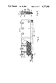
- FIG. 5 is a side view of the drive for the longitudinal or tube sealing jaw
- FIG. 6 is a sectional view through a draw down roller with a slip coupling
- FIG. 7 is a plan view of the drive of the cross-sealing jaws for moving the jaws in opposite direction;
- FIG. 8 is a fragmentary, part-sectional view through the drive of the cross-sealing jaw
- FIG. 9 is a schematic drawing of the operation system of the machine, illustrating electrical connection
- FIG. 10 is a block diagram of the control system of the machine.
- FIG. 11 illustration of the cross-sealing or cross-welding jaws in open position
- FIG. 12 is an illustration of the cross-sealing or cross-welding jaws in position just prior to sealing
- FIG. 13 is an illustration similar to FIG. 12 during sealing
- FIG. 14 is a plan view of a stripper plate
- FIG. 15 is a sectional view of the stripper plate shown in FIG. 14;
- FIG. 16 is a plan view of the film at the position where it passes a sensor and illustrating register marks on the film;
- FIG. 17 is a horizontal sectional view through the longitudinal seal-welding apparatus shown in FIG. 5;
- FIG. 18 is a schematic view illustrating the coupling linkage drive
- FIG. 19 is a fragmentary horizontal view through the longitudinal sealing jaw, and illustrating the position of the overlapping end portions of the film as a longitudinal overlap-seal is being formed.
- FIG. 20 is a fragmentary horizontal view through the longitudinal sealing jaw, and illustrating the position of the overlapping end portions of the film for forming a finseal.
- the form-fill-seal packaging apparatus--see FIGS. 1 and 2-- is used, primarily, to fill a tubular bag formed from a flat, flexible film 2.
- the flat film 2 is, typically, a flat, flexible plastic foil web or film, for example heatsealable polypropylene, weldable polyethylene or the like.
- the film 2 is drawn off a supply reel 3.
- the supply reel 3 is located on a machine frame 4, on suitable bearings, to be supplied as needed.
- a dancer compensating roller arm 5, known as such, is pivotably suppored on the frame to form a variable film supply loop.
- the supply reel 3 is cooperating with a proportional acting brake. Idler roller 5 may be under forced tension and/or form the supply loop by its own weight.
- the film 2 is then guided over a plurality of deflection rollers 6 to a pair of drive rollers 7.
- the drive rollers 7 are driven by suitable sprocket chains or other similar drives from a motor 10 which, preferably, is a servo motor or a stepping motor so that its speed can be accurately controlled.
- the drive roller pair 7 thus draws the film web 2 from the film reel 3 and supplies the film web 2 to the apparatus downstream of the drive roller pair 7.
- the film web 2 is guided over a former 12, of known and standard construction, to be formed into a longitudinally, vertically directed tube 20 surrounding a filling tube 13 on the outside thereof.
- the filling tube 13 is cylindrical and of circual cross section.
- the upper end of filling tube 13 is in communication with a fill funnel 14.
- Products introduced into the funnel 14 in the direction of the arrow B (FIG. 1) can be filled within packages to be formed; a predetermined quantity, by weight, volume, number or the like, in accordance with well known proportioning apparatus, will provide the charge of the products to be filled into the respective packages. Frequently, the charge to be filled into the packages may be determined by weight. Filling arrangements other than the fill funnel 14 as shown may be used.
- the tube 13 is cut longitudinally on the back side thereof up to close to the upper edge of the shoulder of the former 12, so that contact of the fill charges with the continuously moving film will occur early, and the fill charge thus is carried along by the continuously moving film, which may prevent bridging and which draw the product down by the film speed.
- FIGS. 19 and 20 show the vertical edge region 20a,20b, 20c, of the tube 20 which is formed by the former, and that these edge regions 20a, 20b, 20c overlap or are forming a finseal.
- the longitudinal connection apparatus which can be a welding or sealing apparatus, is movable vertically as a unit. The sealing operation is carried out continuously during continuous feed of the web 2 and the then formed tube 20.
- the longitudinal sealing jaw or other sealing or welding apparatus 15 carries out a movement which is shown by curve 18, in chain-dotted lines in FIG. 1.
- the sealing element 15 moves continuously and with the same speed as tube 20 in accordance with the downwardly directed movement, see arrow R of FIG. 1.
- the jaw 15 is lifted off the tube 20, and returned upwardly while keeping some radial distance from the tube 20.
- the upward movement is about three times faster than the downward movement of the tube 20. Since the jaw 15 has a definite length dimension in longitudinal direction, a continuous seal can be formed. The length of the jaw 15 and the vertical movement is shorter than the vertical seal of a package 54 (FIG. 1), thus providing for compact size of the machine.
- the vertical seal made by the jaw 15 overlap to form a continuous verticalla seal.
- the overlapping area is preferably about 10 mm. Movement of the jaw 15 is generated by a multiple bar linkage drive.
- FIG. 5 shows an embodiment of a bar linkage drive 70 for the jaw 15.
- a connecting bar 71 supports two parallel rods 68--see also FIG. 17--which, in turn, carries the sealing jaw 15.
- the parallel rod 68, connecting bar 71 and the jaw 15, as well as a cross bar 45 supporting the jaw 15, carry out an approximately elliptical movement--see curve 18, FIG. 1--in which the vertial downward movement is practically linear and the speed of the seal jaw 15 synchronous to the speed of the film.
- the sealing jaw 15 engages the tube edge portions 20a, 20b, 20c to form the sealed tube 20 during the downward movement.
- the motor 10 is coupled to a pair of shafts 69 (FIG.
- the jaw 15 is secured to the cross element 45 which, in turn, is connected with its ends to the two rods 68.
- the jaw 15 and the seal to be formed on the tube 20 should be accessible and, to provide ready adjustment, the cross bar or carrier 45 is constructed to be movable, so that it can be swung out of the full-line position into the broken-line position shown at 45'.
- the end of the rod 68 remote from the cross brace 45 is supported in a support carrier 71 which, in turn, is connected with two parallel coupling drives 70 (FIGS. 5 and 18).
- a spring for example in form of a compression spring 114, is located between the rear end of the rod 68 and the carrier 71, providing engagement pressure to the sealing jaw 15 on the feeding tube 13, with the tube edge portions 20a, 20b, 20c interposed.
- the pressure can be adjusted by turning nuts 115 on threaded end portions of the rods 68.
- the rods 68 are subdivided into a forward and rearward portion 68a, 68b, respectively, coupled by coupling elements 117.
- the rod portion 68a is secured to or terminates in ends 119 which, at least at their remote terminal, are threaded.
- the two coupling drives 70 control and cause movement of the jaw 15 when the crank 118 (FIG. 18) is driven; when the lower region of the downward movement is reached, the welding jaw will lift off the tube 20 and, after an upward movement, will return to the starting or initial position, thereby carrying out the movement shown in chain-dotted representation in FIGS. 1 and 18.
- the crank 118 is rotatable in the direction of the arrow C (FIG. 18) upon rotation of the shaft stub 120 which forms the end of the shaft 69 (FIG. 5).
- a double-armed swing lever 122 is pivotably linked to the crank 118 at a pivot point 121.
- the lever 122 has an intermediate link pivot point 126.
- the pivot point 126 is pivotably connected to a link 124, the second end of which is connected to a fixed point on the frame 4 of the machine, as shown by the pivot 124a.
- the dimensions and angles of the drive 70 are so arranged that the pivot point 128 carries out an effectively or substantially constant straight-line movement over the region D (FIG. 18).
- To arrive a controlled motion on pivot point 128 in accordance with the drawing the levers are in a defined relation in length and angles to each other. The relationships of the lengths of the lever arms are as follows:
- crank 118 Assuming the crank 118 to have a length of unity or one, the following relationships pertain:
- the cross element 45 can be adjusted on the rod portion 68b by hand-operated clams 45a so that fill tubes of different diameter can be accepted and, further, access to the seaming area of the tume 20 is readily possible.
- Two draw down rollers 25 are located diametrically opposite each other with respect to the fill tube 13 to provide for gentle draw down of the tube 20 over the former 12 and along the tube 13. The draw down rollers 25 are driven at a speed which is higher than that of the drive roller pair 7 provided from motor 10.
- a slip coupling 22 (FIG. 6) is interposed between the drive to the rollers 25 and the drive mechanism for the draw down rollers 25.
- a stationary shaft 24 supports a pully 28 via a ball bearing 26.
- the pully 28 is surrounded by a stationary tube cover 29.
- a disk 30, made of hardened metal, is located at the inner facing surface of the pully 28.
- Disk 30 is secured by screws 31 to the pully 28 to rotate therewith, and is axially pressed outwardly away from the pully 28 by springs 32.
- a friction disk or friction ring 36 is located on a ring structure 34 which is rotatably secured to rotate about the fixed shaft 24 by ball bearings 33.
- the jacket 39 of the roller is made of a material with a high coefficient of friction.
- Each one of the draw down roller sleeves are made of high wear resistant material--see FIGS. 3, 4--are engaged against the tube 20, wrapped about the tube 13.
- the rollers 25 have the tendency to rotate with higher circumferential speed than the feed of the tubes and, consequently, slip will occur between the hardened disk 30 and the friction disk of ring 36 inside of the rollers.
- loosening screw 38 which controls the friction between the outwardly pressed hardened disk 13 and the friction ring 36.
- a plurality of screws 31 and springs 32 are located circumferentially about the fixed shaft 28 to provide for balanced placement of the disk 30, as well known.
- Each one of the shafts 24 is secured to an arm 40' (FIGS. 3, 4) rotatable or pivotable about a horizontal axis. It is pressed by air piston action, not shown, radially inwardly to engage the roller 25 against the tube 20.
- the rollers 25 can be pivoted away from engagement with the fill tube 13, as shown in chain-dotted representation in FIG. 4.
- Drive of the rollers 25 is obtained from the same motor 10 which also drives the drive roller pair 7. Transmission of rotation to the drive rollers 25 is obtained, for example, via a gear 44, to angle drives 46 and drive shafts which are coupled by an internal drive, within the arms 40', to the pully 28.
- a cross-sealing apparatus is located beneath the longitudinal sealing apparatus and beneath the range of movement of the jaw 15.
- the cross-sealing apparatus is formed of two jaws 40, 43 (FIGS. 7, 8) which, simultaneously, form a bottom seal for a new bag, as well as a top seal for an already filled upper bag 54 (FIG. 1).
- the upper top seal 17 (FIG. 1) thus is formed simultaneously with the closing seal 21 for the previously filled and still open tube, so that the initially completely open tube is sealed twice by two parallel spaced seals.
- a severing knife 72 is provided to separate the material of the tube 20 between the two seals, to thereby separate the filled bag from the tube which has been supplied with a bottom seal.
- the welding jaws 40, 43 and all cooperating elements, such as the knife 72 move continuously during the sealing process, and with the same feeding speed as the tube feed speed.
- a vertical system 56 (FIG. 1) is provided, supporting the jaws 40, 43, and moving the jaws up and down in accordance with the double arrow F (FIG. 1).
- Drive motor 58 is coupled to a rack 59 which is driven by a pinion of the motor shaft 58, engaged with a vertical guide 60.
- the rack can be formed as a spindle 59a (FIG. 9) on which a spindle nut 61a is located.
- the system 56 is moved vertically upwardly or downwardly.
- the system 56 includes a motor 62 (FIGS. 1,8, 9) which drives a cam disk 76 over a suitable reduction gearing 62a; (see FIG. 8).
- the cam disk 76 is engaged by a cam follower 82 which controls the opening and closing movement of the jaw 43. Jaw 40 is moved in opposite direction by counteroperating members.
- the cam follower 82 engages the cam disk 76 which is coupled to the shaft 78.
- the cam follower 82 is coupled to the rod 80, at the end of which the welding jaw 43 is located.
- jaw 43 Upon rotation of the cam disk 76, jaw 43 will move in the direction of the double arrow K of FIG. 8.
- the various steps in the movement are shown in FIGS. 11 to 13.
- the synchronously but oppositely directed movement of the jaw 40 is controlled from the same cam disk 76 (see FIG. 7) by a member 102, fixed with the rod 80 by a bolt 105.
- arms 100 are connected by link connections 104.
- Levers 99 are coupled with the end of the arms 100.
- the levers 99 are pivotable about a fulcrum 108.
- the outer end of each lever 99 is connected by a further link 104 with a first rod 101.
- Second rods 97 are coupled by links 110 with the first rods and guided in guide sleeve 98. Both second rods 97 are supporting a cross bar 77, connected with the jaw 40 and a casing 75 for the cutting apparatus.
- a spring 79 pushes against the member 102.
- a cutter 72 is located centrally within the jaw 40--see FIGS. 7 and 8--which is guided in a casing 77 and operated by a cylindrical end portion 74, subjected to hydraulic or pneumatic fluid pressure, when the filled and closed bag 54 should be severed from the tube.
- the two jaws 40, 43 have upper and lower portions--see FIGS. 1 and 8--which are heated electrically to sealing or welding temperatures, respectively, and to form, simultaneously, with the upper portion of the jaw 43 a bottom seal of the tube 20 and, with the lower portion of the jaw 43, a top seal for the already filled bag 54.
- the tube portions of the jaws 40, 43 are spaced from each other, so that the closing to seal 17 (FIG. 1) of the already filled bag 54 is generated simultaneously with the bottom seal 21.
- Sealing and severing structures are known, and may be in accordance with any suitable construction.
- a perferred structure, which also provides for control of the sealing pressure, is described in U.S. Ser. No. 96/830,641, filed Feb. 18, 1986, KLINKEL (claiming priority Swiss Application 738/85).
- the tube 20 is fed continuously.
- the entire system 56 is fed at the same tube feed speed in the direction of the arrow R (FIG. 5) downwardly, as the long seal is being made.
- the sealing jaws 40, 43 are closed at the upper end position of the system 56--see FIG. 1--and thus, during the sealing process, the closed sealing jaws 40, 43 move with the feed speed of the tube 20 downwardly.
- the goods to be packaged are filled through the fill funnel 14 into the interior of the fill tube 13, and, in measured quantity, are supplied to the tube 20 as it moves downwardly and along the fill tube 13.
- severing knife 72 (FIG.
- the pulse to operate the severing knife 72 can be provided after the sealing jaws 40, 43 have closed, with some time delay, that is, based on timing of the operation of the sealing jaws the seal itself, or as a function of the position of the system 56 along the height of the apparatus. Admission of pressure fluid to operate the knife 72 can be controlled electrically or by a cam or the like, as desired.
- jaws 40, 43 open based on suitable rotation of the cam disk 76, or a crank of other control apparatus.
- the direction of rotation of the drive motor then is reversed and its upward speed is increased, so that the system 56 is again moved to the starting position.
- hydraulic or pneumatic cylinder-piston units can be used controlled, for example, by electromagnetic valves.
- a shaker arm 51 which osciallates horizontally, as shown by the double arrow H (FIG. 1).
- a precompression of the bag may be desirable if the fill goods 95 (FIG. 11), by example chips, have a tendency to block within the bag, and thus prevent complete filling of the bag. If such fill goods are to be filled in bags, stripper elements are preferably provided to permit compression of the bags in longitudinal direction.
- Two stripper elements are located below the sealing or welding jaws 40, 43 mechanically coupled to the jaws 40, 43.
- the stripper jaws, blades or plates 87 are spring-loaded by springs 89, positioned with the housing 85 for the jaws or plates 87.
- the stripper jaws or plates 87 thus, travel both horizontally as well as vertically together with the sealing jaws 40, 43.
- FIGS. 14 and 15 show such stripper means with more details.
- the stripper blade or plate 87 is movably arranged in the housing 85, comprising two cover plates 123 and 124 and an intermediate member 131 secured by bolts 126. Between the rear side of the stripper plate 87 and the intermediate member 131 a plurality of springs 89 are arranged.
- a bore 134 extends in longitudinal direction at the forward end of the stripper plate 87, having a plurality of upwardly directed small openings 136.
- the bore 134 is connected with a tube 140 for conducting compressed air.
- the movement of the spring loaded stripper plate 87 is limited by a step 128.
- the air jets are provided for cooling the bottom seal of the tube just after opening of the jaws 40, 43.
- Holding elements for fixing the stripping members to the jaws 40, 43 are well known in structure design, have been omitted for clarity from the drawing.
- the sealing jaws 40, 43 are moved towards each other--see FIG. 12--upon operation of the cam disk 76, a crank arm, or the like, as described in detail above in connection with FIGS. 7 and 8.
- the two sealing jaws 40, 43 will be spaced from each other in advance of engagement of the stripper plates 87 against the respective walls of the tube 20, then forming the bag 54. Initially, thus, no sealing proces will start.
- the stripper plates 87 will engage and pinch, not completely closed for discharging air, against the tube 20, causing the springs 89 to be compressed. In the position in which the stripper plates 87 have engaged the tube, downward movement of the jaws 40 will occur, together with the stripper plates 87.
- the downward movement if this embodiment is used, is controlled to be considerably faster than the continuous feed movement of the tube 20. This compresses the articles of goods 95 within the tube 54 downwardly. Under control of the cam 76, or equivalent control, the sealing jaws will then close completely and the previously described sealing process to form the sealing 17 of the bag 54 is carried out, as best seen in FIG. 13. During this operation, the two stripper plates 87 are almost engaged against the tube 20. The severing knife 72 is then operated by the piston 74. The bag, closed at the top and bottom, is severed. As described, the sealing process is carried out during the continuous movement of the tube, the sealing jaws 49, 43 then operating at the same speed as the feeding speed of the tube 20, in downward direction. Since, simultaneously with the top seal of a lower bag, the bottom seal of the next upper bag is formed, fill of the upper bag by fill goods 95 can be started as soon as the seal jaws have completely closed.
- the seal jaws 40, 53, and with them the stripper plates 87 are opened after the knife 74 has severed the bag 54 from the upper, still open bag portion, and the entire system 56, together with the jaws 40, 43 and the stripper plates 87, is raised upwardly and with increased speed, so that it will be available to start the next stripping, sealing and severing cycle, that is, in the starting position shown in FIG. 11.
- Differential speed in vertical direction, arrow F (FIG. 1) of the entire system 56, including the jaws 40, 43 and the stripper plates 87, can be easily controlled by controlling the speed of the motor 58 by suitable programmed control of an electrical movement of the jaws 40, 43 and with them of the stripper plates 87. Opening and timing is controlled by control of the associated motor 62, or by a suitable cam track on the cam disk 76.
- Synchronized operation of the various elements of the overall feeding system is controlled by an electrical control system, shown in detail in FIGS. 9 and 10.
- the drive roller pair 7 continously removes the film 2 from the film reel 3.
- the motor 10 which is a servo motor or a stepping motor, is speed-controlled by a control unit 84, which controls motor controllers or control unit 88 associated with the individual motors.
- a motor power supply or power source 87 provides the necessary operating power.
- the motor controller may be a driver circuit.
- a sensor 19 which, preferably, is a photo cell, for example a photo transistor or other photosensitive element, is located between the pair of drive rollers 7 and the former 12. The sensor 19 responds to differences in brightness or whether an element is transparent or opaque and, thus, responds to the marks 53 shown in FIG. 16. Rather than providing marks on a film web, perforations or other indicia of position of a specific transverse portion of the film can be used.
- the space between two markers 53 correspond to a predetermined space associated with each other of the bags 54; of course, a plurality of markers may correspond to any such length, and the number of markers which are to be used on any one bag can be varied, as desired.
- the length increments between two markers 53 correspond to a predetermined number of pulses, signals or rotary incremental steps or angular rotation carried out by motor 10. If motor 10 is a servo motor operating in analog mode, the length increments will control the rotary angle through which the servo motor will turn; if the motor 10 is a stepping motor, the length between two markers 53 will determine the number of steps, and hence the entire angular rotation of the motor.
- the step or pulse number which the motor should carry out to feed the film to provide the packages of predetermined length is calculated and/or computed by a computer (CPU) 90 (FIG. 9) with the number of pulses which occur in the period of time between scanning of two adjacent markers 53 by the photo cell 19.
- the motor controller 86 Upon deviation of the scanned or actual pulse number from a command or preset value, the motor controller 86 is controlled to either suppress pulses so that the motor will run slower, or increase the number of pulses to increase the motor speed.
- the corrected values are supplied to motors 58 and 62 as well as to servo motor 10, so that the motor will operate in synchronism.
- synchronism as used herein is to be understood that the motors operate in synchronous relationship with respect to each other; the individual speed in revolutions of angular deflection of each motor, per unit time, need not be the same; rather “synchronous relationship” means that if the speed of the motor 10 changes, the speed or angular rotation per unit time of the motors 58 and 62 changes in proportion.
- the longitudinal seal generated by the longitudinal sealing jaw 15 is shorter than the length of the packages.
- the stroke per unit time or the rhythm or cadence of operation of the longitudinal jaw 15 must be substantially faster than the stroke time or cadence of operation of the transverse sealing jaw 40, 43 or, respectively, of the entire system 56.
- the control system provides for synchronized, conjoint operation in vertical direction of the jaw 15, in cadence with feed of the film and hence of the tube 20, as well as for opening and closing movement of the jaws 40, 43 during the sealing and welding which, in turn, is in synchronism and cadence with the separating distance defining the length of the packages and, also with the spacing between sequential markers 53.
- Inaccuracies in feed of the film for example due to slippage of the film, tolerances in film thickness and the like, thus cannot become additive, and are immediately corrected within the inertia of the system, which is small.
- the motors 58, 62 each, have a motor controller 86 and a pulse generator 88 connected thereto, the pulse generators 88 providing the operating pulses for the motors 58, 62 which, preferably, are servo motors--see FIG. 10.
- the sealing jaws 15, 40, 43 shown only schematically in FIG. 10, are each supplied from a sealing jaw power supply unit 94 and their relative temperature are scanned and supplied to an analog/digital convertor 96. The output is fed back digitally to the CPU 90 to form a close lapp.
- control unit 84 and CPU 90 preferably, are a microcomputer suitable programmed to carry out the respective operating functions.
- a command panel and display unit 65 provides for data input into the input or control unit 84, and display of, respectively, the data being into the input or control unit 84 and, thereafter, continued display of operating characteristics of the unit, to provide for monitoring of the respective elements.
- the unit 84 is an opto-isolated digital input unit, with analog/digital conversion capability, if needed, and receives, among other inputs, the input from sensor 19.
- Clock pulses are provided by the CPU 90 which can be in form of a supervisory control unit of the type INTEL 8086, with its own clock source.
- Power supply 92 is conventional, for the control unit type 8086.
- the connection between the control unit type 8086 and all the other electrical and electronic components can be by means of an SMP bus.
- the motor controllers 86 can take the form of control units INTEL 8049 or 8085, respectively, depending on power requirements.
- the control panel and display can be keyboard and display unit 8085, and matched to the respective motor controls.
- control unit 84, 90 By suitably programming control unit 84, 90, the speed of the jaw closing of the sealing jaws 40, 43 and the timing thereof can be controlled in time relation to the vertical movement of the system 56, as described in connection with FIGS. 11-13.
- the unit 84 and CPU 90 controlled by the command panel 65 can be programmed as well known in connection with timing sequences and comparison technology.
- welding seals can be made on the packages, both in longitudinal as well as in transverse direction, depending on the material of the film to be used.
- the jaws 15, 40, 43 thus, can be adapted, as desired, to the material and may be either sealing jaws for heat sealable material or welding jaws for thermoplastic materials.
- connection between the respective pulse generators 88 and the motors 10, 58, 62 is illustrated merely in the form of five lines, although, of course, more or fewer numbers of lines can be used.
- the motors 58 and 62 are reversible; motor 10, which drives the feed of the film by driving the drive roller pair 7 and the draw-down mechanism 25 and longitudinal seal bar need operate only in one direction.
- the motors 58, 62 are reversible-type motors to provide, respectively, for reciprocating vertical movement of the jaw pair 40, 43 and for opening and closing, respectively, of the jaws 40, 43.
- the control units can, additionally, control other parameters used in making the bags, for example the pressure of the jaws 40, 43 with respect to each other, as explained in greater detail in the referenced application Ser. No. 06/830,641, filed Feb. 18, 1986, KLINKEL, now U.S. Pat. No. 4,713,047.
Abstract
Description
Claims (22)
Applications Claiming Priority (4)
| Application Number | Priority Date | Filing Date | Title |
|---|---|---|---|
| CH304/86 | 1986-01-27 | ||
| CH304/86A CH669766A5 (en) | 1986-01-27 | 1986-01-27 | |
| CH3079/86A CH671198A5 (en) | 1986-07-31 | 1986-07-31 | |
| CH3079/86 | 1986-07-31 |
Publications (1)
| Publication Number | Publication Date |
|---|---|
| US4757668A true US4757668A (en) | 1988-07-19 |
Family
ID=25684168
Family Applications (1)
| Application Number | Title | Priority Date | Filing Date |
|---|---|---|---|
| US07/006,623 Expired - Fee Related US4757668A (en) | 1986-01-27 | 1987-01-22 | Method and apparatus for form-fill-seal packaging of articles |
Country Status (2)
| Country | Link |
|---|---|
| US (1) | US4757668A (en) |
| CA (1) | CA1277583C (en) |
Cited By (69)
| Publication number | Priority date | Publication date | Assignee | Title |
|---|---|---|---|---|
| US4885900A (en) * | 1987-05-12 | 1989-12-12 | Rovema Verpackungsmaschinen Gmbh | Driving method and system for controlling a tubular-bag machine |
| US4947618A (en) * | 1987-09-23 | 1990-08-14 | Rovema Verpackungsmaschinen Gmbh | Bag sealing device |
| US4996825A (en) * | 1989-01-31 | 1991-03-05 | Kliklok Corporation | Combined blousing, stripping and sealing for bag forming and method |
| US5031386A (en) * | 1988-11-07 | 1991-07-16 | Rovema Verpackungsmachinen Gmbh | Tubular bagging machine |
| US5038550A (en) * | 1989-02-02 | 1991-08-13 | Du Pont Canada, Inc. | Vertical form and fill machine improvements |
| US5062253A (en) * | 1989-01-31 | 1991-11-05 | Kliklok Corporation | Combined film feeding stripping and sealing for bag forming and method |
| US5117612A (en) * | 1988-10-18 | 1992-06-02 | Rovema Verpackungsmaschinen Gmbh | Method and apparatus for controlling the movement of cross-welding jaws of a tubular bagging machine |
| US5177935A (en) * | 1990-03-06 | 1993-01-12 | Pilkington Insulation Limited | Packing machine |
| US5400565A (en) * | 1992-06-29 | 1995-03-28 | Pacmac, Inc. | Vertical form, fill and seal packaging machine for making recloseable product filled bags |
| US5412927A (en) * | 1993-11-03 | 1995-05-09 | Kawashimaseisakusyo Co., Ltd. | Longitudinal bag-making, filling and packaging machine |
| US5505037A (en) * | 1992-06-29 | 1996-04-09 | Pacmac, Inc. | Vertical form, fill and seal machine for making recloseable bags |
| US5533322A (en) * | 1994-03-11 | 1996-07-09 | Kliklok Corporation | Continuous vertical form-fill-seal packaging machine with constant motion carriage |
| US5540035A (en) * | 1994-12-07 | 1996-07-30 | Kliklok Corporation | Continuous vertical form-fill-seal packaging machine with synchronized product clamp |
| US5622033A (en) * | 1994-12-23 | 1997-04-22 | Ishida Co., Ltd. | Transverse sealer for a bag maker |
| WO1997028045A1 (en) * | 1996-01-30 | 1997-08-07 | Tetra Laval Holdings & Finance S.A. | Sealing apparatus |
| US5678392A (en) * | 1993-07-09 | 1997-10-21 | Tetra Laval Holdings & Finance S.A. | Residual product removing apparatus |
| US5768852A (en) * | 1992-06-29 | 1998-06-23 | Pacmac, Inc. | Vertical form, fill and seal machine, components and method for making reclosable bags |
| US5881539A (en) * | 1996-06-04 | 1999-03-16 | Ishida Co., Ltd. | Transverse sealer for a packaging machine |
| US5930983A (en) * | 1992-06-29 | 1999-08-03 | Pacmac, Inc. | Form, fill and seal packaging machine with bag squeezer and method |
| US5937614A (en) * | 1994-02-01 | 1999-08-17 | Watkins; David Leonard | Bag sealing apparatus |
| US5974770A (en) * | 1996-11-26 | 1999-11-02 | Shikoku Kakoki Co., Ltd. | Press in a filling and packaging apparatus |
| US6006503A (en) * | 1995-04-01 | 1999-12-28 | Molins, Plc. | Packaging machine with a stripping device |
| US6029428A (en) * | 1992-06-29 | 2000-02-29 | Pacmac, Inc. | Convertible form, fill and seal packaging machine |
| US6044624A (en) * | 1997-04-07 | 2000-04-04 | Focke & Co. (Gmbh & Co.) | Process and apparatus for producing (filling) bag packs for tobacco |
| US6052971A (en) * | 1998-11-09 | 2000-04-25 | Hayssen, Inc. | Offset stripper and stripping method for vertical form, fill and seal machine |
| US6167681B1 (en) | 1996-01-30 | 2001-01-02 | Tetra Laval Holdings & Finance S.A. | Sealing apparatus |
| WO2001042091A2 (en) * | 1999-12-07 | 2001-06-14 | Aisa Automation Industrielle Sa | Twin-chambered container |
| US6519922B1 (en) * | 1999-07-07 | 2003-02-18 | Cmd Corporation | Device for the production of tubular bags |
| US6539692B1 (en) * | 1998-12-18 | 2003-04-01 | Siptop Packaging, Inc. | Form, fill and seal container forming apparatus |
| US6544382B2 (en) | 1999-11-15 | 2003-04-08 | Pactiv Corporation | Apparatus for high-speed heating and cooling of a polymer |
| US6553744B1 (en) | 1992-06-29 | 2003-04-29 | Pacmac, Inc. | Packaging machine |
| US20030229943A1 (en) * | 2002-06-17 | 2003-12-18 | Paramount Bedding, Inc., Dba Paramount Manufacturing | Coil spring containing mattress and method |
| US6739107B1 (en) | 2001-02-28 | 2004-05-25 | Paramount Bedding, Inc. | Method and apparatus for compressing a mattress with an inner coil spring |
| US6876896B1 (en) | 1999-04-26 | 2005-04-05 | Ab Tetrapak | Variable motion system and method |
| WO2005030588A1 (en) * | 2003-09-24 | 2005-04-07 | Manfred Hauers | Continuously operating vertical bag forming, filling and sealing machine |
| US20050193689A1 (en) * | 2004-03-05 | 2005-09-08 | Glopak Inc. | Convertible computer controlled FFS bagging machine |
| US20050241269A1 (en) * | 2000-11-01 | 2005-11-03 | Cfs Weert B.V. | Form-fill-seal machine |
| US20060075724A1 (en) * | 2004-10-09 | 2006-04-13 | Roman Kammler | Method and apparatus for positioning a welding jaw |
| ES2253980A1 (en) * | 2004-04-29 | 2006-06-01 | Coalza, S.L. | Control system for operating clamps of cylindrical hay baler, has local console panel to transmit working sequence to automatic programmable robot, which in turn makes actuator drive opening/closing action of clamps |
| US20080066430A1 (en) * | 2006-09-15 | 2008-03-20 | Triangle Package Machinery Company | Continuous motion drive mechanism for a form, fill, and seal machine |
| US20080072537A1 (en) * | 2005-04-11 | 2008-03-27 | Ishida Co., Ltd | Packaging machine |
| CN100408435C (en) * | 2001-11-19 | 2008-08-06 | 戚小进 | Packing speed controlling method and apparatus for longitudinal and transverse packing rollers of packing machine |
| US20090113852A1 (en) * | 2007-05-31 | 2009-05-07 | Philip Morris Usa Inc. | Product in seal deflection device |
| US20090127323A1 (en) * | 2007-11-15 | 2009-05-21 | Bernhard Zeiler | Packaging machine and packages made therewith |
| US20100199614A1 (en) * | 2007-08-23 | 2010-08-12 | Tna Australia Pty Limited | Packaging machine for block bottom bags |
| US20110177435A1 (en) * | 2010-01-20 | 2011-07-21 | International Business Machines Corporation | Photomasks having sub-lithographic features to prevent undesired wafer patterning |
| US20110192117A1 (en) * | 2010-02-10 | 2011-08-11 | Lubezny Vadim A | Seal and cut method and apparatus |
| US20110304085A1 (en) * | 2010-06-09 | 2011-12-15 | Karl Scott Fleischer | Self-aligning pivotable mandrel assembly |
| US20120213461A1 (en) * | 2010-06-09 | 2012-08-23 | Karl Scott Fleischer | Self-aligning pivotable mandrel assembly |
| ES2401254A2 (en) * | 2011-04-18 | 2013-04-18 | Tna Australia Pty Limited | Barcode scanner |
| WO2013149718A1 (en) * | 2012-04-03 | 2013-10-10 | Mondo Servizi S.R.L. | Frame for a packaging machine |
| EP2664554A1 (en) * | 2012-05-14 | 2013-11-20 | Ulma Packaging Technological Center, S. Coop | Machine and method for vertical packaging |
| US20140090337A1 (en) * | 2011-05-11 | 2014-04-03 | P.F.M. Spa | Vertical packaging machine for food products |
| EP2921282A1 (en) * | 2014-03-19 | 2015-09-23 | GEA Food Solutions Weert B.V. | Vertical flow wrapper with an epicyclic gear |
| WO2015200911A1 (en) * | 2014-06-27 | 2015-12-30 | Pregis Innovative Packaging Llc | Self-contained computational device for protective packaging systems |
| US20160023789A1 (en) * | 2013-10-23 | 2016-01-28 | Guangzhou Yilugao Packing Machinery Technic Co., Ltd | Bag forming device and packaging machine comprising the same |
| US20160297554A1 (en) * | 2013-12-03 | 2016-10-13 | Ishida Co., Ltd | Form-fill-seal machine and bag-making packaging machine |
| DE102015223721A1 (en) * | 2015-11-30 | 2017-06-01 | Robert Bosch Gmbh | Apparatus for forming at least one web of 3-edge sealed bags |
| US9963253B2 (en) | 2011-07-11 | 2018-05-08 | Altria Client Services Llc | Air accelerator dosing tube |
| WO2018189256A1 (en) * | 2017-04-13 | 2018-10-18 | Gea Food Solutions Weert B.V. | Vertical flow wrapper with a crank mechanism |
| WO2019060206A1 (en) * | 2017-09-20 | 2019-03-28 | Triangle Package Machinery Co. | Vertical form, fill and seal machine with ultrasonic vertical seal and reclosable fastener attachment |
| US20190127092A1 (en) * | 2017-11-01 | 2019-05-02 | Ishida Co., Ltd. | Bag-making and packaging apparatus |
| US10351283B2 (en) * | 2015-12-17 | 2019-07-16 | Khs Usa, Inc. | Magnetically operated sealing bar assembly for packaging machines |
| US10358244B2 (en) | 2015-10-26 | 2019-07-23 | Triangle Package Machinery Co. | Rotatable sealing jaw assembly for a form, fill and seal machine |
| WO2020078879A1 (en) * | 2018-10-19 | 2020-04-23 | Gea Food Solutions Weert B.V. | Vertical flow wrapper and method to produce packages with a reduced gas content |
| US11207848B2 (en) * | 2016-07-01 | 2021-12-28 | Hangzhou Bing Jia Technology Co., Ltd | Buffering gas cushion machine |
| US11230064B2 (en) * | 2017-02-28 | 2022-01-25 | Gea Food Solutions Weert B.V. | Inspection of a vertical flow-wrapper |
| US20220192443A1 (en) * | 2019-05-17 | 2022-06-23 | Closac Ag | Waterless toilet |
| WO2023244909A1 (en) | 2022-06-17 | 2023-12-21 | Dow Global Technologies Llc | Multilayer heat-seal film |
Citations (10)
| Publication number | Priority date | Publication date | Assignee | Title |
|---|---|---|---|---|
| US2915866A (en) * | 1958-05-12 | 1959-12-08 | Lynch Corp | Product settling means for draw type wrapping machine |
| US3779836A (en) * | 1971-03-26 | 1973-12-18 | Woodman Co | Tube seamer with clamp action |
| US4128985A (en) * | 1977-10-31 | 1978-12-12 | Package Machinery Company | Control system for package making machine |
| US4288965A (en) * | 1979-08-27 | 1981-09-15 | Hayssen Manufacturing Company | Form-fill-seal packaging method and apparatus |
| US4295922A (en) * | 1979-09-17 | 1981-10-20 | Developak Corporation | Tube side seam heat sealer |
| US4391081A (en) * | 1980-09-08 | 1983-07-05 | Hayssen Manufacturing Company | Method of and apparatus for forming, filling and sealing packages |
| US4525977A (en) * | 1983-05-13 | 1985-07-02 | Doboy Packaging Machinery, Inc. | Wrapping machine and method |
| US4532753A (en) * | 1983-02-18 | 1985-08-06 | Hayssen Manufacturing Company | Method of and apparatus for forming, filling and sealing packages |
| US4549386A (en) * | 1983-04-18 | 1985-10-29 | Baker Perkins Holdings Plc | Form-fill-seal wrapping apparatus |
| US4563862A (en) * | 1984-10-23 | 1986-01-14 | Kliklok Corporation | Package forming apparatus with combined holding and stripper mechanism |
-
1987
- 1987-01-22 US US07/006,623 patent/US4757668A/en not_active Expired - Fee Related
- 1987-01-26 CA CA000528164A patent/CA1277583C/en not_active Expired - Lifetime
Patent Citations (11)
| Publication number | Priority date | Publication date | Assignee | Title |
|---|---|---|---|---|
| US2915866A (en) * | 1958-05-12 | 1959-12-08 | Lynch Corp | Product settling means for draw type wrapping machine |
| US3779836A (en) * | 1971-03-26 | 1973-12-18 | Woodman Co | Tube seamer with clamp action |
| US4128985A (en) * | 1977-10-31 | 1978-12-12 | Package Machinery Company | Control system for package making machine |
| US4288965A (en) * | 1979-08-27 | 1981-09-15 | Hayssen Manufacturing Company | Form-fill-seal packaging method and apparatus |
| US4288965B1 (en) * | 1979-08-27 | 1985-03-26 | ||
| US4295922A (en) * | 1979-09-17 | 1981-10-20 | Developak Corporation | Tube side seam heat sealer |
| US4391081A (en) * | 1980-09-08 | 1983-07-05 | Hayssen Manufacturing Company | Method of and apparatus for forming, filling and sealing packages |
| US4532753A (en) * | 1983-02-18 | 1985-08-06 | Hayssen Manufacturing Company | Method of and apparatus for forming, filling and sealing packages |
| US4549386A (en) * | 1983-04-18 | 1985-10-29 | Baker Perkins Holdings Plc | Form-fill-seal wrapping apparatus |
| US4525977A (en) * | 1983-05-13 | 1985-07-02 | Doboy Packaging Machinery, Inc. | Wrapping machine and method |
| US4563862A (en) * | 1984-10-23 | 1986-01-14 | Kliklok Corporation | Package forming apparatus with combined holding and stripper mechanism |
Cited By (105)
| Publication number | Priority date | Publication date | Assignee | Title |
|---|---|---|---|---|
| US4885900A (en) * | 1987-05-12 | 1989-12-12 | Rovema Verpackungsmaschinen Gmbh | Driving method and system for controlling a tubular-bag machine |
| US4947618A (en) * | 1987-09-23 | 1990-08-14 | Rovema Verpackungsmaschinen Gmbh | Bag sealing device |
| US5117612A (en) * | 1988-10-18 | 1992-06-02 | Rovema Verpackungsmaschinen Gmbh | Method and apparatus for controlling the movement of cross-welding jaws of a tubular bagging machine |
| US5031386A (en) * | 1988-11-07 | 1991-07-16 | Rovema Verpackungsmachinen Gmbh | Tubular bagging machine |
| US4996825A (en) * | 1989-01-31 | 1991-03-05 | Kliklok Corporation | Combined blousing, stripping and sealing for bag forming and method |
| US5062253A (en) * | 1989-01-31 | 1991-11-05 | Kliklok Corporation | Combined film feeding stripping and sealing for bag forming and method |
| US5038550A (en) * | 1989-02-02 | 1991-08-13 | Du Pont Canada, Inc. | Vertical form and fill machine improvements |
| US5177935A (en) * | 1990-03-06 | 1993-01-12 | Pilkington Insulation Limited | Packing machine |
| US5505037A (en) * | 1992-06-29 | 1996-04-09 | Pacmac, Inc. | Vertical form, fill and seal machine for making recloseable bags |
| US5768852A (en) * | 1992-06-29 | 1998-06-23 | Pacmac, Inc. | Vertical form, fill and seal machine, components and method for making reclosable bags |
| US6029428A (en) * | 1992-06-29 | 2000-02-29 | Pacmac, Inc. | Convertible form, fill and seal packaging machine |
| US6047521A (en) * | 1992-06-29 | 2000-04-11 | Pacmac, Inc. | Vertical form, fill and seal machine for making reclosable bags |
| US5930983A (en) * | 1992-06-29 | 1999-08-03 | Pacmac, Inc. | Form, fill and seal packaging machine with bag squeezer and method |
| US5400565A (en) * | 1992-06-29 | 1995-03-28 | Pacmac, Inc. | Vertical form, fill and seal packaging machine for making recloseable product filled bags |
| US6553744B1 (en) | 1992-06-29 | 2003-04-29 | Pacmac, Inc. | Packaging machine |
| US5678392A (en) * | 1993-07-09 | 1997-10-21 | Tetra Laval Holdings & Finance S.A. | Residual product removing apparatus |
| US5787690A (en) * | 1993-07-09 | 1998-08-04 | Tetra Laval Holdings & Finance S.A. | Residual product removing apparatus |
| US5412927A (en) * | 1993-11-03 | 1995-05-09 | Kawashimaseisakusyo Co., Ltd. | Longitudinal bag-making, filling and packaging machine |
| US5937614A (en) * | 1994-02-01 | 1999-08-17 | Watkins; David Leonard | Bag sealing apparatus |
| US5533322A (en) * | 1994-03-11 | 1996-07-09 | Kliklok Corporation | Continuous vertical form-fill-seal packaging machine with constant motion carriage |
| US5540035A (en) * | 1994-12-07 | 1996-07-30 | Kliklok Corporation | Continuous vertical form-fill-seal packaging machine with synchronized product clamp |
| US5622033A (en) * | 1994-12-23 | 1997-04-22 | Ishida Co., Ltd. | Transverse sealer for a bag maker |
| US6006503A (en) * | 1995-04-01 | 1999-12-28 | Molins, Plc. | Packaging machine with a stripping device |
| WO1997028045A1 (en) * | 1996-01-30 | 1997-08-07 | Tetra Laval Holdings & Finance S.A. | Sealing apparatus |
| US6167681B1 (en) | 1996-01-30 | 2001-01-02 | Tetra Laval Holdings & Finance S.A. | Sealing apparatus |
| US5881539A (en) * | 1996-06-04 | 1999-03-16 | Ishida Co., Ltd. | Transverse sealer for a packaging machine |
| US5974770A (en) * | 1996-11-26 | 1999-11-02 | Shikoku Kakoki Co., Ltd. | Press in a filling and packaging apparatus |
| US6044624A (en) * | 1997-04-07 | 2000-04-04 | Focke & Co. (Gmbh & Co.) | Process and apparatus for producing (filling) bag packs for tobacco |
| US6052971A (en) * | 1998-11-09 | 2000-04-25 | Hayssen, Inc. | Offset stripper and stripping method for vertical form, fill and seal machine |
| US6539692B1 (en) * | 1998-12-18 | 2003-04-01 | Siptop Packaging, Inc. | Form, fill and seal container forming apparatus |
| US6876896B1 (en) | 1999-04-26 | 2005-04-05 | Ab Tetrapak | Variable motion system and method |
| US20070101684A1 (en) * | 1999-07-07 | 2007-05-10 | Cmd Corporation | Device For The Production Of Tubular Bags |
| US20050155331A1 (en) * | 1999-07-07 | 2005-07-21 | Cmd Corporation | Device for the production of tubular bags |
| US6519922B1 (en) * | 1999-07-07 | 2003-02-18 | Cmd Corporation | Device for the production of tubular bags |
| US7213384B2 (en) | 1999-07-07 | 2007-05-08 | Cmd Corporation | Device for the production of tubular bags |
| US20040045258A1 (en) * | 1999-07-07 | 2004-03-11 | Cmd Corporation | Device for the production of tubular bags |
| US7069709B2 (en) | 1999-07-07 | 2006-07-04 | Cmd Corporation | Device for the production of tubular bags |
| US6544382B2 (en) | 1999-11-15 | 2003-04-08 | Pactiv Corporation | Apparatus for high-speed heating and cooling of a polymer |
| WO2001042091A2 (en) * | 1999-12-07 | 2001-06-14 | Aisa Automation Industrielle Sa | Twin-chambered container |
| AU771401B2 (en) * | 1999-12-07 | 2004-03-18 | Aisa Automation Industrielle S.A. | Twin-chambered container |
| WO2001042091A3 (en) * | 1999-12-07 | 2001-11-01 | Automation Industrielle Sa | Twin-chambered container |
| US20030222099A1 (en) * | 1999-12-07 | 2003-12-04 | Gerhard Keller | Device for producing two-chamber containers |
| US6905323B2 (en) | 1999-12-07 | 2005-06-14 | Aisa Automation Industrielle Sa | Device for producing two-chamber containers |
| US20050241269A1 (en) * | 2000-11-01 | 2005-11-03 | Cfs Weert B.V. | Form-fill-seal machine |
| US7082737B2 (en) * | 2000-11-01 | 2006-08-01 | Cfs Weert B.V. | Form-fill-seal machine |
| US6739107B1 (en) | 2001-02-28 | 2004-05-25 | Paramount Bedding, Inc. | Method and apparatus for compressing a mattress with an inner coil spring |
| CN100408435C (en) * | 2001-11-19 | 2008-08-06 | 戚小进 | Packing speed controlling method and apparatus for longitudinal and transverse packing rollers of packing machine |
| US20030229943A1 (en) * | 2002-06-17 | 2003-12-18 | Paramount Bedding, Inc., Dba Paramount Manufacturing | Coil spring containing mattress and method |
| US6889398B2 (en) | 2002-06-17 | 2005-05-10 | Paramount Bedding, Inc. | Coil spring containing mattress and method |
| US20070163214A1 (en) * | 2003-09-24 | 2007-07-19 | Manfred Hauers | Continuously operating vertical bag forming filling and sealing machine |
| US7448188B2 (en) * | 2003-09-24 | 2008-11-11 | Manfred Hauers | Continuously operating vertical bag forming filling and sealing machine |
| WO2005030588A1 (en) * | 2003-09-24 | 2005-04-07 | Manfred Hauers | Continuously operating vertical bag forming, filling and sealing machine |
| US7076935B2 (en) * | 2004-03-05 | 2006-07-18 | Glopak Inc. | Convertible computer controlled FFS bagging machine |
| US20050193689A1 (en) * | 2004-03-05 | 2005-09-08 | Glopak Inc. | Convertible computer controlled FFS bagging machine |
| ES2253980A1 (en) * | 2004-04-29 | 2006-06-01 | Coalza, S.L. | Control system for operating clamps of cylindrical hay baler, has local console panel to transmit working sequence to automatic programmable robot, which in turn makes actuator drive opening/closing action of clamps |
| US20060075724A1 (en) * | 2004-10-09 | 2006-04-13 | Roman Kammler | Method and apparatus for positioning a welding jaw |
| US20080072537A1 (en) * | 2005-04-11 | 2008-03-27 | Ishida Co., Ltd | Packaging machine |
| US20080066430A1 (en) * | 2006-09-15 | 2008-03-20 | Triangle Package Machinery Company | Continuous motion drive mechanism for a form, fill, and seal machine |
| US20090113852A1 (en) * | 2007-05-31 | 2009-05-07 | Philip Morris Usa Inc. | Product in seal deflection device |
| US8402724B2 (en) * | 2007-05-31 | 2013-03-26 | Philip Morris Usa Inc. | Method and apparatus for product in seal deflection |
| US20100199614A1 (en) * | 2007-08-23 | 2010-08-12 | Tna Australia Pty Limited | Packaging machine for block bottom bags |
| US20110088352A1 (en) * | 2007-11-15 | 2011-04-21 | Bernhard Zeiler | Packaging Machine and Packages Made Therewith |
| US20090127323A1 (en) * | 2007-11-15 | 2009-05-21 | Bernhard Zeiler | Packaging machine and packages made therewith |
| US9028935B2 (en) | 2007-11-15 | 2015-05-12 | Milliken & Company | Packaging machine and packages made therewith |
| US9027314B2 (en) | 2007-11-15 | 2015-05-12 | Milliken & Company | Packaging machine and packages made therewith |
| US20110177435A1 (en) * | 2010-01-20 | 2011-07-21 | International Business Machines Corporation | Photomasks having sub-lithographic features to prevent undesired wafer patterning |
| US20110192117A1 (en) * | 2010-02-10 | 2011-08-11 | Lubezny Vadim A | Seal and cut method and apparatus |
| US8539741B2 (en) | 2010-02-10 | 2013-09-24 | Triangle Package Machinery Company | Seal and cut method and apparatus |
| US20110304085A1 (en) * | 2010-06-09 | 2011-12-15 | Karl Scott Fleischer | Self-aligning pivotable mandrel assembly |
| US20120213461A1 (en) * | 2010-06-09 | 2012-08-23 | Karl Scott Fleischer | Self-aligning pivotable mandrel assembly |
| US8596624B2 (en) * | 2010-06-09 | 2013-12-03 | Stolle Machinery Company, Llc | Self-aligning pivotable mandrel assembly |
| US8596625B2 (en) * | 2010-06-09 | 2013-12-03 | Stolle Machinery Company, Llc | Self-aligning pivotable mandrel assembly |
| ES2401254A2 (en) * | 2011-04-18 | 2013-04-18 | Tna Australia Pty Limited | Barcode scanner |
| ES2401254R1 (en) * | 2011-04-18 | 2013-06-18 | Tna Australia Pty Ltd | BAR CODE SCANNER |
| US9122940B2 (en) | 2011-04-18 | 2015-09-01 | Tna Australia Pty Limited | Barcode scanner |
| US20140090337A1 (en) * | 2011-05-11 | 2014-04-03 | P.F.M. Spa | Vertical packaging machine for food products |
| US9598188B2 (en) * | 2011-05-11 | 2017-03-21 | P.F.M. Spa | Vertical packaging machine for food products |
| US9963253B2 (en) | 2011-07-11 | 2018-05-08 | Altria Client Services Llc | Air accelerator dosing tube |
| US11027860B2 (en) | 2011-07-11 | 2021-06-08 | Altria Client Services Llc | Delivery apparatus |
| US11618596B2 (en) | 2011-07-11 | 2023-04-04 | Altria Client Services Llc | Method of making delivery apparatus |
| EP2834548B1 (en) | 2012-04-03 | 2017-11-01 | Unicrim Srl | Frame for a packaging machine |
| CN104412025A (en) * | 2012-04-03 | 2015-03-11 | 蒙多贸易有限公司 | Frame for a packaging machine |
| US9791092B2 (en) | 2012-04-03 | 2017-10-17 | Mondo Servizi S.R.L. | Frame for a packaging machine |
| WO2013149718A1 (en) * | 2012-04-03 | 2013-10-10 | Mondo Servizi S.R.L. | Frame for a packaging machine |
| US9511883B2 (en) | 2012-05-14 | 2016-12-06 | Ulma Packaging Technological Center S. Coop | Method for operating a vertical packaging machine and vertical packaging machine |
| EP2664554A1 (en) * | 2012-05-14 | 2013-11-20 | Ulma Packaging Technological Center, S. Coop | Machine and method for vertical packaging |
| US20160023789A1 (en) * | 2013-10-23 | 2016-01-28 | Guangzhou Yilugao Packing Machinery Technic Co., Ltd | Bag forming device and packaging machine comprising the same |
| US10392141B2 (en) * | 2013-10-23 | 2019-08-27 | Dongguan Foison Packing Machinery Co., Ltd. | Bag forming device and packaging machine comprising the same |
| US20160297554A1 (en) * | 2013-12-03 | 2016-10-13 | Ishida Co., Ltd | Form-fill-seal machine and bag-making packaging machine |
| US10507942B2 (en) * | 2013-12-03 | 2019-12-17 | Ishida Co., Ltd. | Form-fill-seal machine and bag-making packaging machine |
| EP2921282A1 (en) * | 2014-03-19 | 2015-09-23 | GEA Food Solutions Weert B.V. | Vertical flow wrapper with an epicyclic gear |
| WO2015200911A1 (en) * | 2014-06-27 | 2015-12-30 | Pregis Innovative Packaging Llc | Self-contained computational device for protective packaging systems |
| US10358244B2 (en) | 2015-10-26 | 2019-07-23 | Triangle Package Machinery Co. | Rotatable sealing jaw assembly for a form, fill and seal machine |
| DE102015223721A1 (en) * | 2015-11-30 | 2017-06-01 | Robert Bosch Gmbh | Apparatus for forming at least one web of 3-edge sealed bags |
| US10351283B2 (en) * | 2015-12-17 | 2019-07-16 | Khs Usa, Inc. | Magnetically operated sealing bar assembly for packaging machines |
| US11207848B2 (en) * | 2016-07-01 | 2021-12-28 | Hangzhou Bing Jia Technology Co., Ltd | Buffering gas cushion machine |
| US11230064B2 (en) * | 2017-02-28 | 2022-01-25 | Gea Food Solutions Weert B.V. | Inspection of a vertical flow-wrapper |
| WO2018189256A1 (en) * | 2017-04-13 | 2018-10-18 | Gea Food Solutions Weert B.V. | Vertical flow wrapper with a crank mechanism |
| US10926905B2 (en) | 2017-09-20 | 2021-02-23 | Triangle Package Machinery Co. | Vertical form, fill and seal machine with ultrasonic vertical seal and reclosable fastener attachment |
| WO2019060206A1 (en) * | 2017-09-20 | 2019-03-28 | Triangle Package Machinery Co. | Vertical form, fill and seal machine with ultrasonic vertical seal and reclosable fastener attachment |
| US10934033B2 (en) * | 2017-11-01 | 2021-03-02 | Ishida Co., Ltd. | Bag-making and packaging apparatus |
| US20190127092A1 (en) * | 2017-11-01 | 2019-05-02 | Ishida Co., Ltd. | Bag-making and packaging apparatus |
| WO2020078879A1 (en) * | 2018-10-19 | 2020-04-23 | Gea Food Solutions Weert B.V. | Vertical flow wrapper and method to produce packages with a reduced gas content |
| US20220192443A1 (en) * | 2019-05-17 | 2022-06-23 | Closac Ag | Waterless toilet |
| WO2023244909A1 (en) | 2022-06-17 | 2023-12-21 | Dow Global Technologies Llc | Multilayer heat-seal film |
Also Published As
| Publication number | Publication date |
|---|---|
| CA1277583C (en) | 1990-12-11 |
Similar Documents
| Publication | Publication Date | Title |
|---|---|---|
| US4757668A (en) | Method and apparatus for form-fill-seal packaging of articles | |
| AU595332B2 (en) | Method and apparatus for form-fill-seal packaging of articles | |
| US5768852A (en) | Vertical form, fill and seal machine, components and method for making reclosable bags | |
| US4391081A (en) | Method of and apparatus for forming, filling and sealing packages | |
| US4546596A (en) | Method of and apparatus for forming, filling and sealing packages | |
| AU607457B2 (en) | Method and apparatus for form-fill-seal packaging of articles | |
| CA1285204C (en) | Packaging film feeding apparatus and method | |
| US4144693A (en) | Food packaging method and apparatus | |
| US6381919B2 (en) | Modular packaging machine with web tension control | |
| US6393809B2 (en) | Servo-controlled pouch making apparatus | |
| US5505037A (en) | Vertical form, fill and seal machine for making recloseable bags | |
| EP0296387B1 (en) | Packaging machine with variable sealing jaw displacement apparatus | |
| EP0680880B1 (en) | Machine for sealing containers by applying a covering film | |
| EP3378793B1 (en) | Bag-making and packaging machine | |
| EP0469819B1 (en) | Sealing apparatus for a form-fill-seal packaging machine | |
| US5285621A (en) | Apparatus for stretching a continuous plastics film in a packaging machine | |
| EP0999130A2 (en) | Packaging machine having continuous and intermittent modes | |
| US4090344A (en) | Method and apparatus for automatically filling bags with particulate materials | |
| US5475964A (en) | Transverse heat-sealing apparatus for continuous shrink film packaging | |
| US4277302A (en) | Apparatus for advancing sheet material | |
| JP4782373B2 (en) | Vertical filling and packaging apparatus and bag making method thereof | |
| CA1190780A (en) | Method and apparatus for making bag-type packages | |
| US3903672A (en) | Method and machine for filled bag production | |
| US6052971A (en) | Offset stripper and stripping method for vertical form, fill and seal machine | |
| EP0819080B1 (en) | Packaging machine with a stripping device |
Legal Events
| Date | Code | Title | Description |
|---|---|---|---|
| FEPP | Fee payment procedure |
Free format text: PAYOR NUMBER ASSIGNED (ORIGINAL EVENT CODE: ASPN); ENTITY STATUS OF PATENT OWNER: SMALL ENTITY |
|
| FPAY | Fee payment |
Year of fee payment: 4 |
|
| FEPP | Fee payment procedure |
Free format text: PAYER NUMBER DE-ASSIGNED (ORIGINAL EVENT CODE: RMPN); ENTITY STATUS OF PATENT OWNER: SMALL ENTITY Free format text: PAYOR NUMBER ASSIGNED (ORIGINAL EVENT CODE: ASPN); ENTITY STATUS OF PATENT OWNER: SMALL ENTITY |
|
| FPAY | Fee payment |
Year of fee payment: 8 |
|
| REMI | Maintenance fee reminder mailed | ||
| LAPS | Lapse for failure to pay maintenance fees | ||
| FP | Lapsed due to failure to pay maintenance fee |
Effective date: 20000719 |
|
| STCH | Information on status: patent discontinuation |
Free format text: PATENT EXPIRED DUE TO NONPAYMENT OF MAINTENANCE FEES UNDER 37 CFR 1.362 |