US4778336A - Cutter pump subassembly - Google Patents

Cutter pump subassembly Download PDF

Info

Publication number
US4778336A
US4778336A US07/071,626 US7162687A US4778336A US 4778336 A US4778336 A US 4778336A US 7162687 A US7162687 A US 7162687A US 4778336 A US4778336 A US 4778336A
Authority
US
United States
Prior art keywords
impeller
vanes
blades
suction
cutter
Prior art date
Legal status (The legal status is an assumption and is not a legal conclusion. Google has not performed a legal analysis and makes no representation as to the accuracy of the status listed.)
Expired - Fee Related
Application number
US07/071,626
Inventor
Iqbal Husain
Current Assignee (The listed assignees may be inaccurate. Google has not performed a legal analysis and makes no representation or warranty as to the accuracy of the list.)
WEIL PUMP Co
Original Assignee
WEIL PUMP Co
Priority date (The priority date is an assumption and is not a legal conclusion. Google has not performed a legal analysis and makes no representation as to the accuracy of the date listed.)
Filing date
Publication date
Application filed by WEIL PUMP Co filed Critical WEIL PUMP Co
Priority to US07/071,626 priority Critical patent/US4778336A/en
Assigned to WEIL PUMP COMPANY reassignment WEIL PUMP COMPANY ASSIGNMENT OF ASSIGNORS INTEREST. Assignors: HUSAIN, IQBAL
Application granted granted Critical
Publication of US4778336A publication Critical patent/US4778336A/en
Anticipated expiration legal-status Critical
Expired - Fee Related legal-status Critical Current

Links

Images

Classifications

    • FMECHANICAL ENGINEERING; LIGHTING; HEATING; WEAPONS; BLASTING
    • F04POSITIVE - DISPLACEMENT MACHINES FOR LIQUIDS; PUMPS FOR LIQUIDS OR ELASTIC FLUIDS
    • F04DNON-POSITIVE-DISPLACEMENT PUMPS
    • F04D7/00Pumps adapted for handling specific fluids, e.g. by selection of specific materials for pumps or pump parts
    • F04D7/02Pumps adapted for handling specific fluids, e.g. by selection of specific materials for pumps or pump parts of centrifugal type
    • F04D7/04Pumps adapted for handling specific fluids, e.g. by selection of specific materials for pumps or pump parts of centrifugal type the fluids being viscous or non-homogenous
    • F04D7/045Pumps adapted for handling specific fluids, e.g. by selection of specific materials for pumps or pump parts of centrifugal type the fluids being viscous or non-homogenous with means for comminuting, mixing stirring or otherwise treating

Definitions

  • Previous pumps developed to pump liquids containing entrained solids suffer the disadvantages of being unduly complex, thereby being difficult to construct and expensive to maintain. These previous pumps are also tend to provide a diminished head capacity, i.e., pressure differential from suction to discharge, because the chopping action restricts the flow of the liquid.
  • Cavitation occurs when the cutting action of the pump so restricts the flow of liquid through the pump so as to cause an abnormally low pressure to exist within the pump itself.
  • vapor forms in the pump housing. This vapor formation, or cavitation, inhibits the hydro-mechanical efficiency of the pump.
  • instantaneous collapse of the vapor bubbles causes severe impingement on the moving and stationary parts of the pump causing excessive wear on the pump chamber and impeller.
  • severe vibration is induced which causes damage to the shaft, seals, bearings, etc.
  • the present invention comprises an improved cutter pump subassembly for use in a centrifugal cutter pump adapted for cutting and pumping an influent liquid containing solids.
  • an improved cutter pump subassembly has an impeller, a stationary cutter and a housing defining a pump chamber.
  • the impeller is contained in the pump chamber and is provided with a plurality of spiral vanes.
  • the vanes each have a contoured circumferential end and an inner shearing edge, the inner shearing edges defining an inner circle.
  • the vanes each extend outwardly from the inner circle to the circumferential end.
  • the stationary cutter has a plurality of cutting teeth, each having at least one blade. The blades define a cutting circle.
  • the present invention comprises a cutter pump subassembly in which the cutting action is effected by the same moving part that performs the pumping function. Consequently, a pump incorporating the present invention can be as easily maintained as a conventional centrifugal pump of the same size that does no cutting. further, in the present invention, the cutting action occurs in line with the direction of liquid flow, thereby minimizing the power consumption during operation. Because the liquid flow is maintained in its desired path, cavitation is virtually eliminated.
  • FIG. 2 is a side view cutaway of a preferred embodiment of the present invention.
  • FIG. 3 is a top plan view of a preferred embodiment of the prsent invention illustrating the impeller and the cutting teeth;
  • FIG. 5 is a top plan view of an alternate preferred embodiment of the present invention illustrating the stationary cutter ring
  • FIG. 6 is a top plan view of another alternate preferred embodiment of the present invention illustrating the stationary cutter ring.
  • a centrifugal cutter pump 10 adapted for cutting and pumping an influent liquid 12 containing solids 14 has a suction inlet 16, a discharge outlet 18, a means for driving an impeller 20 and a cutter pump subassembly 22.
  • Legs 24 support the subassembly 22.
  • the outlet 18 has a smooth faced flange 26 adapted to receive an external conduit.
  • the cutter pump subassembly 22 is comprised of a housing 28, an impeller 30 and a stationary cutter 32.
  • the means for driving an impeller 20 is shown in FIG. 1 and consists of a motor 34 connected to a drive shaft 36 which passes through the housing 28 at the shaft opening 38.
  • the shaft 36 is connected to the impeller 30 by passage through the impeller shaft aperture 40.
  • the shaft end has threads 42 to receive a retaining nut 44, thereby securing the drive shaft 36 to the impeller 30.
  • the housing 28 is provided with a suction side 46, a perimeter 48 and a closed side 50.
  • the closed side 50 is opposite the suction side 46.
  • the perimeter 48 is interposed between the suction side 46 and the closed side 50.
  • the housing 28 thus defines a pump chamber 52.
  • the suction side 46 of the housing 28 is substantially circular and has a suction aperture 54 in the center of the suction side 46.
  • the suction aperture 54 communicates with the suction inlet 16 to permit the influent liquid 12 to pass into the pump chamber 52.
  • the perimeter 48 is provided with a spiral channel 56, also shown in FIG. 1.
  • the suction side 46 of the housing 28 consists of a removable plate 58. Screws 60 pass through holes 62 in the plate 58 and into threaded apertures 64 in the housing perimeter 48.
  • the plate 58 has a raised inner surface 66, as shown in FIG. 3.
  • the impeller 30 has a shroud 68 and a plurality of impeller vanes 70.
  • the impeller 30 is operatively associated with the means for driving an impeller 20 so as to be rotatable thereby.
  • An illustration of the means for driving an impeller 20 and its operative association with the impeller 30 is shown in FIGS. 1 and 2.
  • equivalent means 20 for driving the impeller 30 can be provided, such as through the use of a rotating magnetic field.
  • the impeller shroud 68 is substantially disc shaped and has a circumference 72.
  • the impeller vanes 70 each have a circumferential end 74 and a shearing edge 76.
  • the vanes 70 each extend spirally outward from the shearing edge 76 to the circumferential end 74.
  • the circumferential ends 74 are in contoured relation with the shroud circumference 72, that is, the circumferential end 74 of the impeller vanes 70 are curved so as to coincide with the shroud circumference 72 as viewed from the top.
  • the impeller vanes 70 have their shearing edge 76 oriented inwardly to define a cutting circle 78.
  • FIG. 4 Yet another alternate embodiment of the present invention is shown in FIG. 4.
  • the cutter teeth blades 84 are oriented substantially perpendicularly to the suction aperture 54.
  • the shearing edges 76 of the impeller vane 70 are substantially perpendicular to the shroud 68, thereby associating with the teeth blades 84 coincidentally.
  • the operative association of the cutter teeth 82 and the impeller vanes 70 occurs in the same direction as the influent liquid flow.
  • the number of impeller vanes 70 is equal to four.
  • the number of cutting teeth 82 is equal to five.
  • FIG. 3 Yet another embodiment of the present invention is illustrated by FIG. 3.
  • the shearing edges 76 of the impeller vane 70 can be removable.
  • Securing means 88 for securing the shearing edges 76 to the impeller vanes 70 are provided.
  • the securing means 88 comprises a screw 90 and a threaded hole 92.
  • the cutting blade 84 of the cutting teeth 82 can likewise be removable.
  • Securing means 94 for securing the cutting blades 84 to the cutter teeth 82 are provided.
  • the securing means 94 comprise a screw 96 and a threaded hole 98.

Abstract

An improved cutter pump subassembly for use in a centrifugal pump adapted for chopping and pumping an influent liquid containing solids is disclosed. In such a cutter pump, a suction inlet, discharge outlet, means for driving an impeller and a cutter pump subassembly are provided. The improved cutter pump subassembly comprises a housing, an impeller and a stationary cutter. The housing defines a pump chamber and contains the impeller. The housing also contains a centrally located suction aperture that receives the influent liquid and a spiral channel that conducts the liquid out of the housing. The impeller has a shroud and impeller vanes and is rotatably driven by the means for driving an impeller. The impeller vanes each have an outer circumferential end and an inner shearing edge. The stationary cutter is secured adjacent the suction aperture. The cutter has teeth each having at least one blade. The blades cooperate with the impeller vane shearing edges to cut solids contained in the influent liquid during rotation of the impeller.

Description

BACKGROUND OF THE INVENTION
The present invention relates to an improved cutter pump subassembly for use in a centrifugal cutter pump adapted for cutting and pumping a liquid containing entrained solids, such as a slurry. Pumps of this kind are used to transport fiber suspensions and various sludges such as sewage. Particularly when pumping sewage, this type of pump must be capable of cutting not only the softer solid particles carried in the liquid but also other impurities present such as paper, cloth products, and plastics.
Previous pumps developed to pump liquids containing entrained solids suffer the disadvantages of being unduly complex, thereby being difficult to construct and expensive to maintain. These previous pumps are also tend to provide a diminished head capacity, i.e., pressure differential from suction to discharge, because the chopping action restricts the flow of the liquid.
Another problems associated with previous centrifugal cutter pumps is cavitation. Cavitation occurs when the cutting action of the pump so restricts the flow of liquid through the pump so as to cause an abnormally low pressure to exist within the pump itself. When the pressure in the pump becomes too low, vapor forms in the pump housing. This vapor formation, or cavitation, inhibits the hydro-mechanical efficiency of the pump. Moreover, instantaneous collapse of the vapor bubbles causes severe impingement on the moving and stationary parts of the pump causing excessive wear on the pump chamber and impeller. Furthermore, due to the nonuniform forces encountered thereby, severe vibration is induced which causes damage to the shaft, seals, bearings, etc.
Many pumps in the prior art offer complex cutting, shredding, or chopping apparatus. One problem associated with these pumps is that the cutting action is not carried out in line with the natural flow of the liquid passing through the pump. Thus, the liquid flow is restricted. For example, in U.S. Pat. No. 4,145,008, issued to Wolferd on Mar. 20, 1979, a pump is shown in which the chopping action of the pump is provided by a blade spinning perpendicularly to the direction of fluid flow. This blade mechanism blocks the suction port of the pump, thereby restricting the fluid flow. Additionally, when the chopping action is not in line with the natural flow of the liquid, clogging can become a problem.
Another problem associated with some prior art devices is that of vibration during operation. If the chopping or cutting action occurs asymmetrically, or off-center, it can interfere with the natural fluid flow through the pump. Thus, asymmetric forces can cause the pump to vibrate, further causing wear on the shaft, seals, bearings and blades of the pump.
Moreover, these prior art devices, because of their complex design, are relatively fragile and easily broken. When repair becomes necessary, it may be less expensive to replace the entire cutting mechanism rather than the individual blade or tooth.
The present invention provides a design of a centrifugal cutter pump subassembly that seeks to overcome the problems discussed, while at the same time providing a simple, easily constructed design that is readily adaptable to a variety of influent liquids.
SUMMARY OF THE INVENTION
Briefly, the present invention comprises an improved cutter pump subassembly for use in a centrifugal cutter pump adapted for cutting and pumping an influent liquid containing solids. In a centrifugal cutter pump, an improved cutter pump subassembly has an impeller, a stationary cutter and a housing defining a pump chamber.
The impeller is contained in the pump chamber and is provided with a plurality of spiral vanes. The vanes each have a contoured circumferential end and an inner shearing edge, the inner shearing edges defining an inner circle. The vanes each extend outwardly from the inner circle to the circumferential end. The stationary cutter has a plurality of cutting teeth, each having at least one blade. The blades define a cutting circle.
Rotation of the impeller brings the shearing edges of the impeller vanes into association with the cutter teeth blades to cut solids contained in the influent liquid. The rotation of the impeller vanes draws the liquid containing the solids into the pump chamber and cuts the solids to reduce their size. The solids are then drawn outward with the liquid and discharged through an outlet from the cutter pump subassembly.
Thus, the present invention comprises a cutter pump subassembly in which the cutting action is effected by the same moving part that performs the pumping function. Consequently, a pump incorporating the present invention can be as easily maintained as a conventional centrifugal pump of the same size that does no cutting. further, in the present invention, the cutting action occurs in line with the direction of liquid flow, thereby minimizing the power consumption during operation. Because the liquid flow is maintained in its desired path, cavitation is virtually eliminated.
Thus, it is an object of the present invention to provide an improved cutter pump subassembly for use in a centrifugal pump having a minimum of moving parts.
It is a further object of the present invention to provide a cutter pump subassembly that is simple to construct and readily maintained.
A further object of the present invention is to provide a cutter pump subassembly in which the head capacity of the pump is maximized relative to the head capacity of a similarly sized centrifugal pump having no cutter mechanism. Yet another object of the present invention is to provide a cutter pump subassembly that minimizes cavitation during use.
Still a further object of the present invention is to provide a pump wherein vibration is minimized during operation.
These and other objects, advantages, and features of the present invention will be apparent from the detailed description that follows.
BRIEF DESCRIPTION OF THE DRAWING
In the detailed description that follows, reference will be made to the drawing comprised of the following figures:
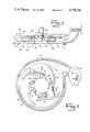
FIG. 1 is a perspective view cutaway of a chopper pump incorporating a preferred embodiment of the present invention;
FIG. 2 is a side view cutaway of a preferred embodiment of the present invention;
FIG. 3 is a top plan view of a preferred embodiment of the prsent invention illustrating the impeller and the cutting teeth;
FIG. 4 is a side view cutaway of an alternate preferred embodiment of the present invention;
FIG. 5 is a top plan view of an alternate preferred embodiment of the present invention illustrating the stationary cutter ring; and
FIG. 6 is a top plan view of another alternate preferred embodiment of the present invention illustrating the stationary cutter ring.
DETAILED DESCRIPTION OF THE PREFERRED EMBODIMENTS
As shown by FIGS. 1 and 2, a centrifugal cutter pump 10 adapted for cutting and pumping an influent liquid 12 containing solids 14 has a suction inlet 16, a discharge outlet 18, a means for driving an impeller 20 and a cutter pump subassembly 22. Legs 24 support the subassembly 22. The outlet 18 has a smooth faced flange 26 adapted to receive an external conduit.
As shown by FIG. 2, the cutter pump subassembly 22 is comprised of a housing 28, an impeller 30 and a stationary cutter 32. The means for driving an impeller 20 is shown in FIG. 1 and consists of a motor 34 connected to a drive shaft 36 which passes through the housing 28 at the shaft opening 38. The shaft 36 is connected to the impeller 30 by passage through the impeller shaft aperture 40. The shaft end has threads 42 to receive a retaining nut 44, thereby securing the drive shaft 36 to the impeller 30.
The housing 28 is provided with a suction side 46, a perimeter 48 and a closed side 50. The closed side 50 is opposite the suction side 46. The perimeter 48 is interposed between the suction side 46 and the closed side 50. The housing 28 thus defines a pump chamber 52. The suction side 46 of the housing 28 is substantially circular and has a suction aperture 54 in the center of the suction side 46. The suction aperture 54 communicates with the suction inlet 16 to permit the influent liquid 12 to pass into the pump chamber 52. The perimeter 48 is provided with a spiral channel 56, also shown in FIG. 1. As illustrated in FIG. 2, the suction side 46 of the housing 28 consists of a removable plate 58. Screws 60 pass through holes 62 in the plate 58 and into threaded apertures 64 in the housing perimeter 48. The plate 58 has a raised inner surface 66, as shown in FIG. 3.
As illustrated in FIGS. 3 and 4, the impeller 30 has a shroud 68 and a plurality of impeller vanes 70. The impeller 30 is operatively associated with the means for driving an impeller 20 so as to be rotatable thereby. An illustration of the means for driving an impeller 20 and its operative association with the impeller 30 is shown in FIGS. 1 and 2. However, it is understood that equivalent means 20 for driving the impeller 30 can be provided, such as through the use of a rotating magnetic field.
As shown in FIG. 5, the impeller shroud 68 is substantially disc shaped and has a circumference 72. The impeller vanes 70 each have a circumferential end 74 and a shearing edge 76. The vanes 70 each extend spirally outward from the shearing edge 76 to the circumferential end 74. The circumferential ends 74 are in contoured relation with the shroud circumference 72, that is, the circumferential end 74 of the impeller vanes 70 are curved so as to coincide with the shroud circumference 72 as viewed from the top. The impeller vanes 70 have their shearing edge 76 oriented inwardly to define a cutting circle 78.
Thus, the vanes 70 are attached to the impeller shroud 68. The impeller 30 is contained in the pump chamber 52 and oriented such that the shroud 68 is interposed between the impeller vanes 70 and the closed side 50 of the housing 28. The impeller vanes 70 project from the shroud 68 toward the suction side 46 of the housing 28.
As shown in FIG. 6, the stationary cutter 32 has an annular base ring 80 and a plurality of cutting teeth 82. The cutting teeth 82 each have at least one blade 84. As shown in FIG. 5, the cutting teeth 82 are each provided with one cutting blade 84. As shown in FIG. 6, the cutting teeth 82 are each provided with two cutting blades 84.
The cutting blades 84 are each equidistant from the center of the annular base ring 80 and thereby define an inner circle 86. The cutting circle 78 defined by the impeller vane shearing edges 76 is slightly larger than the inner circle 86 defined by the blades 84 of the cutter teeth 82. It is understood that the difference between the cutting circle 78 defined by the impeller vane shearing edges 76 and the inner circle 86 defined by the blades 84 of the stationary cutter teeth 82 may be varied in accordance with the skill of the art. In particular, it is noted that a preferred range of the difference between the radii of the inner circle 86 and the cutting circle 78 is between 0.002 and 0.020 inches. The impeller vanes shearing edges 76 are operatively associated with the blades 84 of the stationary cutter teeth 82 to cut solids 14 that are contained in the influent liquid 12.
FIGS. 2 and 3 illustrate a first laternate embodiment of the present invention. As shown by FIG. 2, the chopper pump subassembly 22 is comprised of a housing 28 and an impeller 30. In essence, the stationary cutter 32 shown in the embodiments illustrated in FIGS. 5 and 6 is not present in the embodiment shown in FIG. 2. Rather, the suction side 46 of the housing 28 is provided with a suction aperture 54 in the center of the suction side 46. The suction aperture 54 communicates with the suction inlet 16. A plurality of cutting teeth 82 are radially disposed about the suction aperture 54. The cutting teeth 82 each have at least one blade 84. The blades 84 are equidistant from the center of the suction aperture 54 and define an inner circle 86.
Yet another alternate embodiment of the present invention is shown in FIG. 4. The cutter teeth blades 84 are oriented substantially perpendicularly to the suction aperture 54. The shearing edges 76 of the impeller vane 70 are substantially perpendicular to the shroud 68, thereby associating with the teeth blades 84 coincidentally. Thus, the operative association of the cutter teeth 82 and the impeller vanes 70 occurs in the same direction as the influent liquid flow. Further, the number of impeller vanes 70 is equal to four. The number of cutting teeth 82 is equal to five. Thus, during rotation of the impeller 30, the operative association of the impeller vane shearing edges 76 and the cutter teeth blades 84 occurs singularly, that is, only one shearing edge 76 is in operative proximity with one cutting blade 84 at any instant in time. This embodiment minimizes the power necessary to operate the cutter pump subassembly 22.
Alternatively, it can be seen that the number of impeller vanes 70 can be divisible by or a multiple of and the number of cutting teeth 82. Although such an embodiment would require an increase in the power necessary to operate the chopper pump subassembly 22, it can be seen that vibration would be reduced due to the symmetric simultaneous operative association of the impeller vane shearing edges 76 and the respective cutter teeth blades 84.
Yet another embodiment of the present invention is illustrated by FIG. 3. The shearing edges 76 of the impeller vane 70 can be removable. Securing means 88 for securing the shearing edges 76 to the impeller vanes 70 are provided. As illustrate, the securing means 88 comprises a screw 90 and a threaded hole 92. The cutting blade 84 of the cutting teeth 82 can likewise be removable. Securing means 94 for securing the cutting blades 84 to the cutter teeth 82 are provided. As illustrated, the securing means 94 comprise a screw 96 and a threaded hole 98. By making the cutting blades 84 of the cutter teeth 82 removable, ease of maintenance and repair of the chopper pump subassembly 22 is enhanced.
Thus, the influent liquid 12 containing solids 14 enters the suction inlet 16, passes through the housing suction aperture 54 into the pump chamber 52. The liquid 12 and solids 14 are then drawn outwardly; the solids 14 are cut by the association of the stationary cutter blades 84 and the impeller vanes shearing edges 76. The liquid 12 and solids 14 are then centrifugally drawn outward by the rotation of the impeller vanes 70. The liquid 12 and solids 14 are then conducted through the spiral channel 56 and discharged from the discharge outlet 18. Note that, as shown in these various embodiments, the operative association of the impeller vane shearing edges 76 and the stationary cutter teeth blades 84 is parallel to the axis of rotation of the impeller 30, so that flow characteristics are enhanced. Further, the impeller vane shearing edges 76 and the stationary cutter teeth blades 84 extend approximately equal heights.
Various other changes may be made within the spirit and scope of the invention. Thus, the invention is to be limited only by the following claims and their equivalents.

Claims (24)

I claim:
1. In a centrifugal cutter pump adapted for cutting and pumping an influent liquid containing solids, the cutter pump having a suction inlet, a discharge outlet, means for driving an impeller, and a cutter pump subassembly, an improved cutter pump subassembly comprising, in combination:
a housing,
an impeller, and
a stationary cutter;
said housing defining a pump chamber and having a suction side, a perimeter, and a closed side, said closed side being opposite the suction side, the perimeter being interposed between the suction side and the closed side, the suction side being substantially circular and having a suction aperture in substantially the center of the suction side, said suction aperture communicating with the suction inlet, the perimeter having a spiral channel;
said impeller having a shroud and a plurality of impeller vanes, the impeller operatively associated with the means for driving an impeller so as to be rotatable thereby, the shroud being disc shaped and having a circumference, the impeller vanes each having a circumferential end and a shearing edge, the vanes extending spirally outward and having their circumferential end in contoured relation with the shroud circumference, the vanes having their shearing edge oriented inwardly to define a cutting circle, the vanes being attached to the shroud, the impeller contained in the pump chamber and oriented so that the shroud is interposed between the impeller vanes and the closed side of the housing, the impeller vanes projecting from the shroud toward the suction side of the housing;
the stationary cutter being securably mountable adjacent the housing suction aperture and having an annular base ring and a plurality of cutting teeth, the cutting teeth each having at least one blade, the blades each equidistant from the center of the annular base ring and defining an inner circle, the cutting circle defined by the impeller vane shearing edges being slightly larger than the inner circle defined by the blades of the stationary cutter teeth, said impeller vane shearing edges operatively associated with said blades of the stationary cutter teeth to cut solids contained in the influent liquid, the operative association of the impeller vane shearing edges and the stationary cutter teeth blades being parallel to the axis of rotation of the impeller;
whereby the influent liquid containing solids enters the suction inlet, passes through the housing suction aperture into the pump chamber, is drawn outwardly and cut by the association of the stationary cutter blades and the impeller vane shearing edges, is centrifugally drawn outward by the rotation of the impeller vanes, is conducted through the spiral channel and is discharged from the discharge outlet.
2. The improvement of claim 1 wherein the radius of the cutting circle defined by the impeller vane shearing edges is less than 0.020 inches greater than the radius of the inner circle defined by the stationary cutting teeth blades.
3. The improvement of claim 1 wherein the number of impeller vanes is greater than two and less than eight.
4. The improvement of claim 3 wherein the number of cutting teeth is greater than two and less than eight.
5. The improvement of claim 4 wherein the number of impeller vanes differs from the number of cutting teeth.
6. The improvement of claim 5 wherein the relative number of impeller vanes and cutting teeth is such that the operative association of the vanes and teeth occurs singularly.
7. The improvement of claim 1 wherein the number of cutting teeth is greater than two and less than eight.
8. The improvement of claim 1 wherein each cutting tooth has one blade.
9. The improvement of claim 1 wherein each cutting tooth has two blades.
10. The improvement of claim 1 wherein the shearing edges of the impeller blades are removable and have securing means for securing them to the impeller blades.
11. The improvement of claim 1 wherein the blades of the cutting teeth are removable and have securing means for securing them to the cutting teeth.
12. In a centrifugal cutter pump adapted for cutter and pumping an influent liquid containing solids, the cutter pump having a suction inlet, a discharge outlet, means for driving an impeller, and a cutter pump subassembly, an improved cutter pump subassembly comprising, in combination:
a housing and an impeller;
the housing defining a pump chamber and having a suction side, a perimeter having a spiral channel, and a closed side, said closed side being opposite the suction side, the perimeter being interposed between the suction side and the closed side, the suction side being substantially circular and having a suction aperture in substantially the center of the suction side, said suction aperture communicating with the suction inlet, and a plurality of cutting teeth radially disposed about the suction aperture, the cutting teeth each having at least one blade, the blades each equidistant from the center of the suction aperture and defining an inner circle;
the impeller having a shroud and a plurality of impeller vanes, the impeller operatively associated with the means for driving an impeller so as to be rotatable thereby, the shroud being disc shaped and having a circumference, the impeller vanes each having a circumferential end and a shearing edge, the vanes extending spirally outward and having their circumferential end in contoured relation with the shroud circumference, the vanes having their shearing edge oriented inwardly to define a cutting circle, the vanes being attached to the shroud, the impeller being contained in the pump chamber and oriented so that the shroud is interposed between the impeller vanes and the closed side of the housing, the impeller vanes projecting from the shroud toward the suction side of the housing;
the cutting circle defined by the impeller vane shearing edges being slightly larger than the inner circle defined by the blades of the cutting teeth, said impeller vane shearing edges operatively associated with said blades of the cutting teeth to cut solids contained in the influent liquid, the operative association of the impeller vane shearing edges and the stationary cutter teeth blades being parallel to the axis of rotation of the impeller;
whereby the influent liquid containing solids enters the suction inlet, passes through the housing suction aperture into the pump chamber, is drawn outwardly and cut by the association of the cutting teeth blades and the impeller vane shearing edges, is centrifugally drawn outward by the rotation of the impeller vanes, is conducted through the spiral channel and is discharged from the discharge outlet.
13. The improvement of claim 12 wherein the radius of the cutting circle defined by the impeller vane shearing edges is less than 0.020 inches greater than the radius of the inner circle defined by the stationary cutting teeth blades.
14. The improvement of claim 12 wherein the number of impeller vanes is greater than two and less than eight.
15. The improvement of claim 14 wherein the number of cutting teeth is greater than two and less than eight.
16. The improvement of claim 15 wherein the number of impeller vanes differs from the number of cutting teeth.
17. The improvement of claim 16 wherein the relative number of impeller vanes and cutting teeth is such that the operative association of the vanes and teeth occurs singularly.
18. The improvement of claim 12 wherein the number of cutting teeth is greater than two and less than eight.
19. The improvement of claim 12 wherein each cutting tooth has one blade.
20. The improvement of claim 12 wherein each cutting tooth has two blades.
21. The improvement of claim 12 wherein the shearing edges of the impeller blades are removable and have securing means for securing them to the impeller blades.
22. The improvement of claim 12 wherein the blades of the cutting teeth are removable and having securing means for securing them to the cutting teeth.
23. In a centrifugal cutter pump adapted for cutting and pumping an influent liquid containing solids, the cutter pump having a suction inlet, a discharge outlet, means for driving an impeller, and a cutter pump subassembly, an improved cutter pump subassembly comprising, in combination:
a housing,
an impeller, and
a stationary cutter;
said housing defining a pump chamber and having a suction side, a perimeter, and a closed side, said closed side being opposite the suction side, the perimeter being interposed between the suction side and the closed side, the suction side being substantially circular and having a suction aperture in substantially the center of the suction side, said suction aperture communicating with the suction inlet, the perimeter having a spiral channel;
said impeller having a shroud and a plurality of impeller vanes, the impeller operatively associated with the means for driving an impeller so as to be rotatable thereby, the shroud being disc shaped and having a circumference the impeller vanes each having a circumferential end and a shearing edge, the vanes extending spirally outward and having their circumferential end in contoured relation with the shroud circumference, the vanes having their shearing edge oriented inwardly to define a cutting circle, the vanes being attached ot the shroud, the impeller being contained in the pump chamber and oriented so that the shroud is interposed between the impeller vanes and the closed side of the housing, the impeller vanes projecting from the shroud toward the suction side of the housing;
the stationary cutter being securably mountable adjacent the housing suction aperture and having an annular base ring and a plurality of cutting teeth, the cutting teeth each extending approximately the same height as the shearing edges of the impeller vanes, the cutting teeth each having at least one blade, the blades each equidistant from the center of the annular base ring and defining an inner circle, the cutting circle defined by the impeller vane shearing edges being slightly larger than the inner circle defined by the blades of the stationary cutter teeth, said impeller vane shearing edges operatively associated with said blades of the stationary cutter teeth to cut solids contained in the influent liquid, the operative association of the impeller vane shearing edges and the stationary cutter teeth blades being parallel to the axis of rotation of the impeller;
whereby the influent liquid containing solids enters the suction inlet, passes through the housing suction aperture into the pump chamber, is drawn outwardly and cut by the association of the stationary cutter blades and the impeller vane shearing edges, is centrifugally drawn outward by the rotation of the impeller vanes, is conducted through the spiral channel and is discharged from the discharge outlet.
24. In a centrifugal cutter pump adapted for cutter and pumping an influent liquid containing solids, the cutter pump having a suction inlet, a discharge outlet, means for driving an impeller, and a cutter pump subassembly, an improved cutter pump subassembly comprising, in combination:
a housing and an impeller;
the housing defining a pump chamber and having a suction side, a perimeter having a spiral channel, and a closed side, said closed side being opposite the suction side, the perimeter being interposed between the suction side and the closed side, the suction side being substantially circular and having a suction aperture in substantially the center of the suction side, said suction aperture communicating with the suction inlet, and a plurality of cutting teeth radially disposed about the suction aperture, the cutting teeth each having at least one blade, the blades each equidistant from the center of the suction aperture and defining an inner circle;
the impeller having a shroud and a plurality of impeller vanes, the impeller operatively associated with the means for driving an impeller so as to be rotatable thereby, the shroud being disc shaped and having a circumference, the impeller vanes each having a circumferential end and a shearing edge, the vanes extending spirally outward and having their circumferential end in contoured relation with the shroud circumference, the vanes having their shearing edge oriented inwardly to define a cutting circle, the vanes being attached to the shroud, the impeller being contained in the pump chamber and oriented so that the shroud is interposed between the impeller vanes and the closed side of the housing, the impeller vanes projecting from the shroud toward the suction side of the housing;
the cutting teeth each extending approximately the same height as the shearing edges of the impeller vanes;
the cutting circle defined by the impeller vane shearing edges being slightly larger than the inner circle defined by the blades of the cutting teeth, said impeller vane shearing edges operatively associated with said blades of the cutting teeth to cut solids contained in the influent liquid, the operative association of the impeller vane shearing edges and the stationary cutter teeth blades being parallel to the axis of rotation of the impeller;
whereby the influent liquid containing solids enters the suction inlet, passes through the housing suction aperture into the pump chamber, is drawn outwardly and cut by the association of the cutting teeth blades and the impeller vane shearing edges, is centrifugally drawn outward by the rotation of the impeller vanes, is conducted through the spiral channel and is discharged from the discharge outlet
US07/071,626 1987-07-09 1987-07-09 Cutter pump subassembly Expired - Fee Related US4778336A (en)

Priority Applications (1)

Application Number Priority Date Filing Date Title
US07/071,626 US4778336A (en) 1987-07-09 1987-07-09 Cutter pump subassembly

Applications Claiming Priority (1)

Application Number Priority Date Filing Date Title
US07/071,626 US4778336A (en) 1987-07-09 1987-07-09 Cutter pump subassembly

Publications (1)

Publication Number Publication Date
US4778336A true US4778336A (en) 1988-10-18

Family

ID=22102528

Family Applications (1)

Application Number Title Priority Date Filing Date
US07/071,626 Expired - Fee Related US4778336A (en) 1987-07-09 1987-07-09 Cutter pump subassembly

Country Status (1)

Country Link
US (1) US4778336A (en)

Cited By (43)

* Cited by examiner, † Cited by third party
Publication number Priority date Publication date Assignee Title
US5302082A (en) * 1992-07-09 1994-04-12 Arde, Inc. Improved efficiency grinding pump for slurry
US5451004A (en) * 1993-09-08 1995-09-19 Somat Corporation Integrated waste pulping and liquid extraction system
US5577674A (en) * 1993-09-08 1996-11-26 Somat Corporation Waste pulping and liquid extraction system and method including automatic bag feeding
US6190121B1 (en) 1999-02-12 2001-02-20 Hayward Gordon Limited Centrifugal pump with solids cutting action
US6224331B1 (en) 1999-02-12 2001-05-01 Hayward Gordon Limited Centrifugal pump with solids cutting action
US6386751B1 (en) * 1997-10-24 2002-05-14 Diffusion Dynamics, Inc. Diffuser/emulsifier
US6629814B2 (en) 2000-08-22 2003-10-07 Henry Filters, Inc. Low profile pump
US20040146416A1 (en) * 2001-06-13 2004-07-29 Burgess Kevin Edward Apparatus for use in slurry pumps
EP1584820A1 (en) * 2004-04-07 2005-10-12 Frideco AG Mixed flow pump
US20060266856A1 (en) * 2005-05-25 2006-11-30 Shaw James G Cutting ring element for a centrifugal chopper pump
US20080146679A1 (en) * 2006-10-25 2008-06-19 Revalesio Corporation Methods of therapeutic treatment of eyes and other human tissues using an oxygen-enriched solution
WO2009032299A1 (en) * 2007-09-04 2009-03-12 Envirotech Pumpsystems, Inc. Wear plate for a centrifugal pump
US20090087317A1 (en) * 2007-10-02 2009-04-02 Keener Robert M Blade Set for Masserating Effluent Water in a Sewage Pump
US7654728B2 (en) 1997-10-24 2010-02-02 Revalesio Corporation System and method for therapeutic application of dissolved oxygen
US7770814B2 (en) 1997-10-24 2010-08-10 Revalesio Corporation System and method for irrigating with aerated water
US7832920B2 (en) 2006-10-25 2010-11-16 Revalesio Corporation Mixing device for creating an output mixture by mixing a first material and a second material
US7887698B2 (en) 1997-10-24 2011-02-15 Revalesio Corporation Diffuser/emulsifier for aquaculture applications
US20110049280A1 (en) * 2007-05-14 2011-03-03 Daley Paul J Cutting wheels for grinder pumps
US20130121811A1 (en) * 2011-11-16 2013-05-16 Walter James Cuppetelli Centrifugal chopper pump
US8445546B2 (en) 2006-10-25 2013-05-21 Revalesio Corporation Electrokinetically-altered fluids comprising charge-stabilized gas-containing nanostructures
US8609148B2 (en) 2006-10-25 2013-12-17 Revalesio Corporation Methods of therapeutic treatment of eyes
US8617616B2 (en) 2006-10-25 2013-12-31 Revalesio Corporation Methods of wound care and treatment
US8784897B2 (en) 2006-10-25 2014-07-22 Revalesio Corporation Methods of therapeutic treatment of eyes
US8784898B2 (en) 2006-10-25 2014-07-22 Revalesio Corporation Methods of wound care and treatment
US8815292B2 (en) 2009-04-27 2014-08-26 Revalesio Corporation Compositions and methods for treating insulin resistance and diabetes mellitus
US8980325B2 (en) 2008-05-01 2015-03-17 Revalesio Corporation Compositions and methods for treating digestive disorders
US8979476B2 (en) 2010-07-21 2015-03-17 ITT Manfacturing Enterprises, LLC. Wear reduction device for rotary solids handling equipment
US20150118024A1 (en) * 2013-10-24 2015-04-30 Bryce Thiel Centrifugal pump with self-cleaning wear plate
WO2015144307A1 (en) * 2014-03-27 2015-10-01 Wilo Se Centrifugal pump comprising a cutting device
US9198929B2 (en) 2010-05-07 2015-12-01 Revalesio Corporation Compositions and methods for enhancing physiological performance and recovery time
US9222484B2 (en) 2012-04-27 2015-12-29 Weir Minerals Australia, Ltd. Centrifugal pump casing with offset discharge
JPWO2014073140A1 (en) * 2012-11-08 2016-09-08 新明和工業株式会社 Centrifugal pump
US9475059B2 (en) 2013-03-15 2016-10-25 Pentair Flow Technologies, Llc Cutting blade assembly
US9492404B2 (en) 2010-08-12 2016-11-15 Revalesio Corporation Compositions and methods for treatment of taupathy
WO2016201436A1 (en) * 2015-06-11 2016-12-15 Eco-Flo Products, Inc. d/b/a Ashland Pump Hybrid radial axial cutter
US9523090B2 (en) 2007-10-25 2016-12-20 Revalesio Corporation Compositions and methods for treating inflammation
US9745567B2 (en) 2008-04-28 2017-08-29 Revalesio Corporation Compositions and methods for treating multiple sclerosis
US20170321701A1 (en) * 2013-01-11 2017-11-09 Liberty Pumps, Inc. Liquid pump
US10125359B2 (en) 2007-10-25 2018-11-13 Revalesio Corporation Compositions and methods for treating inflammation
US11161121B2 (en) 2019-05-10 2021-11-02 Jung Pumpen Gmbh Cutting blade assembly
US11512701B2 (en) * 2020-11-10 2022-11-29 Chengli Li Cutting system for a grinding pump and related grinding pump
US11560894B2 (en) 2016-04-26 2023-01-24 Pentair Flow Technologies, Llc Cutting assembly for a chopper pump
CN116753177A (en) * 2023-08-16 2023-09-15 浙江丰球克瑞泵业有限公司 Cutting pump with anti-jamming function

Citations (25)

* Cited by examiner, † Cited by third party
Publication number Priority date Publication date Assignee Title
BE538150A (en) *
US1287920A (en) * 1917-02-01 1918-12-17 Oswald Duda Centrifugal pump.
US2323382A (en) * 1941-04-21 1943-07-06 Dibovsky Victor Vladimirovitch Rotary blower
GB608741A (en) * 1946-05-09 1948-09-20 Wilfred Nathan Waterworth Pier Disintegrating unit for sewage or the like
US3096718A (en) * 1961-12-12 1963-07-09 Conard Kenner Trash cutter for a pump
US3155046A (en) * 1962-04-23 1964-11-03 Vaughan Co Centrifugal nonclogging pump
US3318248A (en) * 1964-06-03 1967-05-09 Harry M Roberts Disintegrating type sewage disposal system
US3340812A (en) * 1964-07-01 1967-09-12 Schlesiger & Co K G Centrifugal pump
US3388671A (en) * 1965-07-15 1968-06-18 Cities Service Res & Dev Co Centrifugal pump
US3444818A (en) * 1966-10-10 1969-05-20 Robert W Sutton Centrifugal pump
US3446151A (en) * 1967-06-08 1969-05-27 Osby Pump Ind Submersible centrifugal pump
US3447475A (en) * 1967-01-09 1969-06-03 Albert Blum Centrifugal pump
US3560106A (en) * 1969-02-13 1971-02-02 Nils Johan Sahlstrom Slurry handling pump
US3627280A (en) * 1970-01-14 1971-12-14 Viktor Mironovich Fridman Apparatus for mixing and dispersing liquids and liquids with solids
US3692422A (en) * 1971-01-18 1972-09-19 Pierre Mengin Ets Shearing pump
US3786996A (en) * 1972-03-20 1974-01-22 Tec Group Axial flow unit
US3866841A (en) * 1972-09-11 1975-02-18 Elepon Technical Center Submersible pump equipped with cutter
US3915394A (en) * 1974-03-21 1975-10-28 Bendix Corp Centrifugal pump including contamination chopping means
US3973866A (en) * 1975-01-02 1976-08-10 Vaughan Co., Inc. Centrifugal chopping slurry pump
US4011027A (en) * 1974-09-23 1977-03-08 Escher Wyss G.M.B.H. Stain removal apparatus
US4145008A (en) * 1977-08-22 1979-03-20 The Gorman-Rupp Company Waste material pumping apparatus
US4361414A (en) * 1980-07-23 1982-11-30 Banyaszati Kutato Intezet Equipment for the delivery of slurries and for refinement during delivery
US4402648A (en) * 1981-08-31 1983-09-06 A. O. Smith Harvestore Products, Inc. Chopper pump
US4540334A (en) * 1982-12-22 1985-09-10 Staehle Martin Open-type centrifugal pump with single-blade impeller
US4594052A (en) * 1982-02-08 1986-06-10 A. Ahlstrom Osakeyhtio Centrifugal pump for liquids containing solid material

Patent Citations (25)

* Cited by examiner, † Cited by third party
Publication number Priority date Publication date Assignee Title
BE538150A (en) *
US1287920A (en) * 1917-02-01 1918-12-17 Oswald Duda Centrifugal pump.
US2323382A (en) * 1941-04-21 1943-07-06 Dibovsky Victor Vladimirovitch Rotary blower
GB608741A (en) * 1946-05-09 1948-09-20 Wilfred Nathan Waterworth Pier Disintegrating unit for sewage or the like
US3096718A (en) * 1961-12-12 1963-07-09 Conard Kenner Trash cutter for a pump
US3155046A (en) * 1962-04-23 1964-11-03 Vaughan Co Centrifugal nonclogging pump
US3318248A (en) * 1964-06-03 1967-05-09 Harry M Roberts Disintegrating type sewage disposal system
US3340812A (en) * 1964-07-01 1967-09-12 Schlesiger & Co K G Centrifugal pump
US3388671A (en) * 1965-07-15 1968-06-18 Cities Service Res & Dev Co Centrifugal pump
US3444818A (en) * 1966-10-10 1969-05-20 Robert W Sutton Centrifugal pump
US3447475A (en) * 1967-01-09 1969-06-03 Albert Blum Centrifugal pump
US3446151A (en) * 1967-06-08 1969-05-27 Osby Pump Ind Submersible centrifugal pump
US3560106A (en) * 1969-02-13 1971-02-02 Nils Johan Sahlstrom Slurry handling pump
US3627280A (en) * 1970-01-14 1971-12-14 Viktor Mironovich Fridman Apparatus for mixing and dispersing liquids and liquids with solids
US3692422A (en) * 1971-01-18 1972-09-19 Pierre Mengin Ets Shearing pump
US3786996A (en) * 1972-03-20 1974-01-22 Tec Group Axial flow unit
US3866841A (en) * 1972-09-11 1975-02-18 Elepon Technical Center Submersible pump equipped with cutter
US3915394A (en) * 1974-03-21 1975-10-28 Bendix Corp Centrifugal pump including contamination chopping means
US4011027A (en) * 1974-09-23 1977-03-08 Escher Wyss G.M.B.H. Stain removal apparatus
US3973866A (en) * 1975-01-02 1976-08-10 Vaughan Co., Inc. Centrifugal chopping slurry pump
US4145008A (en) * 1977-08-22 1979-03-20 The Gorman-Rupp Company Waste material pumping apparatus
US4361414A (en) * 1980-07-23 1982-11-30 Banyaszati Kutato Intezet Equipment for the delivery of slurries and for refinement during delivery
US4402648A (en) * 1981-08-31 1983-09-06 A. O. Smith Harvestore Products, Inc. Chopper pump
US4594052A (en) * 1982-02-08 1986-06-10 A. Ahlstrom Osakeyhtio Centrifugal pump for liquids containing solid material
US4540334A (en) * 1982-12-22 1985-09-10 Staehle Martin Open-type centrifugal pump with single-blade impeller

Non-Patent Citations (9)

* Cited by examiner, † Cited by third party
Title
Advertisement for Enpo Pump Company pumps. *
Advertisement for FE Myers pump showing replaceable grinder impellar and shredding ring. *
Advertisement for Gorman Rupp brand grinder pumps. *
Advertisement for Gorman-Rupp brand grinder pumps.
Advertisement for Hydr O Grind series pumps. *
Advertisement for Hydr-O-Grind series pumps.
Advertisement for LCC series chopper pumps. *
Advertisement for SGV 201 204 series pumps from Peabody Barnes. *
Advertisement for SGV 201-204 series pumps from Peabody Barnes.

Cited By (77)

* Cited by examiner, † Cited by third party
Publication number Priority date Publication date Assignee Title
US5302082A (en) * 1992-07-09 1994-04-12 Arde, Inc. Improved efficiency grinding pump for slurry
US5451004A (en) * 1993-09-08 1995-09-19 Somat Corporation Integrated waste pulping and liquid extraction system
US5577674A (en) * 1993-09-08 1996-11-26 Somat Corporation Waste pulping and liquid extraction system and method including automatic bag feeding
US7770814B2 (en) 1997-10-24 2010-08-10 Revalesio Corporation System and method for irrigating with aerated water
US9034195B2 (en) 1997-10-24 2015-05-19 Revalesio Corporation Diffuser/emulsifier for aquaculture applications
US6386751B1 (en) * 1997-10-24 2002-05-14 Diffusion Dynamics, Inc. Diffuser/emulsifier
US7806584B2 (en) 1997-10-24 2010-10-05 Revalesio Corporation Diffuser/emulsifier
US8349191B2 (en) 1997-10-24 2013-01-08 Revalesio Corporation Diffuser/emulsifier for aquaculture applications
US7887698B2 (en) 1997-10-24 2011-02-15 Revalesio Corporation Diffuser/emulsifier for aquaculture applications
US7654728B2 (en) 1997-10-24 2010-02-02 Revalesio Corporation System and method for therapeutic application of dissolved oxygen
US6224331B1 (en) 1999-02-12 2001-05-01 Hayward Gordon Limited Centrifugal pump with solids cutting action
US6190121B1 (en) 1999-02-12 2001-02-20 Hayward Gordon Limited Centrifugal pump with solids cutting action
US20030194314A1 (en) * 2000-08-22 2003-10-16 Mcewen Stephen N. Low profile pump
US6629814B2 (en) 2000-08-22 2003-10-07 Henry Filters, Inc. Low profile pump
US6951445B2 (en) 2001-06-13 2005-10-04 Weir Warman Ltd Apparatus for use in slurry pumps
US20040146416A1 (en) * 2001-06-13 2004-07-29 Burgess Kevin Edward Apparatus for use in slurry pumps
US7510368B2 (en) 2004-04-07 2009-03-31 Frideco Ag Screw-centrifugal pump
CN100419271C (en) * 2004-04-07 2008-09-17 弗里德科股份公司 Screw-centrifugal pump
US20070172345A1 (en) * 2004-04-07 2007-07-26 Martin Stahle Screw-centrifugal pump
WO2005098237A1 (en) * 2004-04-07 2005-10-20 Frideco Ag Screw-centrifugal pump
EP1584820A1 (en) * 2004-04-07 2005-10-12 Frideco AG Mixed flow pump
US20070125893A1 (en) * 2005-05-25 2007-06-07 Shaw James G Cutting ring element for a centrifugal chopper pump
US7584916B2 (en) * 2005-05-25 2009-09-08 Envirotech Pumpsystems, Inc. Cutting ring element for a centrifugal chopper pump
US20060266856A1 (en) * 2005-05-25 2006-11-30 Shaw James G Cutting ring element for a centrifugal chopper pump
US8591957B2 (en) 2006-10-25 2013-11-26 Revalesio Corporation Methods of therapeutic treatment of eyes and other human tissues using an oxygen-enriched solution
US8784897B2 (en) 2006-10-25 2014-07-22 Revalesio Corporation Methods of therapeutic treatment of eyes
US9402803B2 (en) 2006-10-25 2016-08-02 Revalesio Corporation Methods of wound care and treatment
US9004743B2 (en) 2006-10-25 2015-04-14 Revalesio Corporation Mixing device for creating an output mixture by mixing a first material and a second material
US9511333B2 (en) 2006-10-25 2016-12-06 Revalesio Corporation Ionic aqueous solutions comprising charge-stabilized oxygen-containing nanobubbles
US7919534B2 (en) 2006-10-25 2011-04-05 Revalesio Corporation Mixing device
US9512398B2 (en) 2006-10-25 2016-12-06 Revalesio Corporation Ionic aqueous solutions comprising charge-stabilized oxygen-containing nanobubbles
US8962700B2 (en) 2006-10-25 2015-02-24 Revalesio Corporation Electrokinetically-altered fluids comprising charge-stabilized gas-containing nanostructures
US8784898B2 (en) 2006-10-25 2014-07-22 Revalesio Corporation Methods of wound care and treatment
US8410182B2 (en) 2006-10-25 2013-04-02 Revalesio Corporation Mixing device
US20080146679A1 (en) * 2006-10-25 2008-06-19 Revalesio Corporation Methods of therapeutic treatment of eyes and other human tissues using an oxygen-enriched solution
US8445546B2 (en) 2006-10-25 2013-05-21 Revalesio Corporation Electrokinetically-altered fluids comprising charge-stabilized gas-containing nanostructures
US8449172B2 (en) 2006-10-25 2013-05-28 Revalesio Corporation Mixing device for creating an output mixture by mixing a first material and a second material
US8470893B2 (en) 2006-10-25 2013-06-25 Revalesio Corporation Electrokinetically-altered fluids comprising charge-stabilized gas-containing nanostructures
US7832920B2 (en) 2006-10-25 2010-11-16 Revalesio Corporation Mixing device for creating an output mixture by mixing a first material and a second material
US8597689B2 (en) 2006-10-25 2013-12-03 Revalesio Corporation Methods of wound care and treatment
US8609148B2 (en) 2006-10-25 2013-12-17 Revalesio Corporation Methods of therapeutic treatment of eyes
US8617616B2 (en) 2006-10-25 2013-12-31 Revalesio Corporation Methods of wound care and treatment
US8342434B2 (en) * 2007-05-14 2013-01-01 Environment One Corporation Cutting wheels for grinder pumps
US20110049280A1 (en) * 2007-05-14 2011-03-03 Daley Paul J Cutting wheels for grinder pumps
WO2009032299A1 (en) * 2007-09-04 2009-03-12 Envirotech Pumpsystems, Inc. Wear plate for a centrifugal pump
AU2008296843B2 (en) * 2007-09-04 2011-08-18 Envirotech Pumpsystems, Inc. Wear plate for a centrifugal pump
US20090232639A1 (en) * 2007-09-04 2009-09-17 Arnold Kim M Wear plate for a centrifugal pump
US20090087317A1 (en) * 2007-10-02 2009-04-02 Keener Robert M Blade Set for Masserating Effluent Water in a Sewage Pump
US7841827B2 (en) * 2007-10-02 2010-11-30 Keener Robert M Blade set for masserating effluent water in a sewage pump
US10125359B2 (en) 2007-10-25 2018-11-13 Revalesio Corporation Compositions and methods for treating inflammation
US9523090B2 (en) 2007-10-25 2016-12-20 Revalesio Corporation Compositions and methods for treating inflammation
US9745567B2 (en) 2008-04-28 2017-08-29 Revalesio Corporation Compositions and methods for treating multiple sclerosis
US8980325B2 (en) 2008-05-01 2015-03-17 Revalesio Corporation Compositions and methods for treating digestive disorders
US9272000B2 (en) 2009-04-27 2016-03-01 Revalesio Corporation Compositions and methods for treating insulin resistance and diabetes mellitus
US9011922B2 (en) 2009-04-27 2015-04-21 Revalesio Corporation Compositions and methods for treating insulin resistance and diabetes mellitus
US8815292B2 (en) 2009-04-27 2014-08-26 Revalesio Corporation Compositions and methods for treating insulin resistance and diabetes mellitus
US9198929B2 (en) 2010-05-07 2015-12-01 Revalesio Corporation Compositions and methods for enhancing physiological performance and recovery time
US8979476B2 (en) 2010-07-21 2015-03-17 ITT Manfacturing Enterprises, LLC. Wear reduction device for rotary solids handling equipment
US9492404B2 (en) 2010-08-12 2016-11-15 Revalesio Corporation Compositions and methods for treatment of taupathy
US20130121811A1 (en) * 2011-11-16 2013-05-16 Walter James Cuppetelli Centrifugal chopper pump
US8657564B2 (en) * 2011-11-16 2014-02-25 Walter James Cuppetelli Centrifugal chopper pump
US9222484B2 (en) 2012-04-27 2015-12-29 Weir Minerals Australia, Ltd. Centrifugal pump casing with offset discharge
JPWO2014073140A1 (en) * 2012-11-08 2016-09-08 新明和工業株式会社 Centrifugal pump
US20170321701A1 (en) * 2013-01-11 2017-11-09 Liberty Pumps, Inc. Liquid pump
US10267312B2 (en) * 2013-01-11 2019-04-23 Liberty Pumps, Inc. Liquid pump
US10670020B2 (en) 2013-03-15 2020-06-02 Pentair Flow Technologies, Llc Cutting blade assembly
US9475059B2 (en) 2013-03-15 2016-10-25 Pentair Flow Technologies, Llc Cutting blade assembly
US11655821B2 (en) 2013-03-15 2023-05-23 Pentair Flow Technologies, Llc Cutting blade assembly
US20150118024A1 (en) * 2013-10-24 2015-04-30 Bryce Thiel Centrifugal pump with self-cleaning wear plate
WO2015144307A1 (en) * 2014-03-27 2015-10-01 Wilo Se Centrifugal pump comprising a cutting device
US10316846B2 (en) 2015-06-11 2019-06-11 Eco-Flo Products, Inc. Hybrid radial axial cutter
WO2016201436A1 (en) * 2015-06-11 2016-12-15 Eco-Flo Products, Inc. d/b/a Ashland Pump Hybrid radial axial cutter
US11560894B2 (en) 2016-04-26 2023-01-24 Pentair Flow Technologies, Llc Cutting assembly for a chopper pump
US11161121B2 (en) 2019-05-10 2021-11-02 Jung Pumpen Gmbh Cutting blade assembly
US11512701B2 (en) * 2020-11-10 2022-11-29 Chengli Li Cutting system for a grinding pump and related grinding pump
CN116753177A (en) * 2023-08-16 2023-09-15 浙江丰球克瑞泵业有限公司 Cutting pump with anti-jamming function
CN116753177B (en) * 2023-08-16 2023-11-10 浙江丰球克瑞泵业有限公司 Cutting pump with anti-jamming function

Similar Documents

Publication Publication Date Title
US4778336A (en) Cutter pump subassembly
US2958293A (en) Solids pump
US10267312B2 (en) Liquid pump
US4981413A (en) Pump for and method of separating gas from a fluid to be pumped
US7037069B2 (en) Impeller and wear plate
US4108386A (en) Grinder pump
EP0120178B1 (en) Centrifugal pump for pumping liquids containing solid bodies
US5209641A (en) Apparatus for fluidizing, degassing and pumping a suspension of fibrous cellulose material
US3447475A (en) Centrifugal pump
US4592700A (en) Vortex pump
US2013455A (en) Pump
US3650481A (en) Grinder pump
US7766605B2 (en) Centrifugal pump
CA2856861A1 (en) Flow directing device for delivering material to an impeller
US4697746A (en) Grinder pump
US3340812A (en) Centrifugal pump
US8128360B2 (en) Vortex pump with splitter blade impeller
EP1815144B1 (en) Impeller wheel
US3444818A (en) Centrifugal pump
US5516261A (en) Unchokable centrifugal pump
US4614478A (en) Pump impeller
US3776657A (en) Self-priming high-pressure pump
JPH04279795A (en) Pump
CN213775708U (en) Cutting system of grinding pump and grinding pump
US11512701B2 (en) Cutting system for a grinding pump and related grinding pump

Legal Events

Date Code Title Description
AS Assignment

Owner name: WEIL PUMP COMPANY

Free format text: ASSIGNMENT OF ASSIGNORS INTEREST.;ASSIGNOR:HUSAIN, IQBAL;REEL/FRAME:004746/0324

Effective date: 19870708

FEPP Fee payment procedure

Free format text: PAT HOLDER CLAIMS SMALL ENTITY STATUS - SMALL BUSINESS (ORIGINAL EVENT CODE: SM02); ENTITY STATUS OF PATENT OWNER: SMALL ENTITY

REFU Refund

Free format text: REFUND OF EXCESS PAYMENTS PROCESSED (ORIGINAL EVENT CODE: R169); ENTITY STATUS OF PATENT OWNER: SMALL ENTITY

FPAY Fee payment

Year of fee payment: 4

FPAY Fee payment

Year of fee payment: 4

REMI Maintenance fee reminder mailed
LAPS Lapse for failure to pay maintenance fees
FP Lapsed due to failure to pay maintenance fee

Effective date: 19961023

STCH Information on status: patent discontinuation

Free format text: PATENT EXPIRED DUE TO NONPAYMENT OF MAINTENANCE FEES UNDER 37 CFR 1.362