US4836308A - Highly accurate platform weighing system - Google Patents
Highly accurate platform weighing system Download PDFInfo
- Publication number
- US4836308A US4836308A US07/177,183 US17718388A US4836308A US 4836308 A US4836308 A US 4836308A US 17718388 A US17718388 A US 17718388A US 4836308 A US4836308 A US 4836308A
- Authority
- US
- United States
- Prior art keywords
- weight
- calibration
- load
- monitored
- count
- Prior art date
- Legal status (The legal status is an assumption and is not a legal conclusion. Google has not performed a legal analysis and makes no representation as to the accuracy of the status listed.)
- Expired - Lifetime
Links
Images


Classifications
-
- G—PHYSICS
- G01—MEASURING; TESTING
- G01G—WEIGHING
- G01G19/00—Weighing apparatus or methods adapted for special purposes not provided for in the preceding groups
- G01G19/02—Weighing apparatus or methods adapted for special purposes not provided for in the preceding groups for weighing wheeled or rolling bodies, e.g. vehicles
- G01G19/07—Weighing apparatus or methods adapted for special purposes not provided for in the preceding groups for weighing wheeled or rolling bodies, e.g. vehicles for weighing aircraft
-
- G—PHYSICS
- G01—MEASURING; TESTING
- G01G—WEIGHING
- G01G23/00—Auxiliary devices for weighing apparatus
- G01G23/01—Testing or calibrating of weighing apparatus
-
- G—PHYSICS
- G01—MEASURING; TESTING
- G01G—WEIGHING
- G01G5/00—Weighing apparatus wherein the balancing is effected by fluid action
- G01G5/04—Weighing apparatus wherein the balancing is effected by fluid action with means for measuring the pressure imposed by the load on a liquid
- G01G5/06—Weighing apparatus wherein the balancing is effected by fluid action with means for measuring the pressure imposed by the load on a liquid with electrical indicating means
Definitions
- the present invention generally relates to weight measurement systems. More specifically, the present invention relates to such systems which weigh heavy objects, such as aircraft.
- Aircraft and other large objects must occasionally be weighed.
- the weighing procedure typically utilizes a plurality of load cells upon which the entire weight of the object collectively rests.
- the load cells couple to transducers which provide electrical signals. These electrical signals may be measured, and the electrical measurements may be converted into a weight.
- the sum of weights resulting from outputs measured at each of the plurality of load cells equals the total weight of the object.
- the individual weights are useful in calculating center of gravity parameters.
- a platform weighing system provides one conventional solution to the problems posed in weighing aircraft or other large objects.
- the object is rolled onto a plurality of platforms.
- one platform resides under each of the object's wheels.
- Each platform contains at least one load cell which senses weight applied to the platform.
- platform weighing systems tend to operate in electrically noisy environments and over a wide variation in temperature.
- the electrical circuits used to measure load cell output signals in conventional platform weighing systems are so influenced by noise, the environment, temperature, and the like, that they fail to achieve acceptable accuracies.
- Another advantage of the present invention concerns providing an improved architecture for electrical circuits in a platform weighing system so that highly accurate and repeatable weight measurements result.
- the above and other advantages of the present invention are carried out in one form by a system that indicates an object's weight.
- the system includes a device which senses the object's weight and provides an analog signal which has an amplitude proportional to the weight.
- a conversion device couples to the sensing device so that the analog signal is converted into an oscillation signal having a frequency which is proportional to the weight.
- a counter couples to the conversion device to monitor the oscillation signal and provide a monitored load count which is proportional to the weight.
- a computing device couples to the counter and converts the monitored load count into a weight code which describes the weight.
- a display also couples to the computing device, receives the weight code, and converts the weight code into a humanly perceptible indication of the weight.
- a memory couples to the computing device.
- the memory stores a program which the computing device executes and a table that contains a predetermined number of calibration load counts. Each of the calibration load counts has a calibration weight associated therewith.
- the program stored within the memory is configured to cause the computing device to generate the weight code based upon an interpolation between two of the calibration weights. The two calibration weights used in the interpolation are selected so that one of the weights is greater than the monitored load count and the other of the weights is less than the monitored load count.
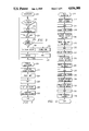
- FIG. 1 shows a schematic block diagram of a digital portion of hardware utilized in a preferred embodiment of a platform weighing system constructed according to the present invention
- FIG. 2 shows a schematic block diagram of an analog portion of hardware utilized in the preferred embodiment of the present invention
- FIG. 3 shows a simplified flow chart of tasks performed by a microprocessor in the preferred embodiment of the present invention when the microprocessor executes a program in a foreground mode;
- FIG. 4 shows a simplified flow chart of a Collect Load Count routine shown in FIG. 3;
- FIG. 5 shows a simplified flow chart of an Auto-Calibration routine shown in FIG. 3;
- FIG. 6 shows a simplified flow chart of a Calculate Weight routine shown in FIG. 3;
- FIG. 7 shows a simplified flow chart of tasks performed by the microprocessor in the preferred embodiment of the present invention when the microprocessor executes a program in an Interrupt mode
- FIG. 8 shows a simplified flow chart of tasks performed by the microprocessor in the preferred embodiment of the present invention when the microprocessor executes a program in a Calibrate mode.
- Counter 22 and timer 24 represent structurally similar programmable circuits which are programmed in the preferred embodiment to operate differently.
- counter 22 is programmed to begin counting transitions of an external signal at an initial count, which is typically zero, and to continue counting until counter 22 is stopped by computing circuits 18.
- the count contained within counter 22 is readable at any time by computing circuits 18.
- timer 24 is programmed to establish predetermined durations for system 10. For example, timer 24 counts a predetermined clock frequency from an initial count to a terminal count. When timer 24 achieves the terminal count, timer 24 stops counting and interrupts microprocessor 16.
- the initial counting point is programmable to establish the duration.
- microprocessor 16 includes substantially conventional circuits for the purpose of the present invention and that other types of computing devices may be adapted for use in the present invention, even though such devices may not include counter 22, timer 24, and RAM 20 within a single integrated circuit.
- digital portion 12 of system 10 includes a clock circuit 26 which has a first output that couples to a clock input of microprocessor 16. This first output provides timing signals for computing circuits 18 of microprocessor 16 and for the operation of timer 24 of microprocessor 16.
- clock circuit 26 has a second output which provides a frequency reference signal at a node 28 for a voltage-to-frequency converter, which is discussed below in connection with FIG. 2.
- An oscillation signal generated by this voltage-to-frequency converter is provided at a node 30 which couples to a count input of counter 22 on microprocessor 16.
- parallel output data ports P0-P3 of microprocessor 16 couple to nodes 32, 34, 36, and 38, respectively, to provide programmable control bits for analog portion 14 of system 10.
- Digital portion 12 of system 10 additionally includes a data/address bus 40 which couples to address and data input and output pins of microprocessor 16.
- Microprocessor 16 communicates with other devices in digital portion 12 of system 10 through bus 40. Consequently, various control circuits and address decoding circuits, which are not shown in FIG. 1, are utilized to decode addresses provided by microprocessor 16 so that only a selected one of these devices is accessed during a memory or input/output operation of microprocessor 16.
- control in decoding circuits are of a conventional design in the preferred embodiment of the present invention and are not discussed further herein.
- Nonvolatile RAM 42 retains data stored therein, even though power applied to system 10 may be removed.
- EEPROM electrically erasable, programmable, read only memory
- microprocessor 16 communicates with a read only memory (ROM) 44 through bus 40.
- ROM read only memory
- a programmable ROM (PROM) or an erasable PROM (EPROM) may serve as ROM 44.
- ROM 44 contains computer programs that microprocessor 16 executes, tables that are utilized by the programs which microprocessor 16 executes, and other data which do not change through the operation of system 10.
- Microprocessor 16 additionally communicates over bus 40 with a display 46.
- Display 46 has a data input which couples to bus 40.
- Display 46 internally latches data written thereto by microprocessor 16.
- display 46 represents a liquid crystal display (LCD) which displays up to 16 alpha-numeric characters.
- a predetermined digital code such as a well-known ASCII code, describes each character to be displayed. After microprocessor 16 writes such codes to display 46 in a predetermined order, the corresponding characters are then observable or perceptible on display 46 by a human user of system 10.
- Display 46 additionally incorporates a contrast input.
- Microprocessor 16 controls a signal applied at this contrast input.
- a latch 48 has an input which couples to bus 40 so that microprocessor 16 may write data into latch 48.
- First, second, third, and fourth output bits of latch 48 couple through resistors 50a, 50b, 50c, and 50d, respectively, to a signal input node of an amplifier circuit 52.
- resistor 50b exhibits twice the resistance of resistor 50a
- resistor 50c exhibits twice the resistance of resistor 50b
- resistor 50d exhibits twice the resistance of resistor 50c.
- the signal input node of amplifier circuit 52 additionally couples through a resistor 54 to a terminal 56, which supplies one of either a positive, negative, or ground supply voltage.
- An output of amplifier circuit 52 couples to the contrast input of display 46.
- microprocessor 16 writes four bit data codes to latch 48 to program the voltage supplied to the contrast input of display 46.
- Digital portion 12 of system 10 additionally includes an interrupt structure.
- a manually operable switch 58 has a first node which couples to a terminal 60 and a second node which couples to a first input bit of a buffer 62.
- a second manually operable switch 64 has a first node which couples to a terminal 66 and a second node which couples to a second input bit of buffer 62.
- Terminals 60 and 66 couple to one of a positive voltage or ground
- the second nodes of switches 58 and 64 additionally couple through resistors (not shown) to the other of a positive voltage or ground.
- a terminal 68 which provides a signal generated by other portions of system 10, such as low voltage indication circuits (not shown), couples to a third input bit of buffer 62.
- buffer 62 couples to respective inputs of a gate 70 which performs a logical OR function, and an output of gate 70 couples to an interrupt input of microprocessor 16.
- buffer 62 has an output which couples to bus 40.
- one active interrupt signal is supplied at terminal 68 when battery voltage drops a first predetermined amount, such as from 0.6 to 1.0 volt when a 12 volt battery is being monitored.
- System 10 causes display 46 to occasionally flash a message stating "Low Battery” when this interrupt signal occurs.
- a second interrupt signal is supplied at terminal 68 when battery voltage drops below a second predetermined amount, such as greater than 1.0 volt. In this case, display 46 continually displays a "Low Battery” message.
- the activation of switch 58 causes system 10 to perform a contrast adjustment function, and the activation of switch 64 causes system 10 to perform a zeroing function.
- An active signal is provided at the interrupt input of microprocessor 16 upon the activation of switches 58 or 60 or whenever an active signal is presented on terminal 68.
- microprocessor 16 detects the occurrence of an interrupt signal, microprocessor 16 performs a read operation at buffer 62 to isolate the source of the interrupting signal.
- System 10 communicates with devices external to system 10.
- Microprocessor 16 contains a serial out terminal which couples to an input of a first port of an interface circuit 72.
- a first port output of interface circuit 72 couples to a serial input of microprocessor 16.
- Second port input and outputs of interface circuit 72 couple to a serial communication bus 74.
- Microprocessor 16 performs serial data communications through the serial out and serial in terminals of microprocessor 16.
- Interface circuit 72 transforms voltage levels between the serial signals received from and applied to microprocessor 16 on one hand and serial communication bus 74 on the other.
- the serial data communication occurring on serial data bus 74 conforms to a standard communication protocol, such as the well known RS-232C standard
- Serial data bus 74 may couple to a hand held terminal 76 which, in the preferred embodiment, contains a display and a plurality of keypads. Hand held terminal 76 is utilized primarily to calibrate system 10.
- system 10 may communicate over serial data bus 74 to a central computer 78B.
- Interface circuit 72 of system 10 may be configured either so that several of systems 10 couple to a single central computer 78 through individual busses 74, or so that several of systems 10 couple through a common drop line bus 74 to central computer 78.
- Central computer 78 may be utilized to perform the same functions as hand held terminal 76.
- central computer 78B may control a plurality of systems 10 in an integrated weighing system which, for example, makes center of gravity calculations when an aircraft is being weighted.
- FIG. 2 shows a schematic block diagram of analog portion 14 of system 10.
- analog portion 14 contains four load cells 80a, 80b, 80c, and 80d.
- Load cells 80a-80d are pressure type, hydraulic sensing load cells, which are known to those skilled in the art.
- One example of such a load cell is shown in U.S. Pat. No. 4,583,606 by Narandranath (NMI) Menon and issued to the assignee of the present invention.
- NMI Narandranath
- Such hydraulic sensing load cells are characteristically insensitive to side loads.
- such hydraulic sensing load cells may have non-linear outputs. The present invention compensates for this nonlinearity in the manner discussed below.
- Each of load cells 80a-80d are arranged at corners of a square platform (not shown) so that a load placed anywhere on the platform is transmitted to the four cells.
- each of load cells 80a-80d is capable of sensing loads within a 15,000 lb. range.
- the particular load range of load cells 80a-80d is not a critical feature of the present invention.
- a voltage regulator 82 provides an excitation signal to each of load cells 80a-80d.
- each of load cells 80a-80d provides a load signal output which couples to first nodes of variable resistors 82a-82d and to first nodes of resistors 84a-84d, respectively.
- Second nodes of resistors 84a-84d couple together.
- FIG. 2 shows the excitation signal applied to load cells 80a-80d and the load signals supplied by load cells 80a-80d as being single ended signals to simplify the drawings so that the present invention may be easily understood. However, those skilled in the art will recognize that such signals may advantageously be differential signals.
- FIG. 2 shows second nodes and tap nodes of variable resistors 82a-82d as being connected to a ground terminal 85.
- differential signals being output from load cells 80a-8Od such second nodes and tap nodes couple to one node of the differential signal pair.
- the second nodes of resistors 84a-84d collectively provide a load signal which couples to a first input of an analog multiplexer 86.
- the excitation signal at the output of voltage regulator 82 is supplied through a resistor divider network, consisting of a resistor 87 coupled in series with a resistor 89, to a second input of analog multiplexer 86.
- a semiconductor temperature sensing device 91 is physically located near load cells 80a-80d to sense the temperature experienced thereby.
- An output of temperature sensor 91 couples to a third input of analog multiplexer 86.
- temperature sensor 91 may include biasing and scaling resistors (not shown).
- a null signal is supplied at a fourth input of analog multiplexer 86.
- FIG. 2 shows this null signal being supplied by coupling the fourth input of analog multiplexer 86 to ground terminal 85.
- a null signal may be supplied by any common mode signal, which need not be at a ground potential.
- An analog output of analog multiplexer 86 couples to an input of an amplifier 88.
- amplifier 88 represents an instrumentation amplifier which is configured to maximize a common mode rejection ratio parameter.
- An output of amplifier 88 couples to an input of a low pass filter 90.
- Low pass filter 90 includes a resistor 92 which has a first node that couples to the output of amplifier 88 and a second node which couples to a first node of a capacitor 94.
- a second node of capacitor 94 couples to ground terminal 85.
- resistor 92 and capacitor 94 are chosen so that filter 90 exhibits a frequency response having a single pole at approximately 5 Hz.
- the second node of resistor 92 provides the output from filter 90.
- the output from filter 90 couples to a positive input of an operational amplifier (op amp)
- An output of op amp 96 couples through a resistor 98 to a negative input of op amp Additionally, the negative input of op amp 96 couples to first nodes of variable resistors l00a, 100b and l00c. Tap nodes of resistors 100a-100c also couple to the negative input of op amp 96. Second nodes of resistors 100a-100c couple to first, second, and third inputs, respectively, of an analog multiplexer 102. An output of analog multiplexer 102 couples to ground terminal 85.
- Converter 104 includes first and second adjustment terminals which couple to first and second nodes of a variable resistor 106. Additionally, a tap node of variable resistor 106 couples to the first adjustment node of converter 104. Moreover, converter 104 includes a voltage reference output which couples to an input of voltage regulator 82 to provide a reference voltage for regulator 82.
- An output of voltage-to-frequency converter 104 couples to node 30 and provides the oscillation signal which was discussed above in connection with FIG. 1. Moreover, the frequency reference signal discussed above in connection with FIG. 1 is supplied at node 28 to a reference frequency input of converter 104. Nodes 32 and 34, which couple to parallel output bits of microprocessor 16 in FIG. 1, couple to control inputs of analog multiplexer 86. Likewise, nodes 36 and 38, which couple to parallel output bits of microprocessor 16 in FIG. 1, couple to control inputs of analog multiplexer 102.
- a load may be applied to the platform under which load cells 80a-80d reside.
- Load cells 80a-80d then output load signals proportional to the load. These load signals are resistively summed through resistors 84a-84d and applied to the first input of analog multiplexer 86. Under the control of microprocessor 16, analog multiplexer 86 may select this summed load signal for application to amplifier 88.
- the amplified load signal from amplifier 88 is then filtered in filter 90 and applied to op amp 96.
- This variable gain is controlled by microprocessor 16 through the application of appropriate control bits at nodes 36 and 38. Consequently, a load signal applied to amplifier 96 is amplified in a accordance with this programmable gain and applied to voltage-to-frequency converter 104. Converter 104 generates a oscillation signal in which the frequency of oscillation is proportional to the load.
- counter 22 of microprocessor 16 counts the oscillations of this oscillation signal for a predetermined duration.
- the resulting load count at the end of this predetermined duration is proportional to the load applied at load cells 80a-80d.
- Computing circuits 18 within microprocessor 16 obtain this load count and convert it into a weight code which may be output to display 46 in such a form that a user of system 10 perceives measured weight.
- analog portion 14 of system 10 permits many adjustments in the calibration of the hardware of system 10. For example, in a first adjustment, a known load is applied to each of load cells 80a-80d individually while the outputs from load cells 80a-80d are monitored. Load signals output at the three of load cells 80a-80d which provide the greatest amplitude output signals are adjusted at the corresponding three of variable resistors 82a-82d until each of load cells 80a-80d produce identical outputs with identical loads applied thereto. Next, appropriate control signals may be applied at nodes 32 and 34 to select the null signal for application to the input of amplifier 88. An offset adjustment (not shown) at amplifier 88 may be performed to compensate for offsets occurring anywhere in the system between load cells 80a-80d and voltage-to-frequency converter 104.
- variable resistor 106 may be adjusted so that voltage-to-frequency converter 104 generates a predetermined output frequency.
- converter 104 represents a VFC 100 device, which is manufactured by the Burr-Brown Corporation. Consequently, in the preferred embodiment converter 104 outputs an approximately 15K Hz oscillation signal when no load is applied at load cells 80a-80d. This output frequency is typical of many conventional voltage-to-frequency converters, each of which could be adapted by those skilled in the art for use in the present invention.
- Control bits applied at nodes 32 and 34 may change to cause analog multiplexer 86 to select the excitation signal for application to the input of amplifier 88.
- the voltage divider which includes resistors 87 and 89 is configured so that the excitation signal applied at the second input of analog multiplexer 86 is a predetermined fraction of a full scale load signal that may be applied at the first input of analog multiplexer 86 under nominal conditions. This fractional excitation voltage may be used to calibrate gain settings of op amp 96.
- predetermined frequencies should result at the output of voltage-to-frequency converter 104. If these predetermined frequencies do not occur, then resistors 100a-100c may be adjusted until such frequencies do occur.
- microprocessor 16 executes programs which are stored in ROM 44 to accomplish the various functions performed by system 10.
- the flow charts shown in FIGS. 3-8 illustrate various ones of these programs in a simplified form. Generally speaking, these programs may be viewed as being partitioned so that system 10 operates in one of four different modes at any given time.
- microprocessor 16 executes a program which initializes variables, clears display 36, and performs some self-testing routines.
- microprocessor 16 determines whether or not a device, such as terminal 76 or central computer 78, is coupled to serial bus 74 by transmitting a predetermined data pattern on serial bus 74 and waiting a predetermined amount of time for a reply. Otherwise, the tasks performed by microprocessor 16 in the reset mode are relatively conventional in microprocessor based designs, and are not discussed further herein.
- system 10 If microprocessor 16 determines that a terminal 76 or central computer 78 is attached, system 10 operates in a second mode after completion of the reset mode.
- the second mode is a primary calibration mode.
- the primary calibration mode is discussed below in more detail in connection with FIG. 8.
- the third and fourth modes in which system 10 operates are a foreground mode 200 and an interrupt mode 400.
- Foreground mode 200 is illustrated in FIGS. 3-6.
- Foreground mode 200 includes the programs which microprocessor 16 executes when it has no cause to execute other programs. For example, after the reset mode has been executed, displays and variables require no further initialization. If microprocessor 16 detects that no terminal 76 or central computer 78 is attached to serial bus 74, and if microprocessor 16 detects no activation of an interrupt, then microprocessor 16 executes the programs of foreground mode 200.
- foreground mode 200 may be considered the normal mode of operation or the mode which is most directly involved with measuring the weight of a load applied to load cells 80a-80d (see FIG. 2).
- a task 210 within foreground mode 200 determines whether system 10 requires performance of an auto-calibration process. This determination is made by examining a "weighings counter". This weighings counter is a software counter which is incremented after each weighing. The preferred embodiment performs an auto-calibration process once for every 256 weighings, which represents one auto-calibration process every five to seven minutes.
- the output from conventional load cells 80a-80d (see FIG. 2) varies as a function of temperature. In other words, a constant load applied to load cells 80a-80d at different temperatures produces a load signal output from load cells 80a-80d that varies.
- voltage regulator 82 (see FIG. 2) represents a linear type of voltage regulator.
- the excitation signal output from regulator 82 may experience some degradation in regulation over temperature extremes or other environmental operating conditions. Any change in the excitation voltage supplied to load cells 80a-80d causes a change in the load count detected by counter 22 (see FIG. 1). Consequently, the temperature and this excitation signal are monitored so that appropriate compensation may take place.
- An auto-calibration process takes load count readings from the temperature, excitation, and null inputs to analog multiplexer 86 (see FIG. 2) so that a calculate weight routine, discussed below, may compensate for drifts in the electrical circuits of analog portion 14 of system 10. Such drifts are typically due to temperature changes, but can also be caused by aging of components or other factors.
- process control proceeds to a collect load count routine 220.
- Collect load count routine 220 is discussed in more detail in FIG. 4.
- a task 222 clears and enables counter 22 of microprocessor 16 (see FIG. 1).
- counter 22 begins counting oscillations or cycles of the oscillation signal output from voltage-to-frequency converter 104 (see FIG. 2).
- a start timer task 224 establishes a predetermined time period using timer 24 of microprocessor 16 (see FIG. 1).
- Timer 24 causes an interrupt to be generated upon the expiration of a programmed duration.
- a task 226 simply causes program control to wait a predetermined amount of time. Wait task 226 operates in conjunction with the interrupt mode, as discussed below in conjunction with FIG. 7. The amount of time which program control waits before proceeding to the next task represents the amount of time that counter 22 (see FIG. 1) spends counting oscillations of the oscillation signal.
- the preferred embodiment of the present invention operates in environments in which one or more of 50 Hz, 60 Hz, and 400 Hz noise signals are particularly pervasive.
- the period for a 50 Hz cycle is 20 msec
- the period for a 60 Hz signal is 16.6667 msec
- the period for a 400 Hz signal is 2.5 msec.
- wait task 226 waits a minimum of 100 msec.
- the preferred embodiment of the present invention waits 400 msec in wait task 226.
- Higher frequency noise is also present in the analog signals in analog portion 14 of system 10 due to the digital circuitry contained in digital portion 12 of system 10. Thus, this longer period helps minimize noise caused by digital circuitry and other sources.
- a full scale signal may be converted by voltage-to-frequency converter 104 (see FIG. 2) into an oscillation signal having a frequency of approximately 140K Hz.
- a signal having such a frequency is integrated for approximately 400 msec., slightly less than 60,000 cycles or counts result. Consequently, a single least significant bit change in a full scale count represent a smaller portion of the total count than would occur if a shorter duration were used.
- a 400 msec. duration for the wait in task 226 tends to maximize the precision attainable with a 16 bit counter.
- routine 220 obtains a monitored load count which is proportional to the analog signal applied at the input of amplifier 88 (see FIG. 2).
- task 210 decides whether an auto-calibration process is needed.
- Collect load count routine 220 is performed when this auto-calibration process is not needed.
- program control transfers to an auto-calibration routine 240.
- Auto-calibration routine 240 is described in more detail in FIG. 5.
- a task 242 within auto-calibration routine 240 selects the excitation input of analog multiplexer 86 (see FIG. 2) for application to the input of amplifier 88. This selection occurs by causing microprocessor 16 to output the appropriate control bits at nodes 32 and 34.
- a task 244 simply waits a predetermined amount of time. During this waiting task, an appropriate message may be displayed at display 46 (see FIG. 1).
- the selection which occurs at task 242 causes a step input to be applied at amplifier 88 and filter 99 (see FIG. 2).
- a step input to any single pole filter, such as filter 90 requires approximately 11 time constants before the output value from the filter is within approximately 0.9998% of its ultimate output value. Consequently, task 244 in the preferred embodiment of the present invention waits for a period of time approximately equivalent to 11 time constants of filter 90, which represents a wait of several seconds.
- a collect load count routine 246 is performed to obtain a monitored excitation load count. Routine 246 is substantially the same as routine 220, which is discussed above in connection with FIG. 4. Thus, routine 246 generates a monitored exitation count which is proportional to the excitation signal routed to amplifier 88 (see FIG. 2).
- a task 248 calculates excitation variance factors and saves these factors for future use.
- predetermined weights are applied to load cells 80a-80d (see FIG. 2), and the monitored load counts which result from the application of such weights are obtained. These load counts are saved as calibration load counts in a table, discussed below.
- the validity of a particular calibration load count resulting from the application of a predetermined weight depends upon excitation voltage. If excitation for a present measurement has changed from the excitation which occurred during primary calibration, then current load counts must be compensated to account for this change so that a highly accurate weight measurement results.
- Task 248 essentially performs a ratio operation wherein the monitored excitation count is divided by the calibration excitation count. The result of this division is the excitation variance factor, which task 248 saves for future use.
- a task 250 selects the null input on analog multiplexer for application to amplifier 88 (see FIG. 2). Then, a wait task 252 waits for a period of time approximately equivalent to 11 time constants of filter 90.
- a routine 254 is performed to collect a monitored null count from counter 22 (see FIG. 1). Task 250, task 252, and routine 254 are similar to task 242, task 244, and routine 246, respectively, as discussed above except that task 254 generates the monitored null count.
- a task 256 utilizes this monitored null count to calculate a null offset variance factor. The monitored null count may differ from a calibrated null count which was obtained during primary calibration.
- any variance in null offset from that present during primary calibration reduces accuracy of load counts obtained from load signals output from load cells 80a-80d (see FIG. 2). Consequently, task 256 calculates any change in null offset by performing a subtraction operation. The results of this subtraction operation represent the null offset variance factor. Task 256 additionally saves this null offset variance factor for future use in compensating such potential inaccuracy.
- a task 258 selects the temperature input on analog multiplexer 86 for application to amplifier 88 (see FIG. 2). Then, a wait task 260 waits for a period of time approximately equivalent to 11 time constants of filter 90. Next, a routine 262 is performed to collect a monitored temperature count from counter 22 (see FIG. 1). Tasks 258, 260, and 262 are similar to tasks 242, 244, and 246, respectively, as discussed above, except that tasks 262 generates a monitored temperature count.
- a task 264 utilizes this monitored temperature count to calculate a temperature variance factor.
- the output signal from load cells 80a-80d varies as a function of temperature.
- Task 264 is programmed to know the general relationship between temperature and the output from load cells 80a-80d. A general relationship applicable to all load cells may be included in the programming of task 264.
- specific calibration points may be programmed either at the time of manufacture or during primary calibration (discussed below), and an interpolation process may be used to obtain a specific output factor for sensed temperature. Such an interpolation process may be similar to an interpolation process which is discussed below in connection with FIG. 6. Consequently, task 264 calculates a temperature variance factor which characterizes load cells 80a-80d and saves this temperature variance factor for future us in compensating potential inaccuracies caused by operating load cells 80a-80d at extreme temperatures.
- a task 266 again changes the selection control on analog multiplexer 86. This time, analog multiplexer 86 is switched so that it selects the load signal output from load cells 80a-80d for input to amplifier 88 (see FIG. 2).
- a task 267 again waits for a period of time approximately equivalent to 11 time constants of filter 90.
- a task 268 resets the weighings counter to restart the auto-calibration cycle, in which the preferred embodiment collects 256 measurements of the output from load cells 80a-80d prior to performing a single auto-calibration process.
- program control then exits routine 240.
- program control proceeds to collect load count routine 220.
- collect load count routine 220 generates a load count which is responsive to a weight applied at load cells 80a-80d.
- a task 270 tests whether a correct range factor is being used to obtain this monitored load count.
- the preferred embodiment of the present invention implements an auto-ranging function. For example, if loads in the range of zero to 25,000 lbs. are applied to system 10, then such loads may be displayed
- Task 270 examines the currently used range, which may be stored as a variable in memory. Next, task 270 compares the monitored load count obtained from routine 220 with predetermined limits for this current range. If such a comparison shows that the monitored load count is within such predetermined limits, then this monitored load count may be utilized to calculate weight, and program control transfers to a calculate weight routine 280, as shown in FIG. 3.
- Calculate weight routine 280 is described in more detail in FIG. 6. Referring to FIG. 6, calculate weight routine 280 multiplies the monitored load count from routine 220 (see FIG. 3) by the excitation variance factor in a task 282. The excitation variance factor was discussed above in connection with task 248 in FIG. 5. Thus, a monitored load count output by task 282 is compensated for any variance in excitation occurring between primary calibration and the present load measurement. Those skilled in the art will recognize that task 282 may alternatively perform the ratioing, discussed above in connection with task 248 of FIG. 5, and the multiplying, contemplated in task 282 of FIG. 6, all in task 282 of FIG. 6. However, this technique may tend to unacceptably slow the speed at which microprocessor 16 executes calculate weight routine 280.
- a task 284 multiplies the results from task 282 by the temperature variance factor, discussed above in connection with task 264 of FIG. 5.
- the output from task 284 represents a monitored load count which has additionally been compensated to account for load cell inaccuracy caused by operating load cells 80a-80d at a particular temperature.
- a task 286 adds or subtracts the null offset variance which was calculated in step 256, discussed above in connection with FIG. 5.
- the monitored load count output from task 286 has been compensated for both excitation and null variances between the present load measurement and primary calibration and for the temperature performance load cells 80a-80d.
- tasks 288-296 together perform a linear interpolation between calibration points to obtain an accurate weight Value.
- This linear interpolation compensates the output provided by load cells 80a-80d (see FIG. 2) for non-linear outputs.
- Task 288 finds upper and lower calibration weights which bound the monitored load count produced by task 286.
- Task 288 may use one of several calibration look up tables to obtain these boundaries. The particular calibration look up table depends upon the current range, discussed above in connection with task 270 of FIG. 3, with which the present monitored load count has been obtained.
- TABLE 1 shows an example of a calibration look up table which may be utilized in connection with a maximum range that system 10 uses to display weights from 45,000 to 60,000 lbs. with a precision of ⁇ 5 lbs.
- the "Pounds" column of TABLE 1 represents an index to the table, and the "Calibrated Load Count” column provides entries in the table.
- Task 288 utilizes the monitored load count obtained from task 286 to obtain upper and lower calibration weight boundaries. For example, if a monitored load count of 55,000 counts were generated by task 286, then any of various sorting routines known to those skilled in the art could be used to determine that the table entry having a calibrated load count of 53,000 and an associated calibration weight of 50,000 lbs. represents a lower boundary to the monitored load count. Calibration load counts are arranged in ascending order so that the organization of the table guarantees that the next table entry, in which a calibration weight of 55,000 lbs. is associated with a calibration load count of 57,000, is the upper boundary.
- a task 290 obtains the slope between these boundaries.
- the slope in task 290 represents a change in pounds between two adjacent calibration weights of the look up table divided by a change in calibration load counts between the same two adjacent entries.
- the slope represents the pounds per count which results from weighing loads within the range of weight suggested by such two adjacent calibration weights, assuming a linear rate of change.
- Task 290 may obtain this slope by performing the required subtraction and division operations using the boundary calibration weights and associated calibration load counts of the look up table as found by task 288. Alternatively, these calculations may be performed during primary calibration and stored at corresponding positions in the look up table, as shown in the "Slope" column of TABLE 1 above.
- task 290 would use the example values shown above in TABLE 1, to obtain a slope of 1.25 between a calibration weight of 50,000 lbs. and a calibration weight of 55,000 lbs.
- a task 292 subtracts the lower boundary calibration load count from the monitored load count. For the example discussed above, 53,000, which represents the lower boundary calibration load count, is subtracted from 55,000, which represents the monitored load count, to produce a result of 2,000 counts.
- a task 294 multiplies the difference generated in task 292 by the slope obtained in task 290. Thus, in the example discussed above, task 294 multiplies a slope of 1.25 pounds per count by a difference of 2,000 counts to produce the result of 2,500 pounds.
- a task 296 adds the lower boundary calibration weight to the weight which was generated by task 294.
- the lower boundary calibration weight is 50,000 pounds. This 50,000 pounds is added to the 2,500 pound result generated in task 294 to produce a result of 2,500 pounds.
- a task 298 examines the weight generated in task 296 to determine whether the load is in motion. Motion is detected by comparing a currently obtained weight with a weight measured approximately one second earlier. Consequently, task 298 subtracts a previously obtained weight from the weight which was just obtained in the most recent execution of routine 220 (see FIG. 4). If this difference is within a predetermine limit, such as ⁇ 2 pounds, then task 298 concludes that the load is not in motion. In this case, program control proceeds to a task 300. Task 300 subtracts a weight that corresponds to a tare weight from the weight generated by task 296. The tare weight load count represents the weight of an empty container or other object which may rest on load cells 80a-80d (see FIG. 2) and which is not part of the object being weighed. However, for the purposes of task 300 the tare weight is simply a variable which is set in accordance with the procedure discussed below in connection with FIG. 7.
- a task 302 tests the digital value provided by task 300 to see whether or not its absolute magnitude is less than a predetermined value. In the preferred embodiment, this predetermined value is around ten pounds. Task 302 provides an automatic zeroing function for system 10. System 10 assumes that load cells 80a-80d are not intended to measure weights less than those that correspond to the weight tested in task 302. Consequently, any measurements less than this predetermined weight are assumed to be caused by drifts in the various components of system 10. Such drifting is particularly common immediately after system 10 has been activated until an established temperature has been achieved.
- a task 304 saves the value as a new tare value for use in future calculations.
- program control proceeds to a task 306.
- Task 306 subtracts the tare value from the load count. This tare value may have been previously adjusted in task 304 to provide the automatic zeroing function, as discussed above.
- the value output from task 306 corresponds to a weight which has been compensated for automatic zero, tare, temperature, excitation and null variances, and nonlinearities of load cells.
- a task 308 simply saves this weight value, and program control then exits calculate weight routine 280.
- foreground mode 200 next performs a display task 310.
- Display task 310 converts the weight value obtained from collect weight routine 280 into a proper weight code, such as a sequence of ASCII codes, for application to display 46 (see FIG. 1).
- display task 310 formats this weight code to properly position the digits and to add unit characters, such as lbs. or Kgs, or range information to the sequence of codes.
- Task 310 next writes the formatted weight code to display 46. The writing of the weight code to display 46 causes a humanly perceptible indication of the weight experienced by load cells 80a-80d (see FIG. 2) to occur at display 46.
- program control remains in foreground mode 200 by looping back to task 210, discussed above.
- Task 320 causes microprocessor 16 (see FIG. 1) to change the control bits applied at nodes 36 and 38 so that the gain at amplifier 96 (see FIG. 2) changes in accordance with whether an increase or decrease in gain is required.
- a task 330 waits before transferring program control back to task 210.
- the wait contemplated at task 330 is merely a few msec., which is sufficiently long to compensate for any unstabilizing effects which may result from instantly changing the gain of amplifier 96.
- program control remains in the loop which is defined by foreground mode 200 and discussed above so long as nothing happens to cause program control to transfer away from this loop.
- the occurrence of an interrupt may cause program control to transfer away from foreground mode 200 and operate in an interrupt mode 400, as shown in FIG. 7.
- a task 410 reads data from buffer 62 (see FIG. 1) to determine which one of the various interrupts has occurred.
- Contrast adjust function 420 is entered by program control from task 410.
- a task 422 within contrast function 420 obtains a contrast variable from memory. This contrast variable equals a contrast value previously written into latch 48 (see FIG. 1).
- task 422 either increments or decrements this contrast value and restores the upgraded contrast value back into memory. If task 422 has not been previously performed within a predetermined period of time, then task 422 increments this contrast value. However, if task 422 has been previously performed within this predetermined period of time, then this contrast value is decremented.
- a task 424 outputs the contrast value incremented or decremented by task 422 to latch 48, and the contrast of display 46 is adjusted as discussed above in connection with FIG. 1.
- program control exits contrast function 420 and returns to foreground mode 200.
- contrast adjust switch 58 may depress contrast adjust switch 58 to cause display 46 to become darker. However, if a user wishes display 46 to become lighter, the user releases contrast adjust switch 58 and re-depresses contrast adjust switch 58 within a short period of time. So long as a user continually depresses contrast adjust switch 58, subsequent interrupts cause program control to return to contrast function 420.
- contrast function 420 may additionally check to determine when maximum and minimum contrast values have been reached and reverse the incrementing and decrementing processes when these values are reached.
- program control transfers to a zero function 430.
- Zero function 430 sets the tare value discussed above in connection with tasks 300 and 306 of FIG. 6.
- a task 432 obtains a most recent weight and verifies that this weight is within tare limits.
- the preferred embodiment establishes tare limits at around ⁇ 3,000 pounds.
- an error message may be displayed if the user of system 10 attempts to tare-out a weight greater than ⁇ 3,000 pounds.
- program control may exit zero function 430 without modifying a tare value (not shown).
- a task 434 verifies that the load is not in motion.
- task 434 is similar to task 298, discussed above in connection with FIG. 6.
- program control may exit routine 430 without adjusting tare values (not shown).
- a task 436 saves the verified tare value from task 432 in memory. After completion of task 436, program control exits zero function 430 and returns to foreground mode 200.
- timer function 440 simply disables counter 22 and returns program control to foreground mode 200.
- program control may be in one of the many wait tasks discussed above prior to the occurrence of a timer interrupt. After task 442, program control may immediately proceed to a subsequent task from the wait task which was being performed when the interrupt occurred. Alternatively, program control may exit task 442 and simply remain in the wait task which was being performed when the interrupt occurred. In such situations, many interrupts may be counted by a software counter incremented in task 442 to control the exit of program control from such wait tasks.
- a primary calibration process is utilized to program calibration load counts and calibration weights in calibration look up tables that are utilized by calculate weight routine 280, shown in FIG. 6.
- system 10 may operate in a calibrate mode when system 10 detects that a terminal 76 or central computer 78 (see FIG. 1) is attached to serial bus 74 during execution of a reset mode.
- program control enters calibrate mode 500, which is shown in simplified form in a flow chart in FIG. 8.
- a task 510 prompts the user of system 10 to apply the next calibration weight. This prompting may occur at the display of terminal 76 or at central computer 78 (see FIG. 1).
- a task 520 tests an input provided by the user to determine whether a calibration weight has been applied as requested by task 510 or whether program control should exit calibrate mode 500.
- program control continues to a routine 530.
- Collect load count routine 530 is substantially identical to routine 220, discussed above in connection with FIG. 4. Thus, task 530 obtains a load count which corresponds to the calibration weight applied at load cells 80a-80d (see FIG. 2). This load count is then supplied to a task 540 which may test to see if the obtained load count is a reasonable value for the calibration weight which the user should have applied. If so, task 540 saves this load count in the calibration look up table associated with the appropriate calibration weight as a calibration load count.
- auto calibration routine 550 which is similar to routine 240, discussed above in connection with FIG. 5, is performed to obtain a calibration excitation count and a calibration null count.
- a task 560 saves the calibration excitation and calibration null counts associated with the appropriate calibration look up table.
- program control returns to task 510, discussed above.
- the preferred embodiment of the present invention contemplates the use of a single calibration excitation count and a single calibration null count for an entire calibration table.
- the preferred embodiment contemplates that excitation and null values should not change during the primary calibration process.
- Task 560 may additionally verify that excitation and null counts have not changed throughout the primary calibration process. If such counts have changed, then, task 510 may prompt the user to reapply the affected calibration weights.
- calibration load counts previously obtained with different excitation and null counts may be mathematically compensated utilizing tasks similar to those discussed above in connection with tasks 282 and 286, described in FIG. 6.
- primary calibration mode 500 may request a user to input data describing the temperature performance of load cells 80a-80d (see FIG. 2), as discussed above in connection with task 264 of FIG. 5. Such data may be obtained from data sheets which describe the operation of load cells 80a-80d.
- program control remains in calibrate mode 500 until a user causes program control to exit at task 520. When program control exits calibrate mode 500, it proceeds to foreground mode 200. Moreover, once program control has exited calibrate mode 500, it may not reenter calibrate mode 500 without going through the reset mode first.
- analog section 14 of system 10 includes filter 90 and voltage-to-frequency converter 104 to reduce noise.
- the voltage-to-frequency conversion diminishes the influence of noise over, for example, an analog-to-digital conversion.
- the software utilized in the present invention forces counter 22 (see FIG. 1) to integrate the oscillation signal provided by voltage-to-frequency converter 104 over a time period which is an integral multiple of particularly pervasive noise signals.
- many compensating calculations and calibration calculations are performed to ensure that an accurate weight measurement results.
- the primary calibration process collects at least ten calibration points in the preferred embodiment of the present invention. These ten calibration points compensate for nonlinearities in output of hydraulic load cells 80a-80d.
- auto calibration routines continually monitor temperature, excitation, and nulls so that necessary compensations may occur.
- the present invention provides an auto ranging function for still greater precision, an automatic zeroing function, and the ability to zero out a tare weight.
Abstract
Description
              TABLE 1
______________________________________
Pounds      Calibrated Load Count
                            Slope
______________________________________
40k         42k             0.83333
45k         48k             1.0000
50k         53k             1.2500
55k         57k             1.6667
60k         60k
______________________________________
Claims (22)
Priority Applications (1)
| Application Number | Priority Date | Filing Date | Title |
|---|---|---|---|
| US07/177,183 US4836308A (en) | 1988-04-04 | 1988-04-04 | Highly accurate platform weighing system |
Applications Claiming Priority (1)
| Application Number | Priority Date | Filing Date | Title |
|---|---|---|---|
| US07/177,183 US4836308A (en) | 1988-04-04 | 1988-04-04 | Highly accurate platform weighing system |
Publications (1)
| Publication Number | Publication Date |
|---|---|
| US4836308A true US4836308A (en) | 1989-06-06 |
Family
ID=22647546
Family Applications (1)
| Application Number | Title | Priority Date | Filing Date |
|---|---|---|---|
| US07/177,183 Expired - Lifetime US4836308A (en) | 1988-04-04 | 1988-04-04 | Highly accurate platform weighing system |
Country Status (1)
| Country | Link |
|---|---|
| US (1) | US4836308A (en) |
Cited By (24)
| Publication number | Priority date | Publication date | Assignee | Title |
|---|---|---|---|---|
| US4974679A (en) * | 1988-07-05 | 1990-12-04 | Reuter Peter A | Load cell |
| US5117373A (en) * | 1990-05-18 | 1992-05-26 | Load Cell Systems, Inc. | Low profile weight measuring system for containers |
| US5131482A (en) * | 1989-12-28 | 1992-07-21 | General Electrodynamics | Self-contained weighing system and method |
| US5219032A (en) * | 1992-03-13 | 1993-06-15 | Fairbanks Inc. | Microwave electronic load measuring system |
| US5239137A (en) * | 1991-03-27 | 1993-08-24 | Vdo Adolf Schindling Ag | Method for calibrating sensors arranged in pairs on loaded structural parts |
| US5258582A (en) * | 1991-06-27 | 1993-11-02 | Hilbert Junginger | Apparatus and method for weighing aircraft |
| GB2276247A (en) * | 1993-03-11 | 1994-09-21 | British Nuclear Fuels Plc | Platform weighing arrangement with hydraulic load cells |
| US5550328A (en) * | 1993-12-10 | 1996-08-27 | Pitney Bowes Inc. | Electronic scale recalibrating device consisting of a moveable calibration weight |
| EP0738405A1 (en) * | 1994-08-02 | 1996-10-23 | Telaire Systems Inc. | Self-calibration of an ndir gas sensor |
| WO1997006416A1 (en) * | 1995-08-07 | 1997-02-20 | Fairbanks Scales, Inc. | Hydraulic weighing system |
| US5606516A (en) * | 1995-08-07 | 1997-02-25 | Fairbanks Scales Inc. | Digitally compensated hydraulic scale system |
| WO1997017597A1 (en) * | 1995-11-10 | 1997-05-15 | Hermann Finance Corporation Ltd. | Scales |
| US5640334A (en) * | 1994-02-23 | 1997-06-17 | Pitney Bowes Inc. | Method of recalibrating electronic scales |
| US6501450B1 (en) * | 1999-08-21 | 2002-12-31 | Rockwell Automation Technologies, Inc. | System for contrast control using linearized variable network of parallel resistive terms |
| US20040079557A1 (en) * | 2000-11-28 | 2004-04-29 | Saxon Nancy L. | Intelligent load distribution system |
| US20050126277A1 (en) * | 2003-12-16 | 2005-06-16 | Force Flow | System and method for detecting and displaying an amount of chemical in a cylinder or vessel |
| EP1736745A1 (en) | 2005-06-21 | 2006-12-27 | Mettler-Toledo AG | Method for adaptively correcting drift conditions in a force measuring device and force measuring device for carrying out the method. |
| US20070007050A1 (en) * | 2005-06-21 | 2007-01-11 | Mettler-Toledo Ag | Method of optimizing the behavior of a force-measuring device, and force-measuring device |
| US20100063718A1 (en) * | 2008-09-10 | 2010-03-11 | Schmidt Willard H | Aircraft center of gravity automatic calculating system |
| US20110084030A1 (en) * | 2009-10-12 | 2011-04-14 | Force Flow | Method and system for monitoring and/or tracking sodium hypochlorite use |
| CN104006873A (en) * | 2013-02-27 | 2014-08-27 | 梅特勒-托利多(常州)测量技术有限公司 | Belt scale counterweight-free calibration method |
| TWI472723B (en) * | 2013-01-22 | 2015-02-11 | Sonix Technology Co Ltd | Circuits for sensing weight |
| US20210140812A1 (en) * | 2019-11-07 | 2021-05-13 | GM Global Technology Operations LLC | Vehicle and trailer load determination |
| WO2022020866A1 (en) * | 2020-07-24 | 2022-01-27 | Casillo Andrea Vincenzo | A monitoring system |
Citations (2)
| Publication number | Priority date | Publication date | Assignee | Title |
|---|---|---|---|---|
| US4693330A (en) * | 1985-05-15 | 1987-09-15 | Tokyo Electric Co., Ltd. | Load cell scales |
| US4703815A (en) * | 1985-02-01 | 1987-11-03 | Yamato Scale Company, Limited | Span adjusting device for weigher |
-
1988
- 1988-04-04 US US07/177,183 patent/US4836308A/en not_active Expired - Lifetime
Patent Citations (2)
| Publication number | Priority date | Publication date | Assignee | Title |
|---|---|---|---|---|
| US4703815A (en) * | 1985-02-01 | 1987-11-03 | Yamato Scale Company, Limited | Span adjusting device for weigher |
| US4693330A (en) * | 1985-05-15 | 1987-09-15 | Tokyo Electric Co., Ltd. | Load cell scales |
Cited By (37)
| Publication number | Priority date | Publication date | Assignee | Title |
|---|---|---|---|---|
| US4974679A (en) * | 1988-07-05 | 1990-12-04 | Reuter Peter A | Load cell |
| US5131482A (en) * | 1989-12-28 | 1992-07-21 | General Electrodynamics | Self-contained weighing system and method |
| US5117373A (en) * | 1990-05-18 | 1992-05-26 | Load Cell Systems, Inc. | Low profile weight measuring system for containers |
| US5239137A (en) * | 1991-03-27 | 1993-08-24 | Vdo Adolf Schindling Ag | Method for calibrating sensors arranged in pairs on loaded structural parts |
| US5258582A (en) * | 1991-06-27 | 1993-11-02 | Hilbert Junginger | Apparatus and method for weighing aircraft |
| US5219032A (en) * | 1992-03-13 | 1993-06-15 | Fairbanks Inc. | Microwave electronic load measuring system |
| US5635681A (en) * | 1993-03-11 | 1997-06-03 | British Nuclear Fuels Plc | System for weighing radioactive materials |
| GB2276247A (en) * | 1993-03-11 | 1994-09-21 | British Nuclear Fuels Plc | Platform weighing arrangement with hydraulic load cells |
| GB2276247B (en) * | 1993-03-11 | 1996-02-21 | British Nuclear Fuels Plc | Weighing system |
| US5550328A (en) * | 1993-12-10 | 1996-08-27 | Pitney Bowes Inc. | Electronic scale recalibrating device consisting of a moveable calibration weight |
| US5640334A (en) * | 1994-02-23 | 1997-06-17 | Pitney Bowes Inc. | Method of recalibrating electronic scales |
| EP0738405A1 (en) * | 1994-08-02 | 1996-10-23 | Telaire Systems Inc. | Self-calibration of an ndir gas sensor |
| EP0738405A4 (en) * | 1994-08-02 | 1998-12-30 | Telaire Systems Inc | Self-calibration of an ndir gas sensor |
| WO1997006416A1 (en) * | 1995-08-07 | 1997-02-20 | Fairbanks Scales, Inc. | Hydraulic weighing system |
| US5606516A (en) * | 1995-08-07 | 1997-02-25 | Fairbanks Scales Inc. | Digitally compensated hydraulic scale system |
| WO1997017597A1 (en) * | 1995-11-10 | 1997-05-15 | Hermann Finance Corporation Ltd. | Scales |
| US6501450B1 (en) * | 1999-08-21 | 2002-12-31 | Rockwell Automation Technologies, Inc. | System for contrast control using linearized variable network of parallel resistive terms |
| US20040079557A1 (en) * | 2000-11-28 | 2004-04-29 | Saxon Nancy L. | Intelligent load distribution system |
| US7072763B2 (en) | 2000-11-28 | 2006-07-04 | Arvinmeritor Technology, Llc | Intelligent load distribution system |
| US20050126277A1 (en) * | 2003-12-16 | 2005-06-16 | Force Flow | System and method for detecting and displaying an amount of chemical in a cylinder or vessel |
| US7234346B2 (en) * | 2003-12-16 | 2007-06-26 | Force Flow | System and method for detecting and displaying an amount of chemical in a cylinder or vessel |
| US8168898B2 (en) | 2005-06-21 | 2012-05-01 | Mettler-Toledo Ag | Method of optimizing the behavior of a force-measuring device, and force-measuring device |
| EP1736745B1 (en) * | 2005-06-21 | 2012-08-01 | Mettler-Toledo AG | Method for adaptively correcting drift conditions in a force measuring device and force measuring device for carrying out the method. |
| US20070007050A1 (en) * | 2005-06-21 | 2007-01-11 | Mettler-Toledo Ag | Method of optimizing the behavior of a force-measuring device, and force-measuring device |
| US7516035B2 (en) * | 2005-06-21 | 2009-04-07 | Mettler-Toledo Ag | Method for the adaptive correction of drift phenomena in a force-measuring device, and force-measuring device |
| EP1736746B1 (en) * | 2005-06-21 | 2012-08-01 | Mettler-Toledo AG | Method for optimizing the behavior of a force measuring device and force measuring device for carrying out the method. |
| CN1884985B (en) * | 2005-06-21 | 2010-12-01 | 梅特勒-托利多公开股份有限公司 | Method for adaptively correcting drift conditions in a force measuring device and force measuring device for carrying out the method. |
| US20070010960A1 (en) * | 2005-06-21 | 2007-01-11 | Mettler-Toledo Ag | Method for the adaptive correction of drift phenomena in a force-measuring device, and force-measuring device |
| EP1736745A1 (en) | 2005-06-21 | 2006-12-27 | Mettler-Toledo AG | Method for adaptively correcting drift conditions in a force measuring device and force measuring device for carrying out the method. |
| US20100063718A1 (en) * | 2008-09-10 | 2010-03-11 | Schmidt Willard H | Aircraft center of gravity automatic calculating system |
| US20110084030A1 (en) * | 2009-10-12 | 2011-04-14 | Force Flow | Method and system for monitoring and/or tracking sodium hypochlorite use |
| TWI472723B (en) * | 2013-01-22 | 2015-02-11 | Sonix Technology Co Ltd | Circuits for sensing weight |
| CN104006873A (en) * | 2013-02-27 | 2014-08-27 | 梅特勒-托利多(常州)测量技术有限公司 | Belt scale counterweight-free calibration method |
| CN104006873B (en) * | 2013-02-27 | 2016-04-20 | 梅特勒-托利多(常州)测量技术有限公司 | Counterweight scaling method exempted from by belt conveyer scale |
| US20210140812A1 (en) * | 2019-11-07 | 2021-05-13 | GM Global Technology Operations LLC | Vehicle and trailer load determination |
| US11635323B2 (en) * | 2019-11-07 | 2023-04-25 | GM Global Technology Operations LLC | Vehicle and trailer load determination |
| WO2022020866A1 (en) * | 2020-07-24 | 2022-01-27 | Casillo Andrea Vincenzo | A monitoring system |
Similar Documents
| Publication | Publication Date | Title |
|---|---|---|
| US4836308A (en) | Highly accurate platform weighing system | |
| US4535854A (en) | Calibration method and apparatus for an electronic weight indicator | |
| US4660662A (en) | Digital electronic scale with stabilized display | |
| US4909338A (en) | Method and apparatus for scale calibration and weighing | |
| US4691290A (en) | Creep-compensated weighing apparatus | |
| US4660667A (en) | Multi-range load cell scales | |
| US4219089A (en) | Electronic counting scale | |
| US3869004A (en) | Method of fine adjusting balances and balance for performing this method | |
| US4890246A (en) | Electronic balance with calibrating system | |
| EP0024426B1 (en) | Method and apparatus for compensating for drift of the null point of a measuring device | |
| US4967384A (en) | Highly accurate weighing system | |
| US4690230A (en) | Multi-range load cell weighing instrument | |
| CN100567912C (en) | Load cell-type electronic balance | |
| US4545445A (en) | Span adjusting system of electronic weighing apparatus | |
| GB2273164A (en) | Weighing apparatus | |
| EP0144834A2 (en) | Load cell type weight-measuring device | |
| US4842085A (en) | Multiple range electronic weigh scale | |
| US5644492A (en) | Method for compensation of weighing errors in an electronic scale | |
| US7870776B1 (en) | Calibrating a scale without a calibration weight by inverting the scale | |
| US4706767A (en) | Dual-range analog-to-digital convertor | |
| US4367801A (en) | Load cell for use with electronic counting and weighing scales | |
| JP2000121463A (en) | Measuring apparatus for sheet load | |
| JPH11125555A (en) | Load cell balance | |
| US4722406A (en) | Electronic weigher with compensated test signal | |
| JP2810167B2 (en) | Automatic calibration method for sensor amplifier |
Legal Events
| Date | Code | Title | Description |
|---|---|---|---|
| AS | Assignment |
Owner name: GENERAL ELECTRODYNAMICS CORPORATION, 8000 CALENDAR Free format text: ASSIGNMENT OF ASSIGNORS INTEREST.;ASSIGNORS:DAVIS, DICK E.;BRAZELL, CHARLES R.;JOHNSTON, JEROME E.;REEL/FRAME:004898/0391;SIGNING DATES FROM 19880323 TO 19880331 Owner name: GENERAL ELECTRODYNAMICS CORPORATION, A TEXAS CORP. Free format text: ASSIGNMENT OF ASSIGNORS INTEREST;ASSIGNORS:DAVIS, DICK E.;BRAZELL, CHARLES R.;JOHNSTON, JEROME E.;SIGNING DATES FROM 19880323 TO 19880331;REEL/FRAME:004898/0391 |
|
| AS | Assignment |
Owner name: TEXAS COMMERCE BANK-ARLINGTON, P.O. BOX 250, ARLIN Free format text: SECURITY INTEREST;ASSIGNOR:GENERAL ELECTRODYNAMICS CORP.,;REEL/FRAME:004930/0952 Effective date: 19880729 Owner name: TEXAS COMMERCE BANK-ARLINGTON,TEXAS Free format text: SECURITY INTEREST;ASSIGNOR:GENERAL ELECTRODYNAMICS CORP.,;REEL/FRAME:004930/0952 Effective date: 19880729 |
|
| STCF | Information on status: patent grant |
Free format text: PATENTED CASE |
|
| AS | Assignment |
Owner name: GENERAL ELECTRODYNAMICS CORP., P.O. BOX 15008, ARL Free format text: RELEASED BY SECURED PARTY;ASSIGNOR:TEXAS COMMERCE BANK-ARLINGTON;REEL/FRAME:005593/0874 Effective date: 19880729 |
|
| FEPP | Fee payment procedure |
Free format text: PAYOR NUMBER ASSIGNED (ORIGINAL EVENT CODE: ASPN); ENTITY STATUS OF PATENT OWNER: SMALL ENTITY |
|
| AS | Assignment |
Owner name: TEXAS COMMERCE BANK, NATIONAL ASSOCIATION, TEXAS Free format text: SECURITY INTEREST;ASSIGNOR:GENERAL ELECTRODYNAMICS CORPORATION;REEL/FRAME:005913/0477 Effective date: 19911018 |
|
| FPAY | Fee payment |
Year of fee payment: 4 |
|
| AS | Assignment |
Owner name: KILGORE FIRST NATIONAL BANK, TEXAS Free format text: SECURITY INTEREST;ASSIGNOR:OMEGA ACQUISITION CORPORATION;REEL/FRAME:007919/0814 Effective date: 19950919 |
|
| FPAY | Fee payment |
Year of fee payment: 8 |
|
| REMI | Maintenance fee reminder mailed | ||
| FPAY | Fee payment |
Year of fee payment: 12 |
|
| SULP | Surcharge for late payment |
Year of fee payment: 11 |