US4900210A - Push in-screw out fastening system - Google Patents
Push in-screw out fastening system Download PDFInfo
- Publication number
- US4900210A US4900210A US07/384,607 US38460789A US4900210A US 4900210 A US4900210 A US 4900210A US 38460789 A US38460789 A US 38460789A US 4900210 A US4900210 A US 4900210A
- Authority
- US
- United States
- Prior art keywords
- receptacle
- fastener
- thread
- thread segments
- shank
- Prior art date
- Legal status (The legal status is an assumption and is not a legal conclusion. Google has not performed a legal analysis and makes no representation as to the accuracy of the status listed.)
- Expired - Fee Related
Links
- 238000003780 insertion Methods 0.000 abstract description 2
- 230000037431 insertion Effects 0.000 abstract description 2
- 239000000463 material Substances 0.000 description 5
- 239000004033 plastic Substances 0.000 description 3
- 229920003023 plastic Polymers 0.000 description 3
- 238000010276 construction Methods 0.000 description 2
- -1 polypropylene Polymers 0.000 description 2
- 241000191291 Abies alba Species 0.000 description 1
- 239000004677 Nylon Substances 0.000 description 1
- 235000008331 Pinus X rigitaeda Nutrition 0.000 description 1
- 235000011613 Pinus brutia Nutrition 0.000 description 1
- 241000018646 Pinus brutia Species 0.000 description 1
- 239000004698 Polyethylene Substances 0.000 description 1
- 239000004743 Polypropylene Substances 0.000 description 1
- 238000000034 method Methods 0.000 description 1
- 239000002991 molded plastic Substances 0.000 description 1
- 238000000465 moulding Methods 0.000 description 1
- 229920001778 nylon Polymers 0.000 description 1
- 229920000573 polyethylene Polymers 0.000 description 1
- 229920001155 polypropylene Polymers 0.000 description 1
Images
Classifications
-
- F—MECHANICAL ENGINEERING; LIGHTING; HEATING; WEAPONS; BLASTING
- F16—ENGINEERING ELEMENTS AND UNITS; GENERAL MEASURES FOR PRODUCING AND MAINTAINING EFFECTIVE FUNCTIONING OF MACHINES OR INSTALLATIONS; THERMAL INSULATION IN GENERAL
- F16B—DEVICES FOR FASTENING OR SECURING CONSTRUCTIONAL ELEMENTS OR MACHINE PARTS TOGETHER, e.g. NAILS, BOLTS, CIRCLIPS, CLAMPS, CLIPS OR WEDGES; JOINTS OR JOINTING
- F16B19/00—Bolts without screw-thread; Pins, including deformable elements; Rivets
- F16B19/002—Resiliently deformable pins
- F16B19/004—Resiliently deformable pins made in one piece
-
- F—MECHANICAL ENGINEERING; LIGHTING; HEATING; WEAPONS; BLASTING
- F16—ENGINEERING ELEMENTS AND UNITS; GENERAL MEASURES FOR PRODUCING AND MAINTAINING EFFECTIVE FUNCTIONING OF MACHINES OR INSTALLATIONS; THERMAL INSULATION IN GENERAL
- F16B—DEVICES FOR FASTENING OR SECURING CONSTRUCTIONAL ELEMENTS OR MACHINE PARTS TOGETHER, e.g. NAILS, BOLTS, CIRCLIPS, CLAMPS, CLIPS OR WEDGES; JOINTS OR JOINTING
- F16B33/00—Features common to bolt and nut
- F16B33/006—Non-metallic fasteners using screw-thread
-
- Y—GENERAL TAGGING OF NEW TECHNOLOGICAL DEVELOPMENTS; GENERAL TAGGING OF CROSS-SECTIONAL TECHNOLOGIES SPANNING OVER SEVERAL SECTIONS OF THE IPC; TECHNICAL SUBJECTS COVERED BY FORMER USPC CROSS-REFERENCE ART COLLECTIONS [XRACs] AND DIGESTS
- Y10—TECHNICAL SUBJECTS COVERED BY FORMER USPC
- Y10S—TECHNICAL SUBJECTS COVERED BY FORMER USPC CROSS-REFERENCE ART COLLECTIONS [XRACs] AND DIGESTS
- Y10S411/00—Expanded, threaded, driven, headed, tool-deformed, or locked-threaded fastener
- Y10S411/913—Self-expanding anchor
Definitions
- This invention relates to low cost fastening systems having fasteners that are easy and quick to install and simple to remove.
- fastening systems There are a myriad of fastening systems presently available to meet a great variety of different applications. Many of these systems use a molded tubular plastic fastener and receptacle in which the fastener is pushed or driven into the receptacle and is secured in the receptacle by friction. Removal is accomplished by pulling the fastener out of the receptacle.
- the fasteners are often referred to as "pine tree” or "Christmas tree” devices and include a circular head and a cylndrical shank having a plurality of thin, circular fins or ribs.
- the fins are deformed when the fastener is pushed into a receptacle that has an opening or orifice diameter that is less than the diameter of the ribs.
- the "memory" of the fastener material provides the frictional force that holds it securely in place in the receptacle. Such fasteners are often difficult to remove without damage, either to the fastener or to the components that are being held.
- the fastener of the invention comprises, in its preferred embodiment, a molded plastic screw in which the screw thread is divided into a plurality of thread segments.
- the segmented construction imparts a degree of flexibility that enables the fastener to be pushed into a lesser diameter tubular receptacle without significant permanent distortion of the thread.
- the receptacle of the invention includes a single internal thread formed near its entry. The thread engages the thread segments when the fastener is turned into a counterclockwise direction and imparts a longitudinal removal force to the fastener.
- the fastener is driven or pushed into the receptacle by deflecting the resilient thread segments. When the thread segments pass through the one thread entry in the receptacle, they attempt to return to their undeflected positions and, in so doing, exert significant holding forces against the inner surface of the receptacle.
- a principal object of the invention is to provide an improved low cost fastening system.
- Another object of the invention is to provide a novel push in-screw out fastening system.
- FIG. 1 is a side elevation of a screw fastener constructed in accordance with the invention
- FIG. 2 is a sectional view of the fastener of FIG. 1 taken along the line 2--2;
- FIG. 3 is a partial sectional view of an enclosure and panel incorporating the fastening system of the invention.
- a threaded fastener 10 includes a circular head 12, having a screwdriver slot 14 therein, and a cylindrical shank 16.
- a spiral thread 18 is segmented into a plurality of thread segments 18a, 18b, 18c and 18d to form separated longitudinal slots 20, 22, 24 and 26 (best seen in FIG. 2).
- the end of shank 16 terminates in a generally cone shaped entry guide 30.
- Fastener 10 is preferably molded of plastic material with the slots 20-26 and thread segments 18a-18d being formed during the molding process.
- the thread preferably includes a taper on its lower side, such as indicated by reference numeral 28, to facilitate insertion of threaded fastener 10 into a receptacle.
- the segmented construction of the thread imparts a significant degree of flexibility to the threaded segments. It should be apparent to those skilled in the art that the number of slots and their size may be altered for different design applications, the criteria being that the fastener must be secured by the restoring force exerted by the deflected thread segments against the inner surface of the tubular receptacle, and that the thread segments must be strong enough to enable removal of the fastener by engaging a threaded portion in the receptacle entry.
- a partially shown enclosure 32 has a tubular receptacle 34 formed therein that includes an inner surface 36.
- the entry of receptacle 34 has a thread 38 of the same pitch as thread 18 on fastener 10 formed therein.
- a partially shown closing panel 40 has a recess 42 with an aperture 44 at its bottom that the threaded shank of fastener 10 passes through.
- the fastener head 12 nests within recess 42 when the fastener is installed to secure panel 40 to enclosure 32.
- fastener 10 may conveniently be captivated in recess 42 by making aperture 44 slightly smaller in diameter than the diameter of thread 18 and forcing fastener 10 through aperture 44 into position.
- thread segments 18a-18d need not be pie-shaped but may have a generally cloverleaf shape, for example.
- the term thread diameter should therefore be understood to also mean the greatest distance or widest expanse across the thread segments.
- thread 18 is distorted when pushed into engagement with tubular receptacle 34 and the restoring force exerted by the thread segments against interior surface 36 of receptacle 34 secures fastener 10.
- a screwdriver blade 50 in slot 14 in head 12 when rotated in a counterclockwise direction as indicated by the arrow, turns threaded fastener 10 causing the segments of thread 18 to engage inner thread 38, formed in the entry of receptacle 34, to thereby permit fastener 10 to be unscrewed.
- the illustration in FIG. 3 has been idealized to assist in the explanation of the invention.
- fastener of the fastening system of the invention may be fabricated from any suitable material, plastic is preferred because of its strength, low cost and ability to withstand distortion. Material such as polypropylene, polyethylene and nylon are quite suitable.
- the receptacle can be made of any type of polymeric material.
Abstract
A fastening system comprises a push in-screw out fastener having a slotted head, threaded cylindrical shank with a plurality of resilient thread segments thereon and a tubular receptacle. The diameter of the receptacle is less than the diameter of the thread segments and greater than the shank diameter such that the thread segments are deformed by insertion of the fastener into the receptacle. The receptacle has an internal thread formed at its entry. The internal thread engages the resilient thread segments to impart a removal force to the fastener when its slotted head is rotated in a counterclockwise direction.
Description
This invention relates to low cost fastening systems having fasteners that are easy and quick to install and simple to remove.
There are a myriad of fastening systems presently available to meet a great variety of different applications. Many of these systems use a molded tubular plastic fastener and receptacle in which the fastener is pushed or driven into the receptacle and is secured in the receptacle by friction. Removal is accomplished by pulling the fastener out of the receptacle. The fasteners are often referred to as "pine tree" or "Christmas tree" devices and include a circular head and a cylndrical shank having a plurality of thin, circular fins or ribs. The fins are deformed when the fastener is pushed into a receptacle that has an opening or orifice diameter that is less than the diameter of the ribs. The "memory" of the fastener material provides the frictional force that holds it securely in place in the receptacle. Such fasteners are often difficult to remove without damage, either to the fastener or to the components that are being held.
The fastener of the invention comprises, in its preferred embodiment, a molded plastic screw in which the screw thread is divided into a plurality of thread segments. The segmented construction imparts a degree of flexibility that enables the fastener to be pushed into a lesser diameter tubular receptacle without significant permanent distortion of the thread. The receptacle of the invention includes a single internal thread formed near its entry. The thread engages the thread segments when the fastener is turned into a counterclockwise direction and imparts a longitudinal removal force to the fastener. Thus with the invention, the fastener is driven or pushed into the receptacle by deflecting the resilient thread segments. When the thread segments pass through the one thread entry in the receptacle, they attempt to return to their undeflected positions and, in so doing, exert significant holding forces against the inner surface of the receptacle.
A principal object of the invention is to provide an improved low cost fastening system.
Another object of the invention is to provide a novel push in-screw out fastening system.
These and other objects and advantages of the invention will be apparent upon reading the following description in conjunction with the drawings, in which:
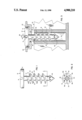
FIG. 1 is a side elevation of a screw fastener constructed in accordance with the invention;
FIG. 2 is a sectional view of the fastener of FIG. 1 taken along the line 2--2; and
FIG. 3 is a partial sectional view of an enclosure and panel incorporating the fastening system of the invention.
Referring to FIGS. 1 and 2, a threaded fastener 10 includes a circular head 12, having a screwdriver slot 14 therein, and a cylindrical shank 16. A spiral thread 18 is segmented into a plurality of thread segments 18a, 18b, 18c and 18d to form separated longitudinal slots 20, 22, 24 and 26 (best seen in FIG. 2). The end of shank 16 terminates in a generally cone shaped entry guide 30. Fastener 10 is preferably molded of plastic material with the slots 20-26 and thread segments 18a-18d being formed during the molding process. The thread preferably includes a taper on its lower side, such as indicated by reference numeral 28, to facilitate insertion of threaded fastener 10 into a receptacle. The segmented construction of the thread imparts a significant degree of flexibility to the threaded segments. It should be apparent to those skilled in the art that the number of slots and their size may be altered for different design applications, the criteria being that the fastener must be secured by the restoring force exerted by the deflected thread segments against the inner surface of the tubular receptacle, and that the thread segments must be strong enough to enable removal of the fastener by engaging a threaded portion in the receptacle entry.
In FIG. 3, a partially shown enclosure 32 has a tubular receptacle 34 formed therein that includes an inner surface 36. The entry of receptacle 34 has a thread 38 of the same pitch as thread 18 on fastener 10 formed therein. A partially shown closing panel 40 has a recess 42 with an aperture 44 at its bottom that the threaded shank of fastener 10 passes through. The fastener head 12 nests within recess 42 when the fastener is installed to secure panel 40 to enclosure 32. It will be apparent that fastener 10 may conveniently be captivated in recess 42 by making aperture 44 slightly smaller in diameter than the diameter of thread 18 and forcing fastener 10 through aperture 44 into position. In this connection, it should be noted that thread segments 18a-18d need not be pie-shaped but may have a generally cloverleaf shape, for example. The term thread diameter should therefore be understood to also mean the greatest distance or widest expanse across the thread segments.
As illustrated at 52 and 54, thread 18 is distorted when pushed into engagement with tubular receptacle 34 and the restoring force exerted by the thread segments against interior surface 36 of receptacle 34 secures fastener 10. A screwdriver blade 50 in slot 14 in head 12, when rotated in a counterclockwise direction as indicated by the arrow, turns threaded fastener 10 causing the segments of thread 18 to engage inner thread 38, formed in the entry of receptacle 34, to thereby permit fastener 10 to be unscrewed. The illustration in FIG. 3 has been idealized to assist in the explanation of the invention.
While the fastener of the fastening system of the invention may be fabricated from any suitable material, plastic is preferred because of its strength, low cost and ability to withstand distortion. Material such as polypropylene, polyethylene and nylon are quite suitable. The receptacle can be made of any type of polymeric material.
Those skilled in the art will readily envision many other arrangements for affixing a member, such as panel 40, to an enclosure, such as enclosure 32, with the fastening system of the invention. The described embodiment is merely illustrative of the preferred form of the invention. As mentioned, a greater or lesser number of thread segments and slots may be utilized and alignment of the thread segments is not required. Similarly, a full inner thead 38 is not a requirement, it being only necessary to have some thread engaging surface, preferably located at the entry of the receptacle. Thus it should be clear that numerous changes in the described embodiment of the invention will be apparent to those skilled in the art without departing from its true spirit and scope. The invention is to be limited only as defined in the claims.
Claims (7)
1. A fastening system comprising:
a fastener means having a drive head and a threaded shank means, said threaded shank means including a plurality of resilient thread segments;
receptacle means defining an orifice that is smaller than the greatest distance across said thread segments such that said resilient thread segments are deformed when said fastening means is inserted in said receptacle means; and
thread engaging means in said receptacle means for engaging said thread segments and imparting a removal force to said fastener means upon rotation thereof.
2. The system of claim 1 wherein said thread engaging means comprises a threaded surface adjacent to the entrance of said receptacle means.
3. The system of claim 2 wherein said threaded shank means includes a generally cylindrical shank and wherein said receptacle means is generally cylindrical, the diameter of said receptacle means being greater than the diameter of said shank.
4. The system of claim 3 wherein said thread segments are tapered at their undersides to facilitate entry into said receptacle means.
5. The system of claim 4, further including a guide tip on said shank for aiding entry of said fastener means into said receptacle means.
6. The system of claim 5 wherein said drive head includes a screwdriver slot and wherein said resilient thread segments comprise groups of four segments.
7. A push in-screw out fastening system comprising:
a molded, threaded fastener including a slotted head and a threaded cylindrical shank having a plurality of resilient thread segments;
a tubular receptacle, having a diameter smaller than the widest expanse of said resilient thread segments, but larger than the diameter of said cylindrical shank, and a thread engaging section adjacent the entry of said tubular receptacle for imparting a removal force to said threaded fastener upon rotation of said slotted head.
Priority Applications (1)
| Application Number | Priority Date | Filing Date | Title |
|---|---|---|---|
| US07/384,607 US4900210A (en) | 1989-07-19 | 1989-07-19 | Push in-screw out fastening system |
Applications Claiming Priority (1)
| Application Number | Priority Date | Filing Date | Title |
|---|---|---|---|
| US07/384,607 US4900210A (en) | 1989-07-19 | 1989-07-19 | Push in-screw out fastening system |
Publications (1)
| Publication Number | Publication Date |
|---|---|
| US4900210A true US4900210A (en) | 1990-02-13 |
Family
ID=23517993
Family Applications (1)
| Application Number | Title | Priority Date | Filing Date |
|---|---|---|---|
| US07/384,607 Expired - Fee Related US4900210A (en) | 1989-07-19 | 1989-07-19 | Push in-screw out fastening system |
Country Status (1)
| Country | Link |
|---|---|
| US (1) | US4900210A (en) |
Cited By (31)
| Publication number | Priority date | Publication date | Assignee | Title |
|---|---|---|---|---|
| US4993575A (en) * | 1989-06-13 | 1991-02-19 | Telemecanique | Quick closure box |
| US5195859A (en) * | 1990-08-20 | 1993-03-23 | The Glasscrew Company | Fastener for joining a plurality of layers |
| US5468108A (en) * | 1994-09-12 | 1995-11-21 | Illinois Tool Works Inc. | Spiral flex tree fastener |
| US5542799A (en) * | 1994-12-02 | 1996-08-06 | Agora Enterprises, L.L.P. | Machine screw |
| WO1997015761A1 (en) * | 1995-10-23 | 1997-05-01 | Lars Eriksson | Improvements in or relating to a fastening element |
| US5653410A (en) * | 1995-08-21 | 1997-08-05 | Chrysler Corporation | Non-pivoting wire harness clip with offset shank |
| US5672038A (en) * | 1995-11-20 | 1997-09-30 | Ford Global Technologies, Inc. | Fastener |
| EP0848171A1 (en) * | 1996-12-12 | 1998-06-17 | TRW United-Carr GmbH & Co. KG | Plastic retaining element. |
| US5868537A (en) * | 1998-05-29 | 1999-02-09 | Illinois Tool Works Inc. | Sponge head retainer pin |
| US6077012A (en) * | 1998-12-01 | 2000-06-20 | Huck International Inc. | Self-retaining fastener |
| US6514023B2 (en) | 2001-05-24 | 2003-02-04 | Illinois Tool Works Inc. | Removable and reusable fastener |
| US6536718B2 (en) * | 2001-01-11 | 2003-03-25 | Aparellaje Electrico, S.L. | Pressure plug for supporting electric cables |
| US20030082026A1 (en) * | 2001-10-05 | 2003-05-01 | Brletich Michael F. | Push-in removable fastener |
| US20050025564A1 (en) * | 1998-07-30 | 2005-02-03 | Richard Humpert | Method of attaching a functional element; die; functional element; component assembly |
| NL1028757C2 (en) * | 2005-04-13 | 2006-10-16 | Pipelife Nederland Bv | Screw-on dowel. |
| FR2902902A1 (en) * | 2006-06-23 | 2007-12-28 | Peugeot Citroen Automobiles Sa | Sports motor vehicle e.g. sports car, pedal, has screwdriver unscrewing circular cylindrical fixation bodies, and threads forming helicoidal coil on surface of cylindrical body with diameter higher than diameter of hole of pad |
| NL1035894C2 (en) * | 2008-09-04 | 2009-05-20 | Klaas Sake Tolsma | Spring clips for mounting switch box, get attached to switch box when pressed |
| US20090178249A1 (en) * | 2008-01-15 | 2009-07-16 | Shaun Jalbert | Auger clip assembly |
| US20090263210A1 (en) * | 2008-04-18 | 2009-10-22 | Twa Automotive Electronics & Components Gmbh | Connecting assembly for fastening an add-on element on a carrier element |
| WO2012166532A1 (en) * | 2011-06-02 | 2012-12-06 | A. Raymond Et Cie | Spiral fastener and method of manufacture |
| EP2714375A1 (en) * | 2011-06-02 | 2014-04-09 | A. Raymond et Cie | Fasteners manufactured by three-dimensional printing |
| US8916085B2 (en) | 2011-06-02 | 2014-12-23 | A. Raymond Et Cie | Process of making a component with a passageway |
| US20160177992A1 (en) * | 2014-12-19 | 2016-06-23 | Lung-Chang Lin | Connector for Steel Reinforcing Bars |
| US20160223100A1 (en) * | 2004-04-30 | 2016-08-04 | Hellermann Tyton Corporation | Fir tree mount |
| CN107269647A (en) * | 2016-04-08 | 2017-10-20 | 赫勒曼泰顿股份有限公司 | Fir tree mounting seat |
| CN108150502A (en) * | 2018-02-21 | 2018-06-12 | 谢红太 | A kind of construction of railways scene Special precision instrument top lifting device |
| US10582925B2 (en) | 2017-02-06 | 2020-03-10 | Medos International Sarl | Devices, systems, and methods for knotless suture anchors |
| CN111140582A (en) * | 2018-11-02 | 2020-05-12 | 吴易璋 | Push screw |
| US11209037B2 (en) * | 2019-07-03 | 2021-12-28 | David Adams | Screw and anchor assembly |
| US20220074442A1 (en) * | 2020-06-04 | 2022-03-10 | Hando Kim | Compliant self-anchoring screw with auxetic properties |
| US20220265069A1 (en) * | 2021-02-25 | 2022-08-25 | Tracer Imaging Llc | Vertical slot hanger |
Citations (4)
| Publication number | Priority date | Publication date | Assignee | Title |
|---|---|---|---|---|
| GB520169A (en) * | 1938-10-14 | 1940-04-16 | Universal Rubber Paviors Ltd | Improvements in or relating to rubber plugs or stoppers |
| GB1020694A (en) * | 1963-07-25 | 1966-02-23 | Albert Victor Raymond | Improvements in and relating to studs |
| US3244057A (en) * | 1963-10-02 | 1966-04-05 | Robert V Mathison | Drive-type screw fastener |
| US3466966A (en) * | 1967-11-13 | 1969-09-16 | Robin Products Co | Resilient fastening device in threaded bore |
-
1989
- 1989-07-19 US US07/384,607 patent/US4900210A/en not_active Expired - Fee Related
Patent Citations (4)
| Publication number | Priority date | Publication date | Assignee | Title |
|---|---|---|---|---|
| GB520169A (en) * | 1938-10-14 | 1940-04-16 | Universal Rubber Paviors Ltd | Improvements in or relating to rubber plugs or stoppers |
| GB1020694A (en) * | 1963-07-25 | 1966-02-23 | Albert Victor Raymond | Improvements in and relating to studs |
| US3244057A (en) * | 1963-10-02 | 1966-04-05 | Robert V Mathison | Drive-type screw fastener |
| US3466966A (en) * | 1967-11-13 | 1969-09-16 | Robin Products Co | Resilient fastening device in threaded bore |
Cited By (49)
| Publication number | Priority date | Publication date | Assignee | Title |
|---|---|---|---|---|
| US4993575A (en) * | 1989-06-13 | 1991-02-19 | Telemecanique | Quick closure box |
| US5195859A (en) * | 1990-08-20 | 1993-03-23 | The Glasscrew Company | Fastener for joining a plurality of layers |
| US5468108A (en) * | 1994-09-12 | 1995-11-21 | Illinois Tool Works Inc. | Spiral flex tree fastener |
| GB2293203A (en) * | 1994-09-12 | 1996-03-20 | Illinois Tool Works | Push-in fastener |
| CN1058323C (en) * | 1994-09-12 | 2000-11-08 | 伊利诺斯工具制造公司 | Spiral flex tree fastener |
| US5542799A (en) * | 1994-12-02 | 1996-08-06 | Agora Enterprises, L.L.P. | Machine screw |
| US5653410A (en) * | 1995-08-21 | 1997-08-05 | Chrysler Corporation | Non-pivoting wire harness clip with offset shank |
| WO1997015761A1 (en) * | 1995-10-23 | 1997-05-01 | Lars Eriksson | Improvements in or relating to a fastening element |
| US5672038A (en) * | 1995-11-20 | 1997-09-30 | Ford Global Technologies, Inc. | Fastener |
| EP0848171A1 (en) * | 1996-12-12 | 1998-06-17 | TRW United-Carr GmbH & Co. KG | Plastic retaining element. |
| DE19651784C1 (en) * | 1996-12-12 | 1998-08-06 | United Carr Gmbh Trw | Holding element made of plastic |
| US5868537A (en) * | 1998-05-29 | 1999-02-09 | Illinois Tool Works Inc. | Sponge head retainer pin |
| US20050025564A1 (en) * | 1998-07-30 | 2005-02-03 | Richard Humpert | Method of attaching a functional element; die; functional element; component assembly |
| US20050172469A1 (en) * | 1998-07-30 | 2005-08-11 | Profil Verbindungstechnik Gmbh & Co. Kg | Method of attaching a functional element; die; functional element; component assembly |
| US7160072B2 (en) * | 1998-10-16 | 2007-01-09 | Profil Verbindungstechnik Gmbh & Co. Kg | Method of attaching a functional element; die; functional element; component assembly |
| US7322086B2 (en) | 1998-10-16 | 2008-01-29 | Profil Verbindungstechnik Gmbh & Co. Kg | Method of attaching a functional element; die; functional element; component assembly |
| US6077012A (en) * | 1998-12-01 | 2000-06-20 | Huck International Inc. | Self-retaining fastener |
| US6536718B2 (en) * | 2001-01-11 | 2003-03-25 | Aparellaje Electrico, S.L. | Pressure plug for supporting electric cables |
| US6514023B2 (en) | 2001-05-24 | 2003-02-04 | Illinois Tool Works Inc. | Removable and reusable fastener |
| US20030082026A1 (en) * | 2001-10-05 | 2003-05-01 | Brletich Michael F. | Push-in removable fastener |
| US6979163B2 (en) * | 2001-10-05 | 2005-12-27 | Illinois Tool Works Inc. | Push-in removable fastener |
| US20160223100A1 (en) * | 2004-04-30 | 2016-08-04 | Hellermann Tyton Corporation | Fir tree mount |
| NL1028757C2 (en) * | 2005-04-13 | 2006-10-16 | Pipelife Nederland Bv | Screw-on dowel. |
| FR2902902A1 (en) * | 2006-06-23 | 2007-12-28 | Peugeot Citroen Automobiles Sa | Sports motor vehicle e.g. sports car, pedal, has screwdriver unscrewing circular cylindrical fixation bodies, and threads forming helicoidal coil on surface of cylindrical body with diameter higher than diameter of hole of pad |
| US20090178249A1 (en) * | 2008-01-15 | 2009-07-16 | Shaun Jalbert | Auger clip assembly |
| US7748089B2 (en) * | 2008-01-15 | 2010-07-06 | Illinois Tool Works Inc. | Auger clip assembly |
| US20090263210A1 (en) * | 2008-04-18 | 2009-10-22 | Twa Automotive Electronics & Components Gmbh | Connecting assembly for fastening an add-on element on a carrier element |
| NL1035894C2 (en) * | 2008-09-04 | 2009-05-20 | Klaas Sake Tolsma | Spring clips for mounting switch box, get attached to switch box when pressed |
| US10207460B2 (en) | 2011-06-02 | 2019-02-19 | A. Raymond Et Cie | Method of making hinged fasteners by three-dimensional printing |
| WO2012166532A1 (en) * | 2011-06-02 | 2012-12-06 | A. Raymond Et Cie | Spiral fastener and method of manufacture |
| EP2714375A1 (en) * | 2011-06-02 | 2014-04-09 | A. Raymond et Cie | Fasteners manufactured by three-dimensional printing |
| US8883064B2 (en) | 2011-06-02 | 2014-11-11 | A. Raymond & Cie | Method of making printed fastener |
| US8916085B2 (en) | 2011-06-02 | 2014-12-23 | A. Raymond Et Cie | Process of making a component with a passageway |
| US9511544B2 (en) | 2011-06-02 | 2016-12-06 | A. Raymond et Cie | Method of making fasteners by three-dimensional printing |
| US10220575B2 (en) | 2011-06-02 | 2019-03-05 | A. Raymond Et Cie | Method of making nut fasteners |
| US10207461B2 (en) | 2011-06-02 | 2019-02-19 | A. Raymond Et Cie | Method of making winged fasteners by three-dimensional printing |
| US20160177992A1 (en) * | 2014-12-19 | 2016-06-23 | Lung-Chang Lin | Connector for Steel Reinforcing Bars |
| CN107269647A (en) * | 2016-04-08 | 2017-10-20 | 赫勒曼泰顿股份有限公司 | Fir tree mounting seat |
| CN107269647B (en) * | 2016-04-08 | 2021-04-02 | 海尔曼太通股份有限公司 | Fir tree shaped mounting seat |
| US10582925B2 (en) | 2017-02-06 | 2020-03-10 | Medos International Sarl | Devices, systems, and methods for knotless suture anchors |
| US11284882B2 (en) | 2017-02-06 | 2022-03-29 | Medos International Sarl | Devices, systems, and methods for knotless suture anchors |
| CN108150502A (en) * | 2018-02-21 | 2018-06-12 | 谢红太 | A kind of construction of railways scene Special precision instrument top lifting device |
| CN111140582A (en) * | 2018-11-02 | 2020-05-12 | 吴易璋 | Push screw |
| GB2579897A (en) * | 2018-11-02 | 2020-07-08 | Yi Chang Wu | Pressing-type screw |
| US11209037B2 (en) * | 2019-07-03 | 2021-12-28 | David Adams | Screw and anchor assembly |
| US20220074442A1 (en) * | 2020-06-04 | 2022-03-10 | Hando Kim | Compliant self-anchoring screw with auxetic properties |
| US11867216B2 (en) * | 2020-06-04 | 2024-01-09 | Hando Kim | Compliant self-anchoring screw with auxetic properties |
| US20220265069A1 (en) * | 2021-02-25 | 2022-08-25 | Tracer Imaging Llc | Vertical slot hanger |
| US11844448B2 (en) * | 2021-02-25 | 2023-12-19 | Tracer Imaging Llc | Vertical slot hanger |
Similar Documents
| Publication | Publication Date | Title |
|---|---|---|
| US4900210A (en) | Push in-screw out fastening system | |
| US4355198A (en) | Screw retaining and aligning cover plate | |
| US6979163B2 (en) | Push-in removable fastener | |
| US6533515B2 (en) | Fastener having movable drive pin | |
| KR0167835B1 (en) | Spiral flex tree fastener | |
| US4902182A (en) | Push-in fastener | |
| US4371137A (en) | Wire bundle clamp | |
| US4911726A (en) | Fastener/retaining ring assembly | |
| US3093027A (en) | Plastic drive fastener having a radially collapsible shoulder | |
| US5306098A (en) | Plastic drive fastener | |
| US4704929A (en) | Device for setting screw | |
| US3341903A (en) | Plastic fastener | |
| US5842822A (en) | Removable quasi-ratchet fastener | |
| US5173025A (en) | Screw grommet having a secured internal thread member | |
| US4940355A (en) | Quick install and release fastening system | |
| US4214667A (en) | Screw mounting mechanism for electrical outlet box | |
| CA2207134A1 (en) | Separable bottom stop assembly for slide fastener | |
| US3136350A (en) | Plastic screw anchor | |
| US4133245A (en) | Fastening device | |
| US5098239A (en) | Cover cap for a hexagonal recess | |
| US6152667A (en) | Blind aperture fastener | |
| CA2232891C (en) | Stud retention device | |
| EP0886074A1 (en) | Fastening clip | |
| EP0193337A1 (en) | Screw grommet | |
| US5596177A (en) | Bushing for multiple sized and shaped holes in structural members |
Legal Events
| Date | Code | Title | Description |
|---|---|---|---|
| AS | Assignment |
Owner name: SQUARE D COMPANY, PALATINE, ILLINOIS A CORP. OF DE Free format text: ASSIGNMENT OF ASSIGNORS INTEREST.;ASSIGNORS:BUCHANAN, JEFFERY J.;CASSITY, TERRANCE A.;REEL/FRAME:005102/0343 Effective date: 19890710 |
|
| FPAY | Fee payment |
Year of fee payment: 4 |
|
| REMI | Maintenance fee reminder mailed | ||
| LAPS | Lapse for failure to pay maintenance fees | ||
| FP | Expired due to failure to pay maintenance fee |
Effective date: 19980218 |
|
| STCH | Information on status: patent discontinuation |
Free format text: PATENT EXPIRED DUE TO NONPAYMENT OF MAINTENANCE FEES UNDER 37 CFR 1.362 |