US4901202A - Controlled access telecommunications equipment cabinet - Google Patents
Controlled access telecommunications equipment cabinet Download PDFInfo
- Publication number
- US4901202A US4901202A US07/314,268 US31426889A US4901202A US 4901202 A US4901202 A US 4901202A US 31426889 A US31426889 A US 31426889A US 4901202 A US4901202 A US 4901202A
- Authority
- US
- United States
- Prior art keywords
- access
- compartments
- enclosure
- access panel
- cabinet
- Prior art date
- Legal status (The legal status is an assumption and is not a legal conclusion. Google has not performed a legal analysis and makes no representation as to the accuracy of the status listed.)
- Expired - Lifetime
Links
Images

Classifications
-
- H—ELECTRICITY
- H02—GENERATION; CONVERSION OR DISTRIBUTION OF ELECTRIC POWER
- H02B—BOARDS, SUBSTATIONS OR SWITCHING ARRANGEMENTS FOR THE SUPPLY OR DISTRIBUTION OF ELECTRIC POWER
- H02B1/00—Frameworks, boards, panels, desks, casings; Details of substations or switching arrangements
- H02B1/26—Casings; Parts thereof or accessories therefor
- H02B1/30—Cabinet-type casings; Parts thereof or accessories therefor
- H02B1/305—Cable entries
-
- H—ELECTRICITY
- H02—GENERATION; CONVERSION OR DISTRIBUTION OF ELECTRIC POWER
- H02B—BOARDS, SUBSTATIONS OR SWITCHING ARRANGEMENTS FOR THE SUPPLY OR DISTRIBUTION OF ELECTRIC POWER
- H02B1/00—Frameworks, boards, panels, desks, casings; Details of substations or switching arrangements
- H02B1/26—Casings; Parts thereof or accessories therefor
- H02B1/30—Cabinet-type casings; Parts thereof or accessories therefor
-
- H—ELECTRICITY
- H02—GENERATION; CONVERSION OR DISTRIBUTION OF ELECTRIC POWER
- H02G—INSTALLATION OF ELECTRIC CABLES OR LINES, OR OF COMBINED OPTICAL AND ELECTRIC CABLES OR LINES
- H02G15/00—Cable fittings
- H02G15/02—Cable terminations
- H02G15/06—Cable terminating boxes, frames or other structures
- H02G15/076—Cable terminating boxes, frames or other structures for multi-conductor cables
-
- H—ELECTRICITY
- H02—GENERATION; CONVERSION OR DISTRIBUTION OF ELECTRIC POWER
- H02G—INSTALLATION OF ELECTRIC CABLES OR LINES, OR OF COMBINED OPTICAL AND ELECTRIC CABLES OR LINES
- H02G9/00—Installations of electric cables or lines in or on the ground or water
- H02G9/10—Installations of electric cables or lines in or on the ground or water in cable chambers, e.g. in manhole or in handhole
Definitions
- This invention relates to a cabinet for housing electronic equipment, terminal blocks and other equipment and more particularly to such a cabinet which partitions equipment in a manner such that access thereto is controlled as well as providing various other features.
- Cabinets or closures are used in the telecommunications industry to provide housings for a variety of equipment.
- the equipment housed therein may be a combination of electronic equipment such as a digital carrier system, a cross-connect field, power outlet(s), power equipment for the electronic equipment, cable splicing equipment, etc.
- such cabinets provide access to the equipment housed therein by either front and/or rear doors. All of the functional activity associated with equipment can only take place in the main cabinet opening which is accessible through the front and/or rear doors.
- such cabinets have a support structure or base.
- the base may be either a solid, single structure or two pedestal/column type structures.
- the cabinet, including the support structure is lowered over the telephone cable associated with the cabinet.
- the cbale is then routed through the support structure.
- the cable may be pulled through the support structure.
- this routing or pulling of the cable through the support structure requires the craftsperson to perform that function in a congested or restricted area.
- the area in which the cable is normally worked on or secured is located in the same general area as is the equipment housed in the cabinet. Additionally, access to the support structure is through the front doors.
- the craftsperson working with the cable has both a limited area in which to perform the cable routing as well as unnecessary access to the entire contents of the cabinet.
- One example of a prior art cabinet is the MODCAB closure manufactured by assignee's Reliable Electronic/Utility Products operating unit. That cabinet has a single, solid structure for the base.
- Another example of a prior art cabinet is that manufactured by AT&T Technologies (formerly Western Electric Company). That cabinet uses the two pedestal/column type structures for a support base.
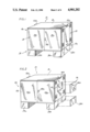
- FIG. 1 front and right side perspective view of an equipment cabinet in accordance with the invention
- FIG. 2 is a rear and left side view of the equipment cabinet of FIG. 1;
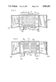
- FIG. 3 is a front elevation of the equipment cabinet of FIGS. 1 and 2, with front access panels open to reveal the contents of a compartment therebehind;
- FIG. 4 is a rear elevation of the cabinet of FIGS. 1 through 3, with rear access panels or doors opened to reveal contents of an equipment compartment therebehind;
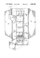
- FIG. 5 is a side elevation of the right-hand side of the equipment cabinet of FIGS. 1 through 4, illustrating access panels removed therefrom to permit access to further equipment compartments therebehind;
- FIG. 6 is an enlarged top perspective view of the mounting plates and split cable sleeve of FIG. 5;
- FIG. 7 is a perspective view similar to FIG. 6 illustrating a first one of the mounting plates removed.
- FIG. 8 is a perspective view similar to FIG. 7 and showing a second of the mounting plates removed.
- FIG. 1 there is front, top and right side view of a cabinet 10 constructed in accordance with the present invention.
- the term "housing” (20) will be used hereinafter to refer to that part of cabinet 10 in which various equipment such as the cross-connect terminals and/or electronic equipment, etc. are mounted.
- the term “base assembly” (14) willbe used hereinafter to refer to that part of cabinet 10 on which the housing 20 is mounted, the housing 20 and base assembly 14 making up the cabinet 10.
- cabinet 10 has a housing 20 which has a front wall or panel 12 which in turn includes a pair of front access panels or doors 12a, 12b. These doors are hingedly mounted to allow access to the interiorof the housing.
- a locking mechanism 12c is included on door 12a. As is wellknown in the art a special mating unlocking tool (not shown) is required tounlock the doors.
- the locking mechanism 12c may also include means (not shown) for further securing the mechanism with a padlock.
- Housing 20 also includes a top wall or panel 16, a right side wall or panel18 having an access panel or door 18a, with locking means 18c and lifting rails 22a, 22b mounted on the right and left sides, respectively, of the housing.
- Base assembly 14 is preferably a split base arrangement made up of two similar upstanding structures 14a and 14b. Structure 14a is adjacent to the right side of the housing whereas structure 14b is adjacent to the left side of the housing. Structure 14a includes therein aremovable access panel 14c. As will be described in more detail hereinafter, the means for routing of cables located on the right side 18 of cabinet 10 and access is provided thereto by removing panel 14c and opening door 18a.
- housing 20 also has a rear wall or panel 24 which may also include a pair of rear access panels or doors 24a, 24b. These doors are hingedly mounted to allow access to the interior of the housing.
- a locking mechanism 24c which is essentially identical to locking mechanism 12c is included on door 24a.
- Housing 20 also includes left side 26 having a compartment 40 defined by interior partitions 40a, 40b, etc. accessible by way of an access panel ordoor 26a.
- Access panel 26a may also include therein a window 26b and is provided with locking means 26c.
- Pedestal structure 14b includes therein afurther compartment 15 accessible by way of a removable access panel 14d.
- Means (not shown) for routing and connecting an A.C. powerline for providing A.C. power is located in compartments 15, 40 on the left side 26of cabinet 10 and access is provided thereto by removing panel 14d and opening door 26a.
- Cabinet 10 may include a compartment 25 defined by interior partitions 25a,25b, 25c, etc. (see FIG. 3) for cross connect terminals of a type well known in the art. These terminals allow for a cross connection between thecentral office cable pairs and the subscriber cable pairs.
- FIG. 3 One such exampleof a representative configuration for the cross connect terminals mounted in compartment 25 of the cabinet 10 is shown in FIG. 3. Access thereto is obtained by opening the front doors 12a, 12b.
- the cross connect terminals include a feeder field 28 which is made up of terminal blocks arranged in columns and blocks 28a and 28b.
- the central office cable pairs are connected to the rear of the blocks 28a and 28b.
- the cross connect terminals also include a distribution field which is made up of terminal blocks arranged in two distinct groups 30a and 30b.
- the cross connect terminals also include channels 32a, 32b and 32c each ofwhich contain rings 32d. The channels and the rings ensure an orderly routing for the jumper wires used to interconnect appropriate pairs of terminals of the feeder field to appropriate pairs of terminals of the distribution field.
- the blocks of column 28a and of group 30a are mounted on a panel 34a which may be hinged as diagrammatically indicated at 35a onits right side.
- the blocks of column 28b and group 30b are mounted on a panel 34b which may be hinged as diagrammatically indicated at 35b on its left side.
- Cabinet 10 may also include a further compartment 35 defined by interior partitions 35a, 35b, 35c, etc. (See FIG. 4) for certain electronic equipment, power supplies therefor, power outlets, and other associated equipment.
- One representative configuration for the equipment mounted in compartment 35 of cabinet 10 is shown somewhat diagrammatically in FIG. 4.Access thereto is obtained by opening the rear doors 24a, 24b.
- the equipment may include protector banks 36a for surge arrestor or line protector elements, rack mounted electronic circuit cards 36b, various pieces of power equipment 36c, A.C. outlets 36d, and a load center36e containing circuit breakers.
- compartment 45 defined by interior partitions 45a, 45b, 45c, etc. is provided on the right side 18 of the housing 20.
- This compartment 45 is accessible by way of removable access panel or door 18a.
- a further aligned compartment 14e is accessible by way of removable access panel or door 14c.
- These compartments 14e, 45 are provided for the routing and splicing of cables from outside the enclosureto service the telephone equipment therewithin.
- the base or support member 14a is aligned with and mounted over an area at which underground cables emerge for routing through compartments 14e and 45.
- intermediate mounting plates 51, 52 mount a plurality of split cable sleeves 50, which in turn mount respective cable guiding nozzles 48 to facilitate the entry and routing of cables through compartment 14e and into conveniently accessible compartment 45 for completing routing and/or splicing operations.
- These mounting plates along with the split cable sleeves are removable (slide forward -- see FIGS. 6, 7 and 8), providing total access to the side of the housing. This removability allows the cabinet to be passed over (sliding over) cable in lieu of lifting over cable, providing an additional feature of the invention, namely, permitting rehabilitation or replacement of old cabinets without cutting the cable or cables.
- compartment 45 is unencumbered by any equipment unrelated to the splicing and routing of thecables, so as to permit free and unencumbered access to the cables within the compartment for these purposes.
- each of the above described compartments defined in the housing or cabinet 20 receives or mounts a different portion of the equipment for serving a different function or purpose in the telecommunications equipment cabinet. That is, the equipment related to the cross connect terminals and related wiring is allconfined to compartment 25, and is inaccessible from any other compartment. Similarly, the electronic equipment and power supplies therefor, as well asthe protector banks and load center are all confined to compartment 35 and are inaccessible from any other compartment. In similar fashion, the routing and splicing of cables is performed exclusively in compartments 14e and 45, while the A.C. power routing and connections are available only in compartment 40.
- the locking means forthe access doors or panels each of the compartments requires a separate anddifferent mating unlocking device or means. That is, one type of unlocking tool, key or the like is required for opening locking means 12c, while an entirely different type is required for locking means 24c, and yet other types of tool and/or keys are required for opening the locking means 26c and 18c, respectively.
- access to each of the different compartments of the equipment cabinet may be limited to the craftspersons having the necessary skills to peform the function or operations appropriate to the equipment in each compartment, by limiting access to each mating unlocking means or key onlyto the authorized or properly skilled craftspersons.
- the cabinet is mounted by means of the split base 14 to a concrete pad through which suitable underground A.C. powerlines and the necessary underground cables have already been fed so as to be in alignment respectively with structures 14a and 14b, to permit the necessary routing and internal connections thereof as mentioned above.
- the base assembly 14 as a split base or dual pedestal type of base in the form illustrated and described permits relatively easy separation of the respective compartments 14e and 15 therein for the separate entrance and initial routing of respective cables and A.C. powerlines and alignment thereof with respect to the respective compartments 40, 45 immediately thereabove.
- a novel and improved controlledaccess telecommunications equipment cabinet in which a plurality of separate and independent compartments are provided for each of a number ofgroups of interrelated telecommunications equipment required for the telecommunications installation.
- the equipment may be arranged in these separate and independent compartments in accordance withthe skill level of craftsmen required for installation, maintenance and repair of each type of equipment. Accordingly, it is assured that only craftspersons of the requisite skill level will have access to the equipment in a given compartment, which conversely houses only equipment associated with that skill.
- Such access is limited by means of providing locking access panels or doors for each compartment, each of which lockingpanels or doors requires some different type of unlocking mechanism, key orthe like for access. Accordingly, control of the distribution of the unlocking means or keys will assure that only the craftsperson of the requisite skill will possess an unlocking means or key for, and hence, access to, a given compartment in the equipment cabinet.
Abstract
Description
Claims (3)
Priority Applications (1)
| Application Number | Priority Date | Filing Date | Title |
|---|---|---|---|
| US07/314,268 US4901202A (en) | 1987-04-06 | 1989-02-24 | Controlled access telecommunications equipment cabinet |
Applications Claiming Priority (2)
| Application Number | Priority Date | Filing Date | Title |
|---|---|---|---|
| US3509487A | 1987-04-06 | 1987-04-06 | |
| US07/314,268 US4901202A (en) | 1987-04-06 | 1989-02-24 | Controlled access telecommunications equipment cabinet |
Related Parent Applications (1)
| Application Number | Title | Priority Date | Filing Date |
|---|---|---|---|
| US3509487A Continuation | 1987-04-06 | 1987-04-06 |
Publications (1)
| Publication Number | Publication Date |
|---|---|
| US4901202A true US4901202A (en) | 1990-02-13 |
Family
ID=26711749
Family Applications (1)
| Application Number | Title | Priority Date | Filing Date |
|---|---|---|---|
| US07/314,268 Expired - Lifetime US4901202A (en) | 1987-04-06 | 1989-02-24 | Controlled access telecommunications equipment cabinet |
Country Status (1)
| Country | Link |
|---|---|
| US (1) | US4901202A (en) |
Cited By (21)
| Publication number | Priority date | Publication date | Assignee | Title |
|---|---|---|---|---|
| US5208737A (en) * | 1991-08-14 | 1993-05-04 | Minnesota Mining And Manufacturing Company | Cross connect cabinet for telecommunications equipment |
| US5315794A (en) * | 1992-10-30 | 1994-05-31 | Professional Systems, Inc. | Enclosure for telecommunications equipment |
| US5398161A (en) * | 1993-07-23 | 1995-03-14 | Excel, Inc. | Telecommunications switch chassis having housing with front and rear compartments divided by interior partition and removable cover over rear compartment |
| GB2293493A (en) * | 1994-09-23 | 1996-03-27 | Contactum Ltd | Enclosure for electrical components |
| US5781410A (en) * | 1996-01-17 | 1998-07-14 | Nec America, Inc. | Densely packed telecommunications equipment enclosure |
| US6032086A (en) * | 1994-03-08 | 2000-02-29 | Fanuc Ltd. | Control system for industrial robots |
| US6185098B1 (en) * | 2000-01-31 | 2001-02-06 | Chatsworth Products, Inc. | Co-location server cabinet |
| US6229707B1 (en) * | 1999-07-14 | 2001-05-08 | Hendry Mechanical Works | Calamity-proof electrical equipment cabinet door systems |
| US6259605B1 (en) | 1998-12-22 | 2001-07-10 | Dell Usa, L.P. | Front accessible computer and chassis |
| US6313983B1 (en) * | 1999-01-08 | 2001-11-06 | Hon Hai Precision Ind. Co., Ltd. | Computer enclosure |
| US6438226B1 (en) * | 1997-10-06 | 2002-08-20 | Ccs Holdings, Inc. | XDSL splitter assembly for main distribution frame |
| US20040218368A1 (en) * | 2003-04-30 | 2004-11-04 | Hewlett-Packard Development Company, L.P. | Electronic component securement system |
| WO2005015691A1 (en) * | 2003-08-11 | 2005-02-17 | Siemens Aktiengesellschaft | Cable support device for switchgear |
| US20050189132A1 (en) * | 2004-03-01 | 2005-09-01 | Harry Stoller | Cabinet with cross-connect that provides access to rear side of electronic equipment |
| US20050275319A1 (en) * | 2004-06-10 | 2005-12-15 | Charles Industries, Ltd. | Enclosure for telecommunications equipment |
| US6980725B1 (en) | 2002-04-30 | 2005-12-27 | Calix Networks, Inc. | Space reuse during technology upgrade in a protection area of an outdoor enclosure |
| US7351909B1 (en) | 2004-06-10 | 2008-04-01 | Charles Industries, Ltd. | Multilayered housing for electronics enclosures |
| USD684128S1 (en) | 2012-02-10 | 2013-06-11 | Chatsworth Products, Inc. | Containment aisle door |
| US9560777B2 (en) | 2010-11-08 | 2017-01-31 | Chatsworth Products, Inc. | Door closer mechanism for hot/cold aisle air containment room |
| US11246231B2 (en) | 2012-02-10 | 2022-02-08 | Chatsworth Products, Inc. | Door closer mechanism for hot/cold aisle air containment room |
| US11375630B1 (en) * | 2021-03-22 | 2022-06-28 | Liang Light Chen | Power distributor protection |
Citations (11)
| Publication number | Priority date | Publication date | Assignee | Title |
|---|---|---|---|---|
| US2041112A (en) * | 1934-03-03 | 1936-05-19 | Fred J Bucher | Cabinet panel board unit |
| US2077160A (en) * | 1934-07-14 | 1937-04-13 | Bell Telephone Labor Inc | Radio transmitter |
| GB563197A (en) * | 1943-01-28 | 1944-08-02 | Standard Telephones Cables Ltd | Improved chassis construction for mounting radio and like component parts |
| US2542853A (en) * | 1947-05-02 | 1951-02-20 | Westinghouse Electric Corp | Switchboard |
| US3001102A (en) * | 1958-11-12 | 1961-09-19 | Sperry Rand Corp Ford Instr Co | Integrated plug-in unit |
| CA639104A (en) * | 1962-03-27 | L. Defandorf John | Control apparatus | |
| US3188524A (en) * | 1962-09-20 | 1965-06-08 | Lockheed Aircraft Corp | High density circuit card packaging |
| US3502237A (en) * | 1968-03-25 | 1970-03-24 | Donald Verhein | Base for a collapsible container |
| US3589547A (en) * | 1969-05-21 | 1971-06-29 | Irvin Industries Inc | Container construction |
| US4307436A (en) * | 1979-10-04 | 1981-12-22 | Daniel Woodhead, Inc. | Power distribution center |
| US4369484A (en) * | 1981-03-23 | 1983-01-18 | Gte Products Corporation | Multiple meter switchboard |
-
1989
- 1989-02-24 US US07/314,268 patent/US4901202A/en not_active Expired - Lifetime
Patent Citations (11)
| Publication number | Priority date | Publication date | Assignee | Title |
|---|---|---|---|---|
| CA639104A (en) * | 1962-03-27 | L. Defandorf John | Control apparatus | |
| US2041112A (en) * | 1934-03-03 | 1936-05-19 | Fred J Bucher | Cabinet panel board unit |
| US2077160A (en) * | 1934-07-14 | 1937-04-13 | Bell Telephone Labor Inc | Radio transmitter |
| GB563197A (en) * | 1943-01-28 | 1944-08-02 | Standard Telephones Cables Ltd | Improved chassis construction for mounting radio and like component parts |
| US2542853A (en) * | 1947-05-02 | 1951-02-20 | Westinghouse Electric Corp | Switchboard |
| US3001102A (en) * | 1958-11-12 | 1961-09-19 | Sperry Rand Corp Ford Instr Co | Integrated plug-in unit |
| US3188524A (en) * | 1962-09-20 | 1965-06-08 | Lockheed Aircraft Corp | High density circuit card packaging |
| US3502237A (en) * | 1968-03-25 | 1970-03-24 | Donald Verhein | Base for a collapsible container |
| US3589547A (en) * | 1969-05-21 | 1971-06-29 | Irvin Industries Inc | Container construction |
| US4307436A (en) * | 1979-10-04 | 1981-12-22 | Daniel Woodhead, Inc. | Power distribution center |
| US4369484A (en) * | 1981-03-23 | 1983-01-18 | Gte Products Corporation | Multiple meter switchboard |
Cited By (26)
| Publication number | Priority date | Publication date | Assignee | Title |
|---|---|---|---|---|
| US5208737A (en) * | 1991-08-14 | 1993-05-04 | Minnesota Mining And Manufacturing Company | Cross connect cabinet for telecommunications equipment |
| US5315794A (en) * | 1992-10-30 | 1994-05-31 | Professional Systems, Inc. | Enclosure for telecommunications equipment |
| US5398161A (en) * | 1993-07-23 | 1995-03-14 | Excel, Inc. | Telecommunications switch chassis having housing with front and rear compartments divided by interior partition and removable cover over rear compartment |
| US6032086A (en) * | 1994-03-08 | 2000-02-29 | Fanuc Ltd. | Control system for industrial robots |
| GB2293493A (en) * | 1994-09-23 | 1996-03-27 | Contactum Ltd | Enclosure for electrical components |
| GB2293493B (en) * | 1994-09-23 | 1998-10-07 | Contactum Ltd | Consumer unit |
| US5781410A (en) * | 1996-01-17 | 1998-07-14 | Nec America, Inc. | Densely packed telecommunications equipment enclosure |
| US6438226B1 (en) * | 1997-10-06 | 2002-08-20 | Ccs Holdings, Inc. | XDSL splitter assembly for main distribution frame |
| US6259605B1 (en) | 1998-12-22 | 2001-07-10 | Dell Usa, L.P. | Front accessible computer and chassis |
| US6313983B1 (en) * | 1999-01-08 | 2001-11-06 | Hon Hai Precision Ind. Co., Ltd. | Computer enclosure |
| US6229707B1 (en) * | 1999-07-14 | 2001-05-08 | Hendry Mechanical Works | Calamity-proof electrical equipment cabinet door systems |
| US6185098B1 (en) * | 2000-01-31 | 2001-02-06 | Chatsworth Products, Inc. | Co-location server cabinet |
| US6980725B1 (en) | 2002-04-30 | 2005-12-27 | Calix Networks, Inc. | Space reuse during technology upgrade in a protection area of an outdoor enclosure |
| US6930886B2 (en) | 2003-04-30 | 2005-08-16 | Hewlett-Packard Development, L.P. | Electronic component securement system |
| US20040218368A1 (en) * | 2003-04-30 | 2004-11-04 | Hewlett-Packard Development Company, L.P. | Electronic component securement system |
| WO2005015691A1 (en) * | 2003-08-11 | 2005-02-17 | Siemens Aktiengesellschaft | Cable support device for switchgear |
| CN100474700C (en) * | 2003-08-11 | 2009-04-01 | 西门子公司 | Cable support device for switchgear |
| US20050189132A1 (en) * | 2004-03-01 | 2005-09-01 | Harry Stoller | Cabinet with cross-connect that provides access to rear side of electronic equipment |
| US6946600B1 (en) | 2004-03-01 | 2005-09-20 | Commscope Solutions Properties, Llc. | Cabinet with cross-connect that provides access to rear side of electronic equipment |
| US7351909B1 (en) | 2004-06-10 | 2008-04-01 | Charles Industries, Ltd. | Multilayered housing for electronics enclosures |
| US20050275319A1 (en) * | 2004-06-10 | 2005-12-15 | Charles Industries, Ltd. | Enclosure for telecommunications equipment |
| US9560777B2 (en) | 2010-11-08 | 2017-01-31 | Chatsworth Products, Inc. | Door closer mechanism for hot/cold aisle air containment room |
| US10362695B2 (en) | 2010-11-08 | 2019-07-23 | Chatsworth Products, Inc. | Door closer mechanism for hot/cold aisle air containment room |
| USD684128S1 (en) | 2012-02-10 | 2013-06-11 | Chatsworth Products, Inc. | Containment aisle door |
| US11246231B2 (en) | 2012-02-10 | 2022-02-08 | Chatsworth Products, Inc. | Door closer mechanism for hot/cold aisle air containment room |
| US11375630B1 (en) * | 2021-03-22 | 2022-06-28 | Liang Light Chen | Power distributor protection |
Similar Documents
| Publication | Publication Date | Title |
|---|---|---|
| US4901202A (en) | Controlled access telecommunications equipment cabinet | |
| US5001602A (en) | Network interface cabinet for large pair count telephone terminations | |
| US5574251A (en) | Electrical and electronic cabinet systems | |
| US4850014A (en) | Multiple dwelling interface box | |
| US4160880A (en) | Modular termination system for communication lines | |
| US6127627A (en) | Optimized wiring housing | |
| US5363440A (en) | Multilayered type network interface unit | |
| CA2756296C (en) | Fiber splice enclosure | |
| US2480568A (en) | Electrical power distribution and control apparatus | |
| EP0849850B1 (en) | Outdoor cabinet for telecommunication devices and method for support of outdoor cabinets | |
| US4945560A (en) | Telephone network interface apparatus | |
| US5773763A (en) | Mounting device for communication RJ elements (patch panel) which has a rear cable guide strip and a front cable guide ring | |
| US3495135A (en) | Electrical control center structure having symmetrical parts | |
| EP0577433B1 (en) | Racks for electronic equipment | |
| US4700384A (en) | Indoor telephone line demarcation box having several compartments | |
| US5803292A (en) | Uniform building entrance protector housing construction with expandable splice chamber | |
| US5175673A (en) | Distributor for use in communication systems | |
| US3168683A (en) | Control unit structure | |
| US5978472A (en) | Network interface device for a building entrance terminal | |
| AU5163198A (en) | Modular furniture interconnection panel | |
| DE19740246C1 (en) | Housing for connecting power cables and light conductors | |
| US4835659A (en) | Telephone drop box with permanently wired feeder cable | |
| CA2935842C (en) | Doorless modular panelboard | |
| US2773940A (en) | Telecommunication station equipment | |
| US6845206B2 (en) | Interbay housing assembly for fiber optic management systems |
Legal Events
| Date | Code | Title | Description |
|---|---|---|---|
| STCF | Information on status: patent grant |
Free format text: PATENTED CASE |
|
| REMI | Maintenance fee reminder mailed | ||
| FEPP | Fee payment procedure |
Free format text: PAYOR NUMBER ASSIGNED (ORIGINAL EVENT CODE: ASPN); ENTITY STATUS OF PATENT OWNER: LARGE ENTITY |
|
| FPAY | Fee payment |
Year of fee payment: 4 |
|
| SULP | Surcharge for late payment | ||
| FPAY | Fee payment |
Year of fee payment: 8 |
|
| FEPP | Fee payment procedure |
Free format text: PAYOR NUMBER ASSIGNED (ORIGINAL EVENT CODE: ASPN); ENTITY STATUS OF PATENT OWNER: LARGE ENTITY Free format text: PAYER NUMBER DE-ASSIGNED (ORIGINAL EVENT CODE: RMPN); ENTITY STATUS OF PATENT OWNER: LARGE ENTITY |
|
| FEPP | Fee payment procedure |
Free format text: PAYER NUMBER DE-ASSIGNED (ORIGINAL EVENT CODE: RMPN); ENTITY STATUS OF PATENT OWNER: LARGE ENTITY |
|
| AS | Assignment |
Owner name: RELTEC CORPORATION, OHIO Free format text: CHANGE OF NAME;ASSIGNOR:RELIANCE COMM/TEC CORPORATION;REEL/FRAME:011058/0370 Effective date: 19951010 Owner name: RELTEC COMMUNICATIONS, INC., OHIO Free format text: CHANGE OF NAME;ASSIGNOR:RELTEC CORPORATION;REEL/FRAME:011058/0374 Effective date: 19980115 Owner name: MARCONI COMMUNICATIONS, INC., OHIO Free format text: CHANGE OF NAME;ASSIGNOR:RELTEC COMMUNICATIONS, INC.;REEL/FRAME:011089/0100 Effective date: 19990521 |
|
| FPAY | Fee payment |
Year of fee payment: 12 |
|
| AS | Assignment |
Owner name: MARCONI INTELLECTUAL PROPERTY ( RINGFENCE) INC., P Free format text: ASSIGNMENT OF ASSIGNORS INTEREST;ASSIGNOR:MARCONI COMMUNICATIONS, INC.;REEL/FRAME:014675/0855 Effective date: 20031028 |
|
| AS | Assignment |
Owner name: EMERSUB XCII, INC., MISSOURI Free format text: ASSIGNMENT OF ASSIGNORS INTEREST;ASSIGNOR:MARCONI INTELLECTUAL PROPERTY (RINGFENCE) INC.;REEL/FRAME:015394/0222 Effective date: 20040812 |
|
| AS | Assignment |
Owner name: EMERSON NETWORK POWER, ENERGY SYSTEMS, NORTH AMERI Free format text: CHANGE OF NAME;ASSIGNOR:EMERSUB XCII, INC.;REEL/FRAME:015452/0663 Effective date: 20041119 |