US4901894A - Snap on auxiliary bar for hangers - Google Patents

Snap on auxiliary bar for hangers Download PDF

Info

Publication number
US4901894A
US4901894A US07/222,789 US22278988A US4901894A US 4901894 A US4901894 A US 4901894A US 22278988 A US22278988 A US 22278988A US 4901894 A US4901894 A US 4901894A
Authority
US
United States
Prior art keywords
hanger
garment
support bar
clamps
ears
Prior art date
Legal status (The legal status is an assumption and is not a legal conclusion. Google has not performed a legal analysis and makes no representation as to the accuracy of the status listed.)
Expired - Fee Related
Application number
US07/222,789
Inventor
Russell O. Blanchard
Current Assignee (The listed assignees may be inaccurate. Google has not performed a legal analysis and makes no representation or warranty as to the accuracy of the list.)
Ricoh Co Ltd
Batts Inc
Original Assignee
Batts Inc
Priority date (The priority date is an assumption and is not a legal conclusion. Google has not performed a legal analysis and makes no representation as to the accuracy of the date listed.)
Filing date
Publication date
Application filed by Batts Inc filed Critical Batts Inc
Priority to US07/222,789 priority Critical patent/US4901894A/en
Assigned to RICOH COMPANY, LTD., NO. 3-6, 1-CHOME, NAKAMAGOME, OTA-KU, TOKYO, 143 JAPAN, A CORP. OF JAPAN reassignment RICOH COMPANY, LTD., NO. 3-6, 1-CHOME, NAKAMAGOME, OTA-KU, TOKYO, 143 JAPAN, A CORP. OF JAPAN ASSIGNMENT OF ASSIGNORS INTEREST. Assignors: BLANCHARD, RUSSELL O.
Assigned to BATTS, INC., 200 N. FRANKLIN ZEELAND, MI 49464 A CORP. OF MI. reassignment BATTS, INC., 200 N. FRANKLIN ZEELAND, MI 49464 A CORP. OF MI. ASSIGNMENT OF ASSIGNORS INTEREST. Assignors: BLANCHARD, RUSSELL O.
Application granted granted Critical
Publication of US4901894A publication Critical patent/US4901894A/en
Anticipated expiration legal-status Critical
Expired - Fee Related legal-status Critical Current

Links

Images

Classifications

    • AHUMAN NECESSITIES
    • A47FURNITURE; DOMESTIC ARTICLES OR APPLIANCES; COFFEE MILLS; SPICE MILLS; SUCTION CLEANERS IN GENERAL
    • A47GHOUSEHOLD OR TABLE EQUIPMENT
    • A47G25/00Household implements used in connection with wearing apparel; Dress, hat or umbrella holders
    • A47G25/14Clothing hangers, e.g. suit hangers
    • A47G25/28Hangers characterised by their shape

Definitions

  • An auxiliary bar over which articles, such as pants or slacks, can be draped has a detachable connection to a conventional clamping hanger such that it can be added to or removed from the hanger and, when not in use, can be stored until needed. In most cases, the means of anchoring the bar tot he hanger does not require modification of the hanger.
  • An article clamping hanger such as the hanger disclosed in U.S. Pat. No. 3,767,092, entitled GARMENT CLAMPING HANGER WITH SLIDABLE LOCKING CLIP, issued Oct. 23, 1973, to Garrison et al. is a typical hanger to which this invention can be applied.
  • Hangers having this construction are widely used, not only for the display of garments but also for the display of other articles of merchandise such as towels and similar articles.
  • the greatest use of hangers of this type is for the display of clothing such as pants and slacks.
  • the article such as a pair of pants, not hang down for its full length.
  • Such garments must be supported at a high enough level that they will not contact the floor.
  • the garment partially folded so that it can be displayed in association with other garments to provide a coordinated display.
  • this has been accomplished by modifying the clamping hangers by the addition of a bar over which the pants or slacks, for example, can be partially folded or draped.
  • the hangers have been equipped with a wire auxiliary bar which is secured to the rear jaw of the clamps.
  • An alternative to this has been the molding of the clamps with an integral bar which depends from the rear jaw and is positioned below the main body of the hanger. In this latter case, the bar being integral with the hanger, is a permanent part of the hanger and thus is always present, even under circumstances in which its presence is not desired.
  • the wire auxiliary bar In the case of the wire auxiliary bar, this can be made detachable but it requires the hanger to be specially designed to connect the bar. In some cases, a molded plastic auxiliary bar has been substituted for the wire one but, again, it has been necessary to modify the hanger to secure the auxiliary bar. Thus, in all cases, the hanger has to be specially designed and manufactured to adapt it to use of the auxiliary bar. This restricts the use of the auxiliary bar to a very limited number of hangers.
  • This invention provides an auxiliary bar which can be so constructed that it can be detachably secured to a clamping hanger of the presently existing construction which has not been specifically designed to secure it. Furthermore, the invention provides an auxiliary bar so designed that it can be quickly and easily mounted on or removed from the hanger, permitting the hanger to be used in its original condition or modified when needed and returned to its original condition when the auxiliary bar is no longer necessary. Further, the attachment and removal of the auxiliary bar is rapid and uncomplicated and requires no tools and no special instructions.
  • FIG. 1 is a front elevational view of a garment clamping hanger equipped with this invention
  • FIG. 2 is a front elevational view of the auxiliary bar of this invention
  • FIG. 3 is a fragmentary, oblique front view of the auxiliary bar secured to the hanger
  • FIG. 4 is an enlarged, sectional elevational view taken along the plane IV--IV of FIG. 1;
  • FIG. 5 is a fragmentary, oblique front view of a modified construction for the auxiliary bar
  • FIG. 6 is a sectional elevational view taken along the plane VI--VI of FIG. 5;
  • FIG. 6A is an enlarged, fragmentary, exploded view of the auxiliary bar construction illustrated in FIG. 5;
  • FIG. 7 is an enlarged, fragmentary view of a further modification of this invention with the bar anchored to the hanger;
  • FIG. 8 is a fragmentary sectional view taken along the plane VIII--VIII of FIG. 7;
  • FIG. 9 is a fragmentary front view of the anchor end of the auxiliary bar illustrated in FIG. 7;
  • FIG. 10 is an end view of the auxiliary bar illustrated in FIG. 7;
  • FIG. 11 is a fragmentary view illustrating one method of securing to the hanger the auxiliary bar illustrated in FIG. 7;
  • FIG. 12 is a fragmentary front view of a hanger with the auxiliary bar of FIG. 7 secured to it.
  • the numeral 10 identifies a conventional garment clamping hanger having an elongated body 11 supported at its center by a hook 12 and equipped at each end with a garment clamp 13.
  • This hanger is one of the type described in U.S. Pat. No. 3,767,092, issued Oct. 23, 1973 to J. F. Garrison et al.
  • the invention provides an auxiliary bar 20 which is designed to be detachably secured to the hanger body 10.
  • the auxiliary bar has an article supporting, transverse member 21 which terminates in a pair of reversely bent end portions 22 which extend upwardly and inwardly and terminate in an anchor portion 23.
  • the length of the transverse member 21 is greater than that of the hanger 10 to receive a garment supported by the clamps 13.
  • the length of the end portions 22 is such that the anchors 23 for securing the auxiliary bar to the hanger are located just inwardly of the clamps 13.
  • the anchor portions are shaped to form a socket 24 defined by a pair of ears 25 which extend forwardly and terminate in vertically extending fingers which define a front opening which is less than the vertical height of the beam-like body 11.
  • the auxiliary bar is molded of a plastic which has just enough resilience that the gap or opening between the ears 25 can be spread just enough to admit the beam-like body 11 of the hanger into the socket 24 where, because of this resilience, the beam will be clamped by the ears 25.
  • the bar is detachably secured to the hanger and can be removed simply by spreading the ears to release it.
  • the bar is so designed that it seats against the rear face of the hanger with the sockets 24 extending forwardly. As is shown in FIG. 4, the end portions are located in the same vertical plane as the back of the sockets 24. Thus, the auxiliary bar is located in a plane which is rearwardly of the garment receiving chamber 27 of the clamps 13. Thus, the presence of the bar 21 does not interfere with the use and function of the clamps. This is important because the bar is intended to be an auxiliary feature to support an additional object, such as another garment, without in any way interfering with the normal function of the clamps. For example, the bar could be used to drape a pair of slacks with the slacks being gripped by the clamps but the distance the slacks would hang down from the hanger could be reduced because they can be folded to drape over the bar.
  • the bar By making the bar detachable, the bar need be used only when it is required. Further, by making the hanger and the bar as two entirely separate and independent products, the complexity of the necessary molds is substantially reduced. In fact, since the hangers have long since been widely used commercially, only the bar needs to be manufactured to effect this improvement. It will be recognized that the shape of the garment supporting portion of the auxiliary bar can be designed to satisfy any of a number of different requirements because its length and particular cross-sectional shape can vary as needed.
  • the reversely bent end sections can be simple rectangles with their greater dimension extending vertically, as will be observed from inspection of FIG. 3.
  • FIGS. 5, 6 and 6A illustrate a modification of the invention in which the sockets 24 are replaced by a pair of ears 30 and 31 with enlarged heads.
  • the heads have oppositely facing, wedge-shaped portions 32 with an undercut 33 adjacent the forward face of the end portions 22a of the bar. These are designed to be pushed through an appropriate opening 34 in the vertical panel of the beam-like body 11 adjacent each of the clamps 13 (FIG. 6A).
  • the ears are spaced sufficiently that they can be squeezed together just enough to be passed through the opening 34 and once through the opening, due to their resilience, they will separate to seat over the front face of the beam and, thus, lock the auxiliary bar 20a to the hanger body 11.
  • the end of the auxiliary bar 20a is long enough to engage and seat against both the upper and lower flanges of the body (FIG. 6).
  • the base portions of the ears are lengthened to bridge the gap created by the auxiliary bar to seat against the flanges rather than the vertical web. This also has the beneficial effect of making the ears somewhat easier to push together when the auxiliary bar is to be attached or detached from the hanger.
  • FIGS. 7-11 illustrate a different approach to the attachment of an auxiliary bar to a clamping hanger.
  • the hanger has somewhat different garment clamps at each end.
  • the rear leg 40 of a pinch-clip type clamp 41 is integral with the beam or body 11a of the hanger and the front leg 42 is secured to it by a web which functions as a hinge so located that it is substantially spaced from both the upper and lower ends of the legs 40 and 42.
  • the upper portions of the legs form a grip by which the legs can be manipulated to open and close the clamp.
  • the legs are biased to resiliently grip a garment by means of a spring 44 in a manner long known in the garment hanger field.
  • the handle portions of the clamps have central openings 46.
  • the auxiliary bar 20b has a upstanding end portion which terminates in a T-shaped head 48 (FIG. 9).
  • the head provides a pair of laterally extending tabs or ears 49, creating a head wider than the opening 46 through the handle portion of the rear leg. Because of the resiliency of the material from which the end portion 47 of the auxiliary bar is made, these ears can be squeezed together enough to be passed through the opening and then allowed to resume their natural spacing, thus securing the auxiliary bar to the rear leg.
  • An alternative to this in some cases could be turning the head 48 diagonally of the opening enough to pass the tabs through as suggested in FIG. 11.
  • a score line or reduced thickness section 52 may be provided across the end portion just below the tabs to overcome any resilient stiffness which would tend to bias the lower portion of the auxiliary bar to project rearwardly.
  • the rear bar need not necessarily be made of a single integral molded item.
  • the ends can be molded or stamped from plastic material and then inserted in the end of a tubular member with a bonded or an interference fit or both.
  • the tubular member could be plastic or plastic reinforced paper and thereby provide the desired rigidity to support the article and also provide a broad enough supporting surface that whatever is draped over it will not be creased by reason of its weight resting on the auxiliary bar.
  • the auxiliary bar does not materially interfere with the appearance of the hanger from the front because its attachment to the hanger is concealed behind the lower portion of the clamp as is indicated in FIG. 12.
  • the invention provides a relatively inexpensive, easy to use, auxiliary bar which may be added to existing garment hangers of the clamping type. Further, it can be attached or removed easily and quickly and requires no modification of existing hangers of the clamping types. Thus, it provides a relatively inexpensive way of expanding the utility and convenience of existing clamping hangers, when such is desired.

Abstract

For a garment hanger having a rigid, elongated body equipped with garment clamps at each end, an accessory garment support bar is provided having a garment holding portion longer than the spacing between the clamps, which bar is detachably connected to the hanger body inward of the clamps which supports the bar rearwardly of the plane assumed by a garment suspended from the clamps.

Description

SUMMARY OF THE INVENTION
An auxiliary bar over which articles, such as pants or slacks, can be draped has a detachable connection to a conventional clamping hanger such that it can be added to or removed from the hanger and, when not in use, can be stored until needed. In most cases, the means of anchoring the bar tot he hanger does not require modification of the hanger.
BACKGROUND OF THE INVENTION
An article clamping hanger, such as the hanger disclosed in U.S. Pat. No. 3,767,092, entitled GARMENT CLAMPING HANGER WITH SLIDABLE LOCKING CLIP, issued Oct. 23, 1973, to Garrison et al. is a typical hanger to which this invention can be applied. Hangers having this construction are widely used, not only for the display of garments but also for the display of other articles of merchandise such as towels and similar articles. However, the greatest use of hangers of this type is for the display of clothing such as pants and slacks. Under certain circumstances, it is desirable that the article, such as a pair of pants, not hang down for its full length. Such garments must be supported at a high enough level that they will not contact the floor. Under other circumstances, it is desirable to display the garment partially folded so that it can be displayed in association with other garments to provide a coordinated display. In the past, this has been accomplished by modifying the clamping hangers by the addition of a bar over which the pants or slacks, for example, can be partially folded or draped. To do this, the hangers have been equipped with a wire auxiliary bar which is secured to the rear jaw of the clamps. An alternative to this has been the molding of the clamps with an integral bar which depends from the rear jaw and is positioned below the main body of the hanger. In this latter case, the bar being integral with the hanger, is a permanent part of the hanger and thus is always present, even under circumstances in which its presence is not desired. In the case of the wire auxiliary bar, this can be made detachable but it requires the hanger to be specially designed to connect the bar. In some cases, a molded plastic auxiliary bar has been substituted for the wire one but, again, it has been necessary to modify the hanger to secure the auxiliary bar. Thus, in all cases, the hanger has to be specially designed and manufactured to adapt it to use of the auxiliary bar. This restricts the use of the auxiliary bar to a very limited number of hangers.
BRIEF DESCRIPTION OF THIS INVENTION
This invention provides an auxiliary bar which can be so constructed that it can be detachably secured to a clamping hanger of the presently existing construction which has not been specifically designed to secure it. Furthermore, the invention provides an auxiliary bar so designed that it can be quickly and easily mounted on or removed from the hanger, permitting the hanger to be used in its original condition or modified when needed and returned to its original condition when the auxiliary bar is no longer necessary. Further, the attachment and removal of the auxiliary bar is rapid and uncomplicated and requires no tools and no special instructions.
DESCRIPTION OF THE DRAWINGS
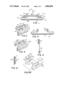
FIG. 1 is a front elevational view of a garment clamping hanger equipped with this invention;
FIG. 2 is a front elevational view of the auxiliary bar of this invention;
FIG. 3 is a fragmentary, oblique front view of the auxiliary bar secured to the hanger;
FIG. 4 is an enlarged, sectional elevational view taken along the plane IV--IV of FIG. 1;
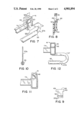
FIG. 5 is a fragmentary, oblique front view of a modified construction for the auxiliary bar;
FIG. 6 is a sectional elevational view taken along the plane VI--VI of FIG. 5;
FIG. 6A is an enlarged, fragmentary, exploded view of the auxiliary bar construction illustrated in FIG. 5;
FIG. 7 is an enlarged, fragmentary view of a further modification of this invention with the bar anchored to the hanger;
FIG. 8 is a fragmentary sectional view taken along the plane VIII--VIII of FIG. 7;
FIG. 9 is a fragmentary front view of the anchor end of the auxiliary bar illustrated in FIG. 7;
FIG. 10 is an end view of the auxiliary bar illustrated in FIG. 7;
FIG. 11 is a fragmentary view illustrating one method of securing to the hanger the auxiliary bar illustrated in FIG. 7; and
FIG. 12 is a fragmentary front view of a hanger with the auxiliary bar of FIG. 7 secured to it.
DESCRIPTION OF THE PREFERRED EMBODIMENT
Referring to FIG. 1, the numeral 10 identifies a conventional garment clamping hanger having an elongated body 11 supported at its center by a hook 12 and equipped at each end with a garment clamp 13. This hanger is one of the type described in U.S. Pat. No. 3,767,092, issued Oct. 23, 1973 to J. F. Garrison et al. The invention provides an auxiliary bar 20 which is designed to be detachably secured to the hanger body 10. The auxiliary bar has an article supporting, transverse member 21 which terminates in a pair of reversely bent end portions 22 which extend upwardly and inwardly and terminate in an anchor portion 23. Preferably, the length of the transverse member 21 is greater than that of the hanger 10 to receive a garment supported by the clamps 13. The length of the end portions 22 is such that the anchors 23 for securing the auxiliary bar to the hanger are located just inwardly of the clamps 13. The anchor portions are shaped to form a socket 24 defined by a pair of ears 25 which extend forwardly and terminate in vertically extending fingers which define a front opening which is less than the vertical height of the beam-like body 11. The auxiliary bar is molded of a plastic which has just enough resilience that the gap or opening between the ears 25 can be spread just enough to admit the beam-like body 11 of the hanger into the socket 24 where, because of this resilience, the beam will be clamped by the ears 25. Thus, the bar is detachably secured to the hanger and can be removed simply by spreading the ears to release it.
It will be noted that the bar is so designed that it seats against the rear face of the hanger with the sockets 24 extending forwardly. As is shown in FIG. 4, the end portions are located in the same vertical plane as the back of the sockets 24. Thus, the auxiliary bar is located in a plane which is rearwardly of the garment receiving chamber 27 of the clamps 13. Thus, the presence of the bar 21 does not interfere with the use and function of the clamps. This is important because the bar is intended to be an auxiliary feature to support an additional object, such as another garment, without in any way interfering with the normal function of the clamps. For example, the bar could be used to drape a pair of slacks with the slacks being gripped by the clamps but the distance the slacks would hang down from the hanger could be reduced because they can be folded to drape over the bar.
By making the bar detachable, the bar need be used only when it is required. Further, by making the hanger and the bar as two entirely separate and independent products, the complexity of the necessary molds is substantially reduced. In fact, since the hangers have long since been widely used commercially, only the bar needs to be manufactured to effect this improvement. It will be recognized that the shape of the garment supporting portion of the auxiliary bar can be designed to satisfy any of a number of different requirements because its length and particular cross-sectional shape can vary as needed. The reversely bent end sections can be simple rectangles with their greater dimension extending vertically, as will be observed from inspection of FIG. 3.
FIGS. 5, 6 and 6A illustrate a modification of the invention in which the sockets 24 are replaced by a pair of ears 30 and 31 with enlarged heads. The heads have oppositely facing, wedge-shaped portions 32 with an undercut 33 adjacent the forward face of the end portions 22a of the bar. These are designed to be pushed through an appropriate opening 34 in the vertical panel of the beam-like body 11 adjacent each of the clamps 13 (FIG. 6A). The ears are spaced sufficiently that they can be squeezed together just enough to be passed through the opening 34 and once through the opening, due to their resilience, they will separate to seat over the front face of the beam and, thus, lock the auxiliary bar 20a to the hanger body 11.
When the hanger body has top and bottom flanges to provide rigidity and load support, the end of the auxiliary bar 20a is long enough to engage and seat against both the upper and lower flanges of the body (FIG. 6). For this purpose, the base portions of the ears are lengthened to bridge the gap created by the auxiliary bar to seat against the flanges rather than the vertical web. This also has the beneficial effect of making the ears somewhat easier to push together when the auxiliary bar is to be attached or detached from the hanger.
FIGS. 7-11 illustrate a different approach to the attachment of an auxiliary bar to a clamping hanger. In this case, the hanger has somewhat different garment clamps at each end. In this construction, the rear leg 40 of a pinch-clip type clamp 41 is integral with the beam or body 11a of the hanger and the front leg 42 is secured to it by a web which functions as a hinge so located that it is substantially spaced from both the upper and lower ends of the legs 40 and 42. The upper portions of the legs form a grip by which the legs can be manipulated to open and close the clamp. The legs are biased to resiliently grip a garment by means of a spring 44 in a manner long known in the garment hanger field. That portion of the clamps which extends above the web which serves as the hinge about which the legs pivot form handles 45 by which the clamps can be manipulated. In many cases, the handle portions of the clamps have central openings 46. In this type of construction, the auxiliary bar 20b has a upstanding end portion which terminates in a T-shaped head 48 (FIG. 9). The head provides a pair of laterally extending tabs or ears 49, creating a head wider than the opening 46 through the handle portion of the rear leg. Because of the resiliency of the material from which the end portion 47 of the auxiliary bar is made, these ears can be squeezed together enough to be passed through the opening and then allowed to resume their natural spacing, thus securing the auxiliary bar to the rear leg. An alternative to this in some cases could be turning the head 48 diagonally of the opening enough to pass the tabs through as suggested in FIG. 11.
So that the lower portion of the reversely bent section 47 will lie closely against the back face of the rear leg, a score line or reduced thickness section 52 may be provided across the end portion just below the tabs to overcome any resilient stiffness which would tend to bias the lower portion of the auxiliary bar to project rearwardly.
As is suggested in FIGS. 7, 10 and 12, the rear bar need not necessarily be made of a single integral molded item. The ends can be molded or stamped from plastic material and then inserted in the end of a tubular member with a bonded or an interference fit or both. The tubular member could be plastic or plastic reinforced paper and thereby provide the desired rigidity to support the article and also provide a broad enough supporting surface that whatever is draped over it will not be creased by reason of its weight resting on the auxiliary bar. As is illustrated in FIG. 11, the auxiliary bar does not materially interfere with the appearance of the hanger from the front because its attachment to the hanger is concealed behind the lower portion of the clamp as is indicated in FIG. 12.
It will be seen that the invention provides a relatively inexpensive, easy to use, auxiliary bar which may be added to existing garment hangers of the clamping type. Further, it can be attached or removed easily and quickly and requires no modification of existing hangers of the clamping types. Thus, it provides a relatively inexpensive way of expanding the utility and convenience of existing clamping hangers, when such is desired.
Having described a preferred embodiment of the invention, together with modifications thereof, it will be understood that other modifications of the invention can be made without departing from the principles of the invention. Such modifications are to be considered as included in the hereinafter appended claims unless these claims by their language expressly state otherwise.

Claims (11)

I claim:
1. In combination an auxiliary garment support bar of molded plastic and a garment clamping hanger, said hanger having an elongated molded plastic body and support means therefor intermediate its ends, a pair of clamps, one on each side of said support means, said support bar having an elongated portion wider than the combined length of said body and clamps over which a garment can be draped, the end portions of said bar being shaped to extend upwardly and toward each other, said end portions being of rectangular cross-sectional shape and each having a greater dimension extending upwardly and generally parallel to the body of the hanger to support loads imposed on the support bar and the lesser dimension of said cross-sectional shape extending from front to back, permitting the end portions to seat against the rear face of the hanger body and the support bar to assume a position depending in a plane immediately behind the hanger body, the free ends of said end portions having anchor portions adapted to engage and be supported by said hanger body, said anchor portions being resiliently deflectable and having elements capable of interlocking with said hanger body.
2. The garment hanger and auxiliary garment support bar as described in claim 1 wherein said elements detachably interlock said hanger body.
3. The garment hanger and auxiliary garment support bar as described in claim 1 wherein said elongated support bar is a rigid bar having front and back faces and said anchor portions are resilient fingers shaped to form a socket of a size and shape to seat tightly over and clamp to said hanger body.
4. The garment hanger and auxiliary garment support bar as described in claim 2 wherein said fingers are shaped to form a C-shaped socket of a size to seat over and grip said hanger body.
5. The garment hanger and auxiliary garment support bar as described in claim 1 wherein said hanger body has a vertical panel, an opening through said panel adjacent each of said clamps, said elements being a pair of spaced ears integral with and extending forwardly from each said end portion, said ears having undercut portions adjacent their bases to receive and seat over the sides of a corresponding opening when said ears have been resiliently deflected toward each other and passed through said opening for detachably locking said support bar to said hanger body.
6. The garment hanger and auxiliary garment support bar as described in claim 1 wherein said clamps each have a pair of jaws one of which is integral and stationary with respect to said hanger body and the other is pivotably secured to said one jaw, said one jaw of each clamp being apertured, the ends of said anchor portions being provided with oppositely directed wings, said end portions being sufficiently resilient that said wings can be deflected to pass forwardly through said apertures and upon release seat against the front face of said hanger body on each side of the apertures to detachably secure the support bar to the hanger body.
7. An auxiliary garment support bar adapted to be detachably mounted on a garment hanger having a beam forming an elongated body with a garment clamp at each end, support means intermediate the ends of the body, said body being characterized by a vertical web, said body having an opening therethrough adjacent each of said clamps, said support bar having an elongated central portion and a pair of ends reversely curved in an upward direction, the terminal portion of each of said ends having a pair of spaced ears, said ears each having an undercut portion adjacent its base, said ears being resiliently deflectable toward each other to be passed through one of said openings in said web.
8. In combination, a garment hanger and a detachable auxiliary garment support bar depending therefrom, said hanger having a beam forming an elongated body with support means intermediate its ends, said body having a rigid vertical web and an article clamp on each end thereof; each of said clamps having a rear jaw and a front jaw, said jaws being pivotally joined with said rear jaw being integral with and supported in the same vertical plane as said body, said support bar having an elongated rigid central portion over which a garment can be draped and a pair of end portions, said end portions extending upwardly and toward each other, said body having an aperture adjacent each of said clamps, said end portions each having forwardly extending ears capable of being passed forwardly through one of said apertures, said ears seating against the forward face of said body and resiliently locking the support bar to said body.
9. In combination, a garment hanger and a detachable auxiliary garment support bar depending therefrom, said hanger having a beam forming an elongated body with support means intermediate its ends, said body having a rigid vertical web and an article clamp on each end thereof; each of said clamps having a rear jaw and a front jaw, said jaws being pivotally joined with said rear jaw being integral with and supported in the same vertical plane of said body, said support bar having an elongated rigid central portion over which a garment can be draped and a pair of end portions, said end portions extending upwardly and toward each other, said clamp having upwardly extending finger grips above the joinder thereof for maintaining the jaws, the finger grip of said rear jaw having an aperture therethrough, the terminal portion of each of said end portions of said support bar extending through said aperture into the space between said finger grips, said terminal portions each having oppositely and outwardly extending ears adapted to seat against the forward face of said finger grip of said rear jaw for detachably securing said auxiliary bar to said hanger.
10. The combination described in claim 9 wherein said terminal portions are sufficiently resilient to be deflected to pass through said apertures.
11. The combination described in claim 9 wherein said terminal portions below said ears have a line of reduced thickness extending thereacross serving as a hinge to permit the remainder of the auxiliary support bar to depend from said terminal portions in a plane immediately behind said beam.
US07/222,789 1988-07-22 1988-07-22 Snap on auxiliary bar for hangers Expired - Fee Related US4901894A (en)

Priority Applications (1)

Application Number Priority Date Filing Date Title
US07/222,789 US4901894A (en) 1988-07-22 1988-07-22 Snap on auxiliary bar for hangers

Applications Claiming Priority (1)

Application Number Priority Date Filing Date Title
US07/222,789 US4901894A (en) 1988-07-22 1988-07-22 Snap on auxiliary bar for hangers

Publications (1)

Publication Number Publication Date
US4901894A true US4901894A (en) 1990-02-20

Family

ID=22833685

Family Applications (1)

Application Number Title Priority Date Filing Date
US07/222,789 Expired - Fee Related US4901894A (en) 1988-07-22 1988-07-22 Snap on auxiliary bar for hangers

Country Status (1)

Country Link
US (1) US4901894A (en)

Cited By (20)

* Cited by examiner, † Cited by third party
Publication number Priority date Publication date Assignee Title
US5992714A (en) * 1997-09-22 1999-11-30 Batts, Inc. Width adjustable garment hanger and jam locking clamp means therefor
US20040004096A1 (en) * 2002-07-02 2004-01-08 Spotless Plastics Pty. Ltd. Auxiliary bar for a hanger
GB2391463A (en) * 2002-08-07 2004-02-11 Nick Andrew Lewis Adjustable garment hanger
US20070075104A1 (en) * 2005-10-05 2007-04-05 Yau Wai S Pinch Clip Garment Hanger
US20070158373A1 (en) * 2006-01-10 2007-07-12 Wai Shing Yau Garment hanger with releasable information tab
US20070158375A1 (en) * 2006-01-12 2007-07-12 Wai Shing Yau Garment hanger with dependent loop and accessory hanger
US20070228088A1 (en) * 2006-04-12 2007-10-04 Yau Wai S Pinch clip garment hanger with modular friction pads
US20100032456A1 (en) * 2008-08-06 2010-02-11 Thor Daniel W System for flexible displaying of objects
US20100307936A1 (en) * 2009-06-09 2010-12-09 Target Brands, Inc. Hanging display package and associated products and methods
USD648142S1 (en) 2009-11-02 2011-11-08 Target Brands, Inc. Hanger portion
US8444029B2 (en) 2011-03-08 2013-05-21 Target Brands, Inc. Reinforced hanger and associated packaged product assembly
USD805791S1 (en) 2016-08-29 2017-12-26 Target Brands, Inc. Hanger
US10683603B1 (en) * 2016-12-01 2020-06-16 David Lee Henry Clothes drying system
USD955764S1 (en) * 2021-01-12 2022-06-28 The Container Store, Inc. Clothes hanger for pants and skirts
USD956866S1 (en) 2021-01-12 2022-07-05 The Container Store, Inc. Desktop file
USD956865S1 (en) 2021-01-12 2022-07-05 The Container Store, Inc. Pencil organizer
USD956864S1 (en) 2021-01-12 2022-07-05 The Container Store, Inc. Desktop organizer
US11633057B2 (en) * 2017-06-09 2023-04-25 Jessica Davidoff Compact garment hanger
USD1001888S1 (en) 2021-01-12 2023-10-17 The Container Store, Inc. Magazine file
USD1005998S1 (en) 2021-01-12 2023-11-28 The Container Store, Inc. Monitor riser

Citations (9)

* Cited by examiner, † Cited by third party
Publication number Priority date Publication date Assignee Title
US2822967A (en) * 1954-08-02 1958-02-11 Spitz Henry Garment supporting device
US2970726A (en) * 1956-11-13 1961-02-07 Norman E Brooke Garment hangers
US3157325A (en) * 1962-11-23 1964-11-17 Central Specialty Co Display hanger
US3165245A (en) * 1963-07-12 1965-01-12 Warbern Plastics Inc Double hanger
US3350754A (en) * 1966-03-25 1967-11-07 Central Specialties Company Flexible clothing clamp structure
US3471069A (en) * 1968-08-23 1969-10-07 Frank Simon Adjustable garment hangers
US3744685A (en) * 1971-06-14 1973-07-10 Grace W R & Co Hanger for trousers
US3767092A (en) * 1972-01-31 1973-10-23 Thomas Batts Inc J Garment clamping hanger with slidable locking clip
US4759480A (en) * 1987-06-11 1988-07-26 Batts, Inc. Garment hanger with auxiliary bar

Patent Citations (9)

* Cited by examiner, † Cited by third party
Publication number Priority date Publication date Assignee Title
US2822967A (en) * 1954-08-02 1958-02-11 Spitz Henry Garment supporting device
US2970726A (en) * 1956-11-13 1961-02-07 Norman E Brooke Garment hangers
US3157325A (en) * 1962-11-23 1964-11-17 Central Specialty Co Display hanger
US3165245A (en) * 1963-07-12 1965-01-12 Warbern Plastics Inc Double hanger
US3350754A (en) * 1966-03-25 1967-11-07 Central Specialties Company Flexible clothing clamp structure
US3471069A (en) * 1968-08-23 1969-10-07 Frank Simon Adjustable garment hangers
US3744685A (en) * 1971-06-14 1973-07-10 Grace W R & Co Hanger for trousers
US3767092A (en) * 1972-01-31 1973-10-23 Thomas Batts Inc J Garment clamping hanger with slidable locking clip
US4759480A (en) * 1987-06-11 1988-07-26 Batts, Inc. Garment hanger with auxiliary bar

Cited By (25)

* Cited by examiner, † Cited by third party
Publication number Priority date Publication date Assignee Title
US5992714A (en) * 1997-09-22 1999-11-30 Batts, Inc. Width adjustable garment hanger and jam locking clamp means therefor
US20040004096A1 (en) * 2002-07-02 2004-01-08 Spotless Plastics Pty. Ltd. Auxiliary bar for a hanger
US6988643B2 (en) * 2002-07-02 2006-01-24 Spotless Plastics Pty. Ltd. Auxiliary bar for a hanger
GB2391463A (en) * 2002-08-07 2004-02-11 Nick Andrew Lewis Adjustable garment hanger
GB2391463B (en) * 2002-08-07 2005-09-28 Nick Andrew Lewis Adjustable garment hanger with adjustable width skirt clips
US20070075104A1 (en) * 2005-10-05 2007-04-05 Yau Wai S Pinch Clip Garment Hanger
US20070158373A1 (en) * 2006-01-10 2007-07-12 Wai Shing Yau Garment hanger with releasable information tab
US20070158375A1 (en) * 2006-01-12 2007-07-12 Wai Shing Yau Garment hanger with dependent loop and accessory hanger
US7628302B2 (en) 2006-01-12 2009-12-08 Wai Shing Yau Garment hanger with dependent loop and accessory hanger
US20070228088A1 (en) * 2006-04-12 2007-10-04 Yau Wai S Pinch clip garment hanger with modular friction pads
US7537142B2 (en) 2006-04-12 2009-05-26 Wai Shing Plastic Products Ltd. Pinch clip garment hanger with modular friction pads
US20100032456A1 (en) * 2008-08-06 2010-02-11 Thor Daniel W System for flexible displaying of objects
US20100307936A1 (en) * 2009-06-09 2010-12-09 Target Brands, Inc. Hanging display package and associated products and methods
US7984803B2 (en) * 2009-06-09 2011-07-26 Target Brands, Inc. Hanging display package and associated products and methods
USD648142S1 (en) 2009-11-02 2011-11-08 Target Brands, Inc. Hanger portion
US8444029B2 (en) 2011-03-08 2013-05-21 Target Brands, Inc. Reinforced hanger and associated packaged product assembly
USD805791S1 (en) 2016-08-29 2017-12-26 Target Brands, Inc. Hanger
US10683603B1 (en) * 2016-12-01 2020-06-16 David Lee Henry Clothes drying system
US11633057B2 (en) * 2017-06-09 2023-04-25 Jessica Davidoff Compact garment hanger
USD955764S1 (en) * 2021-01-12 2022-06-28 The Container Store, Inc. Clothes hanger for pants and skirts
USD956866S1 (en) 2021-01-12 2022-07-05 The Container Store, Inc. Desktop file
USD956865S1 (en) 2021-01-12 2022-07-05 The Container Store, Inc. Pencil organizer
USD956864S1 (en) 2021-01-12 2022-07-05 The Container Store, Inc. Desktop organizer
USD1001888S1 (en) 2021-01-12 2023-10-17 The Container Store, Inc. Magazine file
USD1005998S1 (en) 2021-01-12 2023-11-28 The Container Store, Inc. Monitor riser

Similar Documents

Publication Publication Date Title
US4901894A (en) Snap on auxiliary bar for hangers
US4759480A (en) Garment hanger with auxiliary bar
US5361949A (en) Pants hanger with pivotable finger on lower bar
CA1167425A (en) Pant hanger with internal spring
US4192441A (en) Clamp construction for article hangers
US4807334A (en) Article hanger clip
US4023762A (en) Article suspension device
US4826056A (en) Hanger with adjustable garment clamps
US6622897B2 (en) Pinch-grip hanger
US4871097A (en) Display hanger with finger clamps
US20190246825A1 (en) Improvement relating to clothes hangers
US4889265A (en) Folding pant hanger
US2805013A (en) Garment hanger
US4884727A (en) Hanger with snap-on adjustable clips
US5562237A (en) Trousers hanger
US4600132A (en) Adjustable hanger
US5054666A (en) Belt display hanger
US2846128A (en) Garment hanger
GB2198340A (en) Sliding clamp garment hanger
US2494727A (en) Coat hanger trouser holding attachment
US5950885A (en) Garment hanger with reinforced non-creep clamp retainers
JPH024632Y2 (en)
JPS6026688Y2 (en) hanger
IE921479A1 (en) A hanger
EP1471805B1 (en) Pinch-grip hanger

Legal Events

Date Code Title Description
AS Assignment

Owner name: RICOH COMPANY, LTD., NO. 3-6, 1-CHOME, NAKAMAGOME,

Free format text: ASSIGNMENT OF ASSIGNORS INTEREST.;ASSIGNOR:BLANCHARD, RUSSELL O.;REEL/FRAME:004926/0831

Effective date: 19880721

Owner name: BATTS, INC., 200 N. FRANKLIN ZEELAND, MI 49464 A C

Free format text: ASSIGNMENT OF ASSIGNORS INTEREST.;ASSIGNOR:BLANCHARD, RUSSELL O.;REEL/FRAME:004926/0819

Effective date: 19880714

FEPP Fee payment procedure

Free format text: PAT HLDR NO LONGER CLAIMS SMALL ENT STAT AS SMALL BUSINESS (ORIGINAL EVENT CODE: LSM2); ENTITY STATUS OF PATENT OWNER: LARGE ENTITY

FPAY Fee payment

Year of fee payment: 4

REMI Maintenance fee reminder mailed
LAPS Lapse for failure to pay maintenance fees
FP Lapsed due to failure to pay maintenance fee

Effective date: 19980225

STCH Information on status: patent discontinuation

Free format text: PATENT EXPIRED DUE TO NONPAYMENT OF MAINTENANCE FEES UNDER 37 CFR 1.362