US4966588A - Device suitable for the administration of a therapeutic substance - Google Patents
Device suitable for the administration of a therapeutic substance Download PDFInfo
- Publication number
- US4966588A US4966588A US07/170,383 US17038388A US4966588A US 4966588 A US4966588 A US 4966588A US 17038388 A US17038388 A US 17038388A US 4966588 A US4966588 A US 4966588A
- Authority
- US
- United States
- Prior art keywords
- hub
- cannula
- needle
- passage
- separator means
- Prior art date
- Legal status (The legal status is an assumption and is not a legal conclusion. Google has not performed a legal analysis and makes no representation as to the accuracy of the status listed.)
- Expired - Fee Related
Links
Images


Classifications
-
- A—HUMAN NECESSITIES
- A61—MEDICAL OR VETERINARY SCIENCE; HYGIENE
- A61M—DEVICES FOR INTRODUCING MEDIA INTO, OR ONTO, THE BODY; DEVICES FOR TRANSDUCING BODY MEDIA OR FOR TAKING MEDIA FROM THE BODY; DEVICES FOR PRODUCING OR ENDING SLEEP OR STUPOR
- A61M39/00—Tubes, tube connectors, tube couplings, valves, access sites or the like, specially adapted for medical use
- A61M39/02—Access sites
- A61M39/06—Haemostasis valves, i.e. gaskets sealing around a needle, catheter or the like, closing on removal thereof
- A61M39/0606—Haemostasis valves, i.e. gaskets sealing around a needle, catheter or the like, closing on removal thereof without means for adjusting the seal opening or pressure
-
- A—HUMAN NECESSITIES
- A61—MEDICAL OR VETERINARY SCIENCE; HYGIENE
- A61M—DEVICES FOR INTRODUCING MEDIA INTO, OR ONTO, THE BODY; DEVICES FOR TRANSDUCING BODY MEDIA OR FOR TAKING MEDIA FROM THE BODY; DEVICES FOR PRODUCING OR ENDING SLEEP OR STUPOR
- A61M5/00—Devices for bringing media into the body in a subcutaneous, intra-vascular or intramuscular way; Accessories therefor, e.g. filling or cleaning devices, arm-rests
- A61M5/14—Infusion devices, e.g. infusing by gravity; Blood infusion; Accessories therefor
- A61M5/158—Needles for infusions; Accessories therefor, e.g. for inserting infusion needles, or for holding them on the body
-
- A—HUMAN NECESSITIES
- A61—MEDICAL OR VETERINARY SCIENCE; HYGIENE
- A61M—DEVICES FOR INTRODUCING MEDIA INTO, OR ONTO, THE BODY; DEVICES FOR TRANSDUCING BODY MEDIA OR FOR TAKING MEDIA FROM THE BODY; DEVICES FOR PRODUCING OR ENDING SLEEP OR STUPOR
- A61M39/00—Tubes, tube connectors, tube couplings, valves, access sites or the like, specially adapted for medical use
- A61M39/02—Access sites
- A61M39/06—Haemostasis valves, i.e. gaskets sealing around a needle, catheter or the like, closing on removal thereof
- A61M2039/0633—Haemostasis valves, i.e. gaskets sealing around a needle, catheter or the like, closing on removal thereof the seal being a passive seal made of a resilient material with or without an opening
Definitions
- the present invention relates to a device suitable for the administration of a therapeutic substance, for example insulin, especially but not necessarily on an intermittent basis.
- Insulin-dependent diabetics rely upon subcutaneous doses of insulin administered, and usually self-administered, by means of a syringe and a hypodermic needle. This involves the psychological trauma of self-injection, as well as the inconvenience of the overall procedure. Insulin may also be delivered by electrical, mechanical or hand-operated pumps.
- indwelling needle through which insulin may be administered.
- the facility to give injections via indwelling needles is not new (see, for example U.S. Pat. No. 4,568,335), but there are two problems with such indwelling needles as currently available.
- the needles are sharp and made of rigid steel, which can be painful in situ; and secondly, in the injection port attached to the needle there is a large "dead-space", that is the space in the device within which insulin will be withheld instead of being expressed to the patient, which gives rise to problems not merely the problems involved in taking account of the dead-space when calculating doses of insulin, but also the further problems which arise when injecting more than one species of insulin.
- the kind of needles employed for this purpose and their associated apparatus are often designed for giving large volumes of solution, or for sampling blood. Still further, as shown for example in the above-mentioned United States Patent Specification the connection between the feed syringe or the like and the needle cannot be broken, since there is no seal in or associated with the needle itself.
- buttons infuser In an effort to eliminate dead-space problems, there has been marketed in the U.K. a so-called “button” infuser, which is said to have a nominal "dead-space” volume of less than 0.33 units of U-100 insulin.
- "button” infuser again has a steel needle, leading to discomfort; and, while this device is self sealing, it is difficult to ensure that the intermittent injection needle (which has to be inserted into the indwelling needle) is always during its insertion accurately placed, so that first it does not over-penetrate and engage the plastics material in the hub of the indwelling needle, and so that secondly it does not under-penetrate and fail to enter the indwelling needle lumen beyond the self-sealing diaphragm.
- the present invention provides a device suitable for use in the intermittent or even continuous administration of a therapeutic substance (such as insulin), which device comprises a cannula of biocompatible plastics material for indwelling in a patient and defining a through-passage (lumen), together with a hub also defining a through-passage, the respective cannula and hub passages being isolatable from each other by separator means (such as a self-sealing diaphragm) disposed between them, the arrangement of the respective passages themselves and together with said separator means being such as to permit a needle to penetrate the hub and cannula through them and, when necessary, to extend beyond the distal end of the cannula, the through-passage of the hub also being so constructed and arranged as to guide an injection needle passed therethrough so that the needle thus guided will pass through the separator means at a position where the needle is aligned with the through passage of the cannula.
- separator means such as a self-sealing diaphrag
- the device of the invention can be positioned with its cannula implanted subcutaneously in the patient by means of a skin-puncture needle which may be already disposed in the device or inserted therein when required, and which extends beyond the distal end of the cannula
- a skin-puncture needle which may be already disposed in the device or inserted therein when required, and which extends beyond the distal end of the cannula
- the skin-puncture needle is withdrawn, and the device can be taped in place to be left in situ for use in the administration of one or more doses of insulin or the like as necessary.
- the device may be left in situ for four days, and over that period of time up to 16 doses or more of insulin may be injected through the device, effectively involving only the single initial skin puncture.
- the needle of a hypodermic syringe containing the insulin or the like is passed along the through-passage in the hub. Once it reaches the end of that passage, the needle passes through the separator means. Preferably, its movement past a position where its tip is just beyond the separator means is then prevented by including in the device of the invention over penetration-restraining means. Conveniently, this can be accomplished by arranging the hub so that the overall penetrable length of the through-passage therein is just a little shorter than a standard hypodermic needle. For example, one typical standard hypodermic needle for insulin injection is an 11 mm needle.
- the through passage in the cannula and the through-passage in the hub are separated by separator means.
- separator means any suitable separator means could be employed, for example mechanical separator means such as a valve, it is in practice generally preferred to employ a self sealing diaphragm.
- a diaphragm may comprise a variety of self-sealing elastomeric materials, for example, natural rubber, silicone rubber or a suitable grade of any other elastomeric polymer.
- a hub having a through-passage and which includes a self-sealing diaphragm or like separator means at the distal end of the passage adjacent the entrance to the cannula
- accurate placement of the injection needle can be accomplished.
- the length of the hub can be chosen so that the desired amount of penetration of the diaphragm or the like is achieved, but no more.
- the nominal "deadspace” volume generally may be any chosen volume of about 0.75 units of U-100 insulin or below.
- larger “dead-space” volumes may be chosen--since notionally at least the self-sealing diaphragm or the like always holds a small volume of insulin in the cannula passage beyond the diaphragm seal--nevertheless because "dead-space” volumes of about 0.75 units of U-100 insulin or below are easily achieved with the device of the invention, as described herein, and because the smaller the "dead-space” volume the more flexible the device can be in terms of the ability to avoid the need to flush when changing insulin dosage or species, "deadspace” volumes below the figure stated above are generally preferred. More preferably, however, the "dead-space” volume should be in the range of from about 0.5 to about 0.3 units of U-100 insulin.
- the mouth of the through-passage in the hub most remote from the cannula is desirably so shaped that the passage has a conical or funnelled entrance zone.
- a conical or funnelled entrance zone By providing a conical or funnelled entrance zone, penetration of the mouth of the through-passage in the hub by the hypodermic needle is facilitated even when the cannula is positioned in situ, and even though the patient's view of the mouth of the through-passage may be restricted.
- the conical or funnelled entrance zone provides a guide portion permitting easy penetration of the mouth of the through-passage even where the passage mouth is covered, as is preferred, by a self-sealing cap or the like, as described below. It will be appreciated that ingress of dirt or other undesirable material into the device can be avoided if the hub includes means such as a cap to prevent such ingress.
- the device of the invention generally may remain in situ for a period in the region of about 4 days, with a typical period being say from about 2 to about 5 days. Since the device includes a cannula of biocompatible plastics material, irritation generally is kept to a minimum, and the plastics cannula is thus less noticeable to the wearer once placed in situ than a corresponding steel cannula. Moreover, the patient can feel confident once the device is in situ that the next-following series of injections (say 16 or more further injections) can be accomplished without trauma and, furthermore, that no insulin loss will occur. That is because the injection needle is securely guided to proper placement in the injection port, and generally cannot be misdirected or misplaced.
- the cannula comprises a flexible synthetic plastics material, generally formed of one or more synthetic polymers, for example, of one or more fluorocarbons such as "Teflon". It is of course especially preferred that the cannula should comprise a medical-implant grade synthetic polymer. In addition, it is also preferred that the hub should comprise a biocompatible material suitable for use with drugs and next to skin. Examples of such materials are polypropylene and polyurethane materials.
- the hub is preferably a two-part hub-assembly, preferably with the separator means located between the two parts of the hub.
- a first hub-component comprises a body defining an axial bore which at its distal end is adapted to receive the proximal end of the cannula, whereby the through-passage of the cannula is positioned in communication with the bore, and at its other end a socket communicating with the bore and adapted to receive (mate with) a plug portion of a second hub-component, also comprising a body defining an axial bore, the bores in the respective first and second hub-components being aligned to communicate with each other and together defining the through-passage in the hub assembly
- a self-sealing diaphragm can then be sandwiched between the two hub-components e.g. between the distal end of the plug-portion and the base of the socket
- the first hub-component includes an elongated nose portion at its distal end, within which a significant portion of the proximal end of the cannula can be accommodated, thereby providing support for the cannula and a means of securing the cannula to the hub, for example, by adhering the outside of the cannula to the inside of the nose.
- the bore in the first hub-component may be of greater diameter than the diameter of the through-passage, where it accommodates the tip of the proximal end of the cannula, thus providing an annular abutment for the tip of the proximal end of the cannula, to permit securing of the cannula to the hub.
- the cannula can advantageously be shaped at its distal tip so that it tapers towards and close to the projecting tip of a skin-puncture needle (when the latter is disposed within the device, to enable it to penetrate the skin), and so that its front edges are relatively smooth.
- the hub of the device may include a self-adhesive support portion to enable the hub to adhere to the patient's skin when pressed thereagainst.
- the device of this invention has been described above mainly in relation to its use with insulin, but it is to be understood that its utility is not necessarily confined to the administration of insulin but extends to the administration of any therapeutic substance which requires the patient to be injected (or above all to inject himself) frequently--say a number of times in each day. Thus, for instance, the device can prove valuable in the regular administration of morphine.
- the device has been primarily designed and therefore is particularly suitable for self-administration on an intermittent basis, it should be appreciated that it may also be used in conjunction with apparatus for continuous administration.
- the hub may be adapted to be connected to means continuously to supply a therapeutic substance such as insulin or morphine.
- a therapeutic substance such as insulin or morphine.
- Such means are currently available and comprise a reservoir, a pump, a supply line and a needle for injection purposes.
- various kinds of sophisticated electronic means may be included to achieve any necessary or desired control over the doses pumped from the reservoir to the needle via the supply line.
- the device preferably will include a hub having means to provide or accommodate a supply line lock fitment.
- the hub may be formed with say one or more Luer lock lugs, or with means to accommodate say a Luer lock adaptor.
- the hub is of a two part hub-assembly as described previously, and the hub components are arranged so that the plug-portion of the second hub-component includes an annular flange, and the plug-portion mates with the socket in the first hub-component in such a manner that an annular locking groove is formed between the flange and the end of the first hub-component adjacent the flange
- annular groove may be used to accommodate the front arms of a clip, for example, a hinged clip like that described in co-pending British Patent Application No. 85-17976 (Publication No. 2,161,709A) and European Patent Application No. 85-30-5093.8 (Publication No. EP 0169704A).
- a said clip may be defined as one having a body portion including at or adjacent one end means, such as a pair of opposed depending arms, engageable with the supply line or supply line connector, and at or adjacent its other end a pair of opposed depending arms engageable with the groove, the said means being arranged to permit the said arms engageable with the groove to move into and out of engagement.
- such a clip may be one for use with a supply line which includes a pair of trunnion pins upstanding on either side of an end portion of the line.
- the clip then may be formed with a first pair of opposed arms each including an aperture so that they can be sprung over the trunnion pins and the clip thereby pivotably mounted on the end portion of the line.
- the invention also includes a device as defined and described herein in combination with a skin puncture needle. Such a combination may be put up for use packaged together with the needle disposed in the device in a sterile pack.
- the pack preferably will include a self-sealing cap as described herein to prevent ingress of dirt in use.
- the invention includes a device as defined and described herein in combination with a supply line arrangement.
- the supply line arrangement includes mounted on an end portion of the line a needle adapted to penetrate the separator means of the device and a pivotal clip engageable with the hub of the device to lock together the device and the supply line.
- the hub may be a two-part hub-assembly as described above with an annular locking groove and the clip may be as defined above.
- the supply line arrangement may include a reservoir and/or a pump and/or electronic control means as described above.
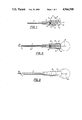
- FIG. 1 is a mainly cross-sectional view, taken in a plane through the axis, of an embodiment of the device of the invention
- FIG. 2 is an essentially similar, mainly cross sectional view, of the embodiment of FIG. 1, again taken in a plane through the axis of the device, showing a cap-like closure member mounted thereon to prevent ingress of dirt, and a skin-penetration needle fitted therethrough in its operative, skin-penetrating position;
- FIG. 3 is a non-sectional external view of the embodiment of FIG. 2, taken in slight perspective from the distal end of the skin-penetration needle;
- FIG. 4 is a mainly cross-sectional view of the same embodiment of the device, generally similar to FIG. 2 but on an enlarged scale, and in which the skin-penetration needle has been removed and replaced by the hypodermic injection needle of a syringe;
- FIG. 5 is a diagrammatic side view of a combination of a device in accordance with the invention shown in unlocked association with a supply line arrangement;
- FIG. 5(a) shows the clip of FIG. 5 separate from the supply line arrangement
- FIG. 6 shows the combination of FIG. 5 locked together.
- the device shown comprises a cannula 1 having a delivery (through) passage or lumen 16.
- the cannula is formed of biocompatible flexible synthetic plastics material and, therefore, is capable of indwelling in a patient for a period of several days after subcutaneous insertion thereof.
- the proximal end of the cannula 1 is mounted and secured (e.g. by adhesive) at the distal end of a two-part hub assembly, generally indicated by the numeral 2, also formed of a biocompatible but relatively rigid plastics material, and having a through-passage 3 passing axially therethrough which communicates with the delivery passage or lumen 16 within the cannula 1.
- the hub-assembly 2 comprises a first hub-component 4 and a second hub-component 5, each having an axially-disposed bore therein which, in the assembled position (as shown), is aligned with the axially-disposed bore in the other hub-component, and which together constitute the through-passage 3.
- the hub assembly 2 is formed by mating a cylindrical socket 6 in the proximal end of the first hub-component 4 with a plug-portion 7 on the distal end of the second hub-component 5.
- An annular collar 17 around hub-component 5 prevents the plug portion 7 from mating fully with the socket 6 in the first hub-component 4 and, within the cylindrical chamber between the base of the socket 6 and the end of the plug-portion 7, there is accommodated a self-sealing diaphragm 8, formed of silicone rubber or another elastomeric polymer.
- the diaphragm 8 is thus sandwiched between the hub-components 4 and 5, blocking communication between the axial bores therein and thus normally sealing the through-passage 3.
- the diaphragm 8 may easily be penetrated by a needle which is passed down the through-passage 3 to penetrate through the diaphragm.
- a skin-penetration needle 14 (see FIGS. 2 and 3) is passed through the device down through-passage 3 until its tip protrudes beyond the distal end of cannula 1. It will be seen that, in order to ease the implantation of the cannula 1 subcutaneously into the patient, its distal end 1' is externally tapered and fitted as closely as possible about the protruding end of the skin-penetration needle 14.
- the proximal end of the second hub-component 5 is provided with an open-mouthed, conical indent generally designated by the numeral 9, whose conical walls 9' are co-axial with and whose apex communicates with the through-passage 3.
- an open-mouthed, conical indent generally designated by the numeral 9, whose conical walls 9' are co-axial with and whose apex communicates with the through-passage 3.
- a skin-penetration needle (FIG. 2) or a hypodermic injection needle (FIG. 4) entering the device is funnelled into alignment with the through passage 3 by this open-mouthed conical indent 9.
- a tubular-skirted cap generally indicated by the numeral 10, and formed of elastomeric material, is removably fitted across the otherwise open mouth of the conical indent 9. There it is held in position by its depending tubular walls 11 adapted to embrace part of the cylindrical outer surface of the main body portion of the second hub-component 5.
- the distal end of the latter, adjacent the plug portion 7, is provided with an annular groove 12, within which there is accommodated a bulbous sealing ring 13 formed around the skirt-edges of the tubular walls 11 of the cap 10.
- a skin-penetration needle 14 (see FIGS. 2 and 3) is passed through the cap 10, funnelled by the conical indent 9 into the through-passage 3 and, after piercing the self-sealing diaphragm 8, enters and passes through the lumen 16 of the cannula 1, until it extends somewhat beyond the tapered distal end 1' thereof.
- the skin-penetration needle thus located, the cannula 1 the device is then subcutaneously implanted in the patient, the hub-assembly 2 is taped or otherwise secured in place upon the patient (e.g. his abdomen) and the skin-penetration needle is withdrawn, leaving the device indwelling in the patient. There it may remain for several days ready for intermittent or continuous use, as required, for the administration (especially the self-administration) of insulin, morphine or any other therapeutic substance.
- the needle of the hypodermic injection syringe containing the substance is, as shown in FIG. 4, passed in a similar manner through the cap 10. Again the needle is funnelled by conical indent 9 into the through-passage 3, and then pierces the self sealing diaphragm 8, but this time is there arrested when the syringe-body 15 abuts against the cap 10.
- the hypodermic injection syringe is placed in an ideal location adjacent the end of the cannula 1 for the discharge of therapeutic substance from the syringe to the patient through the device.
- the supply line arrangement includes a supply line 23 e.g. a fine bore line, through which a therapeutic substance such as insulin or morphine may be fed e.g. by a pump arrangement, and an end portion 24.
- the end portion 24 includes a needle 25 e.g. corresponding to the needle of the syringe shown in FIG. 4, and a pair of trunnion pins 26 (only one shown).
- the locking clip 27 comprises a body portion 28 having a first pair of opposed depending arms 29 engageable with the trunnion pins 26 via through apertures 31 whereby the clip 27 can be pivotably mounted on the end portion 24 as shown.
- the body portion 28 also has a nose portion 32 and a second pair of opposed depending arms 33 which are engageable with annular groove 12 (see also FIG. 4) when the needle 25 is passed into the device 21 so that a configuration of needle and device the same as or similar to that shown in FIG. 4 is achieved.
- the supply line arrangement 22 and the device 21 may be locked together as shown in FIG. 6 so that the patient may receive a therapeutic substance through the line 23. Thereafter, when treatment is complete the combination may be unlocked by inserting a finger under nose portion 32 and lifting the arms 33 out of engagement with the annular groove 12, thus releasing the device 21 from the supply line arrangement 22.
- the invention provides a device in which accurate placement of the injecting or like needle can be accomplished both in terms of alignment and in terms of penetration.
- accurate placement in terms of alignment is achieved by providing in accordance with the preferred embodiments described above a hub defining a through-passage so constructed and arranged that the needle is constrained by the diameter of at least part of the through-passage and its alignment with the cannula lumen so that it must enter the lumen as it passes through the self-sealing diaphragm or other separator means rather than penetrate the cannula wall or otherwise be misaligned.
- the respective cannula and hub through-passages being at least essentially the same in diameter and at least essentially axially aligned lead to the desired accurate placement.
- the body of clip 27 may be longer and arms 33 may engage the device 21 nearer its distal end e.g. in another annular groove formed therein beyond groove 12. In that manner the cap 10 may be left in situ in the combination of FIGS. 5 to 6.
- other arrangements may be employed and numerous variations may be made within the spirit of the invention defined by the scope of the claims which follow.
Abstract
Description
Claims (22)
Applications Claiming Priority (2)
| Application Number | Priority Date | Filing Date | Title |
|---|---|---|---|
| GB868618253A GB8618253D0 (en) | 1986-07-25 | 1986-07-25 | Intermittent administration of therapeutic substance |
| GB8618253 | 1986-07-25 |
Publications (1)
| Publication Number | Publication Date |
|---|---|
| US4966588A true US4966588A (en) | 1990-10-30 |
Family
ID=10601725
Family Applications (1)
| Application Number | Title | Priority Date | Filing Date |
|---|---|---|---|
| US07/170,383 Expired - Fee Related US4966588A (en) | 1986-07-25 | 1987-07-24 | Device suitable for the administration of a therapeutic substance |
Country Status (8)
| Country | Link |
|---|---|
| US (1) | US4966588A (en) |
| EP (1) | EP0256694B1 (en) |
| AT (1) | ATE78180T1 (en) |
| AU (1) | AU7760087A (en) |
| DE (1) | DE3780378T2 (en) |
| ES (1) | ES2033855T3 (en) |
| GB (2) | GB8618253D0 (en) |
| WO (1) | WO1988000842A1 (en) |
Cited By (118)
| Publication number | Priority date | Publication date | Assignee | Title |
|---|---|---|---|---|
| US5064414A (en) * | 1989-07-28 | 1991-11-12 | Angeion Corporation | Locking clip with sheath and dilator |
| US5122120A (en) * | 1989-08-31 | 1992-06-16 | H G Wallace Ltd. | Intravascular placement apparatus |
| US5167636A (en) * | 1991-10-24 | 1992-12-01 | Mectra Labs, Inc. | Cannula sealing mechanism |
| US5180373A (en) * | 1991-06-07 | 1993-01-19 | United States Surgical Corporation | Valve system for introducing objects into anatomical body portions |
| WO1993001850A1 (en) * | 1991-07-18 | 1993-02-04 | Applied Medical Resources Corporation | Lever actuated septum seal |
| US5188607A (en) * | 1991-11-12 | 1993-02-23 | Thomas Wu | Valve catheter connector assembly |
| US5211634A (en) * | 1991-08-06 | 1993-05-18 | Vaillancourt Vincent L | Composite seal structure and a coupling arrangement for a cannula |
| US5230707A (en) * | 1988-07-21 | 1993-07-27 | Maurice Laderoute | Limited use hypodermic syringe |
| US5257980A (en) * | 1993-04-05 | 1993-11-02 | Minimed Technologies, Ltd. | Subcutaneous injection set with crimp-free soft cannula |
| US5284474A (en) * | 1990-12-11 | 1994-02-08 | Adair Edwin Lloyd | Trochar system for laparoscopy |
| US5312362A (en) * | 1993-02-04 | 1994-05-17 | Owens Precision Systems, Inc. | Seal for a cannula assembly |
| US5334164A (en) * | 1992-01-03 | 1994-08-02 | United States Surgical Corporation | Variable interior dimension cannula assembly |
| US5376073A (en) * | 1992-11-23 | 1994-12-27 | Becton, Dickinson And Company | Locking safety needle assembly |
| US5380301A (en) * | 1992-07-10 | 1995-01-10 | Sherwood Medical Company | Catheter/hub strain relief and method of manufacture thereof |
| US5385553A (en) * | 1991-07-18 | 1995-01-31 | Applied Medical Resources Corporation | Trocar with floating septum seal |
| US5391154A (en) * | 1993-08-30 | 1995-02-21 | United States Surgical Corporation | Trocar seal system |
| US5441487A (en) * | 1993-11-30 | 1995-08-15 | Medex, Inc. | Plastic needleless valve housing for standard male luer locks |
| US5496274A (en) * | 1992-11-23 | 1996-03-05 | Becton, Dickinson And Company | Locking safety needle assembly |
| US5549566A (en) * | 1994-10-27 | 1996-08-27 | Abbott Laboratories | Valved intravenous fluid line infusion device |
| US5554123A (en) * | 1994-10-31 | 1996-09-10 | Glenn Herskowitz | Portable infusion pump |
| US5578059A (en) * | 1993-11-30 | 1996-11-26 | Medex, Inc. | Anti-reflux valve with environmental barrier |
| US5603702A (en) * | 1994-08-08 | 1997-02-18 | United States Surgical Corporation | Valve system for cannula assembly |
| US5657963A (en) * | 1993-06-16 | 1997-08-19 | United States Surgical Corporation | Seal assembly for accommodating introduction of surgical instruments |
| US5752938A (en) * | 1994-09-12 | 1998-05-19 | Richard-Allan Medical Industries, Inc. | Seal for surgical instruments |
| US5782807A (en) * | 1995-10-20 | 1998-07-21 | Tfx Medical Incorporated | Releasably locking introducer devices |
| US5800398A (en) * | 1995-04-28 | 1998-09-01 | Richard Wolf Gmbh | Method and apparatus for positioning operating tubes |
| US5827228A (en) * | 1991-10-18 | 1998-10-27 | Ethicon, Inc. | Seal members for surgical trocars |
| US5951518A (en) * | 1997-10-31 | 1999-09-14 | Teleflex, Incorporated | Introducing device with flared sheath end |
| US5957898A (en) | 1997-05-20 | 1999-09-28 | Baxter International Inc. | Needleless connector |
| US5968011A (en) * | 1997-06-20 | 1999-10-19 | Maersk Medical A/S | Subcutaneous injection set |
| US6066117A (en) * | 1996-06-11 | 2000-05-23 | Endolap, Inc. | Cannula flapper valve assembly |
| US6071265A (en) * | 1997-03-26 | 2000-06-06 | Disetronic Licensing Ag | Catheter system for skin passage units |
| US6074379A (en) * | 1998-03-06 | 2000-06-13 | Sherwood Services Ag | Catheter strain relief device |
| US6083203A (en) * | 1990-07-26 | 2000-07-04 | Yoon; Inbae | Endoscopic portal |
| US6238374B1 (en) | 1999-08-06 | 2001-05-29 | Proxima Therapeutics, Inc. | Hazardous fluid infuser |
| US6261282B1 (en) | 1997-05-20 | 2001-07-17 | Baxter International Inc. | Needleless connector |
| US6302866B1 (en) | 1998-05-14 | 2001-10-16 | Disetronic Licensing Ag | Catheter head for subcutaneous administration of an substance |
| US20010051794A1 (en) * | 1997-03-26 | 2001-12-13 | Gilberto Bestetti | Port body for the administration of drugs |
| US20010053889A1 (en) * | 1998-05-14 | 2001-12-20 | Rolf Marggi | Catheter head for subcutaneous administration of an active substance |
| JP2002058747A (en) * | 2000-08-21 | 2002-02-26 | Terumo Corp | Indwelling needle assembly |
| US20020120231A1 (en) * | 2000-01-18 | 2002-08-29 | Douglas Joel S. | Subcutaneous injection set with secondary injection septum |
| US6482181B1 (en) | 1997-05-28 | 2002-11-19 | Tyco Healthcare Group Lp | Trocar seal system |
| US20020198557A1 (en) * | 2001-05-08 | 2002-12-26 | Helmut Freigang | Puncture cannula |
| US6551282B1 (en) | 1998-02-23 | 2003-04-22 | Tyco Healthcare Group Lp | Universal seal for use with endoscopic cannula |
| US6589262B1 (en) | 2000-03-31 | 2003-07-08 | Medamicus, Inc. | Locking catheter introducing system |
| US6595946B1 (en) | 2000-02-25 | 2003-07-22 | United States Surgical Corporation | Valve assembly |
| US6620138B1 (en) | 1999-03-19 | 2003-09-16 | Disetronic Licensing Ag | Infusor, catheter means and catheter head |
| US6637470B2 (en) | 1999-09-09 | 2003-10-28 | Disetronic Licensing Ag | Transferring device |
| US20040006316A1 (en) * | 2002-07-02 | 2004-01-08 | Patton Catherine C. | Infusion device and method thereof |
| US6685674B2 (en) | 2001-03-04 | 2004-02-03 | Sterling Medivations, Inc. | Infusion hub assembly and fluid line disconnect system |
| US6702787B2 (en) | 1997-05-02 | 2004-03-09 | Tyco Healthcare Group Lp | Trocar seal system |
| US6736797B1 (en) | 1998-06-19 | 2004-05-18 | Unomedical A/S | Subcutaneous infusion set |
| US6755825B2 (en) | 1998-09-23 | 2004-06-29 | Sherwood Services Ag | Electrosurgical device having a dielectric seal |
| US20040127854A1 (en) * | 2002-12-30 | 2004-07-01 | Leinsing Karl R. | Safety catheter system and method |
| US20040204690A1 (en) * | 2003-04-08 | 2004-10-14 | Kenji Yashiro | Connector set for medical use and indwelling catheter set using such connector set |
| US20050015075A1 (en) * | 2003-07-14 | 2005-01-20 | B & D Research And Development Inc. | Coupling device for medical lines |
| US6942671B1 (en) | 2000-11-06 | 2005-09-13 | Tyco Healthcare Group Lp | Surgical sealing apparatus |
| US20050212221A1 (en) * | 2002-05-10 | 2005-09-29 | Smith Robert C | Introducer seal assembly |
| US7094218B2 (en) | 2004-03-18 | 2006-08-22 | C. R. Bard, Inc. | Valved catheter |
| US20060211991A1 (en) * | 2003-11-18 | 2006-09-21 | Fangrow Thomas F Jr | Infusion set |
| US20060224120A1 (en) * | 2005-04-05 | 2006-10-05 | Smith Robert C | Introducer seal assembly with low profile gimbal seal |
| WO2007040853A1 (en) | 2005-08-22 | 2007-04-12 | Patton Medical Devices, Lp | Fluid delivery devices, systems and methods |
| WO2007056309A3 (en) * | 2005-11-03 | 2007-07-12 | Patton Medical Devices Lp | Fluid delivery devices, systems and methods |
| US20070185454A1 (en) * | 2006-02-07 | 2007-08-09 | Fangrow Thomas F Jr | Infusion set |
| US7318818B2 (en) * | 2003-04-08 | 2008-01-15 | Nipro Corporation | Indwelling catheter set |
| EP2005882A1 (en) | 2007-06-19 | 2008-12-24 | Commissariat A L'energie Atomique | Fluid connection device, system and method for continuous sampling of fluid microsamples using this device |
| US7469458B1 (en) | 2004-08-11 | 2008-12-30 | Proteckt Catheters, Llc | Method of assembling a catheter with integrated pre-slit cannula diaphragm |
| US20090082734A1 (en) * | 2006-12-08 | 2009-03-26 | Becton, Dickinson And Company | Method And Apparatus For Delivering A Therapeutic Substance Through An Injection Port |
| US20090105652A1 (en) * | 2007-10-19 | 2009-04-23 | C. R. Bard, Inc. | Introducer including shaped distal region |
| US20090177163A1 (en) * | 2004-11-29 | 2009-07-09 | C. R. Bard, Inc. | Reduced friction catheter introducer and method of manufacturing and using the same |
| US7578803B2 (en) | 2004-03-18 | 2009-08-25 | C. R. Bard, Inc. | Multifunction adaptor for an open-ended catheter |
| US20090259185A1 (en) * | 2008-04-15 | 2009-10-15 | Tyco Healthcare Group Lp | Self-conforming surgical seal |
| US20090299336A1 (en) * | 2008-05-28 | 2009-12-03 | Obp Corporation | Self-Sealing Assembly for Preventing Fluid Leakage from Medical Device |
| US7637893B2 (en) | 2004-04-30 | 2009-12-29 | C. R. Bard, Inc. | Valved sheath introducer for venous cannulation |
| US20100030154A1 (en) * | 2008-07-30 | 2010-02-04 | Niall Duffy | Medical instrument inserter |
| US20100030161A1 (en) * | 2008-07-30 | 2010-02-04 | Niall Duffy | Integrated slitter for medical instrument inserter |
| US7713250B2 (en) | 2001-12-07 | 2010-05-11 | Becton, Dickinson And Company | Needleless luer access connector |
| US20100249708A1 (en) * | 2009-03-26 | 2010-09-30 | Tyco Healthcare Group Lp | Articulating surgical portal apparatus with spring |
| US7854731B2 (en) | 2004-03-18 | 2010-12-21 | C. R. Bard, Inc. | Valved catheter |
| US7875019B2 (en) | 2005-06-20 | 2011-01-25 | C. R. Bard, Inc. | Connection system for multi-lumen catheter |
| US7883502B2 (en) | 2004-03-18 | 2011-02-08 | C. R. Bard, Inc. | Connector system for a proximally trimmable catheter |
| US20110112375A1 (en) * | 2009-11-12 | 2011-05-12 | Tyco Healthcare Group Lp | Portal apparatus including conformable cup seal |
| USRE42379E1 (en) | 1993-02-10 | 2011-05-17 | Applied Medical Resources Corporation | Gas-tight seal accomodating surgical instruments with a wide range of diameters |
| US8016824B2 (en) | 2002-07-25 | 2011-09-13 | Covidien Ag | Electrosurgical pencil with drag sensing capability |
| US8083728B2 (en) | 2004-03-18 | 2011-12-27 | C. R. Bard, Inc. | Multifunction adaptor for an open-ended catheter |
| US8177771B2 (en) | 2004-03-18 | 2012-05-15 | C. R. Bard, Inc. | Catheter connector |
| US8177770B2 (en) | 2004-04-01 | 2012-05-15 | C. R. Bard, Inc. | Catheter connector system |
| US8337484B2 (en) | 2009-06-26 | 2012-12-25 | C. R. Band, Inc. | Proximally trimmable catheter including pre-attached bifurcation and related methods |
| US8398654B2 (en) | 2008-04-17 | 2013-03-19 | Allergan, Inc. | Implantable access port device and attachment system |
| US8409221B2 (en) | 2008-04-17 | 2013-04-02 | Allergan, Inc. | Implantable access port device having a safety cap |
| US8460289B2 (en) | 2005-06-28 | 2013-06-11 | Covidien Ag | Electrode with rotatably deployable sheath |
| US8506532B2 (en) | 2009-08-26 | 2013-08-13 | Allergan, Inc. | System including access port and applicator tool |
| US8708979B2 (en) | 2009-08-26 | 2014-04-29 | Apollo Endosurgery, Inc. | Implantable coupling device |
| US8715158B2 (en) | 2009-08-26 | 2014-05-06 | Apollo Endosurgery, Inc. | Implantable bottom exit port |
| US8801597B2 (en) | 2011-08-25 | 2014-08-12 | Apollo Endosurgery, Inc. | Implantable access port with mesh attachment rivets |
| US8821373B2 (en) | 2011-05-10 | 2014-09-02 | Apollo Endosurgery, Inc. | Directionless (orientation independent) needle injection port |
| US8858421B2 (en) | 2011-11-15 | 2014-10-14 | Apollo Endosurgery, Inc. | Interior needle stick guard stems for tubes |
| US8882655B2 (en) | 2010-09-14 | 2014-11-11 | Apollo Endosurgery, Inc. | Implantable access port system |
| US8882714B1 (en) | 2009-01-23 | 2014-11-11 | Robert J. Perry | Needle with gated stylet |
| US8882728B2 (en) | 2010-02-10 | 2014-11-11 | Apollo Endosurgery, Inc. | Implantable injection port |
| US8905916B2 (en) | 2010-08-16 | 2014-12-09 | Apollo Endosurgery, Inc. | Implantable access port system |
| US8926564B2 (en) | 2004-11-29 | 2015-01-06 | C. R. Bard, Inc. | Catheter introducer including a valve and valve actuator |
| US8932260B2 (en) | 2004-11-29 | 2015-01-13 | C. R. Bard, Inc. | Reduced-friction catheter introducer and method of manufacturing and using the same |
| US8992415B2 (en) | 2010-04-30 | 2015-03-31 | Apollo Endosurgery, Inc. | Implantable device to protect tubing from puncture |
| US9089395B2 (en) | 2011-11-16 | 2015-07-28 | Appolo Endosurgery, Inc. | Pre-loaded septum for use with an access port |
| US9125718B2 (en) | 2010-04-30 | 2015-09-08 | Apollo Endosurgery, Inc. | Electronically enhanced access port for a fluid filled implant |
| US9162038B2 (en) | 2011-04-11 | 2015-10-20 | The Spectranetics Corporation | Needle and guidewire holder |
| KR20150120840A (en) * | 2014-04-18 | 2015-10-28 | 메디칸(주) | Valves and its coupling method |
| US9192501B2 (en) | 2010-04-30 | 2015-11-24 | Apollo Endosurgery, Inc. | Remotely powered remotely adjustable gastric band system |
| US9199069B2 (en) | 2011-10-20 | 2015-12-01 | Apollo Endosurgery, Inc. | Implantable injection port |
| US9597483B2 (en) | 2004-11-29 | 2017-03-21 | C. R. Bard, Inc. | Reduced-friction catheter introducer and method of manufacturing and using the same |
| US9788773B2 (en) | 2008-05-21 | 2017-10-17 | Robert J. Perry | Vein presentation enhancement device |
| US9855100B2 (en) | 2008-04-02 | 2018-01-02 | The Spectranetics Corporation | Liquid light-guide catheter with optically diverging tip |
| US10092357B2 (en) | 2008-07-21 | 2018-10-09 | The Spectranetics Corporation | Tapered liquid light guide |
| US11471647B2 (en) | 2014-11-07 | 2022-10-18 | C. R. Bard, Inc. | Connection system for tunneled catheters |
| US11612692B1 (en) | 2021-10-29 | 2023-03-28 | Thomas C. Kuracina | Method and apparatus to reduce the deadspace in syringes and small-bore devices |
| US11654221B2 (en) | 2003-11-05 | 2023-05-23 | Baxter International Inc. | Dialysis system having inductive heating |
| US11896782B2 (en) | 2017-08-23 | 2024-02-13 | C. R. Bard, Inc. | Priming and tunneling system for a retrograde catheter assembly |
Families Citing this family (19)
| Publication number | Priority date | Publication date | Assignee | Title |
|---|---|---|---|---|
| US5078688A (en) * | 1989-09-22 | 1992-01-07 | Baxter International Inc. | Paracentesis catheter system |
| US5041097A (en) * | 1990-02-26 | 1991-08-20 | Johnson Gerald W | Intravenous catheter fitting with protective end seal |
| US5167644A (en) * | 1991-02-19 | 1992-12-01 | Fischell Robert | Manually sealable introducer sheath |
| US5263944A (en) * | 1992-09-22 | 1993-11-23 | Minnesota Mining And Manufacturing Company | Adapter seal for laparoscopic cannula |
| IL108554A0 (en) * | 1994-02-04 | 1994-05-30 | Mediziv Medical Products Ltd | Lock fitting for transfusion equipment |
| US6749589B1 (en) | 2000-01-18 | 2004-06-15 | Sterling Medications, Inc. | Subcutaneous injection set for use with a reservoir that has a septum |
| US6673440B2 (en) | 2000-11-06 | 2004-01-06 | Sterling Medivations, Inc. | Subcutaneous injection set tubing with solvent bonding |
| JP4681795B2 (en) | 2001-05-18 | 2011-05-11 | デカ・プロダクツ・リミテッド・パートナーシップ | Fluid pump infusion set |
| US8034026B2 (en) | 2001-05-18 | 2011-10-11 | Deka Products Limited Partnership | Infusion pump assembly |
| US7306578B2 (en) | 2002-01-04 | 2007-12-11 | Deka Products Limited Partnership | Loading mechanism for infusion pump |
| US7044942B2 (en) * | 2001-10-24 | 2006-05-16 | Med-El Elektromedizinische Geraete Gmbh | Implantable fluid delivery apparatuses and implantable electrode |
| US8192404B2 (en) | 2005-10-25 | 2012-06-05 | Terumo Kabushiki Kaisha | Indwelling needle assembly |
| US8066672B2 (en) | 2008-10-10 | 2011-11-29 | Deka Products Limited Partnership | Infusion pump assembly with a backup power supply |
| US8262616B2 (en) | 2008-10-10 | 2012-09-11 | Deka Products Limited Partnership | Infusion pump assembly |
| US8267892B2 (en) | 2008-10-10 | 2012-09-18 | Deka Products Limited Partnership | Multi-language / multi-processor infusion pump assembly |
| US8016789B2 (en) | 2008-10-10 | 2011-09-13 | Deka Products Limited Partnership | Pump assembly with a removable cover assembly |
| US8223028B2 (en) | 2008-10-10 | 2012-07-17 | Deka Products Limited Partnership | Occlusion detection system and method |
| US8708376B2 (en) | 2008-10-10 | 2014-04-29 | Deka Products Limited Partnership | Medium connector |
| US9180245B2 (en) | 2008-10-10 | 2015-11-10 | Deka Products Limited Partnership | System and method for administering an infusible fluid |
Citations (9)
| Publication number | Priority date | Publication date | Assignee | Title |
|---|---|---|---|---|
| US3097646A (en) * | 1960-12-06 | 1963-07-16 | Abbott Lab | Venous catheter apparatus |
| DE2139004A1 (en) * | 1971-08-04 | 1973-02-15 | Harry Prof Dr Schaeffer | Infusion cannula - with self sealing rubber membrane preventing air embolisms occurring in the cannulated vein |
| US4059105A (en) * | 1976-03-24 | 1977-11-22 | Omnimed, Inc. | Cannula securing device |
| US4121585A (en) * | 1977-01-24 | 1978-10-24 | Becker Jr Karl E | Anti backflow injection device |
| US4194504A (en) * | 1978-10-12 | 1980-03-25 | Abbott Laboratories | Winged catheter placement assembly |
| FR2474317A1 (en) * | 1980-01-29 | 1981-07-31 | Technological Supply | Intravenous catheter probe of silicone tubing - reinforced during insertion by separate coaxial wire passing through leakproof membrane |
| DE3147609A1 (en) * | 1981-12-02 | 1983-06-16 | B. Braun Melsungen Ag, 3508 Melsungen | Insertion device for introduction of elongate articles into a blood vessel |
| US4559043A (en) * | 1984-10-29 | 1985-12-17 | Drs Infusion Systems, Inc. | Assembly with septum fitting for connecting adaptor and fluid tube |
| EP0169704A1 (en) * | 1984-07-21 | 1986-01-29 | H.G. Wallace Limited | Intravascular device including a clip for use in preventing needle retraction |
Family Cites Families (1)
| Publication number | Priority date | Publication date | Assignee | Title |
|---|---|---|---|---|
| SE453638B (en) * | 1985-08-15 | 1988-02-22 | Carin Arvidsson | INJEKTIONSINGANG |
-
1986
- 1986-07-25 GB GB868618253A patent/GB8618253D0/en active Pending
-
1987
- 1987-07-24 WO PCT/GB1987/000527 patent/WO1988000842A1/en unknown
- 1987-07-24 EP EP87306593A patent/EP0256694B1/en not_active Expired - Lifetime
- 1987-07-24 DE DE8787306593T patent/DE3780378T2/en not_active Expired - Fee Related
- 1987-07-24 ES ES198787306593T patent/ES2033855T3/en not_active Expired - Lifetime
- 1987-07-24 AT AT87306593T patent/ATE78180T1/en active
- 1987-07-24 GB GB8717568A patent/GB2192793B/en not_active Expired - Fee Related
- 1987-07-24 AU AU77600/87A patent/AU7760087A/en not_active Abandoned
- 1987-07-24 US US07/170,383 patent/US4966588A/en not_active Expired - Fee Related
Patent Citations (9)
| Publication number | Priority date | Publication date | Assignee | Title |
|---|---|---|---|---|
| US3097646A (en) * | 1960-12-06 | 1963-07-16 | Abbott Lab | Venous catheter apparatus |
| DE2139004A1 (en) * | 1971-08-04 | 1973-02-15 | Harry Prof Dr Schaeffer | Infusion cannula - with self sealing rubber membrane preventing air embolisms occurring in the cannulated vein |
| US4059105A (en) * | 1976-03-24 | 1977-11-22 | Omnimed, Inc. | Cannula securing device |
| US4121585A (en) * | 1977-01-24 | 1978-10-24 | Becker Jr Karl E | Anti backflow injection device |
| US4194504A (en) * | 1978-10-12 | 1980-03-25 | Abbott Laboratories | Winged catheter placement assembly |
| FR2474317A1 (en) * | 1980-01-29 | 1981-07-31 | Technological Supply | Intravenous catheter probe of silicone tubing - reinforced during insertion by separate coaxial wire passing through leakproof membrane |
| DE3147609A1 (en) * | 1981-12-02 | 1983-06-16 | B. Braun Melsungen Ag, 3508 Melsungen | Insertion device for introduction of elongate articles into a blood vessel |
| EP0169704A1 (en) * | 1984-07-21 | 1986-01-29 | H.G. Wallace Limited | Intravascular device including a clip for use in preventing needle retraction |
| US4559043A (en) * | 1984-10-29 | 1985-12-17 | Drs Infusion Systems, Inc. | Assembly with septum fitting for connecting adaptor and fluid tube |
Cited By (242)
| Publication number | Priority date | Publication date | Assignee | Title |
|---|---|---|---|---|
| US5308336A (en) * | 1982-09-28 | 1994-05-03 | Applied Medical Resources | Seal protection mechanism |
| US5230707A (en) * | 1988-07-21 | 1993-07-27 | Maurice Laderoute | Limited use hypodermic syringe |
| US5064414A (en) * | 1989-07-28 | 1991-11-12 | Angeion Corporation | Locking clip with sheath and dilator |
| US5122120A (en) * | 1989-08-31 | 1992-06-16 | H G Wallace Ltd. | Intravascular placement apparatus |
| US6083203A (en) * | 1990-07-26 | 2000-07-04 | Yoon; Inbae | Endoscopic portal |
| US5284474A (en) * | 1990-12-11 | 1994-02-08 | Adair Edwin Lloyd | Trochar system for laparoscopy |
| US5685854A (en) * | 1991-06-07 | 1997-11-11 | United States Surgical Corporation | Valve system for introducing objects into anatomical body portions |
| US5180373A (en) * | 1991-06-07 | 1993-01-19 | United States Surgical Corporation | Valve system for introducing objects into anatomical body portions |
| US5304143A (en) * | 1991-06-07 | 1994-04-19 | United States Surgical Corporation | Valve system for introducing objects into anatomical body portions |
| WO1993001850A1 (en) * | 1991-07-18 | 1993-02-04 | Applied Medical Resources Corporation | Lever actuated septum seal |
| US5385553A (en) * | 1991-07-18 | 1995-01-31 | Applied Medical Resources Corporation | Trocar with floating septum seal |
| US5211634A (en) * | 1991-08-06 | 1993-05-18 | Vaillancourt Vincent L | Composite seal structure and a coupling arrangement for a cannula |
| US5827228A (en) * | 1991-10-18 | 1998-10-27 | Ethicon, Inc. | Seal members for surgical trocars |
| US5282790A (en) * | 1991-10-24 | 1994-02-01 | Mectra Labs, Inc. | Cannula sealing mechanism |
| US5300035A (en) * | 1991-10-24 | 1994-04-05 | Mectra Labs, Inc. | Threaded screw trocar with sealing mechanism |
| US5167636A (en) * | 1991-10-24 | 1992-12-01 | Mectra Labs, Inc. | Cannula sealing mechanism |
| US5188607A (en) * | 1991-11-12 | 1993-02-23 | Thomas Wu | Valve catheter connector assembly |
| US5334164A (en) * | 1992-01-03 | 1994-08-02 | United States Surgical Corporation | Variable interior dimension cannula assembly |
| US5830401A (en) * | 1992-07-10 | 1998-11-03 | Sherwood Medical Company | Method of manufacturing a catheter/hub strain relief |
| US5380301A (en) * | 1992-07-10 | 1995-01-10 | Sherwood Medical Company | Catheter/hub strain relief and method of manufacture thereof |
| US5496274A (en) * | 1992-11-23 | 1996-03-05 | Becton, Dickinson And Company | Locking safety needle assembly |
| US5376073A (en) * | 1992-11-23 | 1994-12-27 | Becton, Dickinson And Company | Locking safety needle assembly |
| US5437648A (en) * | 1992-11-23 | 1995-08-01 | Becton, Dickinson And Company | Locking safety needle assembly |
| US5312362A (en) * | 1993-02-04 | 1994-05-17 | Owens Precision Systems, Inc. | Seal for a cannula assembly |
| USRE42379E1 (en) | 1993-02-10 | 2011-05-17 | Applied Medical Resources Corporation | Gas-tight seal accomodating surgical instruments with a wide range of diameters |
| US5257980A (en) * | 1993-04-05 | 1993-11-02 | Minimed Technologies, Ltd. | Subcutaneous injection set with crimp-free soft cannula |
| US5657963A (en) * | 1993-06-16 | 1997-08-19 | United States Surgical Corporation | Seal assembly for accommodating introduction of surgical instruments |
| US5391154A (en) * | 1993-08-30 | 1995-02-21 | United States Surgical Corporation | Trocar seal system |
| US5578059A (en) * | 1993-11-30 | 1996-11-26 | Medex, Inc. | Anti-reflux valve with environmental barrier |
| US5441487A (en) * | 1993-11-30 | 1995-08-15 | Medex, Inc. | Plastic needleless valve housing for standard male luer locks |
| US5895377A (en) * | 1994-08-08 | 1999-04-20 | United States Surgical Corporation | Valve system for cannula assembly |
| US5603702A (en) * | 1994-08-08 | 1997-02-18 | United States Surgical Corporation | Valve system for cannula assembly |
| US5752938A (en) * | 1994-09-12 | 1998-05-19 | Richard-Allan Medical Industries, Inc. | Seal for surgical instruments |
| US5549566A (en) * | 1994-10-27 | 1996-08-27 | Abbott Laboratories | Valved intravenous fluid line infusion device |
| US5554123A (en) * | 1994-10-31 | 1996-09-10 | Glenn Herskowitz | Portable infusion pump |
| US5800398A (en) * | 1995-04-28 | 1998-09-01 | Richard Wolf Gmbh | Method and apparatus for positioning operating tubes |
| US5782807A (en) * | 1995-10-20 | 1998-07-21 | Tfx Medical Incorporated | Releasably locking introducer devices |
| US6066117A (en) * | 1996-06-11 | 2000-05-23 | Endolap, Inc. | Cannula flapper valve assembly |
| US6413244B1 (en) | 1997-03-26 | 2002-07-02 | Disetronic Licensing Ag | Catheter system for skin passage units |
| AU740601B2 (en) * | 1997-03-26 | 2001-11-08 | Disetronic Licensing Ag | Catheter system for skin passage units |
| US6071265A (en) * | 1997-03-26 | 2000-06-06 | Disetronic Licensing Ag | Catheter system for skin passage units |
| US20010051794A1 (en) * | 1997-03-26 | 2001-12-13 | Gilberto Bestetti | Port body for the administration of drugs |
| US8267898B2 (en) | 1997-05-02 | 2012-09-18 | Tyco Healthcare Group Lp | Trocar seal system |
| US7896846B2 (en) | 1997-05-02 | 2011-03-01 | Tyco Healthcare Group Lp | Trocar seal system |
| US6702787B2 (en) | 1997-05-02 | 2004-03-09 | Tyco Healthcare Group Lp | Trocar seal system |
| US8702657B2 (en) | 1997-05-02 | 2014-04-22 | Covidien Lp | Trocar seal system |
| US20090318868A1 (en) * | 1997-05-02 | 2009-12-24 | Tyco Healthcare Group Lp | Trocar seal system |
| US20090314422A1 (en) * | 1997-05-02 | 2009-12-24 | Tyco Healthcare Group Lp | Trocar seal system |
| US8192405B2 (en) | 1997-05-02 | 2012-06-05 | Tyco Healthcare Group Lp | Trocar seal system |
| US8002934B2 (en) | 1997-05-02 | 2011-08-23 | Tyco Healthcare Group Lp | Trocar seal system |
| US6261282B1 (en) | 1997-05-20 | 2001-07-17 | Baxter International Inc. | Needleless connector |
| US6669681B2 (en) | 1997-05-20 | 2003-12-30 | Baxter International Inc. | Needleless connector |
| USRE43142E1 (en) | 1997-05-20 | 2012-01-24 | Baxter International, Inc. | Needleless connector |
| US6344033B1 (en) | 1997-05-20 | 2002-02-05 | Baxter International, Inc. | Needleless connector |
| US5957898A (en) | 1997-05-20 | 1999-09-28 | Baxter International Inc. | Needleless connector |
| US20030040711A1 (en) * | 1997-05-28 | 2003-02-27 | Racenet David C. | Trocar seal system |
| US6482181B1 (en) | 1997-05-28 | 2002-11-19 | Tyco Healthcare Group Lp | Trocar seal system |
| US7244244B2 (en) | 1997-05-28 | 2007-07-17 | Tyco Healthcare Group Lp | Trocar seal system |
| US10426516B2 (en) | 1997-05-28 | 2019-10-01 | Covidien Lp | Trocar seal system |
| US5968011A (en) * | 1997-06-20 | 1999-10-19 | Maersk Medical A/S | Subcutaneous injection set |
| US5951518A (en) * | 1997-10-31 | 1999-09-14 | Teleflex, Incorporated | Introducing device with flared sheath end |
| US8007472B2 (en) | 1998-02-23 | 2011-08-30 | Tyco Healthcare Group Lp | Universal seal for use with endoscopic cannula |
| US7169130B2 (en) | 1998-02-23 | 2007-01-30 | Tyco Healthcare Group Lp | Universal seal for use with endoscopic cannula |
| US20030195541A1 (en) * | 1998-02-23 | 2003-10-16 | Exline Donald D. | Universal seal for use with endoscopic cannula |
| US6551282B1 (en) | 1998-02-23 | 2003-04-22 | Tyco Healthcare Group Lp | Universal seal for use with endoscopic cannula |
| US6074379A (en) * | 1998-03-06 | 2000-06-13 | Sherwood Services Ag | Catheter strain relief device |
| US6302866B1 (en) | 1998-05-14 | 2001-10-16 | Disetronic Licensing Ag | Catheter head for subcutaneous administration of an substance |
| US20010053889A1 (en) * | 1998-05-14 | 2001-12-20 | Rolf Marggi | Catheter head for subcutaneous administration of an active substance |
| US6949084B2 (en) | 1998-05-14 | 2005-09-27 | Disetronic Licensing Ag | Catheter head for subcutaneous administration of an active substance |
| US6736797B1 (en) | 1998-06-19 | 2004-05-18 | Unomedical A/S | Subcutaneous infusion set |
| US7311706B2 (en) | 1998-09-23 | 2007-12-25 | Sherwood Services Ag | Electrosurgical device having a dielectric seal |
| US6755825B2 (en) | 1998-09-23 | 2004-06-29 | Sherwood Services Ag | Electrosurgical device having a dielectric seal |
| US20040236323A1 (en) * | 1998-09-23 | 2004-11-25 | Arthur Schoenman | Electrosurgical device having a dielectric seal |
| US6620138B1 (en) | 1999-03-19 | 2003-09-16 | Disetronic Licensing Ag | Infusor, catheter means and catheter head |
| US6589158B2 (en) | 1999-08-06 | 2003-07-08 | Proxima Therapeutics, Inc. | Radiation shield for a syringe |
| US6238374B1 (en) | 1999-08-06 | 2001-05-29 | Proxima Therapeutics, Inc. | Hazardous fluid infuser |
| US6637470B2 (en) | 1999-09-09 | 2003-10-28 | Disetronic Licensing Ag | Transferring device |
| US20020120231A1 (en) * | 2000-01-18 | 2002-08-29 | Douglas Joel S. | Subcutaneous injection set with secondary injection septum |
| US6923783B2 (en) | 2000-02-25 | 2005-08-02 | United States Surgical Corporation | Valve assembly |
| US7559918B2 (en) | 2000-02-25 | 2009-07-14 | Joseph Pasqualucci | Valve assembly |
| US6595946B1 (en) | 2000-02-25 | 2003-07-22 | United States Surgical Corporation | Valve assembly |
| US8152774B2 (en) | 2000-02-25 | 2012-04-10 | Tyco Healthcare Group Lp | Valve assembly |
| US20040092862A1 (en) * | 2000-02-25 | 2004-05-13 | Joseph Pasqualucci | Valve assembly |
| US7850655B2 (en) | 2000-02-25 | 2010-12-14 | Tyco Healthcare Group Lp | Valve assembly |
| US6589262B1 (en) | 2000-03-31 | 2003-07-08 | Medamicus, Inc. | Locking catheter introducing system |
| JP2002058747A (en) * | 2000-08-21 | 2002-02-26 | Terumo Corp | Indwelling needle assembly |
| US6942671B1 (en) | 2000-11-06 | 2005-09-13 | Tyco Healthcare Group Lp | Surgical sealing apparatus |
| US8551048B2 (en) | 2000-11-06 | 2013-10-08 | Covidien Lp | Surgical sealing apparatus |
| US8152769B2 (en) | 2001-03-04 | 2012-04-10 | Tecpharma Licensing Ag | Infusion hub assembly and fluid line disconnect system |
| US7744568B2 (en) | 2001-03-04 | 2010-06-29 | Icu Medical, Inc. | Infusion hub assembly and fluid line disconnect system |
| US6685674B2 (en) | 2001-03-04 | 2004-02-03 | Sterling Medivations, Inc. | Infusion hub assembly and fluid line disconnect system |
| US20020198557A1 (en) * | 2001-05-08 | 2002-12-26 | Helmut Freigang | Puncture cannula |
| US6730083B2 (en) * | 2001-05-08 | 2004-05-04 | B. Braun Melsungen Ag | Puncture cannula |
| US7713250B2 (en) | 2001-12-07 | 2010-05-11 | Becton, Dickinson And Company | Needleless luer access connector |
| US7947032B2 (en) | 2001-12-07 | 2011-05-24 | Becton, Dickinson And Company | Needleless luer access connector |
| US8968249B2 (en) | 2002-05-10 | 2015-03-03 | Covidien Lp | Introducer seal assembly |
| US7951118B2 (en) | 2002-05-10 | 2011-05-31 | Tyco Healthcare Group Lp | Introducer seal assembly |
| US20050212221A1 (en) * | 2002-05-10 | 2005-09-29 | Smith Robert C | Introducer seal assembly |
| US20110196207A1 (en) * | 2002-05-10 | 2011-08-11 | Tyco Healthcare Group Lp | Introducer seal assembly |
| US7632250B2 (en) | 2002-05-10 | 2009-12-15 | Tyco Healthcare Group Lp | Introducer seal assembly |
| US20070049876A1 (en) * | 2002-07-02 | 2007-03-01 | Patton Catherine C | Infusion Device |
| US20060264900A1 (en) * | 2002-07-02 | 2006-11-23 | Patton Catherine C | Method relating to infusion device |
| US7935090B2 (en) | 2002-07-02 | 2011-05-03 | Patton Medical Devices, Lp | Infusion device |
| US20070049874A1 (en) * | 2002-07-02 | 2007-03-01 | Patton Catherine C | Infusion Device |
| US7338465B2 (en) | 2002-07-02 | 2008-03-04 | Patton Medical Devices, Lp | Infusion device and method thereof |
| US20080172034A1 (en) * | 2002-07-02 | 2008-07-17 | Patton Catherine C | Methods Relating To Infusion Device |
| US20040006316A1 (en) * | 2002-07-02 | 2004-01-08 | Patton Catherine C. | Infusion device and method thereof |
| US9486575B2 (en) | 2002-07-02 | 2016-11-08 | Medtronic Minimed, Inc. | Infusion device |
| US8777925B2 (en) | 2002-07-02 | 2014-07-15 | Medtronic Minimed, Inc. | Methods relating to infusion device |
| US20060217659A1 (en) * | 2002-07-02 | 2006-09-28 | Patton Catherine C | Infusion devices |
| US20060264818A1 (en) * | 2002-07-02 | 2006-11-23 | Patton Catherine C | Infusion device |
| US8366683B2 (en) | 2002-07-02 | 2013-02-05 | Patton Medical Devices, Lp | Infusion devices |
| US8221362B2 (en) | 2002-07-02 | 2012-07-17 | Patton Medical Devices, Lp | Infusion device |
| US20090118674A1 (en) * | 2002-07-02 | 2009-05-07 | Patton Catherine C | Infusion Devices |
| US7731680B2 (en) | 2002-07-02 | 2010-06-08 | Patton Medical Devices, Lp | Infusion device |
| US20070093757A1 (en) * | 2002-07-02 | 2007-04-26 | Patton Catherine C | Infusion Device |
| US8262627B2 (en) | 2002-07-02 | 2012-09-11 | Patton Medical Devices, Lp | Infusion device |
| US8221361B2 (en) | 2002-07-02 | 2012-07-17 | Patton Medical Devices, Lp | Infusion devices |
| US8221386B2 (en) | 2002-07-02 | 2012-07-17 | Patton Medical Devices, Lp | Method relating to infusion device |
| US20070049877A1 (en) * | 2002-07-02 | 2007-03-01 | Patton Catherine C | Infusion Device |
| US7704228B2 (en) | 2002-07-02 | 2010-04-27 | Patton Medical Devices, Lp | Infusion device |
| US20070049875A1 (en) * | 2002-07-02 | 2007-03-01 | Patton Catherine C | Infusion Device |
| US7524300B2 (en) | 2002-07-02 | 2009-04-28 | Patton Medical Devices, Lp | Infusion device |
| US8216208B2 (en) | 2002-07-02 | 2012-07-10 | Patton Medical Devices, Lp | Method relating to infusion device |
| US8016824B2 (en) | 2002-07-25 | 2011-09-13 | Covidien Ag | Electrosurgical pencil with drag sensing capability |
| US7125396B2 (en) | 2002-12-30 | 2006-10-24 | Cardinal Health 303, Inc. | Safety catheter system and method |
| US10881834B2 (en) | 2002-12-30 | 2021-01-05 | Carefusion 303, Inc. | Safety catheter system and method |
| US8029472B2 (en) | 2002-12-30 | 2011-10-04 | Carefusion 303, Inc. | Safety catheter system and method |
| US20040127854A1 (en) * | 2002-12-30 | 2004-07-01 | Leinsing Karl R. | Safety catheter system and method |
| US20070100284A1 (en) * | 2002-12-30 | 2007-05-03 | Leinsing Karl R | Safety catheter system and method |
| US9707378B2 (en) | 2002-12-30 | 2017-07-18 | Carefusion 303, Inc. | Safety catheter system and method |
| US20040204690A1 (en) * | 2003-04-08 | 2004-10-14 | Kenji Yashiro | Connector set for medical use and indwelling catheter set using such connector set |
| US7318818B2 (en) * | 2003-04-08 | 2008-01-15 | Nipro Corporation | Indwelling catheter set |
| US20050015075A1 (en) * | 2003-07-14 | 2005-01-20 | B & D Research And Development Inc. | Coupling device for medical lines |
| US11654221B2 (en) | 2003-11-05 | 2023-05-23 | Baxter International Inc. | Dialysis system having inductive heating |
| US7314463B2 (en) | 2003-11-18 | 2008-01-01 | Icu Medical, Inc. | Infusion set |
| US7297138B2 (en) | 2003-11-18 | 2007-11-20 | Icu Medical, Inc. | Infusion set |
| US7331939B2 (en) | 2003-11-18 | 2008-02-19 | Icu Medical, Inc. | Infusion set |
| US7311694B2 (en) | 2003-11-18 | 2007-12-25 | Icu Medical, Inc. | Infusion set |
| US7744570B2 (en) | 2003-11-18 | 2010-06-29 | Icu Medical, Inc. | Infusion set |
| US7407491B2 (en) | 2003-11-18 | 2008-08-05 | Icu Medical, Inc. | Infusion set |
| US20060211991A1 (en) * | 2003-11-18 | 2006-09-21 | Fangrow Thomas F Jr | Infusion set |
| US7309326B2 (en) | 2003-11-18 | 2007-12-18 | Icu Medical, Inc. | Infusion set |
| US7300419B2 (en) | 2003-11-18 | 2007-11-27 | Icu Medical, Inc. | Infusion set |
| US8177771B2 (en) | 2004-03-18 | 2012-05-15 | C. R. Bard, Inc. | Catheter connector |
| US7854731B2 (en) | 2004-03-18 | 2010-12-21 | C. R. Bard, Inc. | Valved catheter |
| US8523840B2 (en) | 2004-03-18 | 2013-09-03 | C. R. Bard, Inc. | Connector system for a proximally trimmable catheter |
| US7094218B2 (en) | 2004-03-18 | 2006-08-22 | C. R. Bard, Inc. | Valved catheter |
| US7578803B2 (en) | 2004-03-18 | 2009-08-25 | C. R. Bard, Inc. | Multifunction adaptor for an open-ended catheter |
| US7883502B2 (en) | 2004-03-18 | 2011-02-08 | C. R. Bard, Inc. | Connector system for a proximally trimmable catheter |
| US8083728B2 (en) | 2004-03-18 | 2011-12-27 | C. R. Bard, Inc. | Multifunction adaptor for an open-ended catheter |
| US8177770B2 (en) | 2004-04-01 | 2012-05-15 | C. R. Bard, Inc. | Catheter connector system |
| US8720065B2 (en) | 2004-04-30 | 2014-05-13 | C. R. Bard, Inc. | Valved sheath introducer for venous cannulation |
| US10307182B2 (en) | 2004-04-30 | 2019-06-04 | C. R. Bard, Inc. | Valved sheath introducer for venous cannulation |
| US7637893B2 (en) | 2004-04-30 | 2009-12-29 | C. R. Bard, Inc. | Valved sheath introducer for venous cannulation |
| US9108033B2 (en) | 2004-04-30 | 2015-08-18 | C. R. Bard, Inc. | Valved sheath introducer for venous cannulation |
| US9017288B1 (en) | 2004-08-11 | 2015-04-28 | Proteckt Catheters, Llc | Catheter with integrated pre-slit cannula diaphragm |
| US7469458B1 (en) | 2004-08-11 | 2008-12-30 | Proteckt Catheters, Llc | Method of assembling a catheter with integrated pre-slit cannula diaphragm |
| US9283351B2 (en) | 2004-11-29 | 2016-03-15 | C. R. Bard, Inc. | Reduced friction catheter introducer and method of manufacturing and using the same |
| US9101737B2 (en) | 2004-11-29 | 2015-08-11 | C. R. Bard, Inc. | Reduced friction catheter introducer and method of manufacturing and using the same |
| US10398879B2 (en) | 2004-11-29 | 2019-09-03 | C. R. Bard, Inc. | Reduced-friction catheter introducer and method of manufacturing and using the same |
| US9078998B2 (en) | 2004-11-29 | 2015-07-14 | C. R. Bard, Inc. | Catheter introducer including a valve and valve actuator |
| US8403890B2 (en) | 2004-11-29 | 2013-03-26 | C. R. Bard, Inc. | Reduced friction catheter introducer and method of manufacturing and using the same |
| US20090177163A1 (en) * | 2004-11-29 | 2009-07-09 | C. R. Bard, Inc. | Reduced friction catheter introducer and method of manufacturing and using the same |
| US8926564B2 (en) | 2004-11-29 | 2015-01-06 | C. R. Bard, Inc. | Catheter introducer including a valve and valve actuator |
| US9597483B2 (en) | 2004-11-29 | 2017-03-21 | C. R. Bard, Inc. | Reduced-friction catheter introducer and method of manufacturing and using the same |
| US8932260B2 (en) | 2004-11-29 | 2015-01-13 | C. R. Bard, Inc. | Reduced-friction catheter introducer and method of manufacturing and using the same |
| US9278188B2 (en) | 2004-11-29 | 2016-03-08 | C. R. Bard, Inc. | Catheter introducer including a valve and valve actuator |
| US20110201891A1 (en) * | 2005-04-05 | 2011-08-18 | Tyco Healthcare Group Lp | Introducer seal assembly with low profile gimbal seal |
| US8696635B2 (en) | 2005-04-05 | 2014-04-15 | Covidien Lp | Introducer seal assembly with low profile gimbal seal |
| US7931624B2 (en) | 2005-04-05 | 2011-04-26 | Tyco Healthcare Group Lp | Introducer seal assembly with low profile gimbal seal |
| US20060224120A1 (en) * | 2005-04-05 | 2006-10-05 | Smith Robert C | Introducer seal assembly with low profile gimbal seal |
| US7875019B2 (en) | 2005-06-20 | 2011-01-25 | C. R. Bard, Inc. | Connection system for multi-lumen catheter |
| US8617138B2 (en) | 2005-06-20 | 2013-12-31 | C. R. Bard, Inc. | Connection system for multi-lumen catheter |
| US8852168B2 (en) | 2005-06-20 | 2014-10-07 | C. R. Bard, Inc. | Connection system for multi-lumen catheter |
| US8206376B2 (en) | 2005-06-20 | 2012-06-26 | C. R. Bard, Inc. | Connection system for multi-lumen catheter |
| US8460289B2 (en) | 2005-06-28 | 2013-06-11 | Covidien Ag | Electrode with rotatably deployable sheath |
| US8551047B2 (en) | 2005-08-22 | 2013-10-08 | Patton Medical Devices, Lp | Fluid delivery devices, systems and methods |
| WO2007040853A1 (en) | 2005-08-22 | 2007-04-12 | Patton Medical Devices, Lp | Fluid delivery devices, systems and methods |
| US10342919B2 (en) | 2005-11-03 | 2019-07-09 | Medtronic Minimed, Inc. | Fluid delivery devices, systems and methods |
| CN101389366B (en) * | 2005-11-03 | 2012-12-26 | 巴顿医疗设备有限公司 | Fluid delivery devices and system |
| WO2007056309A3 (en) * | 2005-11-03 | 2007-07-12 | Patton Medical Devices Lp | Fluid delivery devices, systems and methods |
| US11771823B2 (en) | 2005-11-03 | 2023-10-03 | Medtronic Minimed, Inc. | Fluid delivery devices, systems and methods |
| US8226614B2 (en) | 2005-11-03 | 2012-07-24 | Patton Medical Devices, Lp | Fluid delivery devices, systems and methods |
| CN101389366A (en) * | 2005-11-03 | 2009-03-18 | 巴顿医疗设备有限公司 | Fluid delivery devices, systems and methods |
| US9039660B2 (en) | 2005-11-03 | 2015-05-26 | Medtronic Minimed, Inc. | Fluid delivery devices, systems and methods |
| US8956330B2 (en) | 2006-02-07 | 2015-02-17 | Techpharma Licensing Ag | Infusion set |
| US7931615B2 (en) | 2006-02-07 | 2011-04-26 | Icu Medical, Inc. | Infusion set |
| US20070185454A1 (en) * | 2006-02-07 | 2007-08-09 | Fangrow Thomas F Jr | Infusion set |
| US8657788B2 (en) | 2006-02-07 | 2014-02-25 | Tecpharma Licensing Ag | Infusion set |
| US7892216B2 (en) | 2006-02-07 | 2011-02-22 | Icu Medical, Inc. | Infusion set |
| US20090082734A1 (en) * | 2006-12-08 | 2009-03-26 | Becton, Dickinson And Company | Method And Apparatus For Delivering A Therapeutic Substance Through An Injection Port |
| US8002756B2 (en) | 2006-12-08 | 2011-08-23 | Becton, Dickinson And Company | Method and apparatus for delivering a therapeutic substance through an injection port |
| US9180257B2 (en) | 2006-12-08 | 2015-11-10 | Becton, Dickinson And Company | Method and apparatus for delivering a therapeutic substance through an injection port |
| US20110022006A1 (en) * | 2006-12-08 | 2011-01-27 | Walters Michael R | Method and apparatus for delivering a therapeutic substance through an injection port |
| US10549049B2 (en) | 2006-12-08 | 2020-02-04 | Becton, Dickinson And Company | Method and apparatus for delivering a therapeutic substance through an injection port |
| EP2005882A1 (en) | 2007-06-19 | 2008-12-24 | Commissariat A L'energie Atomique | Fluid connection device, system and method for continuous sampling of fluid microsamples using this device |
| US20090105652A1 (en) * | 2007-10-19 | 2009-04-23 | C. R. Bard, Inc. | Introducer including shaped distal region |
| US8608702B2 (en) | 2007-10-19 | 2013-12-17 | C. R. Bard, Inc. | Introducer including shaped distal region |
| US10716625B2 (en) | 2008-04-02 | 2020-07-21 | The Spectranetics Corporation | Liquid light-guide catheter with optically diverging tip |
| US9855100B2 (en) | 2008-04-02 | 2018-01-02 | The Spectranetics Corporation | Liquid light-guide catheter with optically diverging tip |
| US20090259185A1 (en) * | 2008-04-15 | 2009-10-15 | Tyco Healthcare Group Lp | Self-conforming surgical seal |
| US8398654B2 (en) | 2008-04-17 | 2013-03-19 | Allergan, Inc. | Implantable access port device and attachment system |
| US9023062B2 (en) | 2008-04-17 | 2015-05-05 | Apollo Endosurgery, Inc. | Implantable access port device and attachment system |
| US9023063B2 (en) | 2008-04-17 | 2015-05-05 | Apollo Endosurgery, Inc. | Implantable access port device having a safety cap |
| US8409221B2 (en) | 2008-04-17 | 2013-04-02 | Allergan, Inc. | Implantable access port device having a safety cap |
| US9788773B2 (en) | 2008-05-21 | 2017-10-17 | Robert J. Perry | Vein presentation enhancement device |
| US7967809B2 (en) * | 2008-05-28 | 2011-06-28 | Obp Corporation | Self-sealing assembly for preventing fluid leakage from medical device |
| US20090299336A1 (en) * | 2008-05-28 | 2009-12-03 | Obp Corporation | Self-Sealing Assembly for Preventing Fluid Leakage from Medical Device |
| US10092357B2 (en) | 2008-07-21 | 2018-10-09 | The Spectranetics Corporation | Tapered liquid light guide |
| US8257312B2 (en) | 2008-07-30 | 2012-09-04 | Medtronic, Inc. | Integrated slitter for medical instrument inserter |
| US20100030161A1 (en) * | 2008-07-30 | 2010-02-04 | Niall Duffy | Integrated slitter for medical instrument inserter |
| US8007469B2 (en) | 2008-07-30 | 2011-08-30 | Medtronic, Inc. | Medical instrument inserter |
| US20100030154A1 (en) * | 2008-07-30 | 2010-02-04 | Niall Duffy | Medical instrument inserter |
| US8882714B1 (en) | 2009-01-23 | 2014-11-11 | Robert J. Perry | Needle with gated stylet |
| US8206357B2 (en) | 2009-03-26 | 2012-06-26 | Tyco Healthcare Group Lp | Articulating surgical portal apparatus with spring |
| US20100249708A1 (en) * | 2009-03-26 | 2010-09-30 | Tyco Healthcare Group Lp | Articulating surgical portal apparatus with spring |
| US8337484B2 (en) | 2009-06-26 | 2012-12-25 | C. R. Band, Inc. | Proximally trimmable catheter including pre-attached bifurcation and related methods |
| US8708979B2 (en) | 2009-08-26 | 2014-04-29 | Apollo Endosurgery, Inc. | Implantable coupling device |
| US8506532B2 (en) | 2009-08-26 | 2013-08-13 | Allergan, Inc. | System including access port and applicator tool |
| US8715158B2 (en) | 2009-08-26 | 2014-05-06 | Apollo Endosurgery, Inc. | Implantable bottom exit port |
| US20110112375A1 (en) * | 2009-11-12 | 2011-05-12 | Tyco Healthcare Group Lp | Portal apparatus including conformable cup seal |
| US8882728B2 (en) | 2010-02-10 | 2014-11-11 | Apollo Endosurgery, Inc. | Implantable injection port |
| US9241819B2 (en) | 2010-04-30 | 2016-01-26 | Apollo Endosurgery, Inc. | Implantable device to protect tubing from puncture |
| US9125718B2 (en) | 2010-04-30 | 2015-09-08 | Apollo Endosurgery, Inc. | Electronically enhanced access port for a fluid filled implant |
| US9192501B2 (en) | 2010-04-30 | 2015-11-24 | Apollo Endosurgery, Inc. | Remotely powered remotely adjustable gastric band system |
| US8992415B2 (en) | 2010-04-30 | 2015-03-31 | Apollo Endosurgery, Inc. | Implantable device to protect tubing from puncture |
| US8905916B2 (en) | 2010-08-16 | 2014-12-09 | Apollo Endosurgery, Inc. | Implantable access port system |
| US8882655B2 (en) | 2010-09-14 | 2014-11-11 | Apollo Endosurgery, Inc. | Implantable access port system |
| US10292727B2 (en) | 2011-04-11 | 2019-05-21 | The Spectranetics Corporation | Needle and guidewire holder |
| US9162038B2 (en) | 2011-04-11 | 2015-10-20 | The Spectranetics Corporation | Needle and guidewire holder |
| US9668766B2 (en) | 2011-04-11 | 2017-06-06 | The Spectranetics Corporation | Needle and guidewire holder |
| US8821373B2 (en) | 2011-05-10 | 2014-09-02 | Apollo Endosurgery, Inc. | Directionless (orientation independent) needle injection port |
| US8801597B2 (en) | 2011-08-25 | 2014-08-12 | Apollo Endosurgery, Inc. | Implantable access port with mesh attachment rivets |
| US9199069B2 (en) | 2011-10-20 | 2015-12-01 | Apollo Endosurgery, Inc. | Implantable injection port |
| US8858421B2 (en) | 2011-11-15 | 2014-10-14 | Apollo Endosurgery, Inc. | Interior needle stick guard stems for tubes |
| US9089395B2 (en) | 2011-11-16 | 2015-07-28 | Appolo Endosurgery, Inc. | Pre-loaded septum for use with an access port |
| KR20150120840A (en) * | 2014-04-18 | 2015-10-28 | 메디칸(주) | Valves and its coupling method |
| US11471647B2 (en) | 2014-11-07 | 2022-10-18 | C. R. Bard, Inc. | Connection system for tunneled catheters |
| US11896782B2 (en) | 2017-08-23 | 2024-02-13 | C. R. Bard, Inc. | Priming and tunneling system for a retrograde catheter assembly |
| US11612692B1 (en) | 2021-10-29 | 2023-03-28 | Thomas C. Kuracina | Method and apparatus to reduce the deadspace in syringes and small-bore devices |
| US11612693B1 (en) | 2021-10-29 | 2023-03-28 | Thomas C. Kuracina | Method and apparatus to reduce the deadspace in syringes and small-bore devices |
Also Published As
| Publication number | Publication date |
|---|---|
| GB2192793A (en) | 1988-01-27 |
| ES2033855T3 (en) | 1993-04-01 |
| AU7760087A (en) | 1988-02-24 |
| DE3780378D1 (en) | 1992-08-20 |
| EP0256694A1 (en) | 1988-02-24 |
| ATE78180T1 (en) | 1992-08-15 |
| GB8717568D0 (en) | 1987-09-03 |
| GB2192793B (en) | 1990-06-27 |
| DE3780378T2 (en) | 1993-01-14 |
| EP0256694B1 (en) | 1992-07-15 |
| GB8618253D0 (en) | 1986-09-03 |
| WO1988000842A1 (en) | 1988-02-11 |
Similar Documents
| Publication | Publication Date | Title |
|---|---|---|
| US4966588A (en) | Device suitable for the administration of a therapeutic substance | |
| US6749589B1 (en) | Subcutaneous injection set for use with a reservoir that has a septum | |
| US4581020A (en) | Medication delivery device and system for percutaneous administration of medication | |
| RU2180861C2 (en) | Injection needle | |
| EP1951340B2 (en) | Infusion pump system | |
| US4781695A (en) | Implantable fluid dispenser | |
| EP2155299B1 (en) | Delivery device | |
| US5372583A (en) | Bone marrow infuser and method of use | |
| US5330448A (en) | Method and apparatus for medical fluid transfer | |
| KR20070114721A (en) | Gateway system | |
| US20150057615A1 (en) | Infusion Pump System | |
| AU3570001A (en) | Implantable device for injecting medical substances | |
| KR20090037492A (en) | Cannula and delivery device | |
| GB2459101A (en) | Subcutaneous port and catheter | |
| US4586921A (en) | Method of applying a local anesthetic agent to a wound | |
| US4857059A (en) | Rechargeable implantable device for dosed and repeated self-injection of medicament | |
| JPH08107934A (en) | Cap for subcutaneous embedment type medicinal liquid injecting port sleeve | |
| WO2021138695A1 (en) | Infusion port | |
| WO2001052925A1 (en) | Pen needle assembly and adapter | |
| US6197004B1 (en) | Device for fixing subcutaneous catheters | |
| RU187055U1 (en) | The cutaneous device of the system of repeated subcutaneous administration of a solution of medicinal substances | |
| WO2023086088A1 (en) | Vascular access device with effective needle length adjustment | |
| CA3229823A1 (en) | Injection assembly apparatuses, systems, and methods | |
| WO2023086092A1 (en) | Vascular access device with effective needle length adjustment |
Legal Events
| Date | Code | Title | Description |
|---|---|---|---|
| AS | Assignment |
Owner name: H.G. WALLACE LIMITED, WHITEHALL RD., COLCHESTER, E Free format text: ASSIGNMENT OF ASSIGNORS INTEREST.;ASSIGNORS:RAYMAN, GERRARD A.;SUGARMAN, HARVEY L.;HARRIS, IVAN P.;REEL/FRAME:004941/0440;SIGNING DATES FROM 19880507 TO 19880717 Owner name: H.G. WALLACE LIMITED, A BRITISH COMPANY,ENGLAND Free format text: ASSIGNMENT OF ASSIGNORS INTEREST;ASSIGNORS:RAYMAN, GERRARD A.;SUGARMAN, HARVEY L.;HARRIS, IVAN P.;SIGNING DATES FROM 19880507 TO 19880717;REEL/FRAME:004941/0440 |
|
| FEPP | Fee payment procedure |
Free format text: PAYOR NUMBER ASSIGNED (ORIGINAL EVENT CODE: ASPN); ENTITY STATUS OF PATENT OWNER: LARGE ENTITY |
|
| FPAY | Fee payment |
Year of fee payment: 4 |
|
| FPAY | Fee payment |
Year of fee payment: 8 |
|
| REMI | Maintenance fee reminder mailed | ||
| LAPS | Lapse for failure to pay maintenance fees | ||
| STCH | Information on status: patent discontinuation |
Free format text: PATENT EXPIRED DUE TO NONPAYMENT OF MAINTENANCE FEES UNDER 37 CFR 1.362 |
|
| FP | Lapsed due to failure to pay maintenance fee |
Effective date: 20021030 |