US4991146A - Intrusion detection system - Google Patents
Intrusion detection system Download PDFInfo
- Publication number
- US4991146A US4991146A US07/443,684 US44368489A US4991146A US 4991146 A US4991146 A US 4991146A US 44368489 A US44368489 A US 44368489A US 4991146 A US4991146 A US 4991146A
- Authority
- US
- United States
- Prior art keywords
- signature
- value
- echo signals
- area
- threshold value
- Prior art date
- Legal status (The legal status is an assumption and is not a legal conclusion. Google has not performed a legal analysis and makes no representation as to the accuracy of the status listed.)
- Expired - Fee Related
Links
- 238000001514 detection method Methods 0.000 title abstract description 8
- 238000002592 echocardiography Methods 0.000 claims abstract description 12
- 239000003990 capacitor Substances 0.000 description 11
- 239000000919 ceramic Substances 0.000 description 6
- 238000010586 diagram Methods 0.000 description 6
- 239000013078 crystal Substances 0.000 description 2
- 238000012986 modification Methods 0.000 description 2
- 230000004048 modification Effects 0.000 description 2
- 238000006243 chemical reaction Methods 0.000 description 1
- 238000004590 computer program Methods 0.000 description 1
- 230000001186 cumulative effect Effects 0.000 description 1
- 230000003247 decreasing effect Effects 0.000 description 1
- 230000006870 function Effects 0.000 description 1
- 239000000463 material Substances 0.000 description 1
- 229920000728 polyester Polymers 0.000 description 1
- 238000005070 sampling Methods 0.000 description 1
- 229910052715 tantalum Inorganic materials 0.000 description 1
- GUVRBAGPIYLISA-UHFFFAOYSA-N tantalum atom Chemical compound [Ta] GUVRBAGPIYLISA-UHFFFAOYSA-N 0.000 description 1
- 230000007704 transition Effects 0.000 description 1
Images


Classifications
-
- G—PHYSICS
- G08—SIGNALLING
- G08B—SIGNALLING OR CALLING SYSTEMS; ORDER TELEGRAPHS; ALARM SYSTEMS
- G08B13/00—Burglar, theft or intruder alarms
- G08B13/16—Actuation by interference with mechanical vibrations in air or other fluid
- G08B13/1609—Actuation by interference with mechanical vibrations in air or other fluid using active vibration detection systems
- G08B13/1618—Actuation by interference with mechanical vibrations in air or other fluid using active vibration detection systems using ultrasonic detection means
-
- G—PHYSICS
- G01—MEASURING; TESTING
- G01S—RADIO DIRECTION-FINDING; RADIO NAVIGATION; DETERMINING DISTANCE OR VELOCITY BY USE OF RADIO WAVES; LOCATING OR PRESENCE-DETECTING BY USE OF THE REFLECTION OR RERADIATION OF RADIO WAVES; ANALOGOUS ARRANGEMENTS USING OTHER WAVES
- G01S15/00—Systems using the reflection or reradiation of acoustic waves, e.g. sonar systems
- G01S15/02—Systems using the reflection or reradiation of acoustic waves, e.g. sonar systems using reflection of acoustic waves
- G01S15/04—Systems determining presence of a target
-
- G—PHYSICS
- G01—MEASURING; TESTING
- G01S—RADIO DIRECTION-FINDING; RADIO NAVIGATION; DETERMINING DISTANCE OR VELOCITY BY USE OF RADIO WAVES; LOCATING OR PRESENCE-DETECTING BY USE OF THE REFLECTION OR RERADIATION OF RADIO WAVES; ANALOGOUS ARRANGEMENTS USING OTHER WAVES
- G01S15/00—Systems using the reflection or reradiation of acoustic waves, e.g. sonar systems
- G01S15/02—Systems using the reflection or reradiation of acoustic waves, e.g. sonar systems using reflection of acoustic waves
- G01S15/50—Systems of measurement, based on relative movement of the target
- G01S15/52—Discriminating between fixed and moving objects or between objects moving at different speeds
- G01S15/523—Discriminating between fixed and moving objects or between objects moving at different speeds for presence detection
- G01S15/526—Discriminating between fixed and moving objects or between objects moving at different speeds for presence detection by comparing echos in different sonar periods
-
- G—PHYSICS
- G01—MEASURING; TESTING
- G01S—RADIO DIRECTION-FINDING; RADIO NAVIGATION; DETERMINING DISTANCE OR VELOCITY BY USE OF RADIO WAVES; LOCATING OR PRESENCE-DETECTING BY USE OF THE REFLECTION OR RERADIATION OF RADIO WAVES; ANALOGOUS ARRANGEMENTS USING OTHER WAVES
- G01S7/00—Details of systems according to groups G01S13/00, G01S15/00, G01S17/00
- G01S7/52—Details of systems according to groups G01S13/00, G01S15/00, G01S17/00 of systems according to group G01S15/00
- G01S7/523—Details of pulse systems
-
- Y—GENERAL TAGGING OF NEW TECHNOLOGICAL DEVELOPMENTS; GENERAL TAGGING OF CROSS-SECTIONAL TECHNOLOGIES SPANNING OVER SEVERAL SECTIONS OF THE IPC; TECHNICAL SUBJECTS COVERED BY FORMER USPC CROSS-REFERENCE ART COLLECTIONS [XRACs] AND DIGESTS
- Y10—TECHNICAL SUBJECTS COVERED BY FORMER USPC
- Y10S—TECHNICAL SUBJECTS COVERED BY FORMER USPC CROSS-REFERENCE ART COLLECTIONS [XRACs] AND DIGESTS
- Y10S367/00—Communications, electrical: acoustic wave systems and devices
- Y10S367/909—Collision avoidance
Definitions
- This application includes a microfiche appendix including one microfiche and 14 frames.
- the present invention relates to an ultrasonic system for detecting intrusion of objects or persons into a monitored area.
- Ultrasonic intrusion detection systems are known wherein reflected wave patterns are compared to reference patterns such as described in U.S. Pat. No. 4,499,564, issued on 12 Feb. 1985 to Sirai.
- the reference pattern is based upon the statistical mean values of a plurality of reflected waves. Then reflected wave patterns are statistically compared to the reference pattern and an alarm is energized when a sampling point of the reflected wave differs from a corresponding point of the reference pattern by more than a standard deviation.
- a microprocessor-based system is described in U.S. Pat. No. 4,800,540, issued 24 Jan. 1989 to Annala.
- 100 bursts are processed and a reference table is generated which includes echo or no-echo flag values only for sample time points which consistently yield indications of echoes or non-echoes, respectively.
- portions of the reference table which include transitions in adjacent locations and the corresponding sampled signal locations are ignored.
- Such systems are complex and are intended to filter out background noise and to reduce erroneous alarm indications.
- safety becomes of primary importance.
- the present invention which include an ultrasonic transducer, a transceiver and a microprocessor-based signal processing unit.
- a-initialization mode a plurality of echoes are cumulatively processed to produce a signature or reference set of data.
- a detection mode if any portion of an echo signal exceeds a signature threshold, then an alarm signal is generated to indicate intrusion of an object into the area being monitored.
- FIG. 1 is a simplified schematic block diagram of an ultrasonic intrusion detection system according to the present invention.
- FIG. 2 is a detailed circuit diagram of the transceiver of FIG. 1.
- FIG. 3 is a detailed circuit diagram of the band-pass filter of FIG. 1,
- FIG. 4 is a detailed circuit diagram of the amplifier and envelope and detector/amplifier of FIG. 1.
- FIG. 5 is a detailed circuit diagram of the portions of FIG. 1 including the microprocessor.
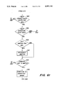
- FIGS. 6a-6h comprise a logic flow diagram of the algorithm executed by the microprocessor of FIG. 1.
- the intrusion detection system 10 includes an ultrasonic transducer XM1, such as an electrostatic ultrasonic transducer part No. 607281 manufactured by Polaroid Corp., coupled to a transceiver 11.
- the transducer XM1 directs an ultrasonic acoustic signal towards objects to be detected.
- the object or objects reflect an ultrasonic acoustic echo back to transducer XM1 with a time delay related to the relative distance between the object and the transducer.
- the transceiver 11 receives a transmit signal, T, with components at 45 and 55 kHz and a transmit mask or clamp signal Tc, both signals supplied by a microprocessor 12.
- the microprocessor may be a standard microprocessor with an integral analog-to-digital (A/D) converter, such as the MC 68HC11 manufactured by Motorola.
- the transceiver 11 provides the transmit signal to transducer XM1 and receives the echo or received signal, R, from transducer XM1 and provides it to a second order band pass filter 14 with a center frequency of 50 kHz.
- the band pass filter 14 also receives the transmit clamp or mask signal TC and provides a filtered receive signal Rf to an amplifier 16 with a gain of 25.
- the output of amplifier 16 is coupled to an envelope detector/amplifier 20.
- a rectified, amplified and filtered envelope signal E with gain of 125 is supplied to an A/D input of the microprocessor 12.
- the microprocessor 12 receives the amplified, filtered envelope receive signal, executes an algorithm and produces an alarm signal under certain conditions as hereinafter described in detail.
- the reader may refer to FIGS. 2-5 and the component examples set forth in the component tables.
- a resistor/capacitor network 22 is coupled to the mode, power, interrupt and A/D reference inputs of the microprocessor 12. Also, connected to the micro 12 is a timing crystal circuit 24 and a temperature compensating circuit 26 and a reset circuit 28.
- the micro 12 executes an algorithm which will now be described with reference to FIG. 6a-6h.
- the reader is referred to the exemplary assembly language computer program listing in the microfiche appendix.
- the algorithm begins with start, system setup and analog-to-digital converter (A/D) startup in steps 100-120.
- A/D analog-to-digital converter
- step 130 the A/D is read to determine whether this particular unit is a master or slave unit with other units if a plurality of these units are combined. This step can be dispensed with if this particular unit operates as a stand-alone unit.
- step 150 sets a starts-transmit timer and step 160 restarts the A/D.
- steps 170-230 operate to calculate and store an average A/D "base-line” or "zero"value (ZVAL) from a series, 16 for example, of consecutively read A/D values.
- ZVAL zero"value
- Step 240 gets a predetermined signature scan count value, SSCAN, 20 for example, which represents the number of separate echo signals which will be utilized or processed to generate in step 630 a signature data array which comprises the initial or reference echo signal "signature” or "image” to which data produced by later received echo signals will be compared in step 720.
- Step 250 initializes a signature amplitude threshold value, AMPTHS, and a non-signature amplitude threshold value, AMPTHN, below which the echo signals are ignored (see steps 600-620 and 690-710). These threshold values start out high and are gradually and incremental decreased to lower values.
- step 260 initializes a train count value and a pulse count value.
- the train count value represents the number, preferably 7 or 13, of pulse trains which make up each transmit signal.
- the pulse count value represents the number, preferably 8, of toggles of port A within each train. For sensing over shorter distances, 7 trains are used and for longer distances 13 trains are used.
- Steps 270-290 operate to cause step 285 turn on a Synch Pulse value or to cause step 295 to set a counter for the start of transmit time at the proper time depending upon whether this particular unit is a master or slave unit.
- Steps 300-340 (together with step 260) operate to periodically toggle (at step 300) the output of port A of the microprocessor to qenerate a transmit signal pulse.
- This transmit pulse train is applied to the transceiver 11 and causes the transducer XM1 to emit a burst of ultrasonic sound which hits any surfaces within a certain region, from which echoes are reflected back and are received by the transducer XM1, resulting in an amplified echo envelope signal being supplied to pin 49 and the A/D of microprocessor 12.
- step 350 turns on a transmit clamp signal Tc to which is applied the transceiver 11 to reduce "ringing" in the transceiver 11.
- step 360 turns off the Synch Pulse for purposes of synchronization of multiple units in connection with steps 270-290.
- a timer reference value, CTR (derived from a continuously running hardware timer counter internal to the microprocessor) is set in step 370 to represent a delay time of 1.5 milliseconds, for example, between the start of the transmit signal and the start of a detect period, and a scan counter value is zeroed in step 380 to represent the duration of a time period during which echo envelope signals will be processed.
- Step 390 causes the algorithm to pause until the delay time period has expired following the clamping of the transmit signal so that any ringing in the transceiver will have died down before any echo envelope signals are processed, whereupon the internal A/ D is restarted in step 410 to generate a binary DATA value representing the amplitude of the envelope echo signal at input terminal 49 of the microprocessor 12.
- a zero time timer reference value, CNTN is saved at step 420.
- step 430 a scan rate time reference value is set and step 440 causes the algorithm to wait until the scan rate timer reference value is reached so that the echo signal at the A/D input of the micro 12 will be sampled at a desired rate of every 140 microseconds, for example. Then step 450 saves the old CNTN value from step 420 as a current timer reference value, CNTC, for use in connection with a variable gain feature described later herein with reference to steps 540 and 550.
- step 470 the current value at micro input 49 is sampled, analog-to-digitally converted and stored as a data value.
- the A/D is restarted so that its registers will be cleared for later conversion of a new DATA value and in step 490 the converted data value is stored as a binary ADC value which represents the current amplitude of the echo envelope signal.
- step 500 the present timer count, from beginning of transmit, is saved as a CNTN value.
- step 510 the ZVAL value from step 230 is subtracted from ADC to obtain a DATA value.
- Steps 520 and 530 then operate to ensure that only non-negative DATA values are utilized later in the algorithm.
- Steps 540 and 550 operate to determine a gain value, GAIN, from the most significant bit of the CNTC value.
- GAIN the gain value
- the gain value, GAIN will vary as a function of time from a low value (compensating for strong amplitude early echoes from near surfaces) to a high value (compensating for lower amplitude later echoes) from distant surfaces.
- step 560 and 570 the ADC value is multiplied by the GAIN value and this multiplied value is stored as ADC.
- step 580 the sample count value, CNTS, is compared to a minimum value representing a near distance, such as approximately two feet, so that objects intruding at a distance of closer than this distance will be ignored. If CNTS is less than this minimum value, then the algorithm is directed to step 640. Otherwise, the algorithm proceeds to step 590 which tests the scan count timer value, SCCAN, to determine whether or not the algorithm has completed processing of the initial twenty echo signals to determine the data "signature". If not, the algorithm proceeds to step 600, otherwise to step 690.
- SCCAN scan count timer value
- Steps 600 and 610 operate to gradually and stepwise reduce the amplitude threshold value, AMPTHS, from an initial high value (representing about 1.14 volts) down to a minimum value (representing about 0.38 volts). This compensates for attenuation from further objects.
- Step 620 compares the data value (ADC) from step 570 with the AMPTHS value and if ADC is greater than or equal to AMPTHS, then a flag or a binary one is stored in a corresponding position in a 360 bit signature data array by step 630.
- This signature data array initially contains all zeros, but steps 620 and 630 operate to replace a zero with a one whenever the data value ADC exceeds the AMPTHS value during processing of the first twenty echo signals.
- step 640 the algorithm proceeds to step 640 without changing the corresponding bit in the signature data array.
- a flag one is entered into the signature data array, that flag remains in that location of the data array until the system is reset.
- the first twenty echo signals Is cumulatively processed and a 360 bit data array of ones zeroes will be generated to represent a cumulative "signature" of the first twenty echo signals.
- step 590 will direct the algorithm to steps 690 and 700 which operate to gradually and stepwise reduce the non-signature amplitude threshold value AMPTHN from a high value (representing approximately 1.5 volts) down to a minimum value (representing approximately 0.29 volts). Then step 710 compares the most recent ADC data value to AMPTHN and directs the algorithm to step 640 and ignores ADC values which are less than AMPTHN. Otherwise, step 710 directs the algorithm to step 720 which tests the signature data array.
- steps 690 and 700 which operate to gradually and stepwise reduce the non-signature amplitude threshold value AMPTHN from a high value (representing approximately 1.5 volts) down to a minimum value (representing approximately 0.29 volts). Then step 710 compares the most recent ADC data value to AMPTHN and directs the algorithm to step 640 and ignores ADC values which are less than AMPTHN. Otherwise, step 710 directs the algorithm to step 720 which tests the signature data array.
- step 720 directs the algorithm to step 640. If a zero resides in the corresponding position in the signature data array, then it means that the present echo signal differs from the signature and step 720 will direct the algorithm to steps 730-750 which cause an alarm signal to be generated at port A for a certain duration. Then step 760 sets a timer for the timing of the next transmit signal so that the transmit signals are generated at a 100 millisecond repetition rate and directs the algorithm to step 655.
- step 640 increments and tests a timer or counter for a maximum sample count value which can be chosen to determine the maximum object distance from which echoes can be processed by this system. If this maximum value has not yet been reached then step 645 stores the current sample count value, CTS, and the algorithm is directed back to step 430 for processing of the next sample of the echo signal. If this maximum value has been reached, then step 640 directs the algorithm to step 650 which sets the timer for the timing of the next transmit signal so that transmit signal will be generated every 100 milliseconds.
- Step 655 sets this new transmit time value into the counter value, CTR. Then steps 660 and 670 operate (together with steps 590) to test and decrement the signature scan count value so that only the desired number (20 for example) of echo signals will be processed to determine the initial echo signal signature data array to which later received echo signals are compared (in step 710). After step 760 the algorithm returns to step 250 whereupon a new transmit signal is generated and the algorithm is executed again.
Abstract
A microprocessor-based ultrasonic intrusion detection system includes an initialization mode wherein a plurality of echoes are cumulatively processed to produce a reference or signature data set representing the area to be monitored without intruding objects. Later received echoes are compared to this signature so that an intruding object will cause generation of an alarm signal. Time varying thresholds are utilized to compensate for attenuation caused by increased distance.
Description
This application includes a microfiche appendix including one microfiche and 14 frames.
The present invention relates to an ultrasonic system for detecting intrusion of objects or persons into a monitored area.
Ultrasonic intrusion detection systems are known wherein reflected wave patterns are compared to reference patterns such as described in U.S. Pat. No. 4,499,564, issued on 12 Feb. 1985 to Sirai. In this system, the reference pattern is based upon the statistical mean values of a plurality of reflected waves. Then reflected wave patterns are statistically compared to the reference pattern and an alarm is energized when a sampling point of the reflected wave differs from a corresponding point of the reference pattern by more than a standard deviation.
A microprocessor-based system is described in U.S. Pat. No. 4,800,540, issued 24 Jan. 1989 to Annala. In this system, 100 bursts are processed and a reference table is generated which includes echo or no-echo flag values only for sample time points which consistently yield indications of echoes or non-echoes, respectively. Then, in a detection mode, portions of the reference table which include transitions in adjacent locations and the corresponding sampled signal locations are ignored.
Such systems are complex and are intended to filter out background noise and to reduce erroneous alarm indications. However, when such a system is to be adapted for use on a vehicle or on a piece of heavy machinery, then safety becomes of primary importance. For purposes of safety, it is preferable to accept some erroneous indications in the interest of insuring that legitimate intrusions produce an alarm signal. Accordingly, a relatively simple intrusion detection system which enhances safety is desired.
These and other objects are achieved by the present invention which include an ultrasonic transducer, a transceiver and a microprocessor-based signal processing unit. In a-initialization mode, a plurality of echoes are cumulatively processed to produce a signature or reference set of data. In the detection mode, if any portion of an echo signal exceeds a signature threshold, then an alarm signal is generated to indicate intrusion of an object into the area being monitored.
FIG. 1 is a simplified schematic block diagram of an ultrasonic intrusion detection system according to the present invention.
FIG. 2 is a detailed circuit diagram of the transceiver of FIG. 1.
FIG. 3 is a detailed circuit diagram of the band-pass filter of FIG. 1,
FIG. 4 is a detailed circuit diagram of the amplifier and envelope and detector/amplifier of FIG. 1.
FIG. 5 is a detailed circuit diagram of the portions of FIG. 1 including the microprocessor.
FIGS. 6a-6h comprise a logic flow diagram of the algorithm executed by the microprocessor of FIG. 1.
Referring to FIG. 1, the intrusion detection system 10 includes an ultrasonic transducer XM1, such as an electrostatic ultrasonic transducer part No. 607281 manufactured by Polaroid Corp., coupled to a transceiver 11. The transducer XM1 directs an ultrasonic acoustic signal towards objects to be detected. The object or objects reflect an ultrasonic acoustic echo back to transducer XM1 with a time delay related to the relative distance between the object and the transducer. The transceiver 11 receives a transmit signal, T, with components at 45 and 55 kHz and a transmit mask or clamp signal Tc, both signals supplied by a microprocessor 12. The microprocessor may be a standard microprocessor with an integral analog-to-digital (A/D) converter, such as the MC 68HC11 manufactured by Motorola. The transceiver 11 provides the transmit signal to transducer XM1 and receives the echo or received signal, R, from transducer XM1 and provides it to a second order band pass filter 14 with a center frequency of 50 kHz.
The band pass filter 14 also receives the transmit clamp or mask signal TC and provides a filtered receive signal Rf to an amplifier 16 with a gain of 25. The output of amplifier 16 is coupled to an envelope detector/amplifier 20. Thus, a rectified, amplified and filtered envelope signal E with gain of 125 is supplied to an A/D input of the microprocessor 12.
The microprocessor 12 receives the amplified, filtered envelope receive signal, executes an algorithm and produces an alarm signal under certain conditions as hereinafter described in detail. For more detailed information concerning the circuit shown in FIG. 1, the reader may refer to FIGS. 2-5 and the component examples set forth in the component tables.
Referring to FIG. 5, a resistor/capacitor network 22 is coupled to the mode, power, interrupt and A/D reference inputs of the microprocessor 12. Also, connected to the micro 12 is a timing crystal circuit 24 and a temperature compensating circuit 26 and a reset circuit 28.
The micro 12 executes an algorithm which will now be described with reference to FIG. 6a-6h. For further details concerning the algorithm, the reader is referred to the exemplary assembly language computer program listing in the microfiche appendix.
The algorithm begins with start, system setup and analog-to-digital converter (A/D) startup in steps 100-120. In step 130, the A/D is read to determine whether this particular unit is a master or slave unit with other units if a plurality of these units are combined. This step can be dispensed with if this particular unit operates as a stand-alone unit. Then step 150 sets a starts-transmit timer and step 160 restarts the A/D. Then steps 170-230 operate to calculate and store an average A/D "base-line" or "zero"value (ZVAL) from a series, 16 for example, of consecutively read A/D values.
Then step 260 initializes a train count value and a pulse count value. The train count value represents the number, preferably 7 or 13, of pulse trains which make up each transmit signal. The pulse count value represents the number, preferably 8, of toggles of port A within each train. For sensing over shorter distances, 7 trains are used and for longer distances 13 trains are used. Steps 270-290 operate to cause step 285 turn on a Synch Pulse value or to cause step 295 to set a counter for the start of transmit time at the proper time depending upon whether this particular unit is a master or slave unit.
Steps 300-340 (together with step 260) operate to periodically toggle (at step 300) the output of port A of the microprocessor to qenerate a transmit signal pulse. This transmit pulse train is applied to the transceiver 11 and causes the transducer XM1 to emit a burst of ultrasonic sound which hits any surfaces within a certain region, from which echoes are reflected back and are received by the transducer XM1, resulting in an amplified echo envelope signal being supplied to pin 49 and the A/D of microprocessor 12.
Following generation of this transmit pulse train step 350 turns on a transmit clamp signal Tc to which is applied the transceiver 11 to reduce "ringing" in the transceiver 11. Then step 360 turns off the Synch Pulse for purposes of synchronization of multiple units in connection with steps 270-290.
A timer reference value, CTR, (derived from a continuously running hardware timer counter internal to the microprocessor) is set in step 370 to represent a delay time of 1.5 milliseconds, for example, between the start of the transmit signal and the start of a detect period, and a scan counter value is zeroed in step 380 to represent the duration of a time period during which echo envelope signals will be processed. Step 390 causes the algorithm to pause until the delay time period has expired following the clamping of the transmit signal so that any ringing in the transceiver will have died down before any echo envelope signals are processed, whereupon the internal A/ D is restarted in step 410 to generate a binary DATA value representing the amplitude of the envelope echo signal at input terminal 49 of the microprocessor 12. A zero time timer reference value, CNTN, is saved at step 420.
In step 430 a scan rate time reference value is set and step 440 causes the algorithm to wait until the scan rate timer reference value is reached so that the echo signal at the A/D input of the micro 12 will be sampled at a desired rate of every 140 microseconds, for example. Then step 450 saves the old CNTN value from step 420 as a current timer reference value, CNTC, for use in connection with a variable gain feature described later herein with reference to steps 540 and 550.
Then in step 470 the current value at micro input 49 is sampled, analog-to-digitally converted and stored as a data value. Then, in step 480 the A/D is restarted so that its registers will be cleared for later conversion of a new DATA value and in step 490 the converted data value is stored as a binary ADC value which represents the current amplitude of the echo envelope signal. Then, in step 500, the present timer count, from beginning of transmit, is saved as a CNTN value.
In step 510 the ZVAL value from step 230 is subtracted from ADC to obtain a DATA value. Steps 520 and 530 then operate to ensure that only non-negative DATA values are utilized later in the algorithm.
In steps 560 and 570 the ADC value is multiplied by the GAIN value and this multiplied value is stored as ADC. In step 580 the sample count value, CNTS, is compared to a minimum value representing a near distance, such as approximately two feet, so that objects intruding at a distance of closer than this distance will be ignored. If CNTS is less than this minimum value, then the algorithm is directed to step 640. Otherwise, the algorithm proceeds to step 590 which tests the scan count timer value, SCCAN, to determine whether or not the algorithm has completed processing of the initial twenty echo signals to determine the data "signature". If not, the algorithm proceeds to step 600, otherwise to step 690.
Referring back to FIG. 6f and step 590, if the signature data array has been completed (20 echoes processed) then step 590 will direct the algorithm to steps 690 and 700 which operate to gradually and stepwise reduce the non-signature amplitude threshold value AMPTHN from a high value (representing approximately 1.5 volts) down to a minimum value (representing approximately 0.29 volts). Then step 710 compares the most recent ADC data value to AMPTHN and directs the algorithm to step 640 and ignores ADC values which are less than AMPTHN. Otherwise, step 710 directs the algorithm to step 720 which tests the signature data array. If a one is in the corresponding location in the signature data array, then it means that the present echo signal matches the signature and step 720 directs the algorithm to step 640. If a zero resides in the corresponding position in the signature data array, then it means that the present echo signal differs from the signature and step 720 will direct the algorithm to steps 730-750 which cause an alarm signal to be generated at port A for a certain duration. Then step 760 sets a timer for the timing of the next transmit signal so that the transmit signals are generated at a 100 millisecond repetition rate and directs the algorithm to step 655.
Referring now to FIG. 6h, step 640 increments and tests a timer or counter for a maximum sample count value which can be chosen to determine the maximum object distance from which echoes can be processed by this system. If this maximum value has not yet been reached then step 645 stores the current sample count value, CTS, and the algorithm is directed back to step 430 for processing of the next sample of the echo signal. If this maximum value has been reached, then step 640 directs the algorithm to step 650 which sets the timer for the timing of the next transmit signal so that transmit signal will be generated every 100 milliseconds.
Step 655 sets this new transmit time value into the counter value, CTR. Then steps 660 and 670 operate (together with steps 590) to test and decrement the signature scan count value so that only the desired number (20 for example) of echo signals will be processed to determine the initial echo signal signature data array to which later received echo signals are compared (in step 710). After step 760 the algorithm returns to step 250 whereupon a new transmit signal is generated and the algorithm is executed again.
______________________________________
Component Table
Schematic
Designation   Description
______________________________________
T1            Transformer 40:1, Poloroid No. 605541
X1            Crystal, 8.0 MHZ
U1, U2        IC, Quad OP-AMP, MC 33074
U6            IC, Reset Circuit, MC33064P-5
Q1            Transistor, MMBTA42, SMO
Q2            Transistor, Darlington,
              MMBTA14, SMO
Q6            Transistor, FET 2N4393
D1, D2        Diode, 1N4006
D3 + 4, D5 + 6,
              Diode Pair, SMO MMB04000
D7 + 8
D20           Diode, 1N914
C36           Capacitor, Electrolytic,
              220 μF, 50 VDC
C2            Capacitor, Tantalum, 10 μF,
              10%, 5 VDC
C1            Capacitor, Polyester, 0.022
              μF, 10%, 400 VDC
C3, C4, C6,   Capacitor, Ceramic Chip, 0.1 μF
C12, C13, C21,
              10%, 50 VDC, X7R, SMO
C22, C23
C7, C8        Capacitor, Ceramic Chip,
              .001 μF, 10%, 50 VDC, X7R, SMO
C10           Capacitor, Ceramic Chip,
              470 pF, 5%, 50 VDC, C06, SMO
C11           Capacitor, Ceramic Chip, 390 pF,
              5%, 100 VDC, C06, SMO
C5            Capacitor, Ceramic Chip,
              100 pF, 5%, 100 VDC, C06, SMO
C33, C34      Capacitor, Ceramic Chip, 27 pf,
              0%, 200 VDC C06, SMO
C35           Capacitor, .01 μf
R2, R6        Resistor, SMO, 7.5 (Ohms), 5%, 1/4W
R54           Resistor, SMO, 402, 1%, 1/8W
R11           Resistor, SMO, 787, 1%, 1/8 W
R52           Resistor, SMO, 1.33K, 1%, 1/8 W
R1, R3, R5,   Resistor, SMO, 2.0K, 5%, 1/8 W
R26
R25           Resistor, SMO, 2.10K, 1%, 1/8 W
R18           Resistor, SMO, 2.55K, 1%, 1/8 W
R78           Resistor, SMO, 2.61K, 1%, 1/8 W
R10           Resistor, SMO, 3.32K, 1, 1/8 W
R53           Resistor, SMO, 3.24K, 1%, 1/8 W
R17           Resistor, SMO, 5.11K, 1%, 1/8 W
R22           Resistor, SMO, 5.23K, 1%, 1/8 W
R8, R21, R79  Resistor, SMO, 10K, 5%, 1/8 W
R16           Resistor, SMO, 11K, 5%, 1/8 W
R1            Resistor, SMO, 16K, 5%, 1/8 W
R4, R7, R13,  Resistor, SMO, 20K, 5%, 1/8 W
R14, R15
R19, R20      Resistor, SMO, 40.2K, 1%, 1/8 W
R23, R24, R27 Resistor, SMO, 51.1K, 1%, 1/8 W
R9            Resistor, SMO, 100K, 5%, 1/8 W
R31a, R32a    Resistor, SMO, 400K, 5%. 1/8 W
R77           Resisto, SMO, 10H, 5%, 1/8 W
RT1           Thermister, 10K, 250C
______________________________________
A portion of the disclosure of this patent document contains material which is subject to a claim of copyright protection. The copyright owner has no objection to the facsimile reproduction by anyone of the patent document or the patent disclosure, as it appears in the Patent and Trademark Office patent file or records, but otherwise reserves all other rights whatsoever.
While the invention has been described in conjunction with a specific embodiment, it is to be understood that many alternatives, modifications and variations will be apparent to those skilled in the art in light of the aforegoing description.
Accordingly, this invention is intended to embrace all such alternatives, modifications and variations which fall within the spirit and scope of the appended claims.
Claims (5)
1. A system for detecting intrusions into an area to be monitored, the system comprising:
means for periodically directing a transmit signal into the area so that a plurality of echo signals will be reflected from objects intruding into the area;
means for receiving echo signals reflected by an object or objects in the area;
means for generating a signature data array derived by cumulatively processing an initial set of signature echo signals, the means for generating a signature data array comprising means for generating and storing an initial signature data array having a plurality of data bits corresponding to segments of the echo signals, and means for comparing each signature echo signal segment to a signature threshold value and for replacing a corresponding initial data bit value with a flag value if said segment exceeds the threshold value; and
means for comparing non-signature data representing non-signature echoes received after reception of said signature echo signals to the signature data array and for generating an alarm signal when the non-signature data differs from signature data.
2. The invention of claim 1, further comprising:
means for reducing the signature threshold value as a function of time.
3. A system for detecting intrusions into an area to be monitored, the system comprising:
means for periodically directing a transmit signal into the area so that a plurality of echo signals will be reflected from objects intruding into the area;
means for receiving echo signals reflected by an object or objects in the area;
means for generating a signature data array derived by cumulatively processing an initial set of signature echo signals;
means for comparing non-signature data representing non-signature echoes received after reception of said signature echo signals to the signature data array and for generating an alarm signal when the non-signature data differs from signature data; and
means for comparing non-signature echo signal segments to a non-signature threshold value and ignoring segments which do not exceed said non-signature threshold.
4. The invention of claim 3, further comprising:
means for comparing each signature echo signal segment to a signature threshold value and for replacing a corresponding initial data bit value with a flag value if said segment exceeds the threshold value; and
means for generating an alarm signal each time a non-signature echo signal segment exceeds the non-signature threshold value and no flag value is present in an corresponding portion of the signature data array.
5. The invention of claim 3, further comprising: means for reducing the non-signature threshold value as a function of time.
Priority Applications (5)
| Application Number | Priority Date | Filing Date | Title |
|---|---|---|---|
| US07/443,684 US4991146A (en) | 1989-11-30 | 1989-11-30 | Intrusion detection system |
| CA002029089A CA2029089C (en) | 1989-11-30 | 1990-10-31 | Intrusion detection system |
| JP2328829A JPH03186783A (en) | 1989-11-30 | 1990-11-28 | Entry detection system |
| NO90905160A NO905160L (en) | 1989-11-30 | 1990-11-29 | SYSTEM FOR AA DETECTED INTRODUCTION. |
| EP19900122806 EP0430226A3 (en) | 1989-11-30 | 1990-11-29 | Method and device for detecting approaching objects |
Applications Claiming Priority (1)
| Application Number | Priority Date | Filing Date | Title |
|---|---|---|---|
| US07/443,684 US4991146A (en) | 1989-11-30 | 1989-11-30 | Intrusion detection system |
Publications (1)
| Publication Number | Publication Date |
|---|---|
| US4991146A true US4991146A (en) | 1991-02-05 |
Family
ID=23761794
Family Applications (1)
| Application Number | Title | Priority Date | Filing Date |
|---|---|---|---|
| US07/443,684 Expired - Fee Related US4991146A (en) | 1989-11-30 | 1989-11-30 | Intrusion detection system |
Country Status (5)
| Country | Link |
|---|---|
| US (1) | US4991146A (en) |
| EP (1) | EP0430226A3 (en) |
| JP (1) | JPH03186783A (en) |
| CA (1) | CA2029089C (en) |
| NO (1) | NO905160L (en) |
Cited By (39)
| Publication number | Priority date | Publication date | Assignee | Title |
|---|---|---|---|---|
| US5067115A (en) * | 1989-11-06 | 1991-11-19 | Mitsubishi Denki K.K. | Ultrasonic obstacle sensor |
| EP0508765A2 (en) * | 1991-04-09 | 1992-10-14 | Peek Traffic Limited | Improvements in vehicle detection systems |
| EP0568518A1 (en) * | 1992-04-29 | 1993-11-03 | Icoms Sprl | Detection method and system |
| EP0654768A1 (en) * | 1992-05-26 | 1995-05-24 | Valeo Electronique | Alarm system and method by analysis of the signal of a sensor |
| GB2299405A (en) * | 1995-03-29 | 1996-10-02 | Advanced Monitors | Ultrasonic monitor |
| GB2326237A (en) * | 1997-06-12 | 1998-12-16 | Visonic Ltd | Ultrasound intrusion detector |
| EP0909960A2 (en) * | 1997-09-16 | 1999-04-21 | f+g megamos Sicherheitselektronik GmbH | Ultrasound monitoring device to monitor the interior of a motor vehicle |
| US6114956A (en) * | 1992-06-25 | 2000-09-05 | Belgian Electronic Research S.A. | Device and method for sensing and protection of persons and objects |
| US20030033542A1 (en) * | 2001-06-11 | 2003-02-13 | Mcnc | Intrusion tolerant communication networks and associated methods |
| US6529130B2 (en) * | 2001-02-16 | 2003-03-04 | General Phosphorix Llc | System for detecting intruders |
| US6710705B1 (en) * | 2001-04-26 | 2004-03-23 | Tim Simon, Inc. | Method and apparatus for pest deterrence |
| US20060023709A1 (en) * | 2004-08-02 | 2006-02-02 | Hall Michael L | Inline intrusion detection using a single physical port |
| US20060161983A1 (en) * | 2005-01-20 | 2006-07-20 | Cothrell Scott A | Inline intrusion detection |
| US20070016786A1 (en) * | 2005-07-13 | 2007-01-18 | Lenovo Pte Ltd. | System and method for ISO image update and ISO image deconstruction into modular components |
| US20080169966A1 (en) * | 2006-08-09 | 2008-07-17 | Fujitsu Ten Limited | On-vehicle radar device |
| US20080278355A1 (en) * | 2007-05-08 | 2008-11-13 | Moore J Douglas | Intrusion detection using a capacitance sensitive touchpad |
| US7535351B2 (en) | 2006-07-24 | 2009-05-19 | Welles Reymond | Acoustic intrusion detection system |
| US7562389B1 (en) | 2004-07-30 | 2009-07-14 | Cisco Technology, Inc. | Method and system for network security |
| US20090276239A1 (en) * | 2008-04-30 | 2009-11-05 | Ecolab Inc. | Validated healthcare cleaning and sanitizing practices |
| US20100274640A1 (en) * | 2009-04-24 | 2010-10-28 | Ecolab Usa Inc. | Management of cleaning processes via monitoring of chemical product usage |
| CN101441496B (en) * | 2007-11-22 | 2010-12-08 | 英业达股份有限公司 | Portable computer and theft-proof method thereof |
| US20100315243A1 (en) * | 2009-06-12 | 2010-12-16 | Ecolab Usa Inc. | Hand hygiene compliance monitoring |
| US20120140597A1 (en) * | 2010-12-07 | 2012-06-07 | Gwangju Institute Of Science And Technology | Security monitoring system using beamforming acoustic imaging and method using the same |
| US20130077442A1 (en) * | 2011-09-23 | 2013-03-28 | Stephen Hersey | Ultrasonic motion detection |
| US20130235700A1 (en) * | 2012-03-09 | 2013-09-12 | Semiconductor Components Industries, Llc | Semiconductor device and method of forming same for acoustic sensing of close proximity objects |
| US8639527B2 (en) | 2008-04-30 | 2014-01-28 | Ecolab Usa Inc. | Validated healthcare cleaning and sanitizing practices |
| CN103675820A (en) * | 2012-09-24 | 2014-03-26 | 和硕联合科技股份有限公司 | Object detection method and object detection device using ultrasonic waves |
| EP2715694A1 (en) * | 2011-06-03 | 2014-04-09 | Elsi Technologies Oy | Method and system for observation |
| US20150003205A1 (en) * | 2012-01-31 | 2015-01-01 | Panasonic Corporation | Ultrasound sensor |
| US9151855B2 (en) | 2011-03-17 | 2015-10-06 | Ardmore Associates, LLC | Barrier detection system and method |
| US9283677B2 (en) | 2012-04-05 | 2016-03-15 | Rethink Robotics, Inc. | Visual indication of target tracking |
| WO2016089518A1 (en) * | 2014-12-02 | 2016-06-09 | Qualcomm Incorporated | Method and apparatus for performing ultrasonic presence detection |
| JP2016193020A (en) * | 2015-03-31 | 2016-11-17 | セコム株式会社 | Ultrasonic sensor |
| US9507968B2 (en) | 2013-03-15 | 2016-11-29 | Cirque Corporation | Flying sense electrodes for creating a secure cage for integrated circuits and pathways |
| US9824569B2 (en) | 2011-01-28 | 2017-11-21 | Ecolab Usa Inc. | Wireless communication for dispenser beacons |
| US10529219B2 (en) | 2017-11-10 | 2020-01-07 | Ecolab Usa Inc. | Hand hygiene compliance monitoring |
| USRE48951E1 (en) | 2015-08-05 | 2022-03-01 | Ecolab Usa Inc. | Hand hygiene compliance monitoring |
| US11272815B2 (en) | 2017-03-07 | 2022-03-15 | Ecolab Usa Inc. | Monitoring modules for hand hygiene dispensers |
| US11284333B2 (en) | 2018-12-20 | 2022-03-22 | Ecolab Usa Inc. | Adaptive route, bi-directional network communication |
Families Citing this family (1)
| Publication number | Priority date | Publication date | Assignee | Title |
|---|---|---|---|---|
| CA2201080C (en) * | 1996-03-27 | 2000-01-25 | Her Majesty The Queen, In Right Of Canada, As Represented By The Ministe R Of Industry | Ultrasonic detection system for safety of vehicle passengers |
Citations (12)
| Publication number | Priority date | Publication date | Assignee | Title |
|---|---|---|---|---|
| US4197528A (en) * | 1977-04-22 | 1980-04-08 | Eurolec Group Limited | Movement-detecting processing circuit for an ultrasonic detection system |
| US4229811A (en) * | 1978-11-09 | 1980-10-21 | General Electric Company | Intrusion detection method and apparatus |
| US4290126A (en) * | 1979-11-09 | 1981-09-15 | General Electric Company | Ultrasonic intrusion alarm system |
| US4382291A (en) * | 1980-10-17 | 1983-05-03 | Secom Co., Ltd. | Surveillance system in which a reflected signal pattern is compared to a reference pattern |
| US4499564A (en) * | 1980-08-20 | 1985-02-12 | Secom Co., Ltd. | Pattern comparison ultrasonic surveillance system with noise suppression |
| US4512000A (en) * | 1980-12-23 | 1985-04-16 | Tokyo Shibaura Denki Kabushiki Kaisha | Object detector which compares returned signals from successive transmissions |
| US4542489A (en) * | 1982-05-18 | 1985-09-17 | Aisin Seiki Kabushiki Kaisha | Object detecting system of reflection type |
| US4608674A (en) * | 1982-08-06 | 1986-08-26 | American District Telegraph Company | Constant range ultrasonic motion detector |
| US4628496A (en) * | 1984-07-27 | 1986-12-09 | Von Duprin, Inc. | Ultrasonic sensing and monitoring systems |
| US4639902A (en) * | 1985-06-24 | 1987-01-27 | The United States Of America As Represented By The Secretary Of The Navy | Near ultrasonic pattern comparison intrusion detector |
| US4779240A (en) * | 1985-04-29 | 1988-10-18 | Xecutek Corporation | Ultrasonic sensor system |
| US4800540A (en) * | 1986-12-04 | 1989-01-24 | The United States Of America As Represented By The United States Department Of Energy | Discriminating ultrasonic proximity detection system |
Family Cites Families (2)
| Publication number | Priority date | Publication date | Assignee | Title |
|---|---|---|---|---|
| GB2050022A (en) * | 1979-05-02 | 1980-12-31 | Moser M | Intruder Alarm |
| GB2137749A (en) * | 1983-04-07 | 1984-10-10 | Healey Meters Limited | Intruder Detection System |
-
1989
- 1989-11-30 US US07/443,684 patent/US4991146A/en not_active Expired - Fee Related
-
1990
- 1990-10-31 CA CA002029089A patent/CA2029089C/en not_active Expired - Fee Related
- 1990-11-28 JP JP2328829A patent/JPH03186783A/en active Pending
- 1990-11-29 EP EP19900122806 patent/EP0430226A3/en not_active Withdrawn
- 1990-11-29 NO NO90905160A patent/NO905160L/en unknown
Patent Citations (12)
| Publication number | Priority date | Publication date | Assignee | Title |
|---|---|---|---|---|
| US4197528A (en) * | 1977-04-22 | 1980-04-08 | Eurolec Group Limited | Movement-detecting processing circuit for an ultrasonic detection system |
| US4229811A (en) * | 1978-11-09 | 1980-10-21 | General Electric Company | Intrusion detection method and apparatus |
| US4290126A (en) * | 1979-11-09 | 1981-09-15 | General Electric Company | Ultrasonic intrusion alarm system |
| US4499564A (en) * | 1980-08-20 | 1985-02-12 | Secom Co., Ltd. | Pattern comparison ultrasonic surveillance system with noise suppression |
| US4382291A (en) * | 1980-10-17 | 1983-05-03 | Secom Co., Ltd. | Surveillance system in which a reflected signal pattern is compared to a reference pattern |
| US4512000A (en) * | 1980-12-23 | 1985-04-16 | Tokyo Shibaura Denki Kabushiki Kaisha | Object detector which compares returned signals from successive transmissions |
| US4542489A (en) * | 1982-05-18 | 1985-09-17 | Aisin Seiki Kabushiki Kaisha | Object detecting system of reflection type |
| US4608674A (en) * | 1982-08-06 | 1986-08-26 | American District Telegraph Company | Constant range ultrasonic motion detector |
| US4628496A (en) * | 1984-07-27 | 1986-12-09 | Von Duprin, Inc. | Ultrasonic sensing and monitoring systems |
| US4779240A (en) * | 1985-04-29 | 1988-10-18 | Xecutek Corporation | Ultrasonic sensor system |
| US4639902A (en) * | 1985-06-24 | 1987-01-27 | The United States Of America As Represented By The Secretary Of The Navy | Near ultrasonic pattern comparison intrusion detector |
| US4800540A (en) * | 1986-12-04 | 1989-01-24 | The United States Of America As Represented By The United States Department Of Energy | Discriminating ultrasonic proximity detection system |
Non-Patent Citations (11)
| Title |
|---|
| BATS Inc., "Blindspot Warning System Model BS1000", 2 pages. |
| BATS Inc., Blindspot Warning System Model BS1000 , 2 pages. * |
| International Automotive Products, "The Ultrasonic Tattletail", 4 pages. |
| International Automotive Products, The Ultrasonic Tattletail , 4 pages. * |
| Massa Products Corporation, "Model E--200 Ultrasonic Ranging Module", 7 pages, 1988. |
| Massa Products Corporation, Model E 200 Ultrasonic Ranging Module , 7 pages, 1988. * |
| Opcon Inc., "UC60--LN1A Ultrasonic Sensor--Installation Instructions", pp. 1-11, 1988. |
| Opcon Inc., UC60 LN1A Ultrasonic Sensor Installation Instructions , pp. 1 11, 1988. * |
| Opcon, Inc., "Sonic Sensors--Price List 600", 4 pages, 1988. |
| Opcon, Inc., Sonic Sensors Price List 600 , 4 pages, 1988. * |
| Weigand, Montageanlleitung Range Master . . . , 7 pages, 1988. * |
Cited By (71)
| Publication number | Priority date | Publication date | Assignee | Title |
|---|---|---|---|---|
| US5067115A (en) * | 1989-11-06 | 1991-11-19 | Mitsubishi Denki K.K. | Ultrasonic obstacle sensor |
| EP0508765A2 (en) * | 1991-04-09 | 1992-10-14 | Peek Traffic Limited | Improvements in vehicle detection systems |
| EP0508765A3 (en) * | 1991-04-09 | 1993-01-20 | Peek Traffic Limited | Improvements in vehicle detection systems |
| US5339081A (en) * | 1991-04-09 | 1994-08-16 | Peek Traffic Limited | Vehicle detection systems |
| EP0568518A1 (en) * | 1992-04-29 | 1993-11-03 | Icoms Sprl | Detection method and system |
| BE1005734A5 (en) * | 1992-04-29 | 1994-01-11 | Icoms Sprl | Method and detection system. |
| US5424745A (en) * | 1992-04-29 | 1995-06-13 | Ccoms Sprl | Detection method and system |
| EP0654768A1 (en) * | 1992-05-26 | 1995-05-24 | Valeo Electronique | Alarm system and method by analysis of the signal of a sensor |
| US6114956A (en) * | 1992-06-25 | 2000-09-05 | Belgian Electronic Research S.A. | Device and method for sensing and protection of persons and objects |
| GB2299405A (en) * | 1995-03-29 | 1996-10-02 | Advanced Monitors | Ultrasonic monitor |
| US5973996A (en) * | 1997-06-12 | 1999-10-26 | Visonic Ltd. | Ultrasound intrusion detector |
| GB2326237A (en) * | 1997-06-12 | 1998-12-16 | Visonic Ltd | Ultrasound intrusion detector |
| GB2326237B (en) * | 1997-06-12 | 2001-07-25 | Visonic Ltd | Ultrasound intrusion detector |
| EP0909960A2 (en) * | 1997-09-16 | 1999-04-21 | f+g megamos Sicherheitselektronik GmbH | Ultrasound monitoring device to monitor the interior of a motor vehicle |
| EP0909960A3 (en) * | 1997-09-16 | 1999-05-19 | f+g megamos Sicherheitselektronik GmbH | Ultrasound monitoring device to monitor the interior of a motor vehicle |
| US6529130B2 (en) * | 2001-02-16 | 2003-03-04 | General Phosphorix Llc | System for detecting intruders |
| US6710705B1 (en) * | 2001-04-26 | 2004-03-23 | Tim Simon, Inc. | Method and apparatus for pest deterrence |
| US20030033542A1 (en) * | 2001-06-11 | 2003-02-13 | Mcnc | Intrusion tolerant communication networks and associated methods |
| US7350234B2 (en) * | 2001-06-11 | 2008-03-25 | Research Triangle Institute | Intrusion tolerant communication networks and associated methods |
| US7562389B1 (en) | 2004-07-30 | 2009-07-14 | Cisco Technology, Inc. | Method and system for network security |
| US20060023709A1 (en) * | 2004-08-02 | 2006-02-02 | Hall Michael L | Inline intrusion detection using a single physical port |
| US7555774B2 (en) | 2004-08-02 | 2009-06-30 | Cisco Technology, Inc. | Inline intrusion detection using a single physical port |
| US20060161983A1 (en) * | 2005-01-20 | 2006-07-20 | Cothrell Scott A | Inline intrusion detection |
| US9009830B2 (en) | 2005-01-20 | 2015-04-14 | Cisco Technology, Inc. | Inline intrusion detection |
| US7725938B2 (en) | 2005-01-20 | 2010-05-25 | Cisco Technology, Inc. | Inline intrusion detection |
| US7600127B2 (en) * | 2005-07-13 | 2009-10-06 | Lenovo Singapore Pte. Ltd | System and method for ISO image update and ISO image deconstruction into modular components |
| US20070016786A1 (en) * | 2005-07-13 | 2007-01-18 | Lenovo Pte Ltd. | System and method for ISO image update and ISO image deconstruction into modular components |
| US7535351B2 (en) | 2006-07-24 | 2009-05-19 | Welles Reymond | Acoustic intrusion detection system |
| US7504989B2 (en) * | 2006-08-09 | 2009-03-17 | Fujitsu Ten Limited | On-vehicle radar device |
| US20080169966A1 (en) * | 2006-08-09 | 2008-07-17 | Fujitsu Ten Limited | On-vehicle radar device |
| US9507466B2 (en) * | 2007-05-08 | 2016-11-29 | Cirque Corporation | Intrusion detection using a capacitance sensitive touchpad |
| US20080278355A1 (en) * | 2007-05-08 | 2008-11-13 | Moore J Douglas | Intrusion detection using a capacitance sensitive touchpad |
| CN101441496B (en) * | 2007-11-22 | 2010-12-08 | 英业达股份有限公司 | Portable computer and theft-proof method thereof |
| US20090276239A1 (en) * | 2008-04-30 | 2009-11-05 | Ecolab Inc. | Validated healthcare cleaning and sanitizing practices |
| US8639527B2 (en) | 2008-04-30 | 2014-01-28 | Ecolab Usa Inc. | Validated healthcare cleaning and sanitizing practices |
| US8990098B2 (en) | 2008-04-30 | 2015-03-24 | Ecolab Inc. | Validated healthcare cleaning and sanitizing practices |
| US20100274640A1 (en) * | 2009-04-24 | 2010-10-28 | Ecolab Usa Inc. | Management of cleaning processes via monitoring of chemical product usage |
| US20100315244A1 (en) * | 2009-06-12 | 2010-12-16 | Ecolab USA Inc., | Hand hygiene compliance monitoring |
| US8395515B2 (en) | 2009-06-12 | 2013-03-12 | Ecolab Usa Inc. | Hand hygiene compliance monitoring |
| US20100315243A1 (en) * | 2009-06-12 | 2010-12-16 | Ecolab Usa Inc. | Hand hygiene compliance monitoring |
| US8502680B2 (en) | 2009-06-12 | 2013-08-06 | Ecolab Usa Inc. | Hand hygiene compliance monitoring |
| US9103908B2 (en) * | 2010-12-07 | 2015-08-11 | Electronics And Telecommunications Research Institute | Security monitoring system using beamforming acoustic imaging and method using the same |
| US20120140597A1 (en) * | 2010-12-07 | 2012-06-07 | Gwangju Institute Of Science And Technology | Security monitoring system using beamforming acoustic imaging and method using the same |
| US9824569B2 (en) | 2011-01-28 | 2017-11-21 | Ecolab Usa Inc. | Wireless communication for dispenser beacons |
| US9151855B2 (en) | 2011-03-17 | 2015-10-06 | Ardmore Associates, LLC | Barrier detection system and method |
| US9625594B2 (en) * | 2011-03-17 | 2017-04-18 | Ardmore Associates, LLC | Barrier detection system and method |
| EP2715694A1 (en) * | 2011-06-03 | 2014-04-09 | Elsi Technologies Oy | Method and system for observation |
| EP2715694A4 (en) * | 2011-06-03 | 2014-11-12 | Elsi Technologies Oy | Method and system for observation |
| US8842495B2 (en) * | 2011-09-23 | 2014-09-23 | Rethink Robotics, Inc. | Ultrasonic motion detection |
| US20130077442A1 (en) * | 2011-09-23 | 2013-03-28 | Stephen Hersey | Ultrasonic motion detection |
| US20150003205A1 (en) * | 2012-01-31 | 2015-01-01 | Panasonic Corporation | Ultrasound sensor |
| US9581693B2 (en) * | 2012-01-31 | 2017-02-28 | Panasonic Intellectual Property Mangement Co., Ltd. | Ultrasound sensor |
| US9151840B2 (en) * | 2012-03-09 | 2015-10-06 | Semiconductor Components Industries, Llc | Semiconductor device and method of forming same for acoustic sensing of close proximity objects |
| US20130235700A1 (en) * | 2012-03-09 | 2013-09-12 | Semiconductor Components Industries, Llc | Semiconductor device and method of forming same for acoustic sensing of close proximity objects |
| US9283677B2 (en) | 2012-04-05 | 2016-03-15 | Rethink Robotics, Inc. | Visual indication of target tracking |
| TWI460396B (en) * | 2012-09-24 | 2014-11-11 | Pegatron Corp | Method for detecting an object using ultrasonic waves |
| US9488726B2 (en) | 2012-09-24 | 2016-11-08 | Pegatron Corporation | Object detection method using ultrasonic waves and object detection apparatus |
| CN103675820A (en) * | 2012-09-24 | 2014-03-26 | 和硕联合科技股份有限公司 | Object detection method and object detection device using ultrasonic waves |
| CN103675820B (en) * | 2012-09-24 | 2016-03-09 | 和硕联合科技股份有限公司 | Object detection method and object detection device using ultrasonic waves |
| EP2711731A3 (en) * | 2012-09-24 | 2014-06-11 | Pegatron Corporation | Method for detecting an object using ultrasonic waves and detection device for an object using the same |
| US9507968B2 (en) | 2013-03-15 | 2016-11-29 | Cirque Corporation | Flying sense electrodes for creating a secure cage for integrated circuits and pathways |
| WO2016089518A1 (en) * | 2014-12-02 | 2016-06-09 | Qualcomm Incorporated | Method and apparatus for performing ultrasonic presence detection |
| CN107003393A (en) * | 2014-12-02 | 2017-08-01 | 高通股份有限公司 | There is the method and apparatus of detection for performing ultrasound |
| US10126406B2 (en) | 2014-12-02 | 2018-11-13 | Qualcomm Incorporated | Method and apparatus for performing ultrasonic presence detection |
| JP2016193020A (en) * | 2015-03-31 | 2016-11-17 | セコム株式会社 | Ultrasonic sensor |
| USRE48951E1 (en) | 2015-08-05 | 2022-03-01 | Ecolab Usa Inc. | Hand hygiene compliance monitoring |
| US11272815B2 (en) | 2017-03-07 | 2022-03-15 | Ecolab Usa Inc. | Monitoring modules for hand hygiene dispensers |
| US11903537B2 (en) | 2017-03-07 | 2024-02-20 | Ecolab Usa Inc. | Monitoring modules for hand hygiene dispensers |
| US10529219B2 (en) | 2017-11-10 | 2020-01-07 | Ecolab Usa Inc. | Hand hygiene compliance monitoring |
| US11284333B2 (en) | 2018-12-20 | 2022-03-22 | Ecolab Usa Inc. | Adaptive route, bi-directional network communication |
| US11711745B2 (en) | 2018-12-20 | 2023-07-25 | Ecolab Usa Inc. | Adaptive route, bi-directional network communication |
Also Published As
| Publication number | Publication date |
|---|---|
| CA2029089A1 (en) | 1991-05-31 |
| JPH03186783A (en) | 1991-08-14 |
| CA2029089C (en) | 1995-01-10 |
| NO905160L (en) | 1991-05-31 |
| EP0430226A2 (en) | 1991-06-05 |
| EP0430226A3 (en) | 1992-09-16 |
| NO905160D0 (en) | 1990-11-29 |
Similar Documents
| Publication | Publication Date | Title |
|---|---|---|
| US4991146A (en) | Intrusion detection system | |
| US4639902A (en) | Near ultrasonic pattern comparison intrusion detector | |
| WO1994022374A3 (en) | Image formation process by means of echo signals | |
| DE69434064D1 (en) | Ultra wideband motion sensor for radar | |
| JP2002538445A (en) | Ultrasonic vehicle occupant position detection system | |
| JPS5921515B2 (en) | radar device | |
| JPS61133885A (en) | Inter-pulse interference removing system for composite pulse radar | |
| JP2000298776A (en) | Intrusion detecting method and its device | |
| US5134720A (en) | Signal locating apparatus | |
| JP4405701B2 (en) | Radar equipment | |
| GB1580406A (en) | Ultrasonic detection system | |
| JP3160292B2 (en) | Radar equipment | |
| JPS5850482A (en) | Radar device | |
| JP3525389B2 (en) | Radar equipment | |
| JP2770814B2 (en) | Active sonar device | |
| JP2676533B2 (en) | Doppler sensor | |
| JP2807120B2 (en) | Ultrasonic sensor | |
| Ruser et al. | A low-cost ultrasonic-microwave multisensor for robust sensing of velocity and range | |
| JPS5816477B2 (en) | radar device | |
| JPS5848635Y2 (en) | Ultrasonic object detection device | |
| JPS61264278A (en) | Ultrasonic switch | |
| EP0032278A1 (en) | Ultrasonic detection system | |
| KR20240027549A (en) | Acoustic sensing method and sensor controller | |
| SU995359A1 (en) | Device for searching complex signals | |
| GB2115151A (en) | Movement detection system |
Legal Events
| Date | Code | Title | Description |
|---|---|---|---|
| AS | Assignment |
Owner name: DEERE & COMPANY, A CORP. OF DE, ILLINOIS Free format text: ASSIGNMENT OF ASSIGNORS INTEREST.;ASSIGNORS:RANSDELL, BILL J.;PHELAN, JAMES J.;REEL/FRAME:005200/0599 Effective date: 19891120 |
|
| FEPP | Fee payment procedure |
Free format text: PAYOR NUMBER ASSIGNED (ORIGINAL EVENT CODE: ASPN); ENTITY STATUS OF PATENT OWNER: LARGE ENTITY |
|
| FPAY | Fee payment |
Year of fee payment: 4 |
|
| REMI | Maintenance fee reminder mailed | ||
| LAPS | Lapse for failure to pay maintenance fees | ||
| FP | Lapsed due to failure to pay maintenance fee |
Effective date: 19990205 |
|
| STCH | Information on status: patent discontinuation |
Free format text: PATENT EXPIRED DUE TO NONPAYMENT OF MAINTENANCE FEES UNDER 37 CFR 1.362 |