US5009252A - Air distribution connector valve - Google Patents
Air distribution connector valve Download PDFInfo
- Publication number
- US5009252A US5009252A US07/519,518 US51951890A US5009252A US 5009252 A US5009252 A US 5009252A US 51951890 A US51951890 A US 51951890A US 5009252 A US5009252 A US 5009252A
- Authority
- US
- United States
- Prior art keywords
- valve
- connectors
- connector
- valve body
- housing
- Prior art date
- Legal status (The legal status is an assumption and is not a legal conclusion. Google has not performed a legal analysis and makes no representation as to the accuracy of the status listed.)
- Expired - Fee Related
Links
Images

Classifications
-
- F—MECHANICAL ENGINEERING; LIGHTING; HEATING; WEAPONS; BLASTING
- F16—ENGINEERING ELEMENTS AND UNITS; GENERAL MEASURES FOR PRODUCING AND MAINTAINING EFFECTIVE FUNCTIONING OF MACHINES OR INSTALLATIONS; THERMAL INSULATION IN GENERAL
- F16L—PIPES; JOINTS OR FITTINGS FOR PIPES; SUPPORTS FOR PIPES, CABLES OR PROTECTIVE TUBING; MEANS FOR THERMAL INSULATION IN GENERAL
- F16L37/00—Couplings of the quick-acting type
- F16L37/08—Couplings of the quick-acting type in which the connection between abutting or axially overlapping ends is maintained by locking members
- F16L37/10—Couplings of the quick-acting type in which the connection between abutting or axially overlapping ends is maintained by locking members using a rotary external sleeve or ring on one part
- F16L37/113—Couplings of the quick-acting type in which the connection between abutting or axially overlapping ends is maintained by locking members using a rotary external sleeve or ring on one part the male part having lugs on its periphery penetrating into the corresponding slots provided in the female part
-
- A—HUMAN NECESSITIES
- A61—MEDICAL OR VETERINARY SCIENCE; HYGIENE
- A61M—DEVICES FOR INTRODUCING MEDIA INTO, OR ONTO, THE BODY; DEVICES FOR TRANSDUCING BODY MEDIA OR FOR TAKING MEDIA FROM THE BODY; DEVICES FOR PRODUCING OR ENDING SLEEP OR STUPOR
- A61M39/00—Tubes, tube connectors, tube couplings, valves, access sites or the like, specially adapted for medical use
- A61M39/10—Tube connectors; Tube couplings
-
- A—HUMAN NECESSITIES
- A61—MEDICAL OR VETERINARY SCIENCE; HYGIENE
- A61M—DEVICES FOR INTRODUCING MEDIA INTO, OR ONTO, THE BODY; DEVICES FOR TRANSDUCING BODY MEDIA OR FOR TAKING MEDIA FROM THE BODY; DEVICES FOR PRODUCING OR ENDING SLEEP OR STUPOR
- A61M39/00—Tubes, tube connectors, tube couplings, valves, access sites or the like, specially adapted for medical use
- A61M39/22—Valves or arrangement of valves
- A61M39/26—Valves closing automatically on disconnecting the line and opening on reconnection thereof
-
- F—MECHANICAL ENGINEERING; LIGHTING; HEATING; WEAPONS; BLASTING
- F16—ENGINEERING ELEMENTS AND UNITS; GENERAL MEASURES FOR PRODUCING AND MAINTAINING EFFECTIVE FUNCTIONING OF MACHINES OR INSTALLATIONS; THERMAL INSULATION IN GENERAL
- F16L—PIPES; JOINTS OR FITTINGS FOR PIPES; SUPPORTS FOR PIPES, CABLES OR PROTECTIVE TUBING; MEANS FOR THERMAL INSULATION IN GENERAL
- F16L37/00—Couplings of the quick-acting type
- F16L37/28—Couplings of the quick-acting type with fluid cut-off means
- F16L37/30—Couplings of the quick-acting type with fluid cut-off means with fluid cut-off means in each of two pipe-end fittings
- F16L37/32—Couplings of the quick-acting type with fluid cut-off means with fluid cut-off means in each of two pipe-end fittings at least one of two lift valves being opened automatically when the coupling is applied
-
- A—HUMAN NECESSITIES
- A61—MEDICAL OR VETERINARY SCIENCE; HYGIENE
- A61M—DEVICES FOR INTRODUCING MEDIA INTO, OR ONTO, THE BODY; DEVICES FOR TRANSDUCING BODY MEDIA OR FOR TAKING MEDIA FROM THE BODY; DEVICES FOR PRODUCING OR ENDING SLEEP OR STUPOR
- A61M39/00—Tubes, tube connectors, tube couplings, valves, access sites or the like, specially adapted for medical use
- A61M39/10—Tube connectors; Tube couplings
- A61M2039/1033—Swivel nut connectors, e.g. threaded connectors, bayonet-connectors
-
- Y—GENERAL TAGGING OF NEW TECHNOLOGICAL DEVELOPMENTS; GENERAL TAGGING OF CROSS-SECTIONAL TECHNOLOGIES SPANNING OVER SEVERAL SECTIONS OF THE IPC; TECHNICAL SUBJECTS COVERED BY FORMER USPC CROSS-REFERENCE ART COLLECTIONS [XRACs] AND DIGESTS
- Y10—TECHNICAL SUBJECTS COVERED BY FORMER USPC
- Y10T—TECHNICAL SUBJECTS COVERED BY FORMER US CLASSIFICATION
- Y10T137/00—Fluid handling
- Y10T137/8593—Systems
- Y10T137/87917—Flow path with serial valves and/or closures
- Y10T137/87925—Separable flow path section, valve or closure in each
- Y10T137/87941—Each valve and/or closure operated by coupling motion
- Y10T137/87949—Linear motion of flow path sections operates both
- Y10T137/87957—Valves actuate each other
Abstract
An air distribution connector valve mechanism includes a pair of mating cectors, each having a self-closing, one way valve arranged and adapted to interfere with the self-closing, one way valve of the other connector when the two connectors are coupled together, such that the two valves will then open for unrestricted passage of air therethrough. Each connector has a coupling mechanism for releasably coupling the two connectors together to cause the interference between them. Each of the valves includes a valve body, and a compression spring associated and aligned therewith, in a valve housing having an axis of symmetry within the associated connector. Each valve body is retained and slidable axially within the housing against the force exerted by the associated compression spring, the latter normally urging the valve body against an end wall of the housing to block an opening therein. The valve body has projecting spacers with passageways therebetween on its cylindrical surface for separation from the inner surface of the associated valve housing. Thus, air is allowed to pass from one end to the other of the coupled connectors by virtue of the respective valve bodies having been unseated from their associated end walls.
Description
The invention described herein may be manufactured, used, and licensed by or for the United States Government for governmental purposes without the payment to me of any royalty thereon.
The present invention relates generally to air distribution systems, and more particularly to an air distribution connector valve for rapidly and positively connecting and disconnecting a life support system to and from a main supply of air.
Various life support systems have been proposed in the past to provide air flow or distribution to one or more human subjects under conditions in which a breathable atmosphere is otherwise unavailable. Exemplary of such conditions are heavy smoke encountered by fire fighters in burning buildings or during forest fires, exhaust fumes encountered by traffic observers in tunnels or other restricted areas, toxic gases which may be encountered by soldiers in the field of battle, or the loss of oxygen in a passenger aircraft in flight. Some life support systems comprise a breathing apparatus employing a filter to remove the noxious or toxic elements from the air. In general, however, most life support systems are characterized by a self-contained source or supply of breathable air, a mask or hood to be placed over the head or simply the eyes, nose, and mouth of the user, one or more hoses to convey the breathable air, and a valve system for turning on and shutting off the supply of air to the user under the user's control. In some instances, the system is intended for a single user, while in many others a single air supply is available for use by several persons.
In any event, prior art air distribution techniques in life support systems utilizing valving arrangements suffer certain disadvantages, principal among which are a lack of free flow of air through the open valve(s); difficulty of manually opening and closing the valve by the user, particularly in emergency situations; lack of a positive indication to the user that the valve is fully open or closed; and inadequate coupling mechanisms for the valves.
It is a principal object of the present invention to provide an improved life support system, and particularly to enhance the valve mechanism for air distribution in such a system.
The present invention is primarily intended to provide an improved mechanism by which members of a military tank crew, armored vehicle, command module or the like can quickly, efficiently and effectively couple and uncouple their life support systems, including air cooling vests and ventilated face piece masks to a main air distribution system used as a microclimate cooling system. The invention includes a positive locking connector which provides visual, audible, and tactile feedback when fully engaged, and a valve mechanism with little or no restriction to the air flowing through the connectors. The low restriction of air flow decreases demand on the air distribution system's ability to overcome the head loss, i.e., pressure restrictions, and thereby enables the use of a smaller system requiring less energy, size and space in vehicles, shelters and equipments in which such a microclimate cooling system must be employed to protect the occupants against a hostile environment.
According to a presently preferred embodiment of the invention, an air distribution connector valve comprises two mating components, each of which contains a self-closing one way valve, and which, when coupled together, open to allow air to pass with little or no restriction through the two valves. The valve couplers incorporate a one-quarter turn positive locking connector to facilitate the coupling and locking of the two halves. Such a configuration is particularly advantageous as an easy, effective and positive technique for use by soldiers to connect and disconnect their air umbilicals to a main air distribution system.
In particular, the preferred embodiment includes first and second mating connectors, each of which has a self-closing, one way valve arranged and adapted to interfere with the self-closing, one way valve of the other connector when the two connectors are mated together, whereby to open the two valves for unrestricted passage of air therethrough. Each connector also has an engagement mechanism for separably coupling the two connectors together to cause interference between the valves as noted above. Each of the valves includes a valve body, and a compression spring associated and aligned therewith, in a valve housing having an axis of symmetry within the associated connector. The valve body of each connector is retained and slidable axially within the valve housing against the force exerted by the associated compression spring, and the valve body is normally urged by the associated compression spring against an end wall of the housing having a circular opening, so that the valve body is normally seated against the end wall to block that opening. The valve body is cylindrical and includes spacers on its cylindrical surface for separating the valve body from the inner surface of the associated valve housing. The spacers are provided with holes to allow passage of air therethrough from the opening in the end wall to the other end of the associated valve housing when the valve body is unseated from the end wall.
Each valve body includes an end portion axially projecting through the opening in the end wall when the valve body is normally seated against the end wall of the associated valve housing. That end portion has an end surface arranged and adapted to confront and abut against the end surface of the valve body of the other connector and to interfere with one another as the two connectors are being coupled together, so that both valve bodies are unseated axially from the end wall of their associated valve housings when the two connectors are fully coupled together and are reseated when the two connectors are fully uncoupled, whereby an air distribution passageway is formed through the entirety of the coupled connectors and is automatically closed at each half of the uncoupled connectors.
The engagement mechanism of one connector includes a captive, rotatable ring having a plurality of spaced teeth on its inner surface, and the engagement mechanism of the other connector has a plurality of helical grooves equal in number to the number of teeth on the rotatable ring. The grooves are arranged and adapted to receive and accept the teeth, and, when accepted and the ring is rotated, the teeth ride within the grooves to fully couple or uncouple the connectors depending on the direction of the rotation of the ring. The engagement mechanism with the helical grooves includes an over center pin for locking the teeth in position at the end of each of the associated grooves, the over center pin being overcome by exertion of pressure on the ring in the direction opposite that in which the teeth were fully engaged in the grooves.
The invention solves the problem of air line connections having a high air flow restriction, not having a positive coupling mechanism which couples and uncouples quickly with one hand. New solutions provided by the invention include the use of a Litton/Veam "CIR" type connector as the coupling mechanism and incorporating a one-way valving system in conjunction with it. The present invention has a number of advantages over prior art air distribution valve mechanisms, including low air restriction between coupling halves; positive one-quarter turn locking with visual, audible, and tactile feedback; reduced power/air flow demands on microclimate cooling systems; self-closing, one-way valves on both connector halves; ease of single handed operation; and ready decontamination owing to simplicity of construction.
The above and still further objects, features, and attendant advantages of the invention will be better understood and appreciated from a consideration of the following detailed description of a presently preferred embodiment, taken in conjunction with the accompanying drawings in which:
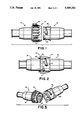
FIG. 1 is a side view of the male and female segments of a presently preferred embodiment of the invention, in uncoupled or valve closed configuration;
FIG. 2 is a side view, partly in section, showing the connector segments of FIG. 1 in coupled or valve opened configuration;
FIG. 3 is a side view corresponding to that of FIG. 1, in full section to show the internal components of the valving mechanism when the connectors are in the uncoupled configuration;
FIG. 4 is a section view of the internal components of the valving mechanism when the connectors are coupled as in FIG. 2; and
FIG. 5 is a perspective view of the two connector segments in the uncoupled state.
Referring now FIGS. 1, 2 and 5 of the drawings, a presently preferred embodiment of an air distribution connector valve 10 according to the invention includes first and second mating connectors 12, 13. Both the male connector 12 and the female connector 13 include a "CIR" Series coupling or engagement mechanism of a type widely used for electrical multipin connectors, manufactured by the Veam Division of Litton Systems, Inc. of Watertown, Connecticut. Such connectors are used in military, commercial, medical, geophysical, aerospace, ground support, and other applications, and feature a positive lock, quick-disconnect coupling and dynamic seal mechanism requiring only a quarter of a turn for full mating or release. Full coupling is indicated by audible, visual, and tactile sensing. High shock and vibration resistance to 50 g's are attained without the use of lockwires. The connector design avoids the use of coupling threads, which could gall or bind with wear or contamination. A stainless steel lock ring is provided at the high point of the bayonet ramp of the connector as a wear-free detent for extended coupling life. For a more comprehensive description of the CIR Series connector coupling mechanism, the reader is referred to descriptive literature for the connectors and to the connectors themselves, available from the Litton Veam Division.
For purposes of the present invention it is sufficient to note that the coupling mechanism of the connectors is configured as follows. Female connector 13 has three equally spaced lugs or teeth 15 disposed internally on and integral with a captive, rotatable ring 17. A portion of the female connector is shown in section in FIG. 1 to illustrate more clearly the location of one of the lugs 15 on the inner surface of ring 17. Male connector 12 has three equally spaced helical grooves 20 in a circumferential collar 22. The grooves 20 are arranged and adapted to receive and accept the lugs 15 of the female connector, so that after the connectors 12 and 13 are placed in confronting relationship and the end 22 of male connector 12 is inserted with proper alignment into the rotatable ring 17, the lugs are engaged in the grooves.
As shown in FIG. 2, the connectors 12 and 13 are fully coupled by rotating the ring 17 in a clockwise direction (as viewed from the left side of the Figure), thereby forcing the lugs 15 along the helical paths of grooves 20 until each of the lugs is positioned over center on a respective pin 25 near the end of the associated groove and finally resides seated against the end of the groove. The lugs are maintained in that position under the force of rearward axial tension placed on the lugs by a wave spring or wave washer 23 which is seated, together with an associated flat washer 24, between confronting flanges of ring 17 and the connector 13 body. In this manner, the male and female connector halves are maintained in positive locking connection, with the edge of ring 17 disposed in close proximity to a flange 27 of male connector 12. The user is thereby provided with visual, audible and tactile evidence that the two connectors are fully coupled together.
When the two connectors are to be separated (uncoupled), the user simply grasps the rotatable ring 17 with one hand, and exerts a force toward the male connector while twisting the ring in the counter-clockwise direction (as viewed in the same direction as before), to overcome the tension on locking pins 25 and return the lugs 15 along the grooves 20 to the exit points. Connector 13 is then merely pulled from connector 12 to fully uncouple the two. Thus, the connectors are readily coupled and uncoupled using only one hand. This assumes, of course, that one or both of the connector bodies are held to preclude rotation, but to allow sufficient axial movement for manual separation and recoupling.
Referring now to FIGS. 3 and 4, the presently preferred embodiment of the invention includes a sliding valve 30 having a substantially cylindrical body portion which is positioned along the axis of symmetry of housing 31 of female connector 13. Valve 30 is provided with an angled surface 32 which conforms to a similarly angled internal surface 35 of the end wall of housing 31. These two angled surfaces are urged toward one another and, but for the presence of a sealing O-ring 64 therebetween, would fully seat against each other. The O-ring is compressed under the force exerted by a compression spring 37. The compression spring is retained between a collar 38 of an opposite angled internal surface 39 of housing 31 and three spacers or lugs 40 equally spaced about the periphery of sliding valve 30. A conical portion 42 of the surface of valve 30 resides within spring 37 in the assembly of the female connector. Spacers 40 serve to separate the valve 30 from the internal tubular surface 45 of housing 31 and to enable the valve to slide axially along that surface under oppositely directed forces exerted by or against the compression spring. It is important to note that the openings between the three separated spacers 40 provides three passageways between opposite ends of the valve body.
A cylindrical end portion 47 of sliding valve 30 normally projects through the circular opening 48 in the end wall of valve housing 31 when the angled surfaces of the valve and the end wall are urged together under the force exerted by the compression spring on the valve body. It will be observed from FIGS. 3 and 4 that a similar configuration of sliding valve 50, spacers 52, compression spring 53, and related internal surfaces of a housing 55, is provided within male connector 12. The cylindrical end portion 57 of valve 50 normally extends through a cylindrical hole 58 at the end wall of housing 55 under the influence of compression spring 53 on the valve. It will be understood, of course, that the two valve housings 31 and 55 are fabricated in any suitable manner to permit ease of assembly of the internal piece parts. For example, each of those housings may consist of two threaded mating halves which, when screwed together as at 66, 67, respectively, form a rigid housing body with a fluid-tight seal.
When the two connectors are brought together for coupling in the manner described above, the end portion 47 of sliding valve 30 and the end portion 57 of sliding valve 50 of respective connectors 13 and 12 abut against one another, causing interference between the two valves and forcing each to slide back against the force exerted by the associated compression spring. When the two connectors are fully coupled, a virtually unrestricted passageway exists between the opening 61 of connector 12 and the opening 62 of connector 13, via the openings between the respective sets of separated spacers 52 and 40 and the end wall openings 58 and 48, as shown more clearly in FIG. 4. In practice, the openings 61 and 62 of the two connectors are coupled to hoses for the desired air distribution from a supply to the user.
When the two connectors are uncoupled, the resulting removal of force against the compression spring in each connector causes the latter to urge its associated valve back to its normal seated position against the respective end wall to automatically shut off the distribution of air through the connector valve. The O-rings 64 seated on respective cylindrical surfaces adjacent the angled surfaces of the two sliding valve bodies assure an effective seal against the passage of air when the valve is closed.
Although a presently preferred embodiment of the invention has been disclosed herein, it will be apparent to those of ordinary skill in the field to which the invention pertains that variations and modifications of the described embodiment may be made without departing from the true spirit and scope of the invention. For example, the invention may be utilized as a valving mechanism for gases, or more broadly, fluids, other than air. Accordingly, it is intended that the invention be limited only to the extent required by the appended claims and the pertinent rules of law.
Claims (1)
1. An air distribution connector valve comprising:
first and second mating connectors;
each connector including a self-closing, one way valve arranged and adapted to interfere with the valve of the other connector when the two connectors are mated together, whereby to open the two valves for unrestricted passage of air therethrough;
each connector includes engagement means for separably coupling the two connectors together to produce the interference between said valves;
each valve includes a valve body, and a compression spring associated and aligned therewith;
each connector further includes a valve housing having an axis of symmetry; the valve body of each connector being retained and slidable axially within the valve housing against the force exerted by the associated compression spring, and the valve body being normally urged by the associated compression spring against an end wall of the housing having a circular opening therein, so that the valve body is normally seated against the end wall to block said opening;
said valve body is cylindrical and includes spacing means on its cylindrical surface for separating the valve body from the inner surface of the associated valve housing,
said spacing means have holes therein to allow passage of air therethrough from the opening in said end wall to the other end of the associated valve housing when the valve body is unseated from said end wall;
each said valve body includes an end portion axially projecting through said opening when the valve body is normally seated against the end wall of the associated valve housing, said end portion having an end surface arranged and adapted to confront and abut against the end surface of the valve body of the other connector and to interfere with one another as the two connectors are being coupled together, so that both valve bodies are unseated from the end wall of their associated valve housings when the two connectors are fully coupled together and are reseated when the two connectors are fully uncoupled, whereby an air distribution passageway is formed through the entirety of the coupled connectors and is automatically closed at each half of the uncoupled connectors;
said engagement means of one of said connectors includes a captive, rotatable ring having a plurality of spaced teeth on the inner surface of said ring;
said engagement means of the other connector includes a plurality of helical grooves equal in number to the number of said teeth, and arranged and adapted to receive and accept the teeth, and, when accepted and the ring is rotated, the teeth ride within the helical grooves to fully couple or uncouple the connectors depending on the direction of rotation of the ring;
said engagement means of the other connector further includes pin means for locking the teeth in position at the end of each of the associated helical grooves, said teeth and said pin means being releasable by exertion of pressure on the ring in the direction opposite that in which the teeth were fully engaged in the helical grooves.
Priority Applications (1)
| Application Number | Priority Date | Filing Date | Title |
|---|---|---|---|
| US07/519,518 US5009252A (en) | 1990-05-03 | 1990-05-03 | Air distribution connector valve |
Applications Claiming Priority (1)
| Application Number | Priority Date | Filing Date | Title |
|---|---|---|---|
| US07/519,518 US5009252A (en) | 1990-05-03 | 1990-05-03 | Air distribution connector valve |
Publications (1)
| Publication Number | Publication Date |
|---|---|
| US5009252A true US5009252A (en) | 1991-04-23 |
Family
ID=24068654
Family Applications (1)
| Application Number | Title | Priority Date | Filing Date |
|---|---|---|---|
| US07/519,518 Expired - Fee Related US5009252A (en) | 1990-05-03 | 1990-05-03 | Air distribution connector valve |
Country Status (1)
| Country | Link |
|---|---|
| US (1) | US5009252A (en) |
Cited By (76)
| Publication number | Priority date | Publication date | Assignee | Title |
|---|---|---|---|---|
| US5174373A (en) * | 1990-07-13 | 1992-12-29 | Sanden Corporation | Heat exchanger |
| US5187316A (en) * | 1990-12-03 | 1993-02-16 | Luwa Ltd. | Passive explosion protection device |
| FR2681398A1 (en) * | 1991-09-17 | 1993-03-19 | Leonard Andre | Body of non-return valve which can be opened rapidly |
| US5257653A (en) * | 1991-11-05 | 1993-11-02 | Precision General Inc. | Ejector pull away system and apparatus |
| US5738143A (en) * | 1996-08-08 | 1998-04-14 | The United States Of America As Represented By The Secretary Of The Army | Butterfly actuated quick coupling connector valve |
| US5799987A (en) * | 1995-06-05 | 1998-09-01 | Sampson; Richard K. | Fluid fitting coupling system |
| US20030085574A1 (en) * | 2001-11-06 | 2003-05-08 | Jean-Paul Froment | Quick connection for the removable join of two pipes |
| US20040040596A1 (en) * | 2002-08-27 | 2004-03-04 | Lung-Po Tsai | Valve used for an inflatable article |
| US20050022883A1 (en) * | 2003-07-29 | 2005-02-03 | Paul Adams | Fuel cartridge with connecting valve |
| US20050082828A1 (en) * | 2003-09-12 | 2005-04-21 | Wicks Jeffrey C. | Releasable connection assembly for joining tubing sections |
| KR100491661B1 (en) * | 2001-09-04 | 2005-05-27 | 유티스타콤코리아 유한회사 | Coupler for isolating fluid |
| US20060278839A1 (en) * | 2003-10-24 | 2006-12-14 | Krywitsky Lee A | Quick disconnect valve assembly |
| US20070102051A1 (en) * | 2005-11-05 | 2007-05-10 | Dennis Zeiber | Threaded coupling with flow shutoff |
| US20070289650A1 (en) * | 2000-07-28 | 2007-12-20 | Krywitsky Lee A | Fluid system coupling with handle actuating member |
| US20080077176A1 (en) * | 2006-09-21 | 2008-03-27 | Tyco Healthcare Group Lp | Safety connector assembly |
| US20090001722A1 (en) * | 2006-01-19 | 2009-01-01 | Toyo Seikan Kaisha, Ltd. | Coupler |
| US20090001720A1 (en) * | 2007-06-30 | 2009-01-01 | Cheon Peter | Coupling with automatic seal |
| US20100059142A1 (en) * | 2005-10-27 | 2010-03-11 | L'air Liquide Societe Anonyme Pour L'etude Et L'exploitation Des Procedes Georges Claude | Gas Filling and Distribution Head Which is Equipped with a Connection Interface and Tank Including One Such Head |
| WO2010040334A1 (en) * | 2008-10-10 | 2010-04-15 | Voelker Manfred | Locking coupling |
| US7762279B2 (en) | 2005-11-05 | 2010-07-27 | Snap-Tite Technologies, Inc. | Threaded coupling with flow shutoff |
| US7770939B2 (en) | 2005-06-10 | 2010-08-10 | Value Plastics, Inc. | Female connector for releasable coupling with a male connector defining a fluid conduit |
| US7806139B2 (en) | 2006-01-20 | 2010-10-05 | Value Plastics, Inc. | Fluid conduit coupling assembly having male and female couplers with integral valves |
| USD629894S1 (en) | 2008-07-03 | 2010-12-28 | Value Plastics, Inc. | Male body of connector for fluid tubing |
| USD630320S1 (en) | 2008-07-03 | 2011-01-04 | Value Plastics, Inc. | Connector for fluid tubing |
| US7878219B2 (en) | 2000-07-28 | 2011-02-01 | Hiltap Fittings, Ltd. | Fluid system coupling with pin lock |
| USD634840S1 (en) | 2008-07-03 | 2011-03-22 | Value Plastics, Inc. | Female body of connector for fluid tubing |
| USD645547S1 (en) | 2007-11-19 | 2011-09-20 | Value Plastics, Inc. | Male quick connect fitting |
| CN101592277B (en) * | 2009-07-10 | 2011-10-19 | 应永华 | Transitional joint of pipe body |
| USD649240S1 (en) | 2009-12-09 | 2011-11-22 | Value Plastics, Inc. | Male dual lumen bayonet connector |
| USD650478S1 (en) | 2009-12-23 | 2011-12-13 | Value Plastics, Inc. | Female dual lumen connector |
| USD652511S1 (en) | 2011-02-11 | 2012-01-17 | Value Plastics, Inc. | Female body of connector for fluid tubing |
| USD652510S1 (en) | 2011-02-11 | 2012-01-17 | Value Plastics, Inc. | Connector for fluid tubing |
| USD655393S1 (en) | 2009-06-23 | 2012-03-06 | Value Plastics, Inc. | Multi-port valve |
| USD663022S1 (en) | 2011-02-11 | 2012-07-03 | Nordson Corporation | Male body of connector for fluid tubing |
| US8225809B2 (en) | 2000-07-28 | 2012-07-24 | Hiltap Fittings, Ltd. | Methods and apparatus for introducing a pig into a fluid system |
| US8235426B2 (en) | 2008-07-03 | 2012-08-07 | Nordson Corporation | Latch assembly for joining two conduits |
| US8257287B2 (en) | 2008-03-20 | 2012-09-04 | Tyco Healthcare Group Lp | Safety connector assembly |
| CN103174894A (en) * | 2011-12-23 | 2013-06-26 | 史陶比尔法万举 | Connector designed to removably connect two fluid channels |
| KR101303208B1 (en) * | 2011-04-20 | 2013-09-04 | 주식회사 바이오알파 | Connecting hose part of A Wound Dressing apparatus |
| WO2013192592A1 (en) * | 2012-06-21 | 2013-12-27 | Robert Bosch Gmbh | Quick connect and quick disconnect system and method of manipulating a quick connect and quick disconnect system |
| USD698440S1 (en) | 2011-07-29 | 2014-01-28 | Nordson Corporation | Connector for fluid tubing |
| USD699841S1 (en) | 2011-07-29 | 2014-02-18 | Nordson Corporation | Female body of connector for fluid tubing |
| USD699840S1 (en) | 2011-07-29 | 2014-02-18 | Nordson Corporation | Male body of connector for fluid tubing |
| USD709612S1 (en) | 2011-12-23 | 2014-07-22 | Nordson Corporation | Female dual lumen connector |
| RU2529430C1 (en) * | 2013-02-09 | 2014-09-27 | Манфред ФЁЛЬКЕР | Connection assembly |
| CN104251357A (en) * | 2013-06-28 | 2014-12-31 | 史陶比尔法万举 | Female quick-connection element and quick connection including such element |
| CN104421195A (en) * | 2013-09-06 | 2015-03-18 | 本田技研工业株式会社 | Hose attaching structure |
| US8985131B2 (en) | 2007-06-30 | 2015-03-24 | Koolance, Inc. | Coupling with automatic seal |
| US8985482B1 (en) * | 2007-11-09 | 2015-03-24 | Fore front Product Design, LLC | Portable pressurized sprayer |
| US9046205B2 (en) | 2009-12-09 | 2015-06-02 | Nordson Corporation | Fluid connector latches with profile lead-ins |
| US20150151102A1 (en) * | 2012-05-24 | 2015-06-04 | Glomeria Therapeutics S.R.L. | Connection device |
| US20150267847A1 (en) * | 2013-09-18 | 2015-09-24 | Shawn Smith | Tool Cabinet Having Integral Air Lines |
| US20150276111A1 (en) * | 2014-03-28 | 2015-10-01 | Eldon James Corp. | Releasable Valved Coupler |
| US20150353340A1 (en) * | 2014-06-10 | 2015-12-10 | Gammon Technical Products, Inc. | Fueling nozzle adapter |
| US20160022979A1 (en) * | 2013-03-29 | 2016-01-28 | Emd Millipore Corporation | Sterile Connection/Disconnection Coupling And Method |
| US9388929B2 (en) | 2009-12-09 | 2016-07-12 | Nordson Corporation | Male bayonet connector |
| US9464741B2 (en) | 2009-12-09 | 2016-10-11 | Nordson Corporation | Button latch with integrally molded cantilever springs |
| US20160356410A1 (en) * | 2014-02-03 | 2016-12-08 | Gaztransport Et Technigaz | Connection device for connecting two fluid circuits |
| USD785790S1 (en) | 2009-12-09 | 2017-05-02 | General Electric Company | Male dual lumen bayonet connector |
| US20170157306A1 (en) * | 2015-12-03 | 2017-06-08 | Guy R. VOELLER | Vacuum assisted drain connector and assembly |
| EP2137448A4 (en) * | 2007-04-18 | 2017-12-27 | Cejn AB | Coaxial coupling with by-pass valve and coupling mechanism with bayonette form |
| US20180094730A1 (en) * | 2016-10-02 | 2018-04-05 | Peter Wojtach | Gas concentrator apparatus and method of use thereof |
| US9989155B2 (en) | 2014-11-10 | 2018-06-05 | Hamilton Sundstrand Corporation | Connector link for butterfly valve |
| US20180161546A1 (en) * | 2016-12-12 | 2018-06-14 | National Guard Health Affairs | Intravenous catheter stopper |
| US10132436B2 (en) | 2013-03-15 | 2018-11-20 | Fiskars Oyj Abp | Quick connect/disconnect adaptor system |
| US10173046B2 (en) | 2016-01-19 | 2019-01-08 | Wilmarc Holdings, Llc | Connector system for releasably connecting fluid conduits |
| USD838366S1 (en) | 2016-10-31 | 2019-01-15 | Nordson Corporation | Blood pressure connector |
| US20190105438A1 (en) * | 2017-10-11 | 2019-04-11 | Heartware, Inc. | Dry disconnect/bubble free coupling for blood transfer |
| US10350401B2 (en) | 2017-03-08 | 2019-07-16 | Wilmarc Holdings, Llc | Catch assembly for releasably connecting fluid conduits |
| US10711930B2 (en) | 2009-12-09 | 2020-07-14 | Nordson Corporation | Releasable connection assembly |
| US20210069484A1 (en) * | 2018-03-19 | 2021-03-11 | Hsi-Chin Tsai | Body-Fluid-And-Medication Leak-Proof and Closed Medical Connector |
| US11549514B2 (en) | 2017-11-27 | 2023-01-10 | Intex Marketing Ltd. | Manual inflation and deflation adjustment structure for a pump |
| US20230087734A1 (en) * | 2018-01-11 | 2023-03-23 | Michael A. Merchant | Closed system elastomeric pumping mechanism |
| US11668310B2 (en) | 2017-11-15 | 2023-06-06 | Intex Marketing Ltd. | Multichannel air pump |
| US11717286B2 (en) * | 2007-01-31 | 2023-08-08 | Covidien Lp | Surgical instrument with replaceable loading unit |
| US20230288003A1 (en) * | 2020-07-03 | 2023-09-14 | Thales Alenia Space Italia S.P.A. Con Unico Socio | Connection Units for Quick Connection/Disconnection Fluidic Lines |
Citations (4)
| Publication number | Priority date | Publication date | Assignee | Title |
|---|---|---|---|---|
| US3028179A (en) * | 1958-12-29 | 1962-04-03 | Weatherhead Co | Self-sealing locking coupling with manipulator and pivoted latch means |
| US3191972A (en) * | 1960-05-09 | 1965-06-29 | Lear Siegler Inc | Quick connect tube coupling having locking means with visual indicator |
| US3478302A (en) * | 1968-03-18 | 1969-11-11 | Bunker Ramo | Electrical connector |
| US3625251A (en) * | 1970-04-15 | 1971-12-07 | Int Harvester Co | Hydraulic coupler |
-
1990
- 1990-05-03 US US07/519,518 patent/US5009252A/en not_active Expired - Fee Related
Patent Citations (4)
| Publication number | Priority date | Publication date | Assignee | Title |
|---|---|---|---|---|
| US3028179A (en) * | 1958-12-29 | 1962-04-03 | Weatherhead Co | Self-sealing locking coupling with manipulator and pivoted latch means |
| US3191972A (en) * | 1960-05-09 | 1965-06-29 | Lear Siegler Inc | Quick connect tube coupling having locking means with visual indicator |
| US3478302A (en) * | 1968-03-18 | 1969-11-11 | Bunker Ramo | Electrical connector |
| US3625251A (en) * | 1970-04-15 | 1971-12-07 | Int Harvester Co | Hydraulic coupler |
Cited By (141)
| Publication number | Priority date | Publication date | Assignee | Title |
|---|---|---|---|---|
| US5174373A (en) * | 1990-07-13 | 1992-12-29 | Sanden Corporation | Heat exchanger |
| US5187316A (en) * | 1990-12-03 | 1993-02-16 | Luwa Ltd. | Passive explosion protection device |
| FR2681398A1 (en) * | 1991-09-17 | 1993-03-19 | Leonard Andre | Body of non-return valve which can be opened rapidly |
| US5257653A (en) * | 1991-11-05 | 1993-11-02 | Precision General Inc. | Ejector pull away system and apparatus |
| US6616197B2 (en) | 1995-06-05 | 2003-09-09 | Kent Systems, Llc | Resilient retention method |
| US5799987A (en) * | 1995-06-05 | 1998-09-01 | Sampson; Richard K. | Fluid fitting coupling system |
| US5937885A (en) * | 1995-06-05 | 1999-08-17 | Value Plastics, Inc. | Fluid fitting coupling system |
| US5738143A (en) * | 1996-08-08 | 1998-04-14 | The United States Of America As Represented By The Secretary Of The Army | Butterfly actuated quick coupling connector valve |
| US8225809B2 (en) | 2000-07-28 | 2012-07-24 | Hiltap Fittings, Ltd. | Methods and apparatus for introducing a pig into a fluid system |
| US7878219B2 (en) | 2000-07-28 | 2011-02-01 | Hiltap Fittings, Ltd. | Fluid system coupling with pin lock |
| US7909365B2 (en) | 2000-07-28 | 2011-03-22 | Hiltap Fittings, Ltd. | Fluid system coupling with handle actuating member |
| US20070289650A1 (en) * | 2000-07-28 | 2007-12-20 | Krywitsky Lee A | Fluid system coupling with handle actuating member |
| KR100491661B1 (en) * | 2001-09-04 | 2005-05-27 | 유티스타콤코리아 유한회사 | Coupler for isolating fluid |
| US6877778B2 (en) * | 2001-11-06 | 2005-04-12 | Staubli Faverges | Linearly actuated quick connect pipe couplings |
| US20030085572A1 (en) * | 2001-11-06 | 2003-05-08 | Jean-Paul Froment | Quick connection for the removable join of two pipes |
| US6905151B2 (en) | 2001-11-06 | 2005-06-14 | Staubli Faverges | Linearly actuated quick connect pipe couplings |
| US20030085574A1 (en) * | 2001-11-06 | 2003-05-08 | Jean-Paul Froment | Quick connection for the removable join of two pipes |
| US6786131B2 (en) * | 2002-08-27 | 2004-09-07 | Lung-Po Tsai | Valve used for an inflatable article |
| US20040040596A1 (en) * | 2002-08-27 | 2004-03-04 | Lung-Po Tsai | Valve used for an inflatable article |
| US20050022883A1 (en) * | 2003-07-29 | 2005-02-03 | Paul Adams | Fuel cartridge with connecting valve |
| US7537024B2 (en) | 2003-07-29 | 2009-05-26 | Societe Bic | Fuel cartridge with connecting valve |
| US20050082828A1 (en) * | 2003-09-12 | 2005-04-21 | Wicks Jeffrey C. | Releasable connection assembly for joining tubing sections |
| US7878553B2 (en) | 2003-09-12 | 2011-02-01 | Value Plastics, Inc. | Releasable connection assembly for joining tubing sections |
| US20060278839A1 (en) * | 2003-10-24 | 2006-12-14 | Krywitsky Lee A | Quick disconnect valve assembly |
| US7686037B2 (en) * | 2003-10-24 | 2010-03-30 | Hiltap Fittings, Ltd. | Quick disconnect valve assembly |
| US8113546B2 (en) | 2005-06-10 | 2012-02-14 | Value Plastics, Inc. | Latching female fluid tubing coupler |
| US7770939B2 (en) | 2005-06-10 | 2010-08-10 | Value Plastics, Inc. | Female connector for releasable coupling with a male connector defining a fluid conduit |
| US20100059142A1 (en) * | 2005-10-27 | 2010-03-11 | L'air Liquide Societe Anonyme Pour L'etude Et L'exploitation Des Procedes Georges Claude | Gas Filling and Distribution Head Which is Equipped with a Connection Interface and Tank Including One Such Head |
| US7762279B2 (en) | 2005-11-05 | 2010-07-27 | Snap-Tite Technologies, Inc. | Threaded coupling with flow shutoff |
| US20070102051A1 (en) * | 2005-11-05 | 2007-05-10 | Dennis Zeiber | Threaded coupling with flow shutoff |
| US20090001722A1 (en) * | 2006-01-19 | 2009-01-01 | Toyo Seikan Kaisha, Ltd. | Coupler |
| US8490650B2 (en) * | 2006-01-19 | 2013-07-23 | Toyo Seikan Kaisha, Ltd. | Coupler for transferring a liquid or other material between containers |
| US7806139B2 (en) | 2006-01-20 | 2010-10-05 | Value Plastics, Inc. | Fluid conduit coupling assembly having male and female couplers with integral valves |
| US8397756B2 (en) | 2006-01-20 | 2013-03-19 | Nordson Corporation | Fluid conduit couplers with depressible latch mechanism |
| US8257286B2 (en) * | 2006-09-21 | 2012-09-04 | Tyco Healthcare Group Lp | Safety connector apparatus |
| US20080077176A1 (en) * | 2006-09-21 | 2008-03-27 | Tyco Healthcare Group Lp | Safety connector assembly |
| US8287517B2 (en) | 2006-09-21 | 2012-10-16 | Tyco Healtcare Group Lp | Safety connector assembly |
| US20080077063A1 (en) * | 2006-09-21 | 2008-03-27 | Tyco Healthcare Group Lp | Safety Connector Apparatus |
| US9687249B2 (en) | 2006-09-21 | 2017-06-27 | Covidien Lp | Safety connector assembly |
| US11717286B2 (en) * | 2007-01-31 | 2023-08-08 | Covidien Lp | Surgical instrument with replaceable loading unit |
| EP2137448A4 (en) * | 2007-04-18 | 2017-12-27 | Cejn AB | Coaxial coupling with by-pass valve and coupling mechanism with bayonette form |
| US20090001720A1 (en) * | 2007-06-30 | 2009-01-01 | Cheon Peter | Coupling with automatic seal |
| US8985131B2 (en) | 2007-06-30 | 2015-03-24 | Koolance, Inc. | Coupling with automatic seal |
| US8985482B1 (en) * | 2007-11-09 | 2015-03-24 | Fore front Product Design, LLC | Portable pressurized sprayer |
| US20150258558A1 (en) * | 2007-11-09 | 2015-09-17 | Forefront Product Design, L.L.C. | Portable pressurized sprayer |
| US10112204B2 (en) * | 2007-11-09 | 2018-10-30 | Forefront Product Design, Llc | Portable pressurized sprayer |
| USD654573S1 (en) | 2007-11-19 | 2012-02-21 | Value Plastics, Inc. | Female quick connect fitting |
| USD645547S1 (en) | 2007-11-19 | 2011-09-20 | Value Plastics, Inc. | Male quick connect fitting |
| US8257287B2 (en) | 2008-03-20 | 2012-09-04 | Tyco Healthcare Group Lp | Safety connector assembly |
| US8448994B2 (en) | 2008-07-03 | 2013-05-28 | Nordson Corporation | Latch assembly for joining two conduits |
| USD630320S1 (en) | 2008-07-03 | 2011-01-04 | Value Plastics, Inc. | Connector for fluid tubing |
| USD634840S1 (en) | 2008-07-03 | 2011-03-22 | Value Plastics, Inc. | Female body of connector for fluid tubing |
| USD629894S1 (en) | 2008-07-03 | 2010-12-28 | Value Plastics, Inc. | Male body of connector for fluid tubing |
| US8235426B2 (en) | 2008-07-03 | 2012-08-07 | Nordson Corporation | Latch assembly for joining two conduits |
| US8596688B2 (en) | 2008-07-03 | 2013-12-03 | Nordson Corporation | Latch assembly for joining two conduits |
| RU2461763C1 (en) * | 2008-10-10 | 2012-09-20 | Манфред ФЁЛЬКЕР | Connection unit |
| WO2010040334A1 (en) * | 2008-10-10 | 2010-04-15 | Voelker Manfred | Locking coupling |
| USD655393S1 (en) | 2009-06-23 | 2012-03-06 | Value Plastics, Inc. | Multi-port valve |
| CN101592277B (en) * | 2009-07-10 | 2011-10-19 | 应永华 | Transitional joint of pipe body |
| US10001236B2 (en) | 2009-12-09 | 2018-06-19 | General Electric Company | Male bayonet connector |
| US9046205B2 (en) | 2009-12-09 | 2015-06-02 | Nordson Corporation | Fluid connector latches with profile lead-ins |
| US10711930B2 (en) | 2009-12-09 | 2020-07-14 | Nordson Corporation | Releasable connection assembly |
| US9732891B2 (en) | 2009-12-09 | 2017-08-15 | General Electric Company | Male bayonet connector |
| USD785790S1 (en) | 2009-12-09 | 2017-05-02 | General Electric Company | Male dual lumen bayonet connector |
| US9464741B2 (en) | 2009-12-09 | 2016-10-11 | Nordson Corporation | Button latch with integrally molded cantilever springs |
| US9388929B2 (en) | 2009-12-09 | 2016-07-12 | Nordson Corporation | Male bayonet connector |
| USD649240S1 (en) | 2009-12-09 | 2011-11-22 | Value Plastics, Inc. | Male dual lumen bayonet connector |
| USD650478S1 (en) | 2009-12-23 | 2011-12-13 | Value Plastics, Inc. | Female dual lumen connector |
| USD652511S1 (en) | 2011-02-11 | 2012-01-17 | Value Plastics, Inc. | Female body of connector for fluid tubing |
| USD652510S1 (en) | 2011-02-11 | 2012-01-17 | Value Plastics, Inc. | Connector for fluid tubing |
| USD663022S1 (en) | 2011-02-11 | 2012-07-03 | Nordson Corporation | Male body of connector for fluid tubing |
| KR101303208B1 (en) * | 2011-04-20 | 2013-09-04 | 주식회사 바이오알파 | Connecting hose part of A Wound Dressing apparatus |
| USD712537S1 (en) | 2011-07-29 | 2014-09-02 | Nordson Corporation | Connector for fluid tubing |
| USD698440S1 (en) | 2011-07-29 | 2014-01-28 | Nordson Corporation | Connector for fluid tubing |
| USD699841S1 (en) | 2011-07-29 | 2014-02-18 | Nordson Corporation | Female body of connector for fluid tubing |
| USD699840S1 (en) | 2011-07-29 | 2014-02-18 | Nordson Corporation | Male body of connector for fluid tubing |
| USD709612S1 (en) | 2011-12-23 | 2014-07-22 | Nordson Corporation | Female dual lumen connector |
| CN103174894B (en) * | 2011-12-23 | 2016-08-10 | 史陶比尔法万举 | Adapter for two fluid passages that removably connect |
| US20130160880A1 (en) * | 2011-12-23 | 2013-06-27 | Staubli Faverges | Connector designed to removably connect two fluid channels |
| CN103174894A (en) * | 2011-12-23 | 2013-06-26 | 史陶比尔法万举 | Connector designed to removably connect two fluid channels |
| US8899550B2 (en) * | 2011-12-23 | 2014-12-02 | Staubli Faverges | Connector designed to removably connect two fluid channels |
| US20150151102A1 (en) * | 2012-05-24 | 2015-06-04 | Glomeria Therapeutics S.R.L. | Connection device |
| AU2013278027B2 (en) * | 2012-06-21 | 2017-06-15 | Fiskars Finland Oy Ab | Quick connect and quick disconnect system and method of manipulating a quick connect and quick disconnect system |
| US9845909B2 (en) | 2012-06-21 | 2017-12-19 | Fiskars Oyj Abp | Quick connect and quick disconnect system and method of manipulating a quick connect and quick disconnect system |
| CN104685282A (en) * | 2012-06-21 | 2015-06-03 | 菲斯卡公司 | Quick connect and quick disconnect system and method of manipulating a quick connect and quick disconnect system |
| WO2013192592A1 (en) * | 2012-06-21 | 2013-12-27 | Robert Bosch Gmbh | Quick connect and quick disconnect system and method of manipulating a quick connect and quick disconnect system |
| US9863567B2 (en) | 2012-06-21 | 2018-01-09 | Fiskars Oyj Abp | Quick connect and quick disconnect system and method of manipulating a quick connect and quick disconnect system |
| US9568135B2 (en) | 2012-06-21 | 2017-02-14 | Fiskars Oyj Abp | Quick connect and quick disconnect system with positive feedback and method of manipulating a quick connect and quick disconnect system with positive feedback |
| US9291294B2 (en) | 2012-06-21 | 2016-03-22 | Fiskars Oyj Abp | Quick connect and quick disconnect system |
| US9664322B2 (en) | 2012-06-21 | 2017-05-30 | Fiskars Oyj Abp | Quick connect and quick disconnect system male component |
| RU2529430C1 (en) * | 2013-02-09 | 2014-09-27 | Манфред ФЁЛЬКЕР | Connection assembly |
| US10132436B2 (en) | 2013-03-15 | 2018-11-20 | Fiskars Oyj Abp | Quick connect/disconnect adaptor system |
| US9901729B2 (en) * | 2013-03-29 | 2018-02-27 | Emd Millipore Corporation | Sterile connection/disconnection coupling and method |
| US20160022979A1 (en) * | 2013-03-29 | 2016-01-28 | Emd Millipore Corporation | Sterile Connection/Disconnection Coupling And Method |
| US10940307B2 (en) | 2013-03-29 | 2021-03-09 | Emd Millipore Corporation | Sterile connection/disconnection coupling and method |
| US10675454B2 (en) | 2013-03-29 | 2020-06-09 | Emd Millipore Corporation | Sterile connection/disconnection coupling and method |
| US20150001844A1 (en) * | 2013-06-28 | 2015-01-01 | Staubli Faverges | Female Quick Coupling Element and Quick Coupling Including Such an Element |
| US9360142B2 (en) * | 2013-06-28 | 2016-06-07 | Staubli Faverges | Female quick coupling element and quick coupling including such an element |
| CN104251357A (en) * | 2013-06-28 | 2014-12-31 | 史陶比尔法万举 | Female quick-connection element and quick connection including such element |
| CN104421195A (en) * | 2013-09-06 | 2015-03-18 | 本田技研工业株式会社 | Hose attaching structure |
| US9895797B2 (en) * | 2013-09-18 | 2018-02-20 | Shawn Smith | Tool cabinet having integral air lines |
| US20150267847A1 (en) * | 2013-09-18 | 2015-09-24 | Shawn Smith | Tool Cabinet Having Integral Air Lines |
| US20160356410A1 (en) * | 2014-02-03 | 2016-12-08 | Gaztransport Et Technigaz | Connection device for connecting two fluid circuits |
| US10731783B2 (en) * | 2014-02-03 | 2020-08-04 | Gaztransport Et Technigaz | Connection device for connecting two fluid circuits |
| US9752714B2 (en) * | 2014-03-28 | 2017-09-05 | Eldon James Corp. | Releasable valved coupler |
| US10267445B2 (en) | 2014-03-28 | 2019-04-23 | Craig Alan Ira | Releasable valved coupler |
| US20150276111A1 (en) * | 2014-03-28 | 2015-10-01 | Eldon James Corp. | Releasable Valved Coupler |
| US9938022B2 (en) * | 2014-06-10 | 2018-04-10 | Gammon Technical Products, Inc. | Fueling nozzle adapter |
| US20150353340A1 (en) * | 2014-06-10 | 2015-12-10 | Gammon Technical Products, Inc. | Fueling nozzle adapter |
| US10960990B2 (en) | 2014-06-10 | 2021-03-30 | Gammon Technical Products, Inc. | Fueling nozzle adaptor |
| US9989155B2 (en) | 2014-11-10 | 2018-06-05 | Hamilton Sundstrand Corporation | Connector link for butterfly valve |
| US20170157306A1 (en) * | 2015-12-03 | 2017-06-08 | Guy R. VOELLER | Vacuum assisted drain connector and assembly |
| US10293087B2 (en) * | 2015-12-03 | 2019-05-21 | Vacuus, Llc | Vacuum assisted drain connector and assembly |
| US11534594B2 (en) | 2016-01-19 | 2022-12-27 | Wilmarc Holdings, Llc | Connector system for releasably connecting fluid conduits |
| US11883624B2 (en) | 2016-01-19 | 2024-01-30 | Wilmarc Holdings, Llc | Connector system for releasably connecting fluid conduits |
| US11478626B2 (en) | 2016-01-19 | 2022-10-25 | Wilmarc Holdings, Llc | Connector system for releasably connecting fluid conduits |
| US11478625B2 (en) | 2016-01-19 | 2022-10-25 | Wilmarc Holdings, Llc | Connector system for releasably connecting fluid conduits |
| US10293150B2 (en) | 2016-01-19 | 2019-05-21 | Wilmarc Holdings, Llc | Connector system for releasably connecting fluid conduits |
| US11027111B2 (en) | 2016-01-19 | 2021-06-08 | Wilmarc Holdings, Llc | Connector system for releasably connecting fluid conduits |
| US10173046B2 (en) | 2016-01-19 | 2019-01-08 | Wilmarc Holdings, Llc | Connector system for releasably connecting fluid conduits |
| US10982773B2 (en) * | 2016-10-02 | 2021-04-20 | Peter Wojtach | Gas concentrator apparatus and method of use thereof |
| US20180094730A1 (en) * | 2016-10-02 | 2018-04-05 | Peter Wojtach | Gas concentrator apparatus and method of use thereof |
| USD838366S1 (en) | 2016-10-31 | 2019-01-15 | Nordson Corporation | Blood pressure connector |
| USD964557S1 (en) | 2016-10-31 | 2022-09-20 | Nordson Corporation | Blood pressure connector |
| USD967955S1 (en) | 2016-10-31 | 2022-10-25 | Nordson Corporation | Blood pressure connector |
| USD961070S1 (en) | 2016-10-31 | 2022-08-16 | Nordson Corporation | Blood pressure connector |
| USD964558S1 (en) | 2016-10-31 | 2022-09-20 | Nordson Corporation | Blood pressure connector |
| US20180161546A1 (en) * | 2016-12-12 | 2018-06-14 | National Guard Health Affairs | Intravenous catheter stopper |
| US10350401B2 (en) | 2017-03-08 | 2019-07-16 | Wilmarc Holdings, Llc | Catch assembly for releasably connecting fluid conduits |
| US11191942B2 (en) | 2017-03-08 | 2021-12-07 | Wilmarc Holdings, Llc | Catch assembly for releasably connecting fluid conduits |
| US10583281B2 (en) | 2017-03-08 | 2020-03-10 | Wilmarc Holdings, Llc | Catch assembly for releasably connecting fluid conduits |
| US10864364B2 (en) * | 2017-10-11 | 2020-12-15 | Heartware, Inc. | Dry disconnect/bubble free coupling for blood transfer |
| US20190105438A1 (en) * | 2017-10-11 | 2019-04-11 | Heartware, Inc. | Dry disconnect/bubble free coupling for blood transfer |
| US11173295B2 (en) | 2017-10-11 | 2021-11-16 | Heartware Inc. | Dry disconnect/bubble free coupling for blood transfer |
| US11668310B2 (en) | 2017-11-15 | 2023-06-06 | Intex Marketing Ltd. | Multichannel air pump |
| US11549514B2 (en) | 2017-11-27 | 2023-01-10 | Intex Marketing Ltd. | Manual inflation and deflation adjustment structure for a pump |
| US11913462B2 (en) | 2017-11-27 | 2024-02-27 | Intex Marketing Ltd. | Manual inflation and deflation adjustment structure for a pump |
| US20230087734A1 (en) * | 2018-01-11 | 2023-03-23 | Michael A. Merchant | Closed system elastomeric pumping mechanism |
| US20210069484A1 (en) * | 2018-03-19 | 2021-03-11 | Hsi-Chin Tsai | Body-Fluid-And-Medication Leak-Proof and Closed Medical Connector |
| US11865293B2 (en) * | 2018-03-19 | 2024-01-09 | Hsi-Chin Tsai | Body-fluid-and-medication leak-proof and closed medical connector |
| US20230288003A1 (en) * | 2020-07-03 | 2023-09-14 | Thales Alenia Space Italia S.P.A. Con Unico Socio | Connection Units for Quick Connection/Disconnection Fluidic Lines |
Similar Documents
| Publication | Publication Date | Title |
|---|---|---|
| US5009252A (en) | Air distribution connector valve | |
| US4522639A (en) | Unified filter and connector housing assembly incorporating a diversion valve | |
| US5738143A (en) | Butterfly actuated quick coupling connector valve | |
| US10632331B2 (en) | Quick connect pressure reducer/cylinder valve for self-contained breathing apparatus | |
| US5197766A (en) | Fluid-carrying tube coupling assembly with internal seal and drain arrangement | |
| US3215161A (en) | Self-sealing coupling | |
| US5709204A (en) | Aircraft passenger oxygen, survival and escape mask | |
| US4619255A (en) | Oxygen supply system | |
| CA2151049C (en) | Push-to-connect coupler with interlocking three-way valve | |
| GB2069083A (en) | Pipe coupling | |
| AU2014229778B2 (en) | Respirator filter interface | |
| CA1320519C (en) | Straight connecting hydraulic quick coupler | |
| US4978150A (en) | Quick disconnect fluid coupling | |
| US5083818A (en) | Quick disconnect fluid coupling | |
| US4506862A (en) | Fluid hose connectors | |
| US3872556A (en) | Gas operated quick disconnect coupling | |
| CN108057187B (en) | Connecting assembly capable of being rapidly connected with other rescue breathing mask with air | |
| US4378795A (en) | Fluid connector assembly | |
| US4527816A (en) | Safety coupling arrangement | |
| US3016061A (en) | Emergency oxygen release system and coupling | |
| CN109045501A (en) | The coupling device of breathing apparatus | |
| US3093357A (en) | Pressurized fluid coupling means | |
| CN108744333B (en) | Air respirator | |
| EP0472652B1 (en) | Improved quick disconnect coupling | |
| GB2574340A (en) | A self contained breathing apparatus connector and method of manufacture thereof |
Legal Events
| Date | Code | Title | Description |
|---|---|---|---|
| FPAY | Fee payment |
Year of fee payment: 4 |
|
| REMI | Maintenance fee reminder mailed | ||
| LAPS | Lapse for failure to pay maintenance fees | ||
| FP | Lapsed due to failure to pay maintenance fee |
Effective date: 19990423 |
|
| STCH | Information on status: patent discontinuation |
Free format text: PATENT EXPIRED DUE TO NONPAYMENT OF MAINTENANCE FEES UNDER 37 CFR 1.362 |