US5019256A - Ultraviolet lamp rack assembly - Google Patents
Ultraviolet lamp rack assembly Download PDFInfo
- Publication number
- US5019256A US5019256A US07/600,597 US60059790A US5019256A US 5019256 A US5019256 A US 5019256A US 60059790 A US60059790 A US 60059790A US 5019256 A US5019256 A US 5019256A
- Authority
- US
- United States
- Prior art keywords
- lamp
- assembly
- unit
- coupler
- sleeve
- Prior art date
- Legal status (The legal status is an assumption and is not a legal conclusion. Google has not performed a legal analysis and makes no representation as to the accuracy of the status listed.)
- Expired - Fee Related
Links
- 238000011144 upstream manufacturing Methods 0.000 claims abstract description 35
- 230000001681 protective effect Effects 0.000 claims abstract description 6
- XLYOFNOQVPJJNP-UHFFFAOYSA-N water Substances O XLYOFNOQVPJJNP-UHFFFAOYSA-N 0.000 claims description 21
- 230000000712 assembly Effects 0.000 claims description 8
- 238000000429 assembly Methods 0.000 claims description 8
- 125000006850 spacer group Chemical group 0.000 claims description 5
- 239000004033 plastic Substances 0.000 claims description 4
- 229920003023 plastic Polymers 0.000 claims description 4
- 239000000463 material Substances 0.000 claims description 3
- 239000013536 elastomeric material Substances 0.000 claims description 2
- 238000007789 sealing Methods 0.000 claims 1
- 239000002351 wastewater Substances 0.000 abstract description 5
- 238000004065 wastewater treatment Methods 0.000 abstract description 5
- 230000005855 radiation Effects 0.000 description 11
- 239000010453 quartz Substances 0.000 description 10
- VYPSYNLAJGMNEJ-UHFFFAOYSA-N silicon dioxide Inorganic materials O=[Si]=O VYPSYNLAJGMNEJ-UHFFFAOYSA-N 0.000 description 10
- 238000004659 sterilization and disinfection Methods 0.000 description 9
- 229910052751 metal Inorganic materials 0.000 description 7
- 239000002184 metal Substances 0.000 description 7
- 238000005660 chlorination reaction Methods 0.000 description 4
- 239000007788 liquid Substances 0.000 description 4
- 230000001954 sterilising effect Effects 0.000 description 3
- ZAMOUSCENKQFHK-UHFFFAOYSA-N Chlorine atom Chemical compound [Cl] ZAMOUSCENKQFHK-UHFFFAOYSA-N 0.000 description 2
- 229910052801 chlorine Inorganic materials 0.000 description 2
- 239000000460 chlorine Substances 0.000 description 2
- 238000012423 maintenance Methods 0.000 description 2
- 238000000034 method Methods 0.000 description 2
- 244000005700 microbiome Species 0.000 description 2
- -1 polyethylene Polymers 0.000 description 2
- 239000004698 Polyethylene Substances 0.000 description 1
- 239000004743 Polypropylene Substances 0.000 description 1
- 238000003491 array Methods 0.000 description 1
- 230000004888 barrier function Effects 0.000 description 1
- 230000008901 benefit Effects 0.000 description 1
- 150000001805 chlorine compounds Chemical class 0.000 description 1
- 230000000249 desinfective effect Effects 0.000 description 1
- 230000035622 drinking Effects 0.000 description 1
- 230000007613 environmental effect Effects 0.000 description 1
- 239000006260 foam Substances 0.000 description 1
- 230000002070 germicidal effect Effects 0.000 description 1
- 230000000266 injurious effect Effects 0.000 description 1
- 238000007689 inspection Methods 0.000 description 1
- 239000012212 insulator Substances 0.000 description 1
- QSHDDOUJBYECFT-UHFFFAOYSA-N mercury Chemical compound [Hg] QSHDDOUJBYECFT-UHFFFAOYSA-N 0.000 description 1
- 238000012986 modification Methods 0.000 description 1
- 230000004048 modification Effects 0.000 description 1
- 210000002445 nipple Anatomy 0.000 description 1
- 230000009972 noncorrosive effect Effects 0.000 description 1
- 229920001084 poly(chloroprene) Polymers 0.000 description 1
- 229920000573 polyethylene Polymers 0.000 description 1
- 229920001155 polypropylene Polymers 0.000 description 1
- 229920002635 polyurethane Polymers 0.000 description 1
- 239000004814 polyurethane Substances 0.000 description 1
- 230000008439 repair process Effects 0.000 description 1
- 229910001220 stainless steel Inorganic materials 0.000 description 1
- 239000010935 stainless steel Substances 0.000 description 1
- 239000003351 stiffener Substances 0.000 description 1
- 239000000126 substance Substances 0.000 description 1
- 239000003643 water by type Substances 0.000 description 1
Images


Classifications
-
- C—CHEMISTRY; METALLURGY
- C02—TREATMENT OF WATER, WASTE WATER, SEWAGE, OR SLUDGE
- C02F—TREATMENT OF WATER, WASTE WATER, SEWAGE, OR SLUDGE
- C02F1/00—Treatment of water, waste water, or sewage
- C02F1/30—Treatment of water, waste water, or sewage by irradiation
- C02F1/32—Treatment of water, waste water, or sewage by irradiation with ultraviolet light
- C02F1/325—Irradiation devices or lamp constructions
-
- B—PERFORMING OPERATIONS; TRANSPORTING
- B01—PHYSICAL OR CHEMICAL PROCESSES OR APPARATUS IN GENERAL
- B01J—CHEMICAL OR PHYSICAL PROCESSES, e.g. CATALYSIS OR COLLOID CHEMISTRY; THEIR RELEVANT APPARATUS
- B01J19/00—Chemical, physical or physico-chemical processes in general; Their relevant apparatus
- B01J19/08—Processes employing the direct application of electric or wave energy, or particle radiation; Apparatus therefor
- B01J19/12—Processes employing the direct application of electric or wave energy, or particle radiation; Apparatus therefor employing electromagnetic waves
- B01J19/122—Incoherent waves
- B01J19/123—Ultra-violet light
-
- C—CHEMISTRY; METALLURGY
- C02—TREATMENT OF WATER, WASTE WATER, SEWAGE, OR SLUDGE
- C02F—TREATMENT OF WATER, WASTE WATER, SEWAGE, OR SLUDGE
- C02F2201/00—Apparatus for treatment of water, waste water or sewage
- C02F2201/32—Details relating to UV-irradiation devices
- C02F2201/322—Lamp arrangement
- C02F2201/3227—Units with two or more lamps
Definitions
- This invention relates generally to a UV lamp rack assembly for use in ultraviolet ray water and wastewater treatment systems, and more particularly to a modular assembly in which a vertical array of UV lamp units is supported on a rack, each unit being separately removable from the rack without disturbing the other units.
- Chlorination has heretofore been the most commonly used technique for disinfecting large quantities of wastewater. Chlorination involves the addition of small amounts of chlorine or chlorine compounds to the water to destroy undesirable microorganisms.
- a disadvantage peculiar to disinfection of the effluent of a wastewater treatment plant by chlorination is that such disinfection leaves a residual. This residual can be environmentally harmful, or undesirable should the body of water receiving the chlorinated discharge be reused for drinking waster.
- Other factors that must be taken into account are the hazards associated with transporting and storing chlorine in populated areas.
- UV radiation at certain wavelengths has powerful germicidal properties, as a consequence of which the use of UV radiation for purposes of wastewater disinfection has been gaining rapidly in popularity.
- a source of ultraviolet radiation such as a bank of ultraviolet lamps is housed in a chamber through which the liquid to be treated is caused to flow, the liquid being subjected to UV radiation in the course of its passage through the chamber.
- ultraviolet lamps producing ultraviolet radiation of a suitable wavelength typically 2540 Angstroms
- a lamp By failure is meant not only a lamp that is altogether inoperative, but one whose level of radiation has fallen to an unacceptable degree.
- One approach to UV lamp replacement is disclosed in the Maarschalkeweerd U.S. Pat. No. 4,482,809, in which groups of vertically adjacent lamps are supported in individual rack assemblies which can be withdrawn from a treatment channel for replacement of the lamps.
- the lamps are housed in transparent quartz tubes extending between sockets integral with the side arms of a rigid frame, at least one of the sockets having an end plug through which a lamp can be withdrawn longitudinally once the frame has been withdrawn from the channel.
- This arrangement is relatively complex to fabricate. And while it may appear to be advantageous that the lamps are rigidly secured to the frame, in practice any distortion of the frame during handling will strain the quartz tubes containing the lamps, thereby risking breakage.
- individual ultraviolets lamp units are loosely and retractably located within frames supported in a water treatment channel.
- Individual frames supporting arrays of parallel lamp units may be removed from the channel, and the lamp units may be individually disengaged from the frame and disassembled for lamp replacement.
- the frames have unitary plug connectors so arranged that the plug of a frame must be disengaged from the power supply before that frame can be removed from the channel.
- the main object of this invention is to provide an ultraviolet lamp rack assembly in modular form whereby a group of modules may be installed in parallel relation in the flow direction of a channel conducting a stream of water to be treated.
- water as used herein is applicable to wastewater or any other stream of water having microorganisms therein.
- a significant advantage of the modular rack assembly is that any one of the assemblies may be separately withdrawn from the group for purposes of repair of maintenance without disturbing the other assemblies.
- any lamp unit included in the assembly may readily be removed manually therefrom without disturbing the remaining units and without the need for special tools for this purpose.
- Yet another object of the invention is to provide a modular assembly of the above type in which each lamp unit is supported at its upstream end by a swivel sleeve, and at its downstream end by a detachable coupler, whereby the unit may be readily removed from the assembly by detaching it from the coupler and swinging the unit on the swivel sleeve to an angle permitting withdrawal of the unit therefrom.
- an object of the invention is to provide an assembly of the above type in which each swivel sleeve which faces the incoming stream has a hydraulically-shaped cap inserted in its leading end to reduce turbulence and minimize pressure drop.
- a UV lamp rack assembly for use in ultraviolet ray wastewater treatment system, the rack including a hanger bar.
- the bar When the assembly is installed in a channel through which a stream of wastewater to be treated is conducted, the bar is then supported above the channel in the flow direction of the stream.
- a vertical rod along which sleeves are pivotally mounted at spaced points thereon whereby each sleeve can be swiveled in a horizontal plane.
- a vertical conduit along which detachable lamp couplers are mounted at corresponding points, each coupler housing a lamp socket that is connected through the conduit to a power source.
- each sleeve and the coupler corresponding thereto Extending between each sleeve and the coupler corresponding thereto is a lamp unit formed by a transparent protective tube enclosed at its upstream end and housing an elongated UV lamp whose terminal pins are at the downstream end.
- the upstream end of the unit is slidably received in the rear section of the sleeve beyond which is a clearance zone, while the downstream end of the unit is securely received in the coupler, the terminal pins of the lamp then being plugged into the socket to render the lamp operative.
- the downstream end of the tube is detached from the coupler and the lamp is unplugged from its socket, the unit then being shifted axially upstream into the clearance zone to a degree sufficient to clear the coupler, whereby the unit may then be swung on the swivel sleeve to an angular position permitting removal of the unit.
- FIG. 1 is a perspective view of a group of modular UV lamp rack assemblies in accordance with the invention
- FIG. 2 is an upstream end view of a flow channel in which the group of assemblies is installed to irradiate the water stream flowing through the channel;
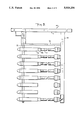
- FIG. 3 is a side view of a single modular UV lamp rack assembly in accordance with the invention.
- FIG. 4 is a top view of the assembly
- FIG. 5 separately illustrates the rod on which the swivel sleeves are supported
- FIG. 6 is a separate view of a single swivel sleeve and its end cap
- FIG. 7 is a sectional view of the upstream end of the lamp unit
- FIG. 8 is a sectional view of the downstream end of the lamp unit
- FIG. 9 is a section taken through the attachable coupler and the lamp socket therein.
- FIG. 10 illustrates the manner in which a lamp unit may be removed from the assembly.
- Module 10 includes a long horizontal hanger bar 11 having a square cross section formed of stainless steel or other high-strength, non-corrosive metal.
- a vertical metal rod 12 Depending from bar 11 at an upstream position is a vertical metal rod 12, and depending from bar 11 at a downstream position is a vertical metal conduit 15 having a rectangular cross section, conduit 15 serving as a waterproof passage for electrical cables.
- each sleeve Pivotally mounted on rod 12 at equi-spaced points therealong are metal sleeves 13, each swiveling in a horizontal plane.
- the leading end of each sleeve has a bullet-shaped cap 14 pressed therein, the cap being formed of synthetic plastic material, such as polyethylene or polypropylene.
- Mounted on conduit 15 in a direction facing sleeves 13 at corresponding equi-spaced points are detachable couplers 16, each housing a lamp socket.
- each sleeve 13 on upstream rod 12 and the corresponding coupler 16 on conduit 15 Extending between each sleeve 13 on upstream rod 12 and the corresponding coupler 16 on conduit 15 is a lamp unit 17 whose upstream end is slidably received in the rear section of the sleeve and whose downstream end is securely received in the detachable coupler 16 in a manner to be described later in greater detail.
- Each lamp unit 17 consists of an elongated tubular lamp capable of emitting ultraviolet ray energy at a wavelength having a sterilizing effect on the water irradiated thereby, the lamp being protectively housed within a quartz tube which is transparent to this radiation. Only the upstream end of the transparent tube is closed, the open downstream end received within coupler 16 being sealed thereby so that no water leaks into the tube.
- the UV lamp housed within the transparent tube is of the mercury vapor type having electrodes at either end. These electrodes are connected to terminal pins at the downstream end of the lamp, which pins plug into the lamp socket housed in the coupler.
- the lamp sockets are connected by wires running through conduit 15 to a connector at the top end of the conduit, the connector of each assembly being connected to a power control panel 18 by a cable 19.
- the bottom end of conduit 15, which is immersed in the stream, is closed.
- a power control panel 18 which is at a suitable central location is provided with ballast assemblies for the lamps, circuit breakers, control switches and relays, meters and lamp-intensity monitors.
- the present invention is not concerned with how the UV lamps are energized and controlled, for means known in the art may be used for this purpose.
- a modular UV lamp rack assembly having an array of lamp units in which each unit may readily be withdrawn and replaced without disturbing the other units.
- a group of modules 10 are installed in parallel relation in a channel 20 conducting a stream of water to be treated, the ends of hanger bars 11 of each module are nested in a series of parallel notches 21N formed in transverse bridge plates 21. These plates are positioned at upstream and downstream positions across this channel, only the upstream plate being shown in FIG. 2.
- modules 10 are maintained by notches 21N in the bridge plates in parallel relation. Because the hanger bars 11 have a square cross section matching that of notches 21N, the modules are thereby prevented from swinging. The ends of the hanger bar which extend beyond rod 12 and conduit 15 fit into the notches and provide handles for the assembly.
- a photo sensor may be installed on the module to detect the level of UV radiation emanating from the array of lamp units to produce a signal proportional thereto. This signal is transmitted to control panel 18 to indicate the UV intensity level and to produce an alarm signal when this level falls below a predetermined set point.
- Each module 10 is independent of the other modules in the group thereof, and because it is not bolted or otherwise attached to the bridge plates 21, it may be removed from the group for purposes of inspection and maintenance.
- the UV Module The UV Module:
- each module 10 includes an elongated metal deflector D whose interior surface has a specular finish which is mirror-like.
- the deflector is supported between upstream rod 12 and downstream conduit 15 above the uppermost lamp unit 17, and serves to reflect back into the water stream those UV rays emanating from the array of lamp units 17 which are upwardly directed.
- the deflector also functions to shield personnel looking down into the channel from ultraviolet rays which because of their intensity may be injurious to the eyes.
- deflectors D The width of deflectors D is such that the deflectors of adjacent modules almost touch, so as to block out UV radiation above the lamp rack. These deflectors also function as spacers between adjacent lamp racks and as stiffeners between the upstream and downstream legs of the racks.
- swivel sleeves 13 are pivotally supported adjacent their leading ends on vertical upstream rod 12 and are equi-spaced from each other by cylindrical metal spacers 22.
- the lower end of rod 12, which is an elongated bolt, is threaded to receive a nut 23.
- the bullet-shaped cap 14 which is formed of synthetic plastic material, includes a neck 14A of reduced diameter which fits frictionally into the leading end of metal sleeve 13.
- Each lamp unit 17, as shown separately in FIGS. 7 and 8, consists of a transparent, protective quartz tube 24 and an elongated UV lamp 25 coaxially supported therein by means of annular spacers 26. Quartz tube 24 functions as a temperature insulator or thermal barrier between the relatively cold water in which the unit is immersed and the hotter lamp surface.
- FIG. 7 shows the upstream end of the unit, and it will be seen that quartz tube 24 is closed at this end and that lamp 25 is provided at this end with an electrode 27. This electrode is connected by a fine wire (not shown) to a terminal pin at the downstream end of the lamp. It is to be noted that a space exists between the end of lamp 25 and the corresponding end of quartz tube 24 to allow clearance for the lamp to slide forward (upstream) when it is disconnected from its socket.
- the upstream end of lamp unit 17 is slidably received, as shown in FIG. 3, in the rear section of sleeve 13.
- the upstream end of the unit is surrounded with a thin collar 28 of elastomeric material, such as flexible foam plastic polyurethane or neoprene, the collar being bonded to the tube or shrink fit thereon.
- Collar 28 extends over the rounded end of quartz tube 24, the extension forming a bumper to protect this end from rod 12 when assembly 17 is inserted in sleeve 13.
- the quartz tube is open ended and the UV lamp which is coaxially supported therein is provided with terminal pins 29 which are connected to the lamp electrodes. While FIG. 8 shows four pins 29, only two of these pins are wired to electrodes, the other two serving only for mechanical stability. In practice, these extra two pins need not be used.
- detachable coupler 16 houses a lamp socket 30 into which terminal pins 29 are plugged.
- Lamp socket 30 is seated in a resilient grommet 34 through which extend the connecting wires for the lamp.
- a retaining sleeve 35 is press fitted into coupler 16 to mechanically hold socket 30 and grommet 34 in place.
- Grommet 34 functions to prevent leakage if there is a seal failure or breakage of the lamp, thereby preventing the liquid from contaminating adjacent lamps on the rack.
- an O-ring washer 36 which provides a seal when coupler 16, which is provided at its rear end with an externally threaded nipple 37, is screwed into conduit 15.
- Coupler 16 is provided with a locking nut 31 threadably received thereon. At the mouth of coupler 16 is a compressible O-ring 32 which engages the surface of the downstream end of the quartz tube to provide a liquid seal. When nut 31 is turned tight, it presses a washer 33 against O-ring 32.
- Each swivel sleeve 13 is normally at right angles to the supporting rod 12 of the rack.
- swivel sleeve 13 (see FIG. 10) is then swivelled out at an angle at which one can then slide the upstream end of lamp unit 17 into the rear section of the sleeve to a sufficient depth so that when the sleeve carrying the lamp unit is then swung back to its normal right angle position, the downstream end of the lamp unit clears the corresponding coupler 16.
- the lamp unit is then axially shifted in the downstream direction to enter coupler 16 whose nut 31 is then tightened to secure the plugged-in lamp unit in place.
- coupler nut 31 When it becomes necessary to remove the lamp unit from the rack to replace the UV lamp or its protective tube, coupler nut 31 is then loosened to permit an operator to shift the lamp unit axially in the upstream direction and to disengage the terminal pins of the lamp from its socket in the coupler.
- the upstream end of lamp unit 17 is axially advanced into a clearance zone Z in the intermediate section of sleeve 13 (see FIG. 3) to a degree sufficient to cause the downstream end of the lamp unit to clear coupler 16 so that, as shown in FIG. 10, the lamp unit may then be swivelled to a convenient angle permitting its withdrawal from its sleeve 13. The lamp unit may then be replaced and returned to the rack.
- ballasts for the UV lamps may be housed in conduit 15 which is enlarged to accommodate the ballasts.
- the ballasts may be housed in a waterproof enclosure located under deflector D and above the lamps on the rack.
- the lamp rack assembly is so placed that the water stream entering the channel impinges on the upstream or cap end of the assembly. In certain situations, it may be convenient or desirable to place the lamp rack assembly in the reverse direction with respect to the direction of flow.
Abstract
Description
Claims (14)
Priority Applications (2)
| Application Number | Priority Date | Filing Date | Title |
|---|---|---|---|
| US07/600,597 US5019256A (en) | 1990-10-19 | 1990-10-19 | Ultraviolet lamp rack assembly |
| CA002047084A CA2047084C (en) | 1990-10-19 | 1991-07-15 | Ultraviolet lamp rack assembly |
Applications Claiming Priority (1)
| Application Number | Priority Date | Filing Date | Title |
|---|---|---|---|
| US07/600,597 US5019256A (en) | 1990-10-19 | 1990-10-19 | Ultraviolet lamp rack assembly |
Publications (1)
| Publication Number | Publication Date |
|---|---|
| US5019256A true US5019256A (en) | 1991-05-28 |
Family
ID=24404240
Family Applications (1)
| Application Number | Title | Priority Date | Filing Date |
|---|---|---|---|
| US07/600,597 Expired - Fee Related US5019256A (en) | 1990-10-19 | 1990-10-19 | Ultraviolet lamp rack assembly |
Country Status (2)
| Country | Link |
|---|---|
| US (1) | US5019256A (en) |
| CA (1) | CA2047084C (en) |
Cited By (78)
| Publication number | Priority date | Publication date | Assignee | Title |
|---|---|---|---|---|
| US5124132A (en) * | 1991-06-20 | 1992-06-23 | Plasma Technics, Inc. | Corona discharge ozone generator |
| DE4119725A1 (en) * | 1991-06-16 | 1993-01-21 | Delta Uv Gmbh | UV irradiation equipment esp. for waste water treatment in open channel - in which transparent protective tube ends, through which the electrical leads pass, are held above water surface by floats |
| US5208461A (en) * | 1991-10-03 | 1993-05-04 | Simon Hydro-Aerobics, Inc. | Ultra-violet wastewater disinfection system |
| DE4220088A1 (en) * | 1992-06-19 | 1994-01-05 | Delta Uv Gmbh | Device for irradiating water in the free-level drain with UV light |
| FR2698865A1 (en) * | 1992-12-04 | 1994-06-10 | Infilco Degremont Inc | Ultraviolet disinfection module. |
| WO1994020208A1 (en) * | 1993-03-05 | 1994-09-15 | Trojan Technologies Inc. | Fluid treatment system and process |
| US5368826A (en) * | 1992-12-04 | 1994-11-29 | Infilco Degremont, Inc. | Control apparatus for fluid disinfection modules and systems |
| US5376281A (en) * | 1993-07-21 | 1994-12-27 | Safta; Eugen | Water purification system |
| US5428284A (en) * | 1990-06-30 | 1995-06-27 | Nippon Densan Corporation | Method of and circuit for starting sensorless motor |
| US5504335A (en) * | 1994-10-17 | 1996-04-02 | Trojan Technologies, Inc. | Fluid treatment device and method |
| US5503800A (en) * | 1994-03-10 | 1996-04-02 | Uv Systems Technology, Inc. | Ultra-violet sterilizing system for waste water |
| US5601786A (en) * | 1994-06-02 | 1997-02-11 | Monagan; Gerald C. | Air purifier |
| US5624573A (en) * | 1994-05-17 | 1997-04-29 | Wiesmann; Rudolf | Apparatus for the disinfection of a flowing liquid medium and a plant for the treatment of clarified sewage |
| US5660719A (en) * | 1994-12-23 | 1997-08-26 | Kurtz; Mark E. | Ultraviolet light apparatus for fluid purification |
| US5792433A (en) * | 1995-03-13 | 1998-08-11 | Photoscience Japan Corporation | Light irradiating device with easily replaceable light irradiating lamps |
| US5846437A (en) * | 1997-01-03 | 1998-12-08 | Trojan Technologies Inc. | Increasing turbulent mixing in a UV system |
| EP0893411A1 (en) * | 1997-07-22 | 1999-01-27 | Infilco Degremont, Inc. | Apparatus for improving UV dosage applied to fluids in open channel UV disinfection systems |
| KR100216903B1 (en) * | 1994-11-17 | 1999-09-01 | 전주범 | The fabrication method for optical projection system |
| US5997812A (en) | 1996-06-20 | 1999-12-07 | Coolant Treatment Systems, L.L.C. | Methods and apparatus for the application of combined fields to disinfect fluids |
| WO1999062567A1 (en) * | 1998-05-30 | 1999-12-09 | Hansa Metallwerke Ag | Circuit for operating a uv-lamp in a degerminating reactor |
| US6015229A (en) * | 1997-09-19 | 2000-01-18 | Calgon Carbon Corporation | Method and apparatus for improved mixing in fluids |
| US6083387A (en) * | 1996-06-20 | 2000-07-04 | Burnham Technologies Ltd. | Apparatus for the disinfection of fluids |
| USRE36896E (en) * | 1993-03-05 | 2000-10-03 | Trojan Technologies Inc. | Fluid treatment system and process |
| WO2000075080A1 (en) * | 1999-06-04 | 2000-12-14 | Henry Kozlowski | Apparatus for ultraviolet light treatment of fluids |
| EP1072558A1 (en) * | 1999-07-26 | 2001-01-31 | Photoscience Japan Corporation | Ultraviolet liquid treatment apparatus |
| US6215126B1 (en) * | 1998-09-03 | 2001-04-10 | Purifics Enviornmental Technologies, Inc. | Plug and method of manufacture |
| NL1013660C2 (en) * | 1999-11-24 | 2001-05-28 | Orben Advisors S A | Device suitable for treating liquids, especially contaminated water. |
| US6296775B1 (en) | 1998-11-09 | 2001-10-02 | Kenneth W. Moody | Apparatus and method for UV wastewater purification in septic tank systems |
| WO2002030827A1 (en) * | 2000-10-12 | 2002-04-18 | Photoscience Japan Corporation | Cooling of ballast in water purification apparatus |
| AU747728B2 (en) * | 1993-03-05 | 2002-05-23 | Trojan Technologies Inc. | Fluid treatment system and process |
| WO2002048050A2 (en) * | 2000-12-15 | 2002-06-20 | Trojan Technologies Inc. | Fluid treatment system and radiation source module for use therein |
| US6500312B2 (en) | 1998-12-30 | 2002-12-31 | Wedeco Ag | Device and method for UV-irradiation, especially for disinfecting, flowing liquids with reduced UV-transmission |
| US6507028B2 (en) | 1999-12-17 | 2003-01-14 | Trojan Technologies, Inc. | Radiation source module |
| US6565802B1 (en) | 1999-06-03 | 2003-05-20 | Baxter International Inc. | Apparatus, systems and methods for processing and treating a biological fluid with light |
| US6583422B2 (en) * | 2001-10-11 | 2003-06-24 | Atlantic Ultraviolet Corporation | Ultraviolet water purifier |
| US6613277B1 (en) | 1999-06-18 | 2003-09-02 | Gerald C. Monagan | Air purifier |
| US20030165398A1 (en) * | 1999-06-03 | 2003-09-04 | Waldo Jeffrey M. | Apparatus, systems and methods for processing and treating a biological fluid with light |
| WO2004000735A1 (en) | 2002-06-19 | 2003-12-31 | Trojan Technologies Inc. | Fluid treatment system and radiation source module for use therein |
| US20040061069A1 (en) * | 2002-09-26 | 2004-04-01 | Schalble Uwe D. | Fluid treatment system with UV sensor and intelligent driver |
| US20040211926A1 (en) * | 2000-01-28 | 2004-10-28 | Trojan Technologies Inc. | Radiation source module |
| US20050000365A1 (en) * | 2003-05-08 | 2005-01-06 | Roger Nelsen | System for purifying and removing contaminants from gaseous fluids |
| AU782018B2 (en) * | 1993-03-05 | 2005-06-30 | Trojan Technologies Inc. | Fluid treatment system and process |
| US20050175498A1 (en) * | 1997-09-17 | 2005-08-11 | Jerry Nelson | Method and apparatus for producing purified or ozone enriched air to remove contaminants from fluids |
| US20060192135A1 (en) * | 2003-03-27 | 2006-08-31 | Pierre Girodet | Ultraviolet radiation water disinfecting device |
| US20060222576A1 (en) * | 2003-08-13 | 2006-10-05 | Rudkowski Jan B | Device for the uv treatment of flowing fluids |
| WO2007094538A1 (en) * | 2006-02-16 | 2007-08-23 | Ecobase Co., Ltd | Purification apparatus using integrated pipes coated with photo-catalyst and purification system using the same |
| US20070251812A1 (en) * | 2006-03-27 | 2007-11-01 | Hayman John J Jr | Photocatalytic air treatment system and method |
| EP1979006A1 (en) * | 2005-12-21 | 2008-10-15 | Trojan Technologies Inc. | Fluid treatment system |
| WO2009076765A1 (en) * | 2007-12-14 | 2009-06-25 | Trojan Technologies | Radiation source assembly and fluid treatment system |
| WO2009115924A2 (en) * | 2008-03-21 | 2009-09-24 | Butters Brian E | End-to-end lamp assembly and method of manufacturing same |
| US20090280027A1 (en) * | 2006-03-27 | 2009-11-12 | Hayman Jr John J | Photocatalytic air treatment system and method |
| US20110062071A1 (en) * | 2003-09-05 | 2011-03-17 | Foret Plasma Labs, Llc | System for Treating Liquids with Wave Energy from an Electrical Arc |
| CN102115227A (en) * | 2009-12-31 | 2011-07-06 | 上海广茂达光艺科技股份有限公司 | Ultraviolet water body disinfection device of open channel type |
| CN102167420A (en) * | 2010-02-26 | 2011-08-31 | 上海广茂达光艺科技股份有限公司 | Open-channel type ultraviolet LED water body sterilizing device |
| EP2449575A1 (en) * | 2009-07-02 | 2012-05-09 | Trojan Technologies | Radiation source assembly |
| US20120118803A1 (en) * | 2009-03-27 | 2012-05-17 | Council Of Scientific & Industrial Reserarch | Manually operated continuous flow type driking water disinfector using concentrated solar radiation |
| US8603333B2 (en) | 2003-09-05 | 2013-12-10 | Foret Plasma Labs, Llc | Treatment of fluids with wave energy from a carbon arc |
| US8618522B2 (en) | 2011-07-22 | 2013-12-31 | Jerry L. McKinney | Flow through apparatus for UV disinfection of water |
| US20140008547A1 (en) * | 2010-10-04 | 2014-01-09 | Trojan Technologies | Sleeve holder assembly |
| US8734643B2 (en) | 2001-07-16 | 2014-05-27 | Foret Plasma Labs, Llc | Apparatus for treating a substance with wave energy from an electrical arc and a second source |
| US8734654B2 (en) | 2001-07-16 | 2014-05-27 | Foret Plasma Labs, Llc | Method for treating a substance with wave energy from an electrical arc and a second source |
| US8764978B2 (en) | 2001-07-16 | 2014-07-01 | Foret Plasma Labs, Llc | System for treating a substance with wave energy from an electrical arc and a second source |
| US8981250B2 (en) | 2001-07-16 | 2015-03-17 | Foret Plasma Labs, Llc | Apparatus for treating a substance with wave energy from plasma and an electrical Arc |
| US20150108372A1 (en) * | 2012-05-04 | 2015-04-23 | Xylem Water Solutions Herford GmbH | Uv water treatment plant with open channel |
| US20150115171A1 (en) * | 2012-05-04 | 2015-04-30 | Xylem Water Solutions Herford GmbH | Mixing device for open channel uv water treatment plants |
| US9127206B2 (en) | 2001-07-16 | 2015-09-08 | Foret Plasma Labs, Llc | Plasma whirl reactor apparatus and methods of use |
| US9499443B2 (en) | 2012-12-11 | 2016-11-22 | Foret Plasma Labs, Llc | Apparatus and method for sintering proppants |
| US20160347635A1 (en) * | 2014-01-21 | 2016-12-01 | Egon GRUBER | Device for disinfecting water using ozone and ultraviolet light |
| US9699879B2 (en) | 2013-03-12 | 2017-07-04 | Foret Plasma Labs, Llc | Apparatus and method for sintering proppants |
| US9771280B2 (en) | 2001-07-16 | 2017-09-26 | Foret Plasma Labs, Llc | System, method and apparatus for treating liquids with wave energy from plasma |
| US20180120031A1 (en) * | 2015-05-06 | 2018-05-03 | Koninklijke Philips N.V. | Assembly comprising an object having a surface which is intended to be exposed to water and an anti-fouling protector arrangement |
| WO2018170160A1 (en) * | 2017-03-14 | 2018-09-20 | Vioguard Inc. | Ultraviolet sanitizing device having a modular light assembly |
| JP2018146797A (en) * | 2017-03-06 | 2018-09-20 | ウシオ電機株式会社 | Light irradiation device |
| US10188119B2 (en) | 2001-07-16 | 2019-01-29 | Foret Plasma Labs, Llc | Method for treating a substance with wave energy from plasma and an electrical arc |
| US20190177994A1 (en) * | 2014-01-21 | 2019-06-13 | Egon GRUBER | Device for disinfecting water |
| US10330389B2 (en) * | 2014-12-12 | 2019-06-25 | Koninklijke Philips N.V. | Cooling apparatus for cooling a fluid by means of surface water |
| CN112543744A (en) * | 2018-08-02 | 2021-03-23 | 赛莱默欧洲有限责任公司 | Water disinfection system |
| US11679171B2 (en) | 2021-06-08 | 2023-06-20 | Steribin, LLC | Apparatus and method for disinfecting substances as they pass through a pipe |
Citations (9)
| Publication number | Priority date | Publication date | Assignee | Title |
|---|---|---|---|---|
| US2413704A (en) * | 1944-12-04 | 1947-01-07 | Art Metal Company | Ultraviolet sterilizer |
| US2935611A (en) * | 1957-07-26 | 1960-05-03 | Corn Products Co | Ultra-violet sterilization apparatus |
| US3948772A (en) * | 1975-04-16 | 1976-04-06 | Sidney Ellner | Split stream ultraviolet purification device |
| US4017734A (en) * | 1974-09-27 | 1977-04-12 | Ross Henry M | Water purification system utilizing ultraviolet radiation |
| US4482809A (en) * | 1981-11-30 | 1984-11-13 | Trojan Technologies Inc. | Ultraviolet fluid purifying device |
| US4757205A (en) * | 1986-06-10 | 1988-07-12 | Arlat Inc. | Ultraviolet water treatment apparatus |
| US4767932A (en) * | 1986-09-26 | 1988-08-30 | Ultraviolet Purification System, Inc. | Ultraviolet purification device |
| US4825083A (en) * | 1986-06-10 | 1989-04-25 | Arlat Inc. | Ultraviolet water treatment apparatus |
| US4872980A (en) * | 1988-09-13 | 1989-10-10 | Trojan Technologies, Inc. | Fluid purification device |
-
1990
- 1990-10-19 US US07/600,597 patent/US5019256A/en not_active Expired - Fee Related
-
1991
- 1991-07-15 CA CA002047084A patent/CA2047084C/en not_active Expired - Fee Related
Patent Citations (9)
| Publication number | Priority date | Publication date | Assignee | Title |
|---|---|---|---|---|
| US2413704A (en) * | 1944-12-04 | 1947-01-07 | Art Metal Company | Ultraviolet sterilizer |
| US2935611A (en) * | 1957-07-26 | 1960-05-03 | Corn Products Co | Ultra-violet sterilization apparatus |
| US4017734A (en) * | 1974-09-27 | 1977-04-12 | Ross Henry M | Water purification system utilizing ultraviolet radiation |
| US3948772A (en) * | 1975-04-16 | 1976-04-06 | Sidney Ellner | Split stream ultraviolet purification device |
| US4482809A (en) * | 1981-11-30 | 1984-11-13 | Trojan Technologies Inc. | Ultraviolet fluid purifying device |
| US4757205A (en) * | 1986-06-10 | 1988-07-12 | Arlat Inc. | Ultraviolet water treatment apparatus |
| US4825083A (en) * | 1986-06-10 | 1989-04-25 | Arlat Inc. | Ultraviolet water treatment apparatus |
| US4767932A (en) * | 1986-09-26 | 1988-08-30 | Ultraviolet Purification System, Inc. | Ultraviolet purification device |
| US4872980A (en) * | 1988-09-13 | 1989-10-10 | Trojan Technologies, Inc. | Fluid purification device |
Cited By (148)
| Publication number | Priority date | Publication date | Assignee | Title |
|---|---|---|---|---|
| US5428284A (en) * | 1990-06-30 | 1995-06-27 | Nippon Densan Corporation | Method of and circuit for starting sensorless motor |
| DE4119725A1 (en) * | 1991-06-16 | 1993-01-21 | Delta Uv Gmbh | UV irradiation equipment esp. for waste water treatment in open channel - in which transparent protective tube ends, through which the electrical leads pass, are held above water surface by floats |
| US5124132A (en) * | 1991-06-20 | 1992-06-23 | Plasma Technics, Inc. | Corona discharge ozone generator |
| US5208461A (en) * | 1991-10-03 | 1993-05-04 | Simon Hydro-Aerobics, Inc. | Ultra-violet wastewater disinfection system |
| DE4220088A1 (en) * | 1992-06-19 | 1994-01-05 | Delta Uv Gmbh | Device for irradiating water in the free-level drain with UV light |
| US5332388A (en) * | 1992-12-04 | 1994-07-26 | Infilco Degremont, Inc. | Ultraviolet disinfection module |
| ES2078154A2 (en) * | 1992-12-04 | 1995-12-01 | Infilco Degremont Inc | Ultraviolet disinfection module |
| US5368826A (en) * | 1992-12-04 | 1994-11-29 | Infilco Degremont, Inc. | Control apparatus for fluid disinfection modules and systems |
| FR2698865A1 (en) * | 1992-12-04 | 1994-06-10 | Infilco Degremont Inc | Ultraviolet disinfection module. |
| DE4321460C2 (en) * | 1992-12-04 | 2002-10-17 | Infilco Degremont Inc | Ultraviolet disinfection module |
| US5539210A (en) * | 1993-03-05 | 1996-07-23 | Trojan Technologies, Inc. | Radiation sensor with means to remove fouling materials |
| USRE36896E (en) * | 1993-03-05 | 2000-10-03 | Trojan Technologies Inc. | Fluid treatment system and process |
| KR100330268B1 (en) * | 1993-03-05 | 2002-08-08 | 트로잰 테크놀로지스 인코포레이티드 | Fluid treatment system and treatment method |
| WO1994020208A1 (en) * | 1993-03-05 | 1994-09-15 | Trojan Technologies Inc. | Fluid treatment system and process |
| JPH08509905A (en) * | 1993-03-05 | 1996-10-22 | トローヤン・テクノロジーズ・アイエヌシー | Fluid treatment system and method |
| US5590390A (en) * | 1993-03-05 | 1996-12-31 | Trojan Technologies Inc. | Fluid treatment system and process |
| US5418370A (en) * | 1993-03-05 | 1995-05-23 | Trojan Technologies, Inc. | Fluid treatment system and process |
| AU747728B2 (en) * | 1993-03-05 | 2002-05-23 | Trojan Technologies Inc. | Fluid treatment system and process |
| KR100418308B1 (en) * | 1993-03-05 | 2004-02-14 | 트로잰 테크놀로지스 인코포레이티드 | A radiation source module |
| AU782018B2 (en) * | 1993-03-05 | 2005-06-30 | Trojan Technologies Inc. | Fluid treatment system and process |
| US5376281A (en) * | 1993-07-21 | 1994-12-27 | Safta; Eugen | Water purification system |
| US5503800A (en) * | 1994-03-10 | 1996-04-02 | Uv Systems Technology, Inc. | Ultra-violet sterilizing system for waste water |
| US5624573A (en) * | 1994-05-17 | 1997-04-29 | Wiesmann; Rudolf | Apparatus for the disinfection of a flowing liquid medium and a plant for the treatment of clarified sewage |
| US5601786A (en) * | 1994-06-02 | 1997-02-11 | Monagan; Gerald C. | Air purifier |
| US5504335A (en) * | 1994-10-17 | 1996-04-02 | Trojan Technologies, Inc. | Fluid treatment device and method |
| KR100216903B1 (en) * | 1994-11-17 | 1999-09-01 | 전주범 | The fabrication method for optical projection system |
| US5660719A (en) * | 1994-12-23 | 1997-08-26 | Kurtz; Mark E. | Ultraviolet light apparatus for fluid purification |
| US5792433A (en) * | 1995-03-13 | 1998-08-11 | Photoscience Japan Corporation | Light irradiating device with easily replaceable light irradiating lamps |
| US5997812A (en) | 1996-06-20 | 1999-12-07 | Coolant Treatment Systems, L.L.C. | Methods and apparatus for the application of combined fields to disinfect fluids |
| US6083387A (en) * | 1996-06-20 | 2000-07-04 | Burnham Technologies Ltd. | Apparatus for the disinfection of fluids |
| US6224759B1 (en) | 1997-01-03 | 2001-05-01 | Trojan Technologies, Inc. | Increasing turbulent mixing in a UV system |
| US6126841A (en) * | 1997-01-03 | 2000-10-03 | Trojan Technologies Inc. | Increasing turbulent mixing in a UV system |
| US5846437A (en) * | 1997-01-03 | 1998-12-08 | Trojan Technologies Inc. | Increasing turbulent mixing in a UV system |
| US5952663A (en) * | 1997-07-22 | 1999-09-14 | Infilco Degremont, Inc. | Apparatus for improving UV dosage applied to fluids in open channel UV disinfection systems |
| EP0893411A1 (en) * | 1997-07-22 | 1999-01-27 | Infilco Degremont, Inc. | Apparatus for improving UV dosage applied to fluids in open channel UV disinfection systems |
| US20050175498A1 (en) * | 1997-09-17 | 2005-08-11 | Jerry Nelson | Method and apparatus for producing purified or ozone enriched air to remove contaminants from fluids |
| US6015229A (en) * | 1997-09-19 | 2000-01-18 | Calgon Carbon Corporation | Method and apparatus for improved mixing in fluids |
| US6420715B1 (en) * | 1997-09-19 | 2002-07-16 | Trojan Technologies, Inc. | Method and apparatus for improved mixing in fluids |
| WO1999062567A1 (en) * | 1998-05-30 | 1999-12-09 | Hansa Metallwerke Ag | Circuit for operating a uv-lamp in a degerminating reactor |
| US6215126B1 (en) * | 1998-09-03 | 2001-04-10 | Purifics Enviornmental Technologies, Inc. | Plug and method of manufacture |
| US6296775B1 (en) | 1998-11-09 | 2001-10-02 | Kenneth W. Moody | Apparatus and method for UV wastewater purification in septic tank systems |
| US6193939B1 (en) | 1998-11-10 | 2001-02-27 | Henry Kozlowski | Apparatus for ultraviolet light treatment of fluids |
| US6500312B2 (en) | 1998-12-30 | 2002-12-31 | Wedeco Ag | Device and method for UV-irradiation, especially for disinfecting, flowing liquids with reduced UV-transmission |
| AU761277B2 (en) * | 1998-12-30 | 2003-05-29 | Xylem Ip Holdings Llc | UV radiation device, especially for disinfecting liquids with reduced UV transmission |
| US6565757B1 (en) | 1998-12-30 | 2003-05-20 | Wedeco Ag | UV radiation device, especially for disinfecting liquids with reduced UV transmission |
| US20030165398A1 (en) * | 1999-06-03 | 2003-09-04 | Waldo Jeffrey M. | Apparatus, systems and methods for processing and treating a biological fluid with light |
| US7601298B2 (en) | 1999-06-03 | 2009-10-13 | Fenwal, Inc. | Method for processing and treating a biological fluid with light |
| US20050258109A1 (en) * | 1999-06-03 | 2005-11-24 | Hanley Kathleen A | Apparatus, systems and methods for processing and treating a biological fluid with light |
| US6986867B2 (en) | 1999-06-03 | 2006-01-17 | Baxter International Inc. | Apparatus, systems and methods for processing and treating a biological fluid with light |
| US7068361B2 (en) | 1999-06-03 | 2006-06-27 | Baxter International | Apparatus, systems and methods for processing and treating a biological fluid with light |
| US6565802B1 (en) | 1999-06-03 | 2003-05-20 | Baxter International Inc. | Apparatus, systems and methods for processing and treating a biological fluid with light |
| US7459695B2 (en) | 1999-06-03 | 2008-12-02 | Fenwal, Inc. | Apparatus, and systems for processing and treating a biological fluid with light |
| WO2000075080A1 (en) * | 1999-06-04 | 2000-12-14 | Henry Kozlowski | Apparatus for ultraviolet light treatment of fluids |
| AU767926B2 (en) * | 1999-06-04 | 2003-11-27 | Henry Kozlowski | Apparatus for ultraviolet light treatment of fluids |
| US6613277B1 (en) | 1999-06-18 | 2003-09-02 | Gerald C. Monagan | Air purifier |
| EP1072558A1 (en) * | 1999-07-26 | 2001-01-31 | Photoscience Japan Corporation | Ultraviolet liquid treatment apparatus |
| WO2001038231A1 (en) * | 1999-11-24 | 2001-05-31 | Orben Advisors S.A. | Device suitable for treating liquids, in particular contaminated water |
| US6783670B1 (en) | 1999-11-24 | 2004-08-31 | Orben Advisors S.A. | Device suitable for treating liquids, in particular contaminated water |
| NL1013660C2 (en) * | 1999-11-24 | 2001-05-28 | Orben Advisors S A | Device suitable for treating liquids, especially contaminated water. |
| US6674084B2 (en) | 1999-12-17 | 2004-01-06 | Trojan Technologies, Inc. | Radiation source module |
| EP1239888B1 (en) * | 1999-12-17 | 2009-03-18 | Trojan Technologies Inc. | Radiation source module |
| US6507028B2 (en) | 1999-12-17 | 2003-01-14 | Trojan Technologies, Inc. | Radiation source module |
| US20040211926A1 (en) * | 2000-01-28 | 2004-10-28 | Trojan Technologies Inc. | Radiation source module |
| US6984834B2 (en) * | 2000-01-28 | 2006-01-10 | Trojan Technologies Inc. | Radiation source module |
| WO2002030827A1 (en) * | 2000-10-12 | 2002-04-18 | Photoscience Japan Corporation | Cooling of ballast in water purification apparatus |
| WO2002048050A2 (en) * | 2000-12-15 | 2002-06-20 | Trojan Technologies Inc. | Fluid treatment system and radiation source module for use therein |
| US7390406B2 (en) | 2000-12-15 | 2008-06-24 | Trojan Technologies Inc. | Fluid treatment system and radiation sources module for use therein |
| WO2002048050A3 (en) * | 2000-12-15 | 2002-10-24 | Trojan Techn Inc | Fluid treatment system and radiation source module for use therein |
| US20020113021A1 (en) * | 2000-12-15 | 2002-08-22 | Trojan Technologies Inc. | Fluid treatment system and radiation sources module for use therein |
| US8764978B2 (en) | 2001-07-16 | 2014-07-01 | Foret Plasma Labs, Llc | System for treating a substance with wave energy from an electrical arc and a second source |
| US10188119B2 (en) | 2001-07-16 | 2019-01-29 | Foret Plasma Labs, Llc | Method for treating a substance with wave energy from plasma and an electrical arc |
| US8734654B2 (en) | 2001-07-16 | 2014-05-27 | Foret Plasma Labs, Llc | Method for treating a substance with wave energy from an electrical arc and a second source |
| US8981250B2 (en) | 2001-07-16 | 2015-03-17 | Foret Plasma Labs, Llc | Apparatus for treating a substance with wave energy from plasma and an electrical Arc |
| US9127206B2 (en) | 2001-07-16 | 2015-09-08 | Foret Plasma Labs, Llc | Plasma whirl reactor apparatus and methods of use |
| US9127205B2 (en) | 2001-07-16 | 2015-09-08 | Foret Plasma Labs, Llc | Plasma whirl reactor apparatus and methods of use |
| US9446371B2 (en) | 2001-07-16 | 2016-09-20 | Foret Plasma Labs, Llc | Method for treating a substance with wave energy from an electrical arc and a second source |
| US10368557B2 (en) | 2001-07-16 | 2019-08-06 | Foret Plasma Labs, Llc | Apparatus for treating a substance with wave energy from an electrical arc and a second source |
| US9771280B2 (en) | 2001-07-16 | 2017-09-26 | Foret Plasma Labs, Llc | System, method and apparatus for treating liquids with wave energy from plasma |
| US8734643B2 (en) | 2001-07-16 | 2014-05-27 | Foret Plasma Labs, Llc | Apparatus for treating a substance with wave energy from an electrical arc and a second source |
| US6583422B2 (en) * | 2001-10-11 | 2003-06-24 | Atlantic Ultraviolet Corporation | Ultraviolet water purifier |
| US7323694B2 (en) | 2002-06-19 | 2008-01-29 | Trojan Technologies Inc. | Fluid treatment system and radiation source module for use therein |
| US20040069954A1 (en) * | 2002-06-19 | 2004-04-15 | Trojan Technologies Inc. | Fluid treatment system and radiation sources module for use therein |
| CN100513322C (en) * | 2002-06-19 | 2009-07-15 | 特洛伊人技术公司 | Fluid treatment system and radiation source module for use therein |
| WO2004000735A1 (en) | 2002-06-19 | 2003-12-31 | Trojan Technologies Inc. | Fluid treatment system and radiation source module for use therein |
| US6956220B2 (en) | 2002-06-19 | 2005-10-18 | Trojan Technologies Inc. | Fluid treatment system and radiation sources module for use therein |
| US20060091326A1 (en) * | 2002-06-19 | 2006-05-04 | Trojan Technologies, Inc. | Fluid treatment system and radiation source module for use therein |
| US20040061069A1 (en) * | 2002-09-26 | 2004-04-01 | Schalble Uwe D. | Fluid treatment system with UV sensor and intelligent driver |
| US6972415B2 (en) | 2002-09-26 | 2005-12-06 | R-Can Environmental Inc. | Fluid treatment system with UV sensor and intelligent driver |
| US20060192135A1 (en) * | 2003-03-27 | 2006-08-31 | Pierre Girodet | Ultraviolet radiation water disinfecting device |
| US7317193B2 (en) * | 2003-03-27 | 2008-01-08 | Otv Sa | Ultraviolet radiation water disinfecting device |
| US20050000365A1 (en) * | 2003-05-08 | 2005-01-06 | Roger Nelsen | System for purifying and removing contaminants from gaseous fluids |
| US6939397B2 (en) * | 2003-05-08 | 2005-09-06 | Eco-Rx, Inc. | System for purifying and removing contaminants from gaseous fluids |
| US20060222576A1 (en) * | 2003-08-13 | 2006-10-05 | Rudkowski Jan B | Device for the uv treatment of flowing fluids |
| US7696490B2 (en) * | 2003-08-13 | 2010-04-13 | Wedeco Ag | Device for the UV treatment of flowing fluids |
| US8337709B2 (en) | 2003-09-05 | 2012-12-25 | Foret Plasma Labs, Llc | Method for treating liquids with wave energy from an electrical arc |
| US8641898B2 (en) | 2003-09-05 | 2014-02-04 | Foret Plasma Labs, Llc | Apparatus for treating liquids with wave energy from an electrical arc |
| US8110100B2 (en) * | 2003-09-05 | 2012-02-07 | Foret Plasma Labs, Llc | System for treating liquids with wave energy from an electrical arc |
| US9428409B2 (en) | 2003-09-05 | 2016-08-30 | Foret Plasma Labs, Llc | Kit for treating liquids with wave energy from an electrical arc |
| US20110062071A1 (en) * | 2003-09-05 | 2011-03-17 | Foret Plasma Labs, Llc | System for Treating Liquids with Wave Energy from an Electrical Arc |
| US9156715B2 (en) | 2003-09-05 | 2015-10-13 | Foret Plasma Labs, Llc | Apparatus for treating liquids with wave energy from an electrical arc |
| US8343342B2 (en) | 2003-09-05 | 2013-01-01 | Foret Plasma Labs, Llc | Apparatus for treating liquids with wave energy from an electrical arc |
| US8828241B2 (en) | 2003-09-05 | 2014-09-09 | Foret Plasma Labs, Llc | Method for treating liquids with wave energy from an electrical arc |
| US8597523B2 (en) | 2003-09-05 | 2013-12-03 | Foret Plasma Labs, Llc | Method for treating liquids with wave energy from an electrical arc |
| US8603333B2 (en) | 2003-09-05 | 2013-12-10 | Foret Plasma Labs, Llc | Treatment of fluids with wave energy from a carbon arc |
| US8613856B2 (en) | 2003-09-05 | 2013-12-24 | Foret Plasma Labs, Llc | Treatment of fluids with wave energy from a carbon arc |
| US8628660B2 (en) | 2003-09-05 | 2014-01-14 | Foret Plasma Labs, Llc | Treatment of fluids with wave energy from a carbon arc |
| EP1979006A4 (en) * | 2005-12-21 | 2011-05-25 | Trojan Techn Inc | Fluid treatment system |
| EP1979006A1 (en) * | 2005-12-21 | 2008-10-15 | Trojan Technologies Inc. | Fluid treatment system |
| WO2007094538A1 (en) * | 2006-02-16 | 2007-08-23 | Ecobase Co., Ltd | Purification apparatus using integrated pipes coated with photo-catalyst and purification system using the same |
| US20090280027A1 (en) * | 2006-03-27 | 2009-11-12 | Hayman Jr John J | Photocatalytic air treatment system and method |
| US20070251812A1 (en) * | 2006-03-27 | 2007-11-01 | Hayman John J Jr | Photocatalytic air treatment system and method |
| WO2009076765A1 (en) * | 2007-12-14 | 2009-06-25 | Trojan Technologies | Radiation source assembly and fluid treatment system |
| US20110006223A1 (en) * | 2007-12-14 | 2011-01-13 | Trojan Technologies | Radiation source assembly and fluid treatment system |
| AU2009227681B2 (en) * | 2008-03-21 | 2014-10-09 | Brian E. Butters | End-to-end lamp assembly and method of manufacturing same |
| WO2009115924A2 (en) * | 2008-03-21 | 2009-09-24 | Butters Brian E | End-to-end lamp assembly and method of manufacturing same |
| WO2009115924A3 (en) * | 2008-03-21 | 2011-06-16 | Butters Brian E | End-to-end lamp assembly and method of manufacturing same |
| US9156713B2 (en) * | 2009-03-27 | 2015-10-13 | Council Of Scientific & Industrial Research | Manually operated continuous flow type drinking water disinfector using concentrated solar radiation |
| US20120118803A1 (en) * | 2009-03-27 | 2012-05-17 | Council Of Scientific & Industrial Reserarch | Manually operated continuous flow type driking water disinfector using concentrated solar radiation |
| EP2449575A1 (en) * | 2009-07-02 | 2012-05-09 | Trojan Technologies | Radiation source assembly |
| EP2449575A4 (en) * | 2009-07-02 | 2015-01-07 | Trojan Techn Inc | Radiation source assembly |
| US9533060B2 (en) | 2009-07-02 | 2017-01-03 | Trojan Technologies Inc. | Radiation source assembly |
| CN102115227A (en) * | 2009-12-31 | 2011-07-06 | 上海广茂达光艺科技股份有限公司 | Ultraviolet water body disinfection device of open channel type |
| CN102167420A (en) * | 2010-02-26 | 2011-08-31 | 上海广茂达光艺科技股份有限公司 | Open-channel type ultraviolet LED water body sterilizing device |
| CN102167420B (en) * | 2010-02-26 | 2013-07-24 | 上海广茂达光艺科技股份有限公司 | Open-channel type ultraviolet LED water body sterilizing device |
| US20140008547A1 (en) * | 2010-10-04 | 2014-01-09 | Trojan Technologies | Sleeve holder assembly |
| US8866105B2 (en) * | 2010-10-04 | 2014-10-21 | Trojan Technologies | Sleeve holder assembly |
| US8618522B2 (en) | 2011-07-22 | 2013-12-31 | Jerry L. McKinney | Flow through apparatus for UV disinfection of water |
| US9126851B2 (en) * | 2012-05-04 | 2015-09-08 | Xylem Water Solutions Herford GmbH | UV water treatment plant with open channel |
| US20150108372A1 (en) * | 2012-05-04 | 2015-04-23 | Xylem Water Solutions Herford GmbH | Uv water treatment plant with open channel |
| US20150115171A1 (en) * | 2012-05-04 | 2015-04-30 | Xylem Water Solutions Herford GmbH | Mixing device for open channel uv water treatment plants |
| US9193609B2 (en) * | 2012-05-04 | 2015-11-24 | Xylem Water Solutions Herford GmbH | Mixing device for open channel UV water treatment plants |
| US10030195B2 (en) | 2012-12-11 | 2018-07-24 | Foret Plasma Labs, Llc | Apparatus and method for sintering proppants |
| US9499443B2 (en) | 2012-12-11 | 2016-11-22 | Foret Plasma Labs, Llc | Apparatus and method for sintering proppants |
| US9801266B2 (en) | 2013-03-12 | 2017-10-24 | Foret Plasma Labs, Llc | Apparatus and method for sintering proppants |
| US9699879B2 (en) | 2013-03-12 | 2017-07-04 | Foret Plasma Labs, Llc | Apparatus and method for sintering proppants |
| US20160347635A1 (en) * | 2014-01-21 | 2016-12-01 | Egon GRUBER | Device for disinfecting water using ozone and ultraviolet light |
| US20190177994A1 (en) * | 2014-01-21 | 2019-06-13 | Egon GRUBER | Device for disinfecting water |
| US11359397B2 (en) * | 2014-01-21 | 2022-06-14 | Egon GRUBER | Device for disinfecting water |
| US10330389B2 (en) * | 2014-12-12 | 2019-06-25 | Koninklijke Philips N.V. | Cooling apparatus for cooling a fluid by means of surface water |
| US20180120031A1 (en) * | 2015-05-06 | 2018-05-03 | Koninklijke Philips N.V. | Assembly comprising an object having a surface which is intended to be exposed to water and an anti-fouling protector arrangement |
| US10816269B2 (en) * | 2015-05-06 | 2020-10-27 | Koninklijke Philips N.V. | Assembly comprising an object having a surface which is intended to be exposed to water and an anti-fouling protector arrangement |
| JP2018146797A (en) * | 2017-03-06 | 2018-09-20 | ウシオ電機株式会社 | Light irradiation device |
| WO2018170160A1 (en) * | 2017-03-14 | 2018-09-20 | Vioguard Inc. | Ultraviolet sanitizing device having a modular light assembly |
| US10413625B2 (en) | 2017-03-14 | 2019-09-17 | Vioguard | Ultraviolet sanitizing device having a modular light assembly |
| US10682432B2 (en) | 2017-03-14 | 2020-06-16 | Vioguard Inc. | Modular light assembly for ultraviolet sanitizing device |
| US11191857B2 (en) | 2017-03-14 | 2021-12-07 | Vioguard Inc. | Modular light assembly for ultraviolet sanitizing device |
| CN112543744A (en) * | 2018-08-02 | 2021-03-23 | 赛莱默欧洲有限责任公司 | Water disinfection system |
| US11679171B2 (en) | 2021-06-08 | 2023-06-20 | Steribin, LLC | Apparatus and method for disinfecting substances as they pass through a pipe |
Also Published As
| Publication number | Publication date |
|---|---|
| CA2047084A1 (en) | 1992-04-20 |
| CA2047084C (en) | 2002-01-22 |
Similar Documents
| Publication | Publication Date | Title |
|---|---|---|
| US5019256A (en) | Ultraviolet lamp rack assembly | |
| US4482809A (en) | Ultraviolet fluid purifying device | |
| US4757205A (en) | Ultraviolet water treatment apparatus | |
| USRE34513E (en) | Ultraviolet liquid purification system | |
| US6193939B1 (en) | Apparatus for ultraviolet light treatment of fluids | |
| CA2099063C (en) | Control apparatus for fluid disinfection modules and systems | |
| US3462597A (en) | Ultraviolet fluid purifier having manually operable wiper means | |
| EP3111963B1 (en) | Fluid treatment system comprising elongate radiation source assemblies | |
| US6583422B2 (en) | Ultraviolet water purifier | |
| HU219100B (en) | Uv fluid treatment device and method | |
| US4825083A (en) | Ultraviolet water treatment apparatus | |
| US4302677A (en) | Control arrangement for fluid sterilizing apparatus | |
| CA2477030C (en) | Fluid treatment device | |
| CA2458969C (en) | Fluid treatment system | |
| US20100148094A1 (en) | Radiation source cartridge and module containing same | |
| US7550742B2 (en) | UV light redundancy system | |
| US5792433A (en) | Light irradiating device with easily replaceable light irradiating lamps | |
| KR20050089703A (en) | Tap of water purifier having sterilizing lamp | |
| US6830697B1 (en) | Fluid treatment system, radiation source assembly and radiation source module | |
| US7767978B1 (en) | Ultraviolet water treatment device | |
| US3366441A (en) | Ultraviolet system for control of algae and slime within humidity control and similar systems | |
| CA2383686C (en) | Fluid treatment system, radiation source assembly and radiation source module | |
| JPH0647593Y2 (en) | External illumination UV irradiation device |
Legal Events
| Date | Code | Title | Description |
|---|---|---|---|
| AS | Assignment |
Owner name: FISCHER & PORTER COMPANY, A DE CORP., PENNSYLVANIA Free format text: ASSIGNMENT OF ASSIGNORS INTEREST.;ASSIGNORS:IFILL, LEE;WALKER, ROBERT;WOLFE, STEVEN;AND OTHERS;REEL/FRAME:005478/0617 Effective date: 19901001 |
|
| AS | Assignment |
Owner name: BA BUSINESS CREDIT, INC., NEW YORK Free format text: ASSIGNMENT OF ASSIGNORS INTEREST.;ASSIGNOR:FISCHER & PORTER COMPANY;REEL/FRAME:006259/0280 Effective date: 19920914 |
|
| FPAY | Fee payment |
Year of fee payment: 4 |
|
| FEPP | Fee payment procedure |
Free format text: PAYOR NUMBER ASSIGNED (ORIGINAL EVENT CODE: ASPN); ENTITY STATUS OF PATENT OWNER: LARGE ENTITY |
|
| AS | Assignment |
Owner name: ELSAG BAILEY (CANADA), INC., CANADA Free format text: ASSIGNMENT OF ASSIGNORS INTEREST;ASSIGNOR:FISCHER & PORTER COMPANY;REEL/FRAME:008861/0012 Effective date: 19971210 |
|
| AS | Assignment |
Owner name: FISCHER & PORTER COMPANY, PENNSYLVANIA Free format text: TERMINATION AND RELEASE OF ASSIGNMENT OF SECURITY INTEREST;ASSIGNOR:BA BUSINESS CREDIT, INC.;REEL/FRAME:008955/0950 Effective date: 19980204 |
|
| REMI | Maintenance fee reminder mailed | ||
| AS | Assignment |
Owner name: TROJAN TECHNOLOGIES, INC., CANADA Free format text: ASSIGNMENT OF ASSIGNORS INTEREST;ASSIGNOR:ELSAG BAILEY (CANADA), INC.;REEL/FRAME:009817/0307 Effective date: 19971222 |
|
| LAPS | Lapse for failure to pay maintenance fees | ||
| FP | Lapsed due to failure to pay maintenance fee |
Effective date: 19990528 |
|
| STCH | Information on status: patent discontinuation |
Free format text: PATENT EXPIRED DUE TO NONPAYMENT OF MAINTENANCE FEES UNDER 37 CFR 1.362 |