US5044375A - Unitary intravascular defibrillating catheter with separate bipolar sensing - Google Patents
Unitary intravascular defibrillating catheter with separate bipolar sensing Download PDFInfo
- Publication number
- US5044375A US5044375A US07/447,908 US44790889A US5044375A US 5044375 A US5044375 A US 5044375A US 44790889 A US44790889 A US 44790889A US 5044375 A US5044375 A US 5044375A
- Authority
- US
- United States
- Prior art keywords
- cardioversion
- electrode
- sensing
- catheter
- catheter body
- Prior art date
- Legal status (The legal status is an assumption and is not a legal conclusion. Google has not performed a legal analysis and makes no representation as to the accuracy of the status listed.)
- Expired - Lifetime
Links
Images


Classifications
-
- A—HUMAN NECESSITIES
- A61—MEDICAL OR VETERINARY SCIENCE; HYGIENE
- A61N—ELECTROTHERAPY; MAGNETOTHERAPY; RADIATION THERAPY; ULTRASOUND THERAPY
- A61N1/00—Electrotherapy; Circuits therefor
- A61N1/18—Applying electric currents by contact electrodes
- A61N1/32—Applying electric currents by contact electrodes alternating or intermittent currents
- A61N1/38—Applying electric currents by contact electrodes alternating or intermittent currents for producing shock effects
- A61N1/39—Heart defibrillators
- A61N1/3918—Heart defibrillators characterised by shock pathway, e.g. by electrode configuration
-
- A—HUMAN NECESSITIES
- A61—MEDICAL OR VETERINARY SCIENCE; HYGIENE
- A61N—ELECTROTHERAPY; MAGNETOTHERAPY; RADIATION THERAPY; ULTRASOUND THERAPY
- A61N1/00—Electrotherapy; Circuits therefor
- A61N1/02—Details
- A61N1/04—Electrodes
- A61N1/05—Electrodes for implantation or insertion into the body, e.g. heart electrode
- A61N1/056—Transvascular endocardial electrode systems
Definitions
- This invention relates to body implantable medical devices, and more particularly to defibrillating catheters employing bipolar sensing.
- Heart disease is a major cause of deaths in the United States and in other industrial countries.
- Tachyarrythmias rapid disturbances in cardiac electrical activity
- Atrial tachyarrythmic conditions are not considered life threatening unless they lead to rapid ventricular disturbance.
- Cardioversion devices include implantable electronic stand-by defibrillators which, in response to the detection of an abnormally rapid cardiac rhythm, discharge sufficient energy through electrodes connected to the heart to de-polarize and restore the heart to normal cardiac rhythm.
- Cardioverting or defibrillation devices typically include means for monitoring heart activity as well as delivery of cardioversion energy.
- U.S. Pat. No. 3,942,536 (Mirowski et al) discloses an intravascular catheter with a cap electrode at the distal tip, a distal electrode including a plurality of rings near the tip, and a proximal electrode also consisting of a plurality of rings.
- the tip and distal electrodes are used to provide pacing pulses, while defibrillation pulses are provided using the distal and proximal electrodes.
- a probe is provided to sense pressure in the right ventricle, to initiate cardioversion upon sensing a pressure that does not exceed a predetermined threshold.
- U.S. Pat. No. 4,355,646 (Kallok et al) is directed to a transvenous defibrillating lead with one tip electrode and three additional, annular electrodes.
- the tip electrode and the most distal of the annular electrodes are placed in the right ventricle and used to measure impedance changes in the ventricle.
- Defibrillating pulses are delivered across all four of the electrodes.
- the sensing means (one or more electrodes) of the defibrillating device must be capable of quickly detecting abnormally high cardiac rhythm in order to trigger the defibrillation pulse.
- the sensing means preferably is able to confirm a successful defibrillation, i.e. a return to normal cardiac rhythm, as soon as possible after each defibrillation pulse. Otherwise, there is the danger of the device delivering an unnecessary and possibly harmful defibrillation pulse.
- the catheter includes three electrodes: a distal tip electrode, an intermediate spring electrode and a proximal spring electrode.
- the tip and intermediate electrodes are used in pacing and sensing, while the intermediate and proximal spring electrodes are used to deliver defibrillation pulses.
- Another object is to provide a unitary defibrillation catheter with sensing circuitry independent of the defibrillation circuitry and with increased spacing of sensing electrodes from the nearest defibrillation electrode, for more discrete and localized electrograms.
- Another object of the invention is to provide an implantable defibrillation device with a defibrillation pulse delivery system with electrodes and conductors suited for relatively high energy defibrillation, along with independent sensing circuitry including electrodes and conductors suited to sensing.
- Yet another object is to provide a unitary defibrillation catheter which simultaneously affords optimum spacing between bipolar sensing electrodes, between a pair of defibrillation electrodes, and between the most adjacent sensing and defibrillation electrodes.
- the device includes an elongate, flexible and dielectric catheter body having a proximal end region, a distal end region and a lumen means formed in the body from the proximal end region to the distal end region.
- the device has a cardioversion circuit including a cardioversion electrode means mounted on the catheter body proximally of the distal region, and a flexible conductor means connected to the cardioversion electrode means, for conducting electrical pulses between the cardioversion electrode means and the proximal end region, and a cardioversion connector means near the proximal end region for electrically coupling the conductor means with a cardioversion pulse generating means, thereby to deliver cardioversion pulses to the cardioversion electrode means.
- the device further includes a cardiac sensing circuit including a first sensing electrode mounted on the catheter body at the distal end region, a first sensing conductor means connected to the first sensing electrode for detecting electrical pulses between the first sensing electrode and the proximal end region, a second sensing electrode mounted on the catheter body at the distal end region proximally of the first sensing electrode and spaced apart from the first sensing electrode by a predetermined first distance, a second flexible sensing conductor means connected to the second sensing electrode for detecting electrical pulses between the second sensing electrode and the proximal end region, and a sensing connector means near the proximal end region for electrically coupling the first and second sensing conductor means with a pulse sensing means, thereby to utilize the first and second sensing electrodes as a bipolar pulse sensing pair independent of the cardioversion circuit.
- a cardiac sensing circuit including a first sensing electrode mounted on the catheter body at the distal end region, a first sensing conductor means connected to the first sensing electrode
- the first sensing electrode is a distal tip electrode at the distal end of the catheter body
- the second sensing electrode is a ring electrode surrounding the catheter body and spaced apart from the tip electrode a distance in the range of from one to twenty millimeters, preferably ten millimeters.
- the cardioversion means advantageously includes distal and proximal cardioversion electrodes in the form of flexible, electrically conductive coils.
- the conductor means includes a first cardioversion conductor coupled to the distal conversion electrode and a second cardioversion conductor coupled to the proximal electrode. Both cardioversion conductors are flexible and contained in the lumen means, with the cardioversion connector means then coupling both cardioversion conductors to the pulse generating means.
- Each of the proximal and distal cardioversion coils can have a length in the range of from 1 to 7.5 centimeters.
- the preferred spacing between the proximal sensing electrode or ring electrode, and the distal defibrillating electrode is at least one centimeter. This ensures that heart tissue proximate and between the sensing electrodes is effectively isolated from the tissue subject to the defibrillation pulse. As a result the device affords accurate R-wave sensing immediately after applying a defibrillation pulse, substantially eliminating the possibility of charging for and delivering unnecessary defibrillation pulses after the heart has returned to normal sinus rhythm.
- a further advantage of the present invention is that it permits selection of the distance between the defibrillating electrodes for a preferred positioning of the distal defibrillating electrode, e.g. in the right ventricle near the apex, and of the proximal defibrillating electrode, e.g. high in the right atrium or within the superior vena cava.
- Total electrical independence of the sensing system from the defibrillation circuit permits simultaneous optimum separation of the tip and ring electrodes, the ring electrode and distal defibrillating electrode, and the two defibrillating electrodes, an advantage not attainable when a single electrode is utilized for defibrillation pulsing and sensing.
- a further advantage of the present invention resides in the ability to tailor electrodes and conductors specifically for the sensing system, and to tailor other electrodes and conductors specifically for the defibrillation circuit.
- the relatively high currents and voltages involved in the defibrillation circuit require relatively large surface area electrodes to reduce impedance, and conductors formed of drawn brazed strand (DBS) wires or other highly conductive material.
- DBS drawn brazed strand
- Such catheter further allows selection of materials and component sizes customized to either sensing or cardioversion, for example multi-conductor tube (MCT) construction involving coaxial windings for defibrillation conductors, in combination with sensing conductors contained within a central lumen of the catheter.
- MCT multi-conductor tube
- FIG. 1 Another aspect of the present invention is a cardioversion and sensing system in which sensing electrodes are mounted on a sensing catheter for use in conjunction with a pair of cardioversion electrodes.
- the cardioversion electrodes may be provided as coils on a separate cardioversion catheter, as two separate patch electrodes, or as a single defibrillation coil in combination with a patch electrode.
- the electrodes are placed in the region of the heart, encompassing ventricular and atrial endocardial placement, intraparacardial or extraparacardial placement, vascular positioning, and in general within the thoracic cavity.
- the use of patch electrodes for cardioversion, alone or with a coil electrode affords a high degree of flexibility in electrode positioning.
- a catheter system provides sensing electrodes in complete isolation from a defibrillation pulse delivery system, for substantially immediate R-wave sensing following the application of each defibrillation pulse.
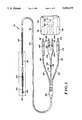
- FIG. 1 is a plan view of a unitary intravascular defibrillating catheter constructed in accordance with the present invention
- FIG. 2 is a sectional view of a portion of the catheter of FIG. 1;
- FIG. 3 is a sectional view illustrating the positioning of the catheter of FIG. 1 within the heart
- FIG. 4 is a sectional view of a portion of an alternative embodiment catheter constructed in accordance with the present invention.
- FIG. 5 is a plan view of another alternative embodiment of the invention comprising two leads separately implanted in the heart.
- FIG. 6 is a schematic view of yet another alternative embodiment using patch electrodes for defibrillation.
- FIGS. 7 and 8 show an alternative embodiment utilizing a bifurcated catheter.
- FIG. 1 a unitary intravascular defibrillation catheter 16 including an elongate and flexible catheter body 18 constructed of a dielectric material, for example silastic or polyurethane.
- Electrodes are mounted to the catheter body, including a distal tip electrode 20 at the distal end of the body, a bipolar ring electrode 22, a distal spring electrode 24 and a proximal spring electrode 26.
- Catheter body 18 further includes a reduced diameter distal tubing portion which supports the tip and ring electrodes, a proximal reduced diameter tubing portion 32 between spring electrodes 24 and 26, and a sheath portion 34 encompassing the majority of the catheter length.
- a reinforcing member 36 provides a junction for sheath 34 and three lengths of electrically insulative tubing 38, 40 and 42.
- Tubing 38 contains a conductor 44 provided for transmitting electrical signals from distal spring electrode 24 to a pin 46.
- An electrically insulative boot 48 surrounds pin 46 and tubing 44.
- a conductor 50 contained within insulative tubing 42 and sheath 34, electrically couples proximal spring electrode 26 and a pin 52, with pin 52 and tubing 42 being surrounded by an electrically insulative boot 54.
- a conductor 56 electrically couples ring electrode 22 with a pin 58
- a conductor 60 similarly couples tip electrode 20 with a pin 62.
- Pins 58 and 62 and conductors 56 and 60 are surrounded by an insulative plug 64 with boot portions 66 and 68.
- catheter 16 In use, catheter 16, particularly at plug 64 and boots 48 and 54, is electrically and mechanically coupled to a defibrillation control unit 70 including defibrillation pulse generating circuitry 72, represented schematically in FIG. 1.
- Unit 70 includes a pair of receptacles 76 and 78 for receiving pin 46 and boot 48, and pin 52 and boot 54, respectively, thus to electrically couple spring electrodes 24 and 26 with defibrillation pulse generating circuitry 72.
- Boots 48 and 54 which the conductors are contained and thus isolated from bodily fluids.
- Catheter 16 is inserted intravenously, for example into the subclavian vein or the cephalic vein, and progressively moved toward the heart until the distal end reaches a selected cardiac chamber. As illustrated in FIG. 3, catheter 16 preferably is inserted to position distal tip electrode 20 and ring electrode 22 in a right ventricle 106 of the heart 108, near the apex 110. Within the ranges for spacing and lengths discussed above, spring electrode 24 preferably is within the right ventricle when tip electrode 20 is positioned as described, with proximal spring electrode 26 located high in the right atrium 112 or in the superior vena cava 114.
- distal tip electrode 20, ring electrode 22, conductors 56 and 60 and sensing circuitry 80 cooperate to monitor electrical activity in the heart, in particular R-wave activity.
- FIG. 4 shows an alternative design catheter 120 with a solid platinum or titanium tip electrode 122 and an annular electrode 124 near the tip electrode for bipolar R-wave sensing.
- a central lumen 126 cf catheter 120 contains a pair of conductors 128 and 130 connected to tip electrode 122 and annular electrode 124, respectively.
- Conductor 128 includes a conductive single coil winding 132 surrounded by an insulative sheath 134 and exposed at its distal end for connection to the tip electrode.
- conductor 130 includes a coil winding 136 surrounded by an insulative sheath 138 and exposed for its connection to the annular electrode.
- Electrodes 122 and 124 are mounted on a fit tightly within their respective receptacles to provide a positive fluid seal.
- Defibrillation unit 70 further includes pulse or heart rate sensing circuitry represented schematically at 80.
- a pair of sensing receptacles 82 and 84 receive plug 64, to electrically couple distal tip electrode 20 and ring electrode 22 with the sensing circuitry, with the boot portions of the plug member again providing a fluid seal. Further details of defibrillation control unit 70 are not discussed herein as they are known in the art and not particularly germane to the present invention.
- the connection of pins 46, 52, 58 and 62 as described creates two independent electrical circuits a sensing circuit including tip electrode 20 and ring electrode 22, and a defibrillation circuit including spring electrodes 24 and 26.
- the sensing circuit monitors heart electrical activity, in particular to sense tachyarrythmias. In response to such sensing, the pulse generating circuit delivers a defibrillating pulse to the heart across spring electrodes 24 and 26.
- tip electrode 20 is constructed of one or more filaments, preferably a thin wire 86 of platinum or a platinum iridium alloy.
- the wire is stretched, then crumpled and packed against the distal end of catheter body 18.
- a screen 88 also of platinum or a platinum alloy, is fastened to the periphery of the catheter body distal end and maintains the crumpled wire in place.
- electrode 20 is highly porous, for example consisting of approximately twenty percent platinum alloy by volume, the remaining eighty percent being open to permit passage of bodily fluids through the tip electrode and to admit ingrowth of tissue, which ssists in anchoring the tip electrode after implant.
- Tip electrode performance may be further enhanced by surface treatment to micro texturize the tip, as disclosed in U.S. Pat. application Ser. No. 325,764 filed Mar. 20, 1989 and assigned to the assignee of this application. This treatment substantially increases the reactive surface area of the tip.
- Conductor 60 includes a single wound coil 90 formed of a nickel alloy or other electrically conductive material permitting flexure. The exposed distal end of coil 90 is electrically and mechanically coupled to distal tip electrode 20. The remainder of the coil is surrounded by a flexible, dielectric sheath 92. The remaining conductors are similarly constructed.
- Conductor 56 includes a single wound coil 94 surrounded by a sheath 96 and with its exposed distal end coupled to ring electrode 22.
- the ring electrode is constructed of platinum, a platinum iridium alloy or other appropriate electrically conductive and body compatible material.
- the outer surface area of the ring electrode exposed to bodily tissue and fluids is in the range of from ten to fifty square millimeters, and more preferably is about the same in effective surface area as the tip. If desired, ring electrode 22 car be subject to sputtering or other surface treatment to impart microporosity. For accurate R-wave sensing, ring electrode 22 must be spaced apart from tip electrode 20 in the range of from one to twenty millimeters, with a particularly preferred spacing between these electrodes being about ten millimeters.
- Distal spring electrode 24 can have a length of from 1 to 7.5 centimeters, and up to 15 centimeters if especially smooth. Preferably electrode 24 is 6 centimeters long, to provide a relatively large exposed surface area necessary for effective delivery of defibrillation pulses.
- Spring electrode 24 is spaced apart from ring electrode 22 a distance in the range of five to twenty millimeters, although generally a spacing of at least one centimeter is recommended to ensure that heart tissue used in sensing pulse rate, particularly tissue near ring electrode 22, is sufficiently distant from tissue affected by the defibrillation pulse to ensure a localized, isolated and therefore more accurate R-wave sensing.
- spring electrode 26 is constructed of an electrically conductive and bodily compatible material such as titanium or platinum.
- Proximal spring electrode 26 can have a length in the range of 1 to 7.5 centimeters, and is preferably 3.8 centimeters long. The spacing between proximal and distal spring electrodes 24 and 26 preferably is about eleven centimeters, although a spacing of from six to fourteen centimeters has been found satisfactory.
- Tubing sections 30 and 32, spring electrodes 24 and 26 and sheath 34 cooperate to define a central lumen 104 running the length of the catheter from the distal tip to reinforcing member 36.
- Conductors 44, 50, 56 and 60 all are contained within lumen 104.
- Proximally of reinforcing member 36 each of the conductors is contained within its corresponding one of tubing sections 38, 40 and 42.
- the proximal tubing sections sheath, spring electrodes, and distal tubing sections form a lumen means in dielectric and flexible distal tubing section 140 of catheter 120.
- Defibrillation pulses are applied through a pair of spring electrodes, a distal spring electrode 142 and a proximal spring electrode 144.
- the distal spring electrode is supported between a pair of fittings 146 and 148 at its opposite ends.
- Spring electrode 144 is similarly supported between a pair of fittings, one of which is shown at 150.
- multi-filament conductors 152 and 154 are connected to electrodes 122 and 124, respectively, and also are electrically coupled to a pulse generator, not shown.
- Each of conductors 152 and 154 includes a plurality of individual electrically conductive filaments arranged in parallel, helical paths about the center of catheter 120. More particularly, conductor 152 includes filaments 152a, 152b and 152c, embedded in a length of insulative tubing 156 and thus electrically isolated from one another. At their distal ends, however, filaments 152a-c are exposed for electrical coupling to distal spring electrode 142.
- conductor 154 includes filaments 154a, 154b and 154c. Through the majority of the length of conductor 154, the filaments are embedded in tubing 156 and thus are electrically isolated. The distal ends of the filaments are exposed near electrically conductive fitting 150, for electrical coupling to this fitting, illustrated as an alternative to a coupling of these filaments to spring electrode 144. Conductors 152 and 154 are laterally offset from one another over the entire length of tubing 156 and thus are electrically isolated from one another. The multi-filament construction of these conductors affords the desired flexibility in catheter 120 and the increased cross-sectional conductive area desired for handling high energy cardioversion pulses, while permitting the catheter diameter to remain relatively small. For a further explanation of the helically wound and isolated filament technique, reference is made to U.S. Pat. No. 4,559,951 (Dahl et al).
- FIG. 5 discloses yet another approach to separate sensing and defibrillating, employing a sensing catheter 160 and a defibrillation catheter 162, separately implantable within the right ventricle 164 of the heart 166.
- Sensing catheter 160 includes a tip electrode 168 and a ring electrode 170 near the distal tip but separated from the tube electrode by one to ten millimeters as previously explained.
- Defibrillation catheter 162 includes a distal tip with tines 174 to assist in positioning the catheter upon implant.
- Proximal and distal spring electrodes 176 and 178 are mounted to catheter tubing 180 as explained in connection with FIGS. 2 and 4.
- a pair of conductors one associated with each of spring electrodes 176 and 178, transmit defibrillation pulses to the spring electrodes.
- the conductors may be contained in a central lumen of the catheter, or alternatively helically wound as explained in connection with FIG. 4.
- the sensing and defibrillating conductors are coupled to pulse generating and heart rate sensing circuitry by plugs 184 and 182, respectively.
- a patch electrode 186 at least equal to spring electrodes 176 and 178 in surface area, is secured to myocardial tissue and used in combination with the spring electrodes or in lieu of one of the spring electrodes.
- the two-catheter system in FIG. 5 of course requires a greater degree of skill and effort for implantation.
- FIG. 6 schematically illustrates a system employing a sensing catheter 190 having a tip electrode 192 and a ring electrode 194 spaced apart from the tip electrode by one to ten millimeters.
- a pair of conductors in the catheter are connected at their distal ends to electrodes 192 and 194, respectively, and at their proximal ends to pins 196 and 198.
- the pins are plugged into a defibrillation control unit 200 similar to unit 70 described in connection with FIG. 1, to electrically couple the sensing electrodes to sensing circuitry in the control unit.
- the system further includes a pair of defibrillation electrodes in the form of patch electrodes 202 and 204, each of which is subcutaneously implanted in the thoracic region, e.g. secured to myocardial tissue.
- a conductor electrically couples patch electrode 202 with a proximal pin 206, and another conductor likewise couples patch electrode 204 to a proximal terminal pin 208.
- Pins 206 and 208 are plugged into control unit 200 to electrically couple the patch electrodes with a pulse generating circuit contained in the control unit.
- catheter 190 is provided solely for sensing and defibrillation is accomplished solely through the patch electrodes. Accordingly, this system is particularly useful in applications calling for maximum flexibility in the positioning of defibrillation electrodes, and in which a single catheter is preferred.
- FIGS. 7 and 8 illustrate another alternative, namely a bifurcated catheter 190 having a proximal spring cardioversion electrode 192 and a distal spring cardioversion electrode 194. Separate conductors are connected to spring electrodes 192 and 94 respectively, for transmitting cardioversion pulses between these electrodes.
- an insulative boot forms a junction 196.
- a first extension 198 distally of the junction, supports a helical coil 200 used in a known manner to secure extension 198, and thus the remainder of the lead, to endocardial tissue.
- a second extension 202 of the catheter is directed generally proximally of junction 196 but inclined relative to the remainder of the catheter.
- Two sensing electrodes including a tip electrode 204 and a ring electrode 206, are supported on extension 202 and constructed as previously described. Separate conductors are connected to tip electrode 204 and ring electrode 206 respectively, each for transmitting electrical pulses between its associated sensing electrode and the proximal end region of catheter 190.
- catheter 190 preferably is inserted to position the distal tip of extension 198 in the right ventricle 208 of the heart 210, at the apex 212.
- Coil 200 is secured to endocardial tissue at the apex and thus maintains catheter 190 in the desired position.
- distal spring electrode 194 preferably is within the right ventricle and proximal spring vena cava 216.
- Extension 202 of the catheter is inclined away from the remainder of catheter 190 toward the septum 218, preferably to position tip electrode 204 and ring electrode 206 against the septum along the outflow tract, again resulting in sensing remotely of the area subject to cardioversion pulses.
- these conductors be coils, with a known reverse winding technique used to negotiate the relatively sharp bend.
- the electrodes and conductors can be constructed as previously described.
- the R-wave sensing system is configured in complete electrical isolation from the cardioversion system, with a bipolar sensing electrode means interacting with endocardial tissue remote from tissue subject to the immediate electrical affects of cardioversion. Consequently post-shock sensing abnormalities encountered in connection with previous devices, particularly unitary catheters, are substantially eliminated. A more timely and accurate R-wave sensing is achieved, to substantially reduce the risk of generating unnecessary and possibly harmful cardioversion pulses after a return to normal sinus rhythm.
Abstract
Description
Claims (61)
Priority Applications (4)
| Application Number | Priority Date | Filing Date | Title |
|---|---|---|---|
| US07/447,908 US5044375A (en) | 1989-12-08 | 1989-12-08 | Unitary intravascular defibrillating catheter with separate bipolar sensing |
| EP91307243A EP0526671B1 (en) | 1989-12-08 | 1991-08-07 | Unitary intravascular defibrillating catheter with separate bipolar sensing |
| US07/753,115 US5269319A (en) | 1989-12-08 | 1991-08-30 | Unitary intravascular defibrillating catheter with bipolar sensing |
| US08/386,210 US5545205A (en) | 1989-12-08 | 1995-02-09 | Unitary intravascular defibrillating catheter with bipolar sensing |
Applications Claiming Priority (1)
| Application Number | Priority Date | Filing Date | Title |
|---|---|---|---|
| US07/447,908 US5044375A (en) | 1989-12-08 | 1989-12-08 | Unitary intravascular defibrillating catheter with separate bipolar sensing |
Related Child Applications (1)
| Application Number | Title | Priority Date | Filing Date |
|---|---|---|---|
| US07/753,115 Continuation-In-Part US5269319A (en) | 1989-12-08 | 1991-08-30 | Unitary intravascular defibrillating catheter with bipolar sensing |
Publications (1)
| Publication Number | Publication Date |
|---|---|
| US5044375A true US5044375A (en) | 1991-09-03 |
Family
ID=23778213
Family Applications (1)
| Application Number | Title | Priority Date | Filing Date |
|---|---|---|---|
| US07/447,908 Expired - Lifetime US5044375A (en) | 1989-12-08 | 1989-12-08 | Unitary intravascular defibrillating catheter with separate bipolar sensing |
Country Status (2)
| Country | Link |
|---|---|
| US (1) | US5044375A (en) |
| EP (1) | EP0526671B1 (en) |
Cited By (114)
| Publication number | Priority date | Publication date | Assignee | Title |
|---|---|---|---|---|
| US5144960A (en) * | 1991-03-20 | 1992-09-08 | Medtronic, Inc. | Transvenous defibrillation lead and method of use |
| WO1992020401A1 (en) * | 1991-04-10 | 1992-11-26 | British Technology Group Usa, Inc. | Defibrillator and demand pacer catheter and method |
| US5181526A (en) * | 1990-04-20 | 1993-01-26 | Tanaka Kikinzoku Kogyo K.K. | Electrode for human heart pacemaker |
| US5235977A (en) * | 1992-03-01 | 1993-08-17 | Siemens Aktiengesellschaft | Electrode arrangement for an implantable defibrillator/cardioverter |
| US5263977A (en) * | 1992-10-26 | 1993-11-23 | Angeion Corporation | Electrode spacing device |
| US5265623A (en) * | 1992-07-16 | 1993-11-30 | Angeion Corporation | Optimized field defibrillation catheter |
| US5269319A (en) * | 1989-12-08 | 1993-12-14 | Cardiac Pacemakers, Inc. | Unitary intravascular defibrillating catheter with bipolar sensing |
| WO1994011057A1 (en) * | 1992-11-16 | 1994-05-26 | Boaz Avitall | Catheter deflection control |
| US5336253A (en) * | 1993-02-23 | 1994-08-09 | Medtronic, Inc. | Pacing and cardioversion lead systems with shared lead conductors |
| US5342414A (en) * | 1993-07-01 | 1994-08-30 | Medtronic, Inc. | Transvenous defibrillation lead |
| US5366496A (en) * | 1993-04-01 | 1994-11-22 | Cardiac Pacemakers, Inc. | Subcutaneous shunted coil electrode |
| US5397342A (en) * | 1993-06-07 | 1995-03-14 | Cardiac Pacemakers, Inc. | Resilient structurally coupled and electrically independent electrodes |
| US5423865A (en) * | 1992-12-11 | 1995-06-13 | Siemens Elema Ab | Electrode system for a defibrillator |
| US5431683A (en) * | 1992-12-11 | 1995-07-11 | Pacesetter Ab | Electrode system for a defibrillator |
| US5454370A (en) * | 1993-12-03 | 1995-10-03 | Avitall; Boaz | Mapping and ablation electrode configuration |
| EP0677301A1 (en) | 1994-04-14 | 1995-10-18 | Pacesetter AB | Electrode apparatus with a variable distance between the electrodes |
| US5509411A (en) * | 1993-01-29 | 1996-04-23 | Cardima, Inc. | Intravascular sensing device |
| US5545203A (en) * | 1993-04-27 | 1996-08-13 | Pacesetter, Inc. | Crush resistant multi-conductor lead body |
| US5549109A (en) * | 1993-10-01 | 1996-08-27 | Target Therapeutics, Inc. | Sheathed multipolar catheter and multipolar guidewire for sensing cardiac electrical activity |
| WO1996036282A2 (en) * | 1995-05-15 | 1996-11-21 | Baxter International Inc. | Bipolar vascular sealing apparatus and methods |
| US5645064A (en) * | 1992-01-29 | 1997-07-08 | Cardima, Inc. | High resolution intravascular signal detection |
| US5645082A (en) * | 1993-01-29 | 1997-07-08 | Cardima, Inc. | Intravascular method and system for treating arrhythmia |
| US5674272A (en) * | 1995-06-05 | 1997-10-07 | Ventritex, Inc. | Crush resistant implantable lead |
| US5683447A (en) * | 1995-12-19 | 1997-11-04 | Ventritex, Inc. | Lead with septal defibrillation and pacing electrodes |
| US5749914A (en) * | 1989-01-06 | 1998-05-12 | Advanced Coronary Intervention | Catheter for obstructed stent |
| US5755764A (en) * | 1996-09-10 | 1998-05-26 | Sulzer Intermedics Inc. | Implantable cardiac stimulation catheter |
| US5788692A (en) * | 1995-06-30 | 1998-08-04 | Fidus Medical Technology Corporation | Mapping ablation catheter |
| WO1998051370A1 (en) * | 1997-05-12 | 1998-11-19 | Rtc, Inc. | Electrically conductive membrane suitable for medical uses |
| US5913887A (en) * | 1996-03-01 | 1999-06-22 | Cardiac Pacemakers, Inc. | Device for the transvenous cardioversion of atrial fibrillation or atrial flutter including three coil electrodes |
| US5916243A (en) * | 1992-11-24 | 1999-06-29 | Cardiac Pacemakers, Inc. | Implantable conformal coil patch electrode with multiple conductive elements for cardioversion and defibrillation |
| US5964793A (en) * | 1996-06-20 | 1999-10-12 | Rutten; Jean | Lead introducer with defibrillation electrode and method of atrial defibrillation |
| US5968086A (en) * | 1998-02-23 | 1999-10-19 | Medtronic, Inc. | Pacing and cardioversion lead systems with shared lead conductors |
| US6085119A (en) * | 1998-07-22 | 2000-07-04 | Cardiac Pacemakers, Inc. | Single pass endocardial lead for multi-site atrial pacing |
| US6088610A (en) * | 1993-01-29 | 2000-07-11 | Cardima, Inc. | Method and system for using multiple intravascular sensing devices to detect electrical activity |
| US6119043A (en) * | 1995-12-28 | 2000-09-12 | Cardiac Pacemakers, Inc. | Atrial and ventricular cardiac lead having a mechanical bias |
| US6152954A (en) * | 1998-07-22 | 2000-11-28 | Cardiac Pacemakers, Inc. | Single pass lead having retractable, actively attached electrode for pacing and sensing |
| US6181973B1 (en) | 1999-04-02 | 2001-01-30 | Claudio Ceron | Anchoring structure for implantable electrodes |
| US6212434B1 (en) | 1998-07-22 | 2001-04-03 | Cardiac Pacemakers, Inc. | Single pass lead system |
| US6219582B1 (en) * | 1998-12-30 | 2001-04-17 | Daig Corporation | Temporary atrial cardioversion catheter |
| US6256541B1 (en) | 1998-04-17 | 2001-07-03 | Cardiac Pacemakers, Inc. | Endocardial lead having defibrillation and sensing electrodes with septal anchoring |
| US6259954B1 (en) | 1999-02-18 | 2001-07-10 | Intermedics Inc. | Endocardial difibrillation lead with strain-relief coil connection |
| US6321122B1 (en) | 1998-07-22 | 2001-11-20 | Cardiac Pacemakers, Inc. | Single pass defibrillation/pacing lead with passively attached electrode for pacing and sensing |
| US6463334B1 (en) | 1998-11-02 | 2002-10-08 | Cardiac Pacemakers, Inc. | Extendable and retractable lead |
| US6501994B1 (en) | 1997-12-24 | 2002-12-31 | Cardiac Pacemakers, Inc. | High impedance electrode tip |
| US6574512B1 (en) * | 2000-08-28 | 2003-06-03 | Cardiac Pacemakers, Inc. | Lead system with main lead and transverse lead |
| US20040138710A1 (en) * | 1996-01-11 | 2004-07-15 | Itsik Shemer | Signal delivery through the right ventricular septum |
| US20040147994A1 (en) * | 2003-01-28 | 2004-07-29 | Cardiac Pacemakers, Inc. | Tachy lead system optimized for septal placement |
| US20040175893A1 (en) * | 2003-03-07 | 2004-09-09 | Applied Materials, Inc. | Apparatuses and methods for forming a substantially facet-free epitaxial film |
| US6802840B2 (en) | 2000-12-29 | 2004-10-12 | Afx, Inc. | Medical instrument positioning tool and method |
| US6976986B2 (en) | 2000-04-12 | 2005-12-20 | Afx, Inc. | Electrode arrangement for use in a medical instrument |
| US7027863B1 (en) | 1999-10-25 | 2006-04-11 | Impulse Dynamics N.V. | Device for cardiac therapy |
| US7033352B1 (en) | 2000-01-18 | 2006-04-25 | Afx, Inc. | Flexible ablation instrument |
| US7052491B2 (en) | 1998-10-23 | 2006-05-30 | Afx, Inc. | Vacuum-assisted securing apparatus for a microwave ablation instrument |
| US7062318B2 (en) | 1996-01-08 | 2006-06-13 | Impulse Dynamics (Israel) Ltd | Electrical muscle controller |
| US7082336B2 (en) | 2003-06-04 | 2006-07-25 | Synecor, Llc | Implantable intravascular device for defibrillation and/or pacing |
| US7099717B2 (en) | 2002-01-03 | 2006-08-29 | Afx Inc. | Catheter having improved steering |
| US7167748B2 (en) | 1996-01-08 | 2007-01-23 | Impulse Dynamics Nv | Electrical muscle controller |
| US20070027490A1 (en) * | 1996-09-16 | 2007-02-01 | Shlomo Ben-Haim | Fencing of Cardiac Muscles |
| US7192427B2 (en) | 2002-02-19 | 2007-03-20 | Afx, Inc. | Apparatus and method for assessing transmurality of a tissue ablation |
| US7226446B1 (en) | 1999-05-04 | 2007-06-05 | Dinesh Mody | Surgical microwave ablation assembly |
| US20070265673A1 (en) * | 2006-04-03 | 2007-11-15 | Terrance Ransbury | Flexible interconnect assembly for implantable medical devices |
| US7346399B2 (en) | 1999-05-28 | 2008-03-18 | Afx, Inc. | Monopole tip for ablation catheter |
| US20080208301A1 (en) * | 2007-02-26 | 2008-08-28 | Medtronic, Inc. | Implantable neurostimulator adapters |
| US20080269591A1 (en) * | 2006-06-08 | 2008-10-30 | Greatbatch Ltd. | Band stop filter employing a capacitor and an inductor tank circuit to enhance mri compatibility of active medical devices |
| US7460907B1 (en) | 1998-07-20 | 2008-12-02 | Impulse Dynamics N.V. | Pacing with hemodynamic enhancement |
| US7529589B2 (en) | 2003-06-04 | 2009-05-05 | Synecor Llc | Intravascular electrophysiological system and methods |
| US7617007B2 (en) | 2003-06-04 | 2009-11-10 | Synecor Llc | Method and apparatus for retaining medical implants within body vessels |
| US7647102B2 (en) | 1999-10-25 | 2010-01-12 | Impulse Dynamics N.V. | Cardiac contractility modulation device having anti-arrhythmic capabilities and method of operating thereof |
| US7678573B2 (en) | 1999-02-04 | 2010-03-16 | Pluristem Ltd. | Method of preparing a conditioned medium from a confluent stromal cell culture |
| US20100106227A1 (en) * | 2008-10-23 | 2010-04-29 | Pacesetter, Inc. | Systems and Methods for Disconnecting Electrodes of Leads of Implantable Medical Devices During an MRI to Reduce Lead Heating |
| US20100106214A1 (en) * | 2008-10-23 | 2010-04-29 | Pacesetter, Inc. | Systems and Methods for Exploiting the Tip or Ring Conductor of an Implantable Medical Device Lead During an MRI to Reduce Lead Heating and the Risks of MRI-Induced Stimulation |
| US7747335B2 (en) | 2003-12-12 | 2010-06-29 | Synecor Llc | Implantable medical device having pre-implant exoskeleton |
| US7774934B2 (en) | 1998-07-22 | 2010-08-17 | Cardiac Pacemakers, Inc. | Method for making a terminal connector |
| US7840262B2 (en) | 2003-03-10 | 2010-11-23 | Impulse Dynamics Nv | Apparatus and method for delivering electrical signals to modify gene expression in cardiac tissue |
| US7840264B1 (en) | 1996-08-19 | 2010-11-23 | Mr3 Medical, Llc | System and method for breaking reentry circuits by cooling cardiac tissue |
| US7843439B2 (en) | 2003-02-10 | 2010-11-30 | N-Trig Ltd. | Touch detection for a digitizer |
| US20110015713A1 (en) * | 2008-10-23 | 2011-01-20 | Pacesetter, Inc. | Systems and methods for reducing lead heating and the risks of mri-induced stimulation |
| US7908003B1 (en) | 1996-08-19 | 2011-03-15 | Mr3 Medical Llc | System and method for treating ischemia by improving cardiac efficiency |
| US7953481B1 (en) | 1999-10-25 | 2011-05-31 | Impulse Dynamics N.V. | Anti-arrhythmic device and a method of delivering anti-arrhythmic cardiac therapy |
| US8019421B2 (en) | 1999-03-05 | 2011-09-13 | Metacure Limited | Blood glucose level control |
| US8204606B2 (en) | 2002-12-19 | 2012-06-19 | Cardiac Pacemakers, Inc. | Implantable lead for septal placement of pacing electrodes |
| US8239045B2 (en) | 2003-06-04 | 2012-08-07 | Synecor Llc | Device and method for retaining a medical device within a vessel |
| US8244371B2 (en) | 2005-03-18 | 2012-08-14 | Metacure Limited | Pancreas lead |
| US8321013B2 (en) | 1996-01-08 | 2012-11-27 | Impulse Dynamics, N.V. | Electrical muscle controller and pacing with hemodynamic enhancement |
| US8346363B2 (en) | 1999-03-05 | 2013-01-01 | Metacure Limited | Blood glucose level control |
| US8352031B2 (en) | 2004-03-10 | 2013-01-08 | Impulse Dynamics Nv | Protein activity modification |
| US8548583B2 (en) | 2004-03-10 | 2013-10-01 | Impulse Dynamics Nv | Protein activity modification |
| US8666495B2 (en) | 1999-03-05 | 2014-03-04 | Metacure Limited | Gastrointestinal methods and apparatus for use in treating disorders and controlling blood sugar |
| US8700161B2 (en) | 1999-03-05 | 2014-04-15 | Metacure Limited | Blood glucose level control |
| US8792985B2 (en) | 2003-07-21 | 2014-07-29 | Metacure Limited | Gastrointestinal methods and apparatus for use in treating disorders and controlling blood sugar |
| US8825152B2 (en) | 1996-01-08 | 2014-09-02 | Impulse Dynamics, N.V. | Modulation of intracellular calcium concentration using non-excitatory electrical signals applied to the tissue |
| US8934975B2 (en) | 2010-02-01 | 2015-01-13 | Metacure Limited | Gastrointestinal electrical therapy |
| US9101765B2 (en) | 1999-03-05 | 2015-08-11 | Metacure Limited | Non-immediate effects of therapy |
| US9108066B2 (en) | 2008-03-20 | 2015-08-18 | Greatbatch Ltd. | Low impedance oxide resistant grounded capacitor for an AIMD |
| US9248283B2 (en) | 2001-04-13 | 2016-02-02 | Greatbatch Ltd. | Band stop filter comprising an inductive component disposed in a lead wire in series with an electrode |
| US9289618B1 (en) | 1996-01-08 | 2016-03-22 | Impulse Dynamics Nv | Electrical muscle controller |
| US9295828B2 (en) | 2001-04-13 | 2016-03-29 | Greatbatch Ltd. | Self-resonant inductor wound portion of an implantable lead for enhanced MRI compatibility of active implantable medical devices |
| US9427596B2 (en) | 2013-01-16 | 2016-08-30 | Greatbatch Ltd. | Low impedance oxide resistant grounded capacitor for an AIMD |
| US9713723B2 (en) | 1996-01-11 | 2017-07-25 | Impulse Dynamics Nv | Signal delivery through the right ventricular septum |
| US9821158B2 (en) | 2005-02-17 | 2017-11-21 | Metacure Limited | Non-immediate effects of therapy |
| USRE46699E1 (en) | 2013-01-16 | 2018-02-06 | Greatbatch Ltd. | Low impedance oxide resistant grounded capacitor for an AIMD |
| US9931503B2 (en) | 2003-03-10 | 2018-04-03 | Impulse Dynamics Nv | Protein activity modification |
| US9931514B2 (en) | 2013-06-30 | 2018-04-03 | Greatbatch Ltd. | Low impedance oxide resistant grounded capacitor for an AIMD |
| US10080889B2 (en) | 2009-03-19 | 2018-09-25 | Greatbatch Ltd. | Low inductance and low resistance hermetically sealed filtered feedthrough for an AIMD |
| US20190083174A1 (en) * | 2008-10-10 | 2019-03-21 | Intuitive Surgical Operations, Inc. | Integral electrode placement and connection systems |
| US10350421B2 (en) | 2013-06-30 | 2019-07-16 | Greatbatch Ltd. | Metallurgically bonded gold pocket pad for grounding an EMI filter to a hermetic terminal for an active implantable medical device |
| US10559409B2 (en) | 2017-01-06 | 2020-02-11 | Greatbatch Ltd. | Process for manufacturing a leadless feedthrough for an active implantable medical device |
| US10561837B2 (en) | 2011-03-01 | 2020-02-18 | Greatbatch Ltd. | Low equivalent series resistance RF filter for an active implantable medical device utilizing a ceramic reinforced metal composite filled via |
| US10589107B2 (en) | 2016-11-08 | 2020-03-17 | Greatbatch Ltd. | Circuit board mounted filtered feedthrough assembly having a composite conductive lead for an AIMD |
| US10905888B2 (en) | 2018-03-22 | 2021-02-02 | Greatbatch Ltd. | Electrical connection for an AIMD EMI filter utilizing an anisotropic conductive layer |
| US10912945B2 (en) | 2018-03-22 | 2021-02-09 | Greatbatch Ltd. | Hermetic terminal for an active implantable medical device having a feedthrough capacitor partially overhanging a ferrule for high effective capacitance area |
| US11198014B2 (en) | 2011-03-01 | 2021-12-14 | Greatbatch Ltd. | Hermetically sealed filtered feedthrough assembly having a capacitor with an oxide resistant electrical connection to an active implantable medical device housing |
| US11439815B2 (en) | 2003-03-10 | 2022-09-13 | Impulse Dynamics Nv | Protein activity modification |
| US11779768B2 (en) | 2004-03-10 | 2023-10-10 | Impulse Dynamics Nv | Protein activity modification |
Citations (16)
| Publication number | Priority date | Publication date | Assignee | Title |
|---|---|---|---|---|
| US3942536A (en) * | 1971-03-15 | 1976-03-09 | Mieczyslaw Mirowski | Cardioverting device having single intravascular catheter electrode system and method for its use |
| US4289144A (en) * | 1980-01-10 | 1981-09-15 | Medtronic, Inc. | A-V Sidearm lead |
| US4332259A (en) * | 1979-09-19 | 1982-06-01 | Mccorkle Jr Charles E | Intravenous channel cardiac electrode and lead assembly and method |
| US4355646A (en) * | 1980-11-26 | 1982-10-26 | Medtronic, Inc. | Transvenous defibrillating lead |
| US4393883A (en) * | 1980-11-03 | 1983-07-19 | Medtronic, Inc. | Single pass A-V lead |
| US4444195A (en) * | 1981-11-02 | 1984-04-24 | Cordis Corporation | Cardiac lead having multiple ring electrodes |
| US4481953A (en) * | 1981-11-12 | 1984-11-13 | Cordis Corporation | Endocardial lead having helically wound ribbon electrode |
| GB2157954A (en) * | 1984-05-04 | 1985-11-06 | Mirowski Mieczyslaw | Intravascular multiple electrode unitary catheter |
| US4559951A (en) * | 1982-11-29 | 1985-12-24 | Cardiac Pacemakers, Inc. | Catheter assembly |
| US4567901A (en) * | 1983-12-15 | 1986-02-04 | Cordis Corporation | Prebent ventricular/atrial cardiac pacing lead |
| US4567900A (en) * | 1984-06-04 | 1986-02-04 | Moore J Paul | Internal deployable defibrillator electrode |
| US4581953A (en) * | 1982-06-28 | 1986-04-15 | Teleflex Incorporated | Molded terminal with vibration dampener pocket |
| US4614192A (en) * | 1982-04-21 | 1986-09-30 | Mieczyslaw Mirowski | Implantable cardiac defibrillator employing bipolar sensing and telemetry means |
| US4662377A (en) * | 1985-11-07 | 1987-05-05 | Mieczyslaw Mirowski | Cardioverting method and apparatus utilizing catheter and patch electrodes |
| US4819662A (en) * | 1987-10-26 | 1989-04-11 | Cardiac Pacemakers, Inc. | Cardiac electrode with drug delivery capabilities |
| US4856524A (en) * | 1988-08-29 | 1989-08-15 | Intermedics, Inc. | A-V responsive rate adaptive pacemaker |
Family Cites Families (2)
| Publication number | Priority date | Publication date | Assignee | Title |
|---|---|---|---|---|
| FR2561929B1 (en) * | 1984-03-27 | 1989-02-03 | Atesys | IMPLANTED AUTOMATIC APPARATUS FOR VENTRICULAR DEFIBRILLATION |
| US4817608A (en) * | 1987-05-29 | 1989-04-04 | Mieczyslaw Mirowski | Cardioverting transvenous catheter/patch electrode system and method for its use |
-
1989
- 1989-12-08 US US07/447,908 patent/US5044375A/en not_active Expired - Lifetime
-
1991
- 1991-08-07 EP EP91307243A patent/EP0526671B1/en not_active Revoked
Patent Citations (18)
| Publication number | Priority date | Publication date | Assignee | Title |
|---|---|---|---|---|
| US3942536B1 (en) * | 1971-03-15 | 1987-03-24 | ||
| US3942536A (en) * | 1971-03-15 | 1976-03-09 | Mieczyslaw Mirowski | Cardioverting device having single intravascular catheter electrode system and method for its use |
| US4332259A (en) * | 1979-09-19 | 1982-06-01 | Mccorkle Jr Charles E | Intravenous channel cardiac electrode and lead assembly and method |
| US4289144A (en) * | 1980-01-10 | 1981-09-15 | Medtronic, Inc. | A-V Sidearm lead |
| US4393883A (en) * | 1980-11-03 | 1983-07-19 | Medtronic, Inc. | Single pass A-V lead |
| US4355646A (en) * | 1980-11-26 | 1982-10-26 | Medtronic, Inc. | Transvenous defibrillating lead |
| US4444195A (en) * | 1981-11-02 | 1984-04-24 | Cordis Corporation | Cardiac lead having multiple ring electrodes |
| US4481953A (en) * | 1981-11-12 | 1984-11-13 | Cordis Corporation | Endocardial lead having helically wound ribbon electrode |
| US4614192A (en) * | 1982-04-21 | 1986-09-30 | Mieczyslaw Mirowski | Implantable cardiac defibrillator employing bipolar sensing and telemetry means |
| US4581953A (en) * | 1982-06-28 | 1986-04-15 | Teleflex Incorporated | Molded terminal with vibration dampener pocket |
| US4559951A (en) * | 1982-11-29 | 1985-12-24 | Cardiac Pacemakers, Inc. | Catheter assembly |
| US4567901A (en) * | 1983-12-15 | 1986-02-04 | Cordis Corporation | Prebent ventricular/atrial cardiac pacing lead |
| US4603705A (en) * | 1984-05-04 | 1986-08-05 | Mieczyslaw Mirowski | Intravascular multiple electrode unitary catheter |
| GB2157954A (en) * | 1984-05-04 | 1985-11-06 | Mirowski Mieczyslaw | Intravascular multiple electrode unitary catheter |
| US4567900A (en) * | 1984-06-04 | 1986-02-04 | Moore J Paul | Internal deployable defibrillator electrode |
| US4662377A (en) * | 1985-11-07 | 1987-05-05 | Mieczyslaw Mirowski | Cardioverting method and apparatus utilizing catheter and patch electrodes |
| US4819662A (en) * | 1987-10-26 | 1989-04-11 | Cardiac Pacemakers, Inc. | Cardiac electrode with drug delivery capabilities |
| US4856524A (en) * | 1988-08-29 | 1989-08-15 | Intermedics, Inc. | A-V responsive rate adaptive pacemaker |
Non-Patent Citations (2)
| Title |
|---|
| Orthogonal Electrogram Sensing, Bruce N. Goldreyer et al, Pace, vol. 6, pp. 464 469 (Mar. Apr. 1983, Part III). * |
| Orthogonal Electrogram Sensing, Bruce N. Goldreyer et al, Pace, vol. 6, pp. 464-469 (Mar.-Apr. 1983, Part III). |
Cited By (174)
| Publication number | Priority date | Publication date | Assignee | Title |
|---|---|---|---|---|
| US5749914A (en) * | 1989-01-06 | 1998-05-12 | Advanced Coronary Intervention | Catheter for obstructed stent |
| US5269319A (en) * | 1989-12-08 | 1993-12-14 | Cardiac Pacemakers, Inc. | Unitary intravascular defibrillating catheter with bipolar sensing |
| US5545205A (en) * | 1989-12-08 | 1996-08-13 | Cardiac Pacemakers, Inc. | Unitary intravascular defibrillating catheter with bipolar sensing |
| US5181526A (en) * | 1990-04-20 | 1993-01-26 | Tanaka Kikinzoku Kogyo K.K. | Electrode for human heart pacemaker |
| WO1992016254A1 (en) * | 1991-03-20 | 1992-10-01 | Medtronic, Inc. | Transvenous defibrillation lead and method of use |
| AU650723B2 (en) * | 1991-03-20 | 1994-06-30 | Medtronic, Inc. | Transvenous defibrillation lead and method of use |
| US5144960A (en) * | 1991-03-20 | 1992-09-08 | Medtronic, Inc. | Transvenous defibrillation lead and method of use |
| WO1992020401A1 (en) * | 1991-04-10 | 1992-11-26 | British Technology Group Usa, Inc. | Defibrillator and demand pacer catheter and method |
| US5476502A (en) * | 1991-04-10 | 1995-12-19 | British Technology Group Usa Inc. | Defibrillator and demand pacer catheters and methods for using same |
| AU669670B2 (en) * | 1991-04-10 | 1996-06-20 | British Technology Group Usa, Inc. | Defibrillator and demand pacer catheter and method |
| US5374287A (en) * | 1991-04-10 | 1994-12-20 | British Technology Group Usa Inc. | Defibrillator and demand pacer catheters and methods for using same |
| US5645064A (en) * | 1992-01-29 | 1997-07-08 | Cardima, Inc. | High resolution intravascular signal detection |
| US5235977A (en) * | 1992-03-01 | 1993-08-17 | Siemens Aktiengesellschaft | Electrode arrangement for an implantable defibrillator/cardioverter |
| US5265623A (en) * | 1992-07-16 | 1993-11-30 | Angeion Corporation | Optimized field defibrillation catheter |
| US6398782B1 (en) | 1992-10-13 | 2002-06-04 | Edwards Lifesciences Corporation | Bipolar vascular sealing apparatus and methods |
| US5263977A (en) * | 1992-10-26 | 1993-11-23 | Angeion Corporation | Electrode spacing device |
| WO1994011057A1 (en) * | 1992-11-16 | 1994-05-26 | Boaz Avitall | Catheter deflection control |
| US5441483A (en) * | 1992-11-16 | 1995-08-15 | Avitall; Boaz | Catheter deflection control |
| US6038483A (en) * | 1992-11-24 | 2000-03-14 | Cardiac Pacemakers, Inc. | Implantable conformal coil patch electrode with multiple conductive elements for cardioversion and defibrillation |
| US6152955A (en) * | 1992-11-24 | 2000-11-28 | Cardiac Pacemakers, Inc. | Implantable conformal coil patch electrode with multiple conductive elements for cardioversion and defibrillation |
| US6026332A (en) * | 1992-11-24 | 2000-02-15 | Cardiac Pacemakers, Inc. | Implantable conformal coil patch electrode with multiple conductive elements for cardioversion and defibrillation |
| US5916243A (en) * | 1992-11-24 | 1999-06-29 | Cardiac Pacemakers, Inc. | Implantable conformal coil patch electrode with multiple conductive elements for cardioversion and defibrillation |
| US6032079A (en) * | 1992-11-24 | 2000-02-29 | Cardiac Pacemakers, Inc. | Implantable conformal coil electrode with multiple conductive elements for cardioversion and defibrillation |
| US5431683A (en) * | 1992-12-11 | 1995-07-11 | Pacesetter Ab | Electrode system for a defibrillator |
| US5423865A (en) * | 1992-12-11 | 1995-06-13 | Siemens Elema Ab | Electrode system for a defibrillator |
| US6141576A (en) * | 1993-01-29 | 2000-10-31 | Cardima, Inc. | Intravascular sensing device |
| US5881732A (en) * | 1993-01-29 | 1999-03-16 | Cardima, Inc. | Intravascular method and system for treating arrhythmia |
| US5960796A (en) * | 1993-01-29 | 1999-10-05 | Cardima, Inc. | Intravascular method and device for occluding a body lumen |
| US6088610A (en) * | 1993-01-29 | 2000-07-11 | Cardima, Inc. | Method and system for using multiple intravascular sensing devices to detect electrical activity |
| US5509411A (en) * | 1993-01-29 | 1996-04-23 | Cardima, Inc. | Intravascular sensing device |
| US5645082A (en) * | 1993-01-29 | 1997-07-08 | Cardima, Inc. | Intravascular method and system for treating arrhythmia |
| US5967978A (en) * | 1993-01-29 | 1999-10-19 | Cardima, Inc. | Intravascular sensing device |
| US5685322A (en) * | 1993-01-29 | 1997-11-11 | Cardima, Inc. | Intravascular system for treating arrhythmia |
| US5699796A (en) * | 1993-01-29 | 1997-12-23 | Cardima, Inc. | High resolution intravascular signal detection |
| US5706809A (en) * | 1993-01-29 | 1998-01-13 | Cardima, Inc. | Method and system for using multiple intravascular sensing devices to detect electrical activity |
| US5336253A (en) * | 1993-02-23 | 1994-08-09 | Medtronic, Inc. | Pacing and cardioversion lead systems with shared lead conductors |
| US5366496A (en) * | 1993-04-01 | 1994-11-22 | Cardiac Pacemakers, Inc. | Subcutaneous shunted coil electrode |
| US5545203A (en) * | 1993-04-27 | 1996-08-13 | Pacesetter, Inc. | Crush resistant multi-conductor lead body |
| US5397342A (en) * | 1993-06-07 | 1995-03-14 | Cardiac Pacemakers, Inc. | Resilient structurally coupled and electrically independent electrodes |
| US5342414A (en) * | 1993-07-01 | 1994-08-30 | Medtronic, Inc. | Transvenous defibrillation lead |
| US5549109A (en) * | 1993-10-01 | 1996-08-27 | Target Therapeutics, Inc. | Sheathed multipolar catheter and multipolar guidewire for sensing cardiac electrical activity |
| US5454370A (en) * | 1993-12-03 | 1995-10-03 | Avitall; Boaz | Mapping and ablation electrode configuration |
| US5711298A (en) * | 1994-01-27 | 1998-01-27 | Cardima, Inc. | High resolution intravascular signal detection |
| US5957842A (en) * | 1994-01-27 | 1999-09-28 | Cardima, Inc. | High resolution intravascular signal detection |
| US5578067A (en) * | 1994-04-14 | 1996-11-26 | Pacesetter Ab | Medical electrode system having a sleeve body and control element therefor for selectively positioning an exposed conductor area |
| EP0677301A1 (en) | 1994-04-14 | 1995-10-18 | Pacesetter AB | Electrode apparatus with a variable distance between the electrodes |
| WO1996036282A3 (en) * | 1995-05-15 | 1997-01-09 | Baxter Int | Bipolar vascular sealing apparatus and methods |
| WO1996036282A2 (en) * | 1995-05-15 | 1996-11-21 | Baxter International Inc. | Bipolar vascular sealing apparatus and methods |
| US5674272A (en) * | 1995-06-05 | 1997-10-07 | Ventritex, Inc. | Crush resistant implantable lead |
| US5788692A (en) * | 1995-06-30 | 1998-08-04 | Fidus Medical Technology Corporation | Mapping ablation catheter |
| US5683447A (en) * | 1995-12-19 | 1997-11-04 | Ventritex, Inc. | Lead with septal defibrillation and pacing electrodes |
| US6119043A (en) * | 1995-12-28 | 2000-09-12 | Cardiac Pacemakers, Inc. | Atrial and ventricular cardiac lead having a mechanical bias |
| US8301247B2 (en) | 1996-01-08 | 2012-10-30 | Impulse Dynamics, N.V. | Electrical muscle controller |
| US8311629B2 (en) | 1996-01-08 | 2012-11-13 | Impulse Dynamics, N.V. | Electrical muscle controller |
| US8260416B2 (en) | 1996-01-08 | 2012-09-04 | Impulse Dynamics, N.V. | Electrical muscle controller |
| US7167748B2 (en) | 1996-01-08 | 2007-01-23 | Impulse Dynamics Nv | Electrical muscle controller |
| US8306617B2 (en) | 1996-01-08 | 2012-11-06 | Impulse Dynamics N.V. | Electrical muscle controller |
| US8306616B2 (en) | 1996-01-08 | 2012-11-06 | Impulse Dynamics, N.V. | Electrical muscle controller |
| US9289618B1 (en) | 1996-01-08 | 2016-03-22 | Impulse Dynamics Nv | Electrical muscle controller |
| US7062318B2 (en) | 1996-01-08 | 2006-06-13 | Impulse Dynamics (Israel) Ltd | Electrical muscle controller |
| US8825152B2 (en) | 1996-01-08 | 2014-09-02 | Impulse Dynamics, N.V. | Modulation of intracellular calcium concentration using non-excitatory electrical signals applied to the tissue |
| US8321013B2 (en) | 1996-01-08 | 2012-11-27 | Impulse Dynamics, N.V. | Electrical muscle controller and pacing with hemodynamic enhancement |
| US9713723B2 (en) | 1996-01-11 | 2017-07-25 | Impulse Dynamics Nv | Signal delivery through the right ventricular septum |
| US7187970B2 (en) | 1996-01-11 | 2007-03-06 | Impulse Dynamics (Israel) Ltd | Excitable tissue control signal delivery to the right ventricular septum |
| US20040138710A1 (en) * | 1996-01-11 | 2004-07-15 | Itsik Shemer | Signal delivery through the right ventricular septum |
| US6741894B2 (en) | 1996-03-01 | 2004-05-25 | Cardiac Pacemakers, Inc. | Device for the transvenous cardioversion of atrial fibrillation or atrial flutter |
| US5913887A (en) * | 1996-03-01 | 1999-06-22 | Cardiac Pacemakers, Inc. | Device for the transvenous cardioversion of atrial fibrillation or atrial flutter including three coil electrodes |
| US6041256A (en) * | 1996-03-01 | 2000-03-21 | Cardiac Pacemakers, Inc. | Device for the transvenous cardioversion of atrial fibrillation or atrial flutter |
| US6438416B1 (en) | 1996-03-01 | 2002-08-20 | Cardiac Pacemakers, Inc. | Device for the transvenous cardioversion of atrial fibrillation or atrial flutter including three coil electrodes |
| US7366574B2 (en) | 1996-03-01 | 2008-04-29 | Cardiac Pacemakers, Inc. | Device for the transvenous cardioversion of atrial fibrillation or atrial flutter |
| US20040193240A1 (en) * | 1996-03-01 | 2004-09-30 | Cardiac Pacemakers, Inc. | Device for the transvenous cardioversion of atrial fibrillation or atrial flutter |
| US5964793A (en) * | 1996-06-20 | 1999-10-12 | Rutten; Jean | Lead introducer with defibrillation electrode and method of atrial defibrillation |
| US7840264B1 (en) | 1996-08-19 | 2010-11-23 | Mr3 Medical, Llc | System and method for breaking reentry circuits by cooling cardiac tissue |
| US7908003B1 (en) | 1996-08-19 | 2011-03-15 | Mr3 Medical Llc | System and method for treating ischemia by improving cardiac efficiency |
| US5755764A (en) * | 1996-09-10 | 1998-05-26 | Sulzer Intermedics Inc. | Implantable cardiac stimulation catheter |
| US20070027490A1 (en) * | 1996-09-16 | 2007-02-01 | Shlomo Ben-Haim | Fencing of Cardiac Muscles |
| WO1998051370A1 (en) * | 1997-05-12 | 1998-11-19 | Rtc, Inc. | Electrically conductive membrane suitable for medical uses |
| US6007488A (en) * | 1997-05-12 | 1999-12-28 | Rtc, Inc. | Medical probe including an electrically conductive membrane suitable for medical uses |
| US6501994B1 (en) | 1997-12-24 | 2002-12-31 | Cardiac Pacemakers, Inc. | High impedance electrode tip |
| US5968086A (en) * | 1998-02-23 | 1999-10-19 | Medtronic, Inc. | Pacing and cardioversion lead systems with shared lead conductors |
| US6256541B1 (en) | 1998-04-17 | 2001-07-03 | Cardiac Pacemakers, Inc. | Endocardial lead having defibrillation and sensing electrodes with septal anchoring |
| US7460907B1 (en) | 1998-07-20 | 2008-12-02 | Impulse Dynamics N.V. | Pacing with hemodynamic enhancement |
| US8285398B2 (en) | 1998-07-22 | 2012-10-09 | Cardiac Pacemakers, Inc. | Lead with terminal connector assembly |
| US6212434B1 (en) | 1998-07-22 | 2001-04-03 | Cardiac Pacemakers, Inc. | Single pass lead system |
| US8209035B2 (en) | 1998-07-22 | 2012-06-26 | Cardiac Pacemakers, Inc. | Extendable and retractable lead having a snap-fit terminal connector |
| US6152954A (en) * | 1998-07-22 | 2000-11-28 | Cardiac Pacemakers, Inc. | Single pass lead having retractable, actively attached electrode for pacing and sensing |
| US6321122B1 (en) | 1998-07-22 | 2001-11-20 | Cardiac Pacemakers, Inc. | Single pass defibrillation/pacing lead with passively attached electrode for pacing and sensing |
| US7774934B2 (en) | 1998-07-22 | 2010-08-17 | Cardiac Pacemakers, Inc. | Method for making a terminal connector |
| US6345204B1 (en) | 1998-07-22 | 2002-02-05 | Cardiac Pacemakers, Inc. | Single pass lead having retractable, actively attached electrode for pacing and sensing |
| US6505082B1 (en) | 1998-07-22 | 2003-01-07 | Cardiac Pacemakers, Inc. | Single pass lead system |
| US6085119A (en) * | 1998-07-22 | 2000-07-04 | Cardiac Pacemakers, Inc. | Single pass endocardial lead for multi-site atrial pacing |
| US7387627B2 (en) | 1998-10-23 | 2008-06-17 | Maquet Cardiovascular Llc | Vacuum-assisted securing apparatus for a microwave ablation instrument |
| US7052491B2 (en) | 1998-10-23 | 2006-05-30 | Afx, Inc. | Vacuum-assisted securing apparatus for a microwave ablation instrument |
| US7115126B2 (en) | 1998-10-23 | 2006-10-03 | Afx Inc. | Directional microwave ablation instrument with off-set energy delivery portion |
| US6463334B1 (en) | 1998-11-02 | 2002-10-08 | Cardiac Pacemakers, Inc. | Extendable and retractable lead |
| US6219582B1 (en) * | 1998-12-30 | 2001-04-17 | Daig Corporation | Temporary atrial cardioversion catheter |
| US7678573B2 (en) | 1999-02-04 | 2010-03-16 | Pluristem Ltd. | Method of preparing a conditioned medium from a confluent stromal cell culture |
| US6259954B1 (en) | 1999-02-18 | 2001-07-10 | Intermedics Inc. | Endocardial difibrillation lead with strain-relief coil connection |
| US8019421B2 (en) | 1999-03-05 | 2011-09-13 | Metacure Limited | Blood glucose level control |
| US8346363B2 (en) | 1999-03-05 | 2013-01-01 | Metacure Limited | Blood glucose level control |
| US8666495B2 (en) | 1999-03-05 | 2014-03-04 | Metacure Limited | Gastrointestinal methods and apparatus for use in treating disorders and controlling blood sugar |
| US8700161B2 (en) | 1999-03-05 | 2014-04-15 | Metacure Limited | Blood glucose level control |
| US9101765B2 (en) | 1999-03-05 | 2015-08-11 | Metacure Limited | Non-immediate effects of therapy |
| US6181973B1 (en) | 1999-04-02 | 2001-01-30 | Claudio Ceron | Anchoring structure for implantable electrodes |
| US7226446B1 (en) | 1999-05-04 | 2007-06-05 | Dinesh Mody | Surgical microwave ablation assembly |
| US7346399B2 (en) | 1999-05-28 | 2008-03-18 | Afx, Inc. | Monopole tip for ablation catheter |
| US7027863B1 (en) | 1999-10-25 | 2006-04-11 | Impulse Dynamics N.V. | Device for cardiac therapy |
| US7953481B1 (en) | 1999-10-25 | 2011-05-31 | Impulse Dynamics N.V. | Anti-arrhythmic device and a method of delivering anti-arrhythmic cardiac therapy |
| US7647102B2 (en) | 1999-10-25 | 2010-01-12 | Impulse Dynamics N.V. | Cardiac contractility modulation device having anti-arrhythmic capabilities and method of operating thereof |
| US7301131B2 (en) | 2000-01-18 | 2007-11-27 | Afx, Inc. | Microwave ablation instrument with flexible antenna assembly and method |
| US7033352B1 (en) | 2000-01-18 | 2006-04-25 | Afx, Inc. | Flexible ablation instrument |
| US7156841B2 (en) | 2000-04-12 | 2007-01-02 | Afx, Inc. | Electrode arrangement for use in a medical instrument |
| US6976986B2 (en) | 2000-04-12 | 2005-12-20 | Afx, Inc. | Electrode arrangement for use in a medical instrument |
| US6871101B2 (en) | 2000-08-28 | 2005-03-22 | Cardiac Pacemakers, Inc. | Lead system with sleeve for passing a lead |
| US6574512B1 (en) * | 2000-08-28 | 2003-06-03 | Cardiac Pacemakers, Inc. | Lead system with main lead and transverse lead |
| US7303560B2 (en) | 2000-12-29 | 2007-12-04 | Afx, Inc. | Method of positioning a medical instrument |
| US6802840B2 (en) | 2000-12-29 | 2004-10-12 | Afx, Inc. | Medical instrument positioning tool and method |
| US9295828B2 (en) | 2001-04-13 | 2016-03-29 | Greatbatch Ltd. | Self-resonant inductor wound portion of an implantable lead for enhanced MRI compatibility of active implantable medical devices |
| US9248283B2 (en) | 2001-04-13 | 2016-02-02 | Greatbatch Ltd. | Band stop filter comprising an inductive component disposed in a lead wire in series with an electrode |
| US7099717B2 (en) | 2002-01-03 | 2006-08-29 | Afx Inc. | Catheter having improved steering |
| US7192427B2 (en) | 2002-02-19 | 2007-03-20 | Afx, Inc. | Apparatus and method for assessing transmurality of a tissue ablation |
| US8204606B2 (en) | 2002-12-19 | 2012-06-19 | Cardiac Pacemakers, Inc. | Implantable lead for septal placement of pacing electrodes |
| US20040147994A1 (en) * | 2003-01-28 | 2004-07-29 | Cardiac Pacemakers, Inc. | Tachy lead system optimized for septal placement |
| US7843439B2 (en) | 2003-02-10 | 2010-11-30 | N-Trig Ltd. | Touch detection for a digitizer |
| US8228311B2 (en) | 2003-02-10 | 2012-07-24 | N-Trig Ltd. | Touch detection for a digitizer |
| US20040175893A1 (en) * | 2003-03-07 | 2004-09-09 | Applied Materials, Inc. | Apparatuses and methods for forming a substantially facet-free epitaxial film |
| US9931503B2 (en) | 2003-03-10 | 2018-04-03 | Impulse Dynamics Nv | Protein activity modification |
| US7840262B2 (en) | 2003-03-10 | 2010-11-23 | Impulse Dynamics Nv | Apparatus and method for delivering electrical signals to modify gene expression in cardiac tissue |
| US8326416B2 (en) | 2003-03-10 | 2012-12-04 | Impulse Dynamics Nv | Apparatus and method for delivering electrical signals to modify gene expression in cardiac tissue |
| US11439815B2 (en) | 2003-03-10 | 2022-09-13 | Impulse Dynamics Nv | Protein activity modification |
| US8239045B2 (en) | 2003-06-04 | 2012-08-07 | Synecor Llc | Device and method for retaining a medical device within a vessel |
| US7734343B2 (en) | 2003-06-04 | 2010-06-08 | Synecor, Llc | Implantable intravascular device for defibrillation and/or pacing |
| US7617007B2 (en) | 2003-06-04 | 2009-11-10 | Synecor Llc | Method and apparatus for retaining medical implants within body vessels |
| US7899554B2 (en) | 2003-06-04 | 2011-03-01 | Synecor Llc | Intravascular System and Method |
| US7529589B2 (en) | 2003-06-04 | 2009-05-05 | Synecor Llc | Intravascular electrophysiological system and methods |
| US7840282B2 (en) | 2003-06-04 | 2010-11-23 | Synecor Llc | Method and apparatus for retaining medical implants within body vessels |
| US7082336B2 (en) | 2003-06-04 | 2006-07-25 | Synecor, Llc | Implantable intravascular device for defibrillation and/or pacing |
| US8792985B2 (en) | 2003-07-21 | 2014-07-29 | Metacure Limited | Gastrointestinal methods and apparatus for use in treating disorders and controlling blood sugar |
| US7747335B2 (en) | 2003-12-12 | 2010-06-29 | Synecor Llc | Implantable medical device having pre-implant exoskeleton |
| US8352031B2 (en) | 2004-03-10 | 2013-01-08 | Impulse Dynamics Nv | Protein activity modification |
| US8548583B2 (en) | 2004-03-10 | 2013-10-01 | Impulse Dynamics Nv | Protein activity modification |
| US11779768B2 (en) | 2004-03-10 | 2023-10-10 | Impulse Dynamics Nv | Protein activity modification |
| US10352948B2 (en) | 2004-03-10 | 2019-07-16 | Impulse Dynamics Nv | Protein activity modification |
| US9821158B2 (en) | 2005-02-17 | 2017-11-21 | Metacure Limited | Non-immediate effects of therapy |
| US8244371B2 (en) | 2005-03-18 | 2012-08-14 | Metacure Limited | Pancreas lead |
| US20070265673A1 (en) * | 2006-04-03 | 2007-11-15 | Terrance Ransbury | Flexible interconnect assembly for implantable medical devices |
| US20080269591A1 (en) * | 2006-06-08 | 2008-10-30 | Greatbatch Ltd. | Band stop filter employing a capacitor and an inductor tank circuit to enhance mri compatibility of active medical devices |
| US8897887B2 (en) | 2006-06-08 | 2014-11-25 | Greatbatch Ltd. | Band stop filter employing a capacitor and an inductor tank circuit to enhance MRI compatibility of active medical devices |
| US7736192B2 (en) | 2007-02-26 | 2010-06-15 | Medtronic, Inc. | Implantable neurostimulator adapters |
| US7594828B2 (en) * | 2007-02-26 | 2009-09-29 | Medtronic, Inc. | Implantable neurostimulator adapters |
| US20090306751A1 (en) * | 2007-02-26 | 2009-12-10 | Medtronic, Inc. | Implantable neurostimulator adapters |
| US20080208301A1 (en) * | 2007-02-26 | 2008-08-28 | Medtronic, Inc. | Implantable neurostimulator adapters |
| US9108066B2 (en) | 2008-03-20 | 2015-08-18 | Greatbatch Ltd. | Low impedance oxide resistant grounded capacitor for an AIMD |
| US20190083174A1 (en) * | 2008-10-10 | 2019-03-21 | Intuitive Surgical Operations, Inc. | Integral electrode placement and connection systems |
| US11950838B2 (en) * | 2008-10-10 | 2024-04-09 | Intuitive Surgical Operations, Inc. | Integral electrode placement and connection systems |
| US20100106214A1 (en) * | 2008-10-23 | 2010-04-29 | Pacesetter, Inc. | Systems and Methods for Exploiting the Tip or Ring Conductor of an Implantable Medical Device Lead During an MRI to Reduce Lead Heating and the Risks of MRI-Induced Stimulation |
| US20100106227A1 (en) * | 2008-10-23 | 2010-04-29 | Pacesetter, Inc. | Systems and Methods for Disconnecting Electrodes of Leads of Implantable Medical Devices During an MRI to Reduce Lead Heating |
| US20110015713A1 (en) * | 2008-10-23 | 2011-01-20 | Pacesetter, Inc. | Systems and methods for reducing lead heating and the risks of mri-induced stimulation |
| US8301249B2 (en) | 2008-10-23 | 2012-10-30 | Pacesetter, Inc. | Systems and methods for exploiting the tip or ring conductor of an implantable medical device lead during an MRI to reduce lead heating and the risks of MRI-induced stimulation |
| US10080889B2 (en) | 2009-03-19 | 2018-09-25 | Greatbatch Ltd. | Low inductance and low resistance hermetically sealed filtered feedthrough for an AIMD |
| US8934975B2 (en) | 2010-02-01 | 2015-01-13 | Metacure Limited | Gastrointestinal electrical therapy |
| US11071858B2 (en) | 2011-03-01 | 2021-07-27 | Greatbatch Ltd. | Hermetically sealed filtered feedthrough having platinum sealed directly to the insulator in a via hole |
| US10561837B2 (en) | 2011-03-01 | 2020-02-18 | Greatbatch Ltd. | Low equivalent series resistance RF filter for an active implantable medical device utilizing a ceramic reinforced metal composite filled via |
| US10596369B2 (en) | 2011-03-01 | 2020-03-24 | Greatbatch Ltd. | Low equivalent series resistance RF filter for an active implantable medical device |
| US11198014B2 (en) | 2011-03-01 | 2021-12-14 | Greatbatch Ltd. | Hermetically sealed filtered feedthrough assembly having a capacitor with an oxide resistant electrical connection to an active implantable medical device housing |
| USRE46699E1 (en) | 2013-01-16 | 2018-02-06 | Greatbatch Ltd. | Low impedance oxide resistant grounded capacitor for an AIMD |
| US9427596B2 (en) | 2013-01-16 | 2016-08-30 | Greatbatch Ltd. | Low impedance oxide resistant grounded capacitor for an AIMD |
| US10350421B2 (en) | 2013-06-30 | 2019-07-16 | Greatbatch Ltd. | Metallurgically bonded gold pocket pad for grounding an EMI filter to a hermetic terminal for an active implantable medical device |
| US9931514B2 (en) | 2013-06-30 | 2018-04-03 | Greatbatch Ltd. | Low impedance oxide resistant grounded capacitor for an AIMD |
| US10589107B2 (en) | 2016-11-08 | 2020-03-17 | Greatbatch Ltd. | Circuit board mounted filtered feedthrough assembly having a composite conductive lead for an AIMD |
| US10559409B2 (en) | 2017-01-06 | 2020-02-11 | Greatbatch Ltd. | Process for manufacturing a leadless feedthrough for an active implantable medical device |
| US10905888B2 (en) | 2018-03-22 | 2021-02-02 | Greatbatch Ltd. | Electrical connection for an AIMD EMI filter utilizing an anisotropic conductive layer |
| US10912945B2 (en) | 2018-03-22 | 2021-02-09 | Greatbatch Ltd. | Hermetic terminal for an active implantable medical device having a feedthrough capacitor partially overhanging a ferrule for high effective capacitance area |
| US11712571B2 (en) | 2018-03-22 | 2023-08-01 | Greatbatch Ltd. | Electrical connection for a hermetic terminal for an active implantable medical device utilizing a ferrule pocket |
Also Published As
| Publication number | Publication date |
|---|---|
| EP0526671B1 (en) | 1996-07-10 |
| EP0526671A1 (en) | 1993-02-10 |
Similar Documents
| Publication | Publication Date | Title |
|---|---|---|
| US5044375A (en) | Unitary intravascular defibrillating catheter with separate bipolar sensing | |
| US5269319A (en) | Unitary intravascular defibrillating catheter with bipolar sensing | |
| EP0606688B1 (en) | Intravenous cardiac lead with improved fixation | |
| US6104961A (en) | Endocardial defibrillation lead with looped cable conductor | |
| US6259954B1 (en) | Endocardial difibrillation lead with strain-relief coil connection | |
| US7027852B2 (en) | Lead with distal tip surface electrodes connected in parallel | |
| US5342414A (en) | Transvenous defibrillation lead | |
| US5649974A (en) | Low profile defibrillation catheter | |
| EP0428279B1 (en) | Braid electrode leads and catheters for using the same | |
| US7389148B1 (en) | Electrode design for defibrillation and/or sensing capabilities | |
| EP2092955B1 (en) | Leads for pacing and/or sensing the heart from within the coronary veins | |
| US5476498A (en) | Coronary sinus channel lead and method | |
| US6871101B2 (en) | Lead system with sleeve for passing a lead | |
| US4603705A (en) | Intravascular multiple electrode unitary catheter | |
| US5144960A (en) | Transvenous defibrillation lead and method of use | |
| US4355646A (en) | Transvenous defibrillating lead | |
| US4922927A (en) | Transvenous defibrillating and pacing lead | |
| US6249709B1 (en) | Endocardial defibrillation lead with multi-lumen body and axially mounted distal electrode | |
| EP1140279B1 (en) | Temporary atrial cardioversion electrode catheter | |
| US5366496A (en) | Subcutaneous shunted coil electrode | |
| US6157862A (en) | Shaped multiple electrode lead for implantable device | |
| EP1481706A1 (en) | Fixation of a left heart medical lead in the coronary sinus | |
| US20020188337A1 (en) | Apparatus for transferring traction forces exerted on an implantable medical lead | |
| US20020042643A1 (en) | Ring electrode with porous member | |
| EP2044972B1 (en) | Implantable medical device lead conductor |
Legal Events
| Date | Code | Title | Description |
|---|---|---|---|
| AS | Assignment |
Owner name: CARDIAC PACEMAKERS, INC., MINNESOTA Free format text: ASSIGNMENT OF ASSIGNORS INTEREST.;ASSIGNORS:BACH, STANLEY M. JR.;SHAPLAND, J. EDWARD;LANG, DOUGLAS J.;AND OTHERS;REEL/FRAME:005233/0440 Effective date: 19900123 |
|
| STCF | Information on status: patent grant |
Free format text: PATENTED CASE |
|
| CC | Certificate of correction | ||
| FPAY | Fee payment |
Year of fee payment: 4 |
|
| FEPP | Fee payment procedure |
Free format text: PAYOR NUMBER ASSIGNED (ORIGINAL EVENT CODE: ASPN); ENTITY STATUS OF PATENT OWNER: LARGE ENTITY |
|
| FPAY | Fee payment |
Year of fee payment: 8 |
|
| FEPP | Fee payment procedure |
Free format text: PAYOR NUMBER ASSIGNED (ORIGINAL EVENT CODE: ASPN); ENTITY STATUS OF PATENT OWNER: LARGE ENTITY Free format text: PAYER NUMBER DE-ASSIGNED (ORIGINAL EVENT CODE: RMPN); ENTITY STATUS OF PATENT OWNER: LARGE ENTITY |
|
| FPAY | Fee payment |
Year of fee payment: 12 |