US5056640A - Torque transmission device for a four-wheel drive vehicle - Google Patents
Torque transmission device for a four-wheel drive vehicle Download PDFInfo
- Publication number
- US5056640A US5056640A US07/439,429 US43942989A US5056640A US 5056640 A US5056640 A US 5056640A US 43942989 A US43942989 A US 43942989A US 5056640 A US5056640 A US 5056640A
- Authority
- US
- United States
- Prior art keywords
- rotor
- piston
- rotational
- housing
- rotary housing
- Prior art date
- Legal status (The legal status is an assumption and is not a legal conclusion. Google has not performed a legal analysis and makes no representation as to the accuracy of the status listed.)
- Expired - Lifetime
Links
Images


Classifications
-
- B—PERFORMING OPERATIONS; TRANSPORTING
- B60—VEHICLES IN GENERAL
- B60K—ARRANGEMENT OR MOUNTING OF PROPULSION UNITS OR OF TRANSMISSIONS IN VEHICLES; ARRANGEMENT OR MOUNTING OF PLURAL DIVERSE PRIME-MOVERS IN VEHICLES; AUXILIARY DRIVES FOR VEHICLES; INSTRUMENTATION OR DASHBOARDS FOR VEHICLES; ARRANGEMENTS IN CONNECTION WITH COOLING, AIR INTAKE, GAS EXHAUST OR FUEL SUPPLY OF PROPULSION UNITS IN VEHICLES
- B60K17/00—Arrangement or mounting of transmissions in vehicles
- B60K17/34—Arrangement or mounting of transmissions in vehicles for driving both front and rear wheels, e.g. four wheel drive vehicles
- B60K17/348—Arrangement or mounting of transmissions in vehicles for driving both front and rear wheels, e.g. four wheel drive vehicles having differential means for driving one set of wheels, e.g. the front, at one speed and the other set, e.g. the rear, at a different speed
- B60K17/35—Arrangement or mounting of transmissions in vehicles for driving both front and rear wheels, e.g. four wheel drive vehicles having differential means for driving one set of wheels, e.g. the front, at one speed and the other set, e.g. the rear, at a different speed including arrangements for suppressing or influencing the power transfer, e.g. viscous clutches
- B60K17/3505—Arrangement or mounting of transmissions in vehicles for driving both front and rear wheels, e.g. four wheel drive vehicles having differential means for driving one set of wheels, e.g. the front, at one speed and the other set, e.g. the rear, at a different speed including arrangements for suppressing or influencing the power transfer, e.g. viscous clutches with self-actuated means, e.g. by difference of speed
- B60K17/351—Arrangement or mounting of transmissions in vehicles for driving both front and rear wheels, e.g. four wheel drive vehicles having differential means for driving one set of wheels, e.g. the front, at one speed and the other set, e.g. the rear, at a different speed including arrangements for suppressing or influencing the power transfer, e.g. viscous clutches with self-actuated means, e.g. by difference of speed comprising a viscous clutch
-
- B—PERFORMING OPERATIONS; TRANSPORTING
- B60—VEHICLES IN GENERAL
- B60K—ARRANGEMENT OR MOUNTING OF PROPULSION UNITS OR OF TRANSMISSIONS IN VEHICLES; ARRANGEMENT OR MOUNTING OF PLURAL DIVERSE PRIME-MOVERS IN VEHICLES; AUXILIARY DRIVES FOR VEHICLES; INSTRUMENTATION OR DASHBOARDS FOR VEHICLES; ARRANGEMENTS IN CONNECTION WITH COOLING, AIR INTAKE, GAS EXHAUST OR FUEL SUPPLY OF PROPULSION UNITS IN VEHICLES
- B60K17/00—Arrangement or mounting of transmissions in vehicles
- B60K17/34—Arrangement or mounting of transmissions in vehicles for driving both front and rear wheels, e.g. four wheel drive vehicles
- B60K17/348—Arrangement or mounting of transmissions in vehicles for driving both front and rear wheels, e.g. four wheel drive vehicles having differential means for driving one set of wheels, e.g. the front, at one speed and the other set, e.g. the rear, at a different speed
- B60K17/35—Arrangement or mounting of transmissions in vehicles for driving both front and rear wheels, e.g. four wheel drive vehicles having differential means for driving one set of wheels, e.g. the front, at one speed and the other set, e.g. the rear, at a different speed including arrangements for suppressing or influencing the power transfer, e.g. viscous clutches
- B60K17/3505—Arrangement or mounting of transmissions in vehicles for driving both front and rear wheels, e.g. four wheel drive vehicles having differential means for driving one set of wheels, e.g. the front, at one speed and the other set, e.g. the rear, at a different speed including arrangements for suppressing or influencing the power transfer, e.g. viscous clutches with self-actuated means, e.g. by difference of speed
-
- F—MECHANICAL ENGINEERING; LIGHTING; HEATING; WEAPONS; BLASTING
- F16—ENGINEERING ELEMENTS AND UNITS; GENERAL MEASURES FOR PRODUCING AND MAINTAINING EFFECTIVE FUNCTIONING OF MACHINES OR INSTALLATIONS; THERMAL INSULATION IN GENERAL
- F16D—COUPLINGS FOR TRANSMITTING ROTATION; CLUTCHES; BRAKES
- F16D35/00—Fluid clutches in which the clutching is predominantly obtained by fluid adhesion
- F16D35/005—Fluid clutches in which the clutching is predominantly obtained by fluid adhesion with multiple lamellae
-
- F—MECHANICAL ENGINEERING; LIGHTING; HEATING; WEAPONS; BLASTING
- F16—ENGINEERING ELEMENTS AND UNITS; GENERAL MEASURES FOR PRODUCING AND MAINTAINING EFFECTIVE FUNCTIONING OF MACHINES OR INSTALLATIONS; THERMAL INSULATION IN GENERAL
- F16D—COUPLINGS FOR TRANSMITTING ROTATION; CLUTCHES; BRAKES
- F16D43/00—Automatic clutches
- F16D43/28—Automatic clutches actuated by fluid pressure
- F16D43/284—Automatic clutches actuated by fluid pressure controlled by angular speed
-
- F—MECHANICAL ENGINEERING; LIGHTING; HEATING; WEAPONS; BLASTING
- F16—ENGINEERING ELEMENTS AND UNITS; GENERAL MEASURES FOR PRODUCING AND MAINTAINING EFFECTIVE FUNCTIONING OF MACHINES OR INSTALLATIONS; THERMAL INSULATION IN GENERAL
- F16D—COUPLINGS FOR TRANSMITTING ROTATION; CLUTCHES; BRAKES
- F16D47/00—Systems of clutches, or clutches and couplings, comprising devices of types grouped under at least two of the preceding guide headings
- F16D47/06—Systems of clutches, or clutches and couplings, comprising devices of types grouped under at least two of the preceding guide headings of which at least one is a clutch with a fluid or a semifluid as power-transmitting means
Definitions
- the present invention relates to a device for transmitting rotational torque between front and rear wheels in a four-wheel drive vehicle.
- the oil pump of plunger or vane type is interposed between the front and rear wheel drive shafts so as to discharge oil of the pressure corresponding to the rotational speed difference between the drive shafts.
- the pressurized oil from the pump is admitted into a cylinder chamber of the hydraulic clutch through a fluid passage formed in one of the drive shafts, so that the clutch can be hydraulically operated to drivingly connect the drive shafts with each other.
- the conventional oil pump interconnected between the front and rear drive shafts is relatively large in axial width thereof, and the fluid passage has to be provided for admitting the discharge pressure from the oil pump into the hydraulic clutch. This disadvantageously results in a complicated and large construction of the torque transmission device as well as in an increased cost for manufacturing.
- a primary object of the present invention to provide an improved torque transmission device for a four-wheel drive vehicle in which a pressure generation means for actuating a clutch operating piston can be made small in size as well as in weight.
- Another object of the present invention is to provide an improved torque transmission device for a four-wheel drive vehicle in which an axially narrow or thin rotor can be used as a pressure generation means for actuating a clutch operating piston, thereby minimizing the entire size and weight of the device.
- Still another object of the present invention is to provide an improved torque transmission device of the character set forth above wherein the torque transmission character thereof can be easily tuned up.
- Yet another object of the present invention is to provide an improved torque transmission device of the character set forth above wherein the transmissive torque thereby can be controlled depending upon driving conditions of the vehicle.
- a further object of the present invention is to provide an improved torque transmission device for a four-wheel drive vehicle wherein the flexing of blade portions of a pressure generating rotor can be minimized thereby avoiding local abrasion of the rotor and the end surfaces on which the rotor frictionally slides.
- a still further object of the present invention is to provide an improved torque transmission device for a four-wheel drive vehicle wherein the force to press multiple outer and inner clutch discs is mechanically augmented when the rotational speed difference between the outer and inner clutch discs exceeds a predetermined speed, thereby preventing the clutch discs from suffering from excessive abrasion.
- An additional object of the present invention is to provide an improved torque transmission device for a four-wheel drive vehicle wherein the relative rotation between a rotary housing and a clutch operating piston received therein can be restricted without using any pin member, thereby obviating the failure to assemble any such pin member into the device.
- An yet additional object of the present invention is to provide an improved torque transmission device for a four-wheel drive vehicle in which the thermal changes in volume of a lubricant filled within a clutch disc chamber can be reliably absorbed, thereby maintaining the clutch disc chamber completely isolated from the atmosphere
- a rotary housing and a rotary shaft are respectively connected to one and the other of front and rear drive shafts which are rotatable about a common axis for transmitting rotational power to front and rear axles of the vehicle.
- a multiple disc clutch is incorporated in the rotary housing, with several outer discs being rotatable with the rotary housing and several inner discs being arranged in alternate fashion with the outer discs to be rotatable bodily with the rotary shaft.
- a piston is axially movably received within the rotary housing to press the clutch discs at one axial end thereof.
- the other axial end of the piston together with the housing, defines an axially narrow circular rotor chamber, within which a rotor having a plurality of radially extending blade portions is received for rotation bodily with the rotary shaft.
- the blade portions divides the rotor chamber into plural space sections, in each of which a high viscous fluid is filled.
- the transmission device can be made small in size. Further, since the piston exposes the other end surface thereof to pressure within the pressure generation chamber (i.e., the rotor chamber), no communication passage is required to fluidcally connect the pressure generation chamber to the piston chamber, contrary to the known device which uses a conventional hydraulic pump and a separate cylinder device.
- FIG. 1 is a schematic view of a drive system for a four-wheel drive vehicle incorporating a torque transmission device according to the present invention
- FIG. 2 is a longitudinal sectional view of the torque transmission device constituting a first embodiment
- FIG. 3 is a cross-sectional view of the device taken along the line III--III in FIG. 2;
- FIG. 4 is another cross-sectional view taken along the same line as FIG. 3, but constituting a second embodiment of the present invention
- FIG. 5 is a longitudinal sectional view of a third embodiment of the torque transmission device according to the present invention.
- FIG. 6 is a cross-sectional view taken along the line VI--VI in FIG. 5;
- FIG. 7 is a graph showing a transmissive torque characteristic of the second and third embodiments.
- FIG. 8 is a longitudinal sectional view of the torque transmission device constituting a fourth embodiment of the present invention, also showing a block diagram of a control circuit therefor;
- FIG. 9 is a cross-sectional view taken along the line IX--IX in FIG. 8;
- FIG. 10 is a graph showing the torque transmissive characteristic of the fourth embodiment
- FIG. 11 is a cross-sectional view of another torque transmission device constituting a fifth embodiment of the present invention.
- FIG. 12 is a fragmentary sectional view taken along the line XII--XII in FIG. 11;
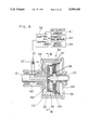
- FIG. 13 is a cross-sectional view of still another torque transmission device constituting a sixth embodiment of the present invention.
- FIG. 14 is a cross-sectional view of a further torque transmission device constituting a seventh embodiment
- FIG. 15 is a cross-sectional view of an eighth embodiment according to the present invention.
- FIG. 16 is a fragmentary sectional view taken along the line XVI--XVI in FIG. 15;
- FIG. 17 is a longitudinal sectional view of a ninth embodiment of the present invention.
- FIG. 18 is an enlarged fragmentary view of a portion shown in FIG. 17;
- FIG. 19 is a graph showing a transmissive torque characteristic of the tenth embodiment
- FIG. 20 is a longitudinal sectional view of a tenth embodiment of the present invention.
- FIG. 21 is a longitudinal sectional view of an eleventh embodiment of the present invention.
- FIG. 22 is a cross-sectional view taken along the line XXII--XXII in FIG. 21;
- FIG. 23 is a longitudinal sectional view of a twelfth embodiment of the present invention.
- FIG. 24 is a longitudinal sectional view of a thirteenth embodiment of the present invention.
- FIG. 25 is a longitudinal sectional view of a fourteenth embodiment of the present invention.
- FIG. 1 there is schematically shown a drive system of a four-wheel drive vehicle comprising an engine 10, which transmits the rotational power to a front drive shaft 12 through a transmission 11.
- the rotation of the shaft 12 is in turn transmitted to left and right front wheels 15, 16 through a front axle including a front differential unit 13.
- the front drive shaft 12 is drivingly connected to a rear drive shaft 20 through a torque transmission device 30 according to the present invention which is constructed as referred to later.
- the rotational torque transmitted to the rear drive shaft 20 is further transmitted to left and right rear wheels 23, 24 through a rear axle including a rear differential unit 21.
- Various embodiments of the torque transmission device 30 will be described hereinafter.
- reference numeral 31 denotes a front end cap 31 connected to one end of the front drive shaft 12.
- a cylindrical rotary housing 32 provided coaxially with the front drive shaft 12 is secured to the front end cap 31 at one end and to a rear end cap 33 at the other end.
- the front end cap 31, the rotary housing 32 and the rear end cap 33 compose a rotary housing assembly.
- the end caps 31, 33 rotatably carries one end portion of the rear drive shaft 20 through a pair of bearings (not numbered) in coaxial relation with the front drive shaft 12.
- a plurality of outer clutch discs 37 are spline-engaged with an internal surface of the rotary housing 32, while a plurality of inner clutch discs 38 are spline-engaged with an external surface portion of the rear drive shaft 20.
- the outer and inner clutch discs 37, 38 are arranged in alternate fashion, thereby constituting a multiple disc clutch 40.
- the rotary housing 32 slidably receives a clutch operating piston 36 between the front end cap 31 and the multiple disc clutch 40.
- the pressure acting on the piston 36 moves the same to press the clutch discs 37, 38.
- a drive torque applied to the rotary housing 32 from the front drive shaft 12 is transmitted to the rear drive shaft 20 through the clutch discs 37, 38.
- the torque so transmitted to the rear drive shaft 20 varies depending on the pressure acting on the piston 36.
- a circular rotor chamber 42 within which a thin impeller or rotor 41 of approximately the same axial width (e.g., 2 or 3 millimeters) as that of the chamber 42 is received with opposite end surfaces thereof being slidable on the facing end surfaces of the front end cap 31 and the piston 36.
- the rotor 41 is spline-connected at its central portion with the external surface of the rear drive shaft 20 and is provided with a plurality (four in this embodiment) of blade portions 41a-41d which radially extend at regular intervals in circumferential direction.
- the rotor 41 has an axial clearance of 0.1-0.65 mm (millimeter) at either side relative to the front end cap 31 and the piston 36 and a radial clearance of 0.05-0.025 mm at each of the external end surface relative to the internal surface of the rotary housing 32.
- the axial clearance between any adjacent two of the clutch discs 37, 38 is set in the range of 0-0.1 millimeter, and those at the axial opposite axial sides of the clutch discs 37, 38 are maintained in friction contact with the piston 36 and the rear end cap 33.
- the piston 36 is axially moved 0.1 millimeter to press the clutch discs 37, 38 when torque of a magnitude, e.g., 20 kg-cm (kilogrammeters) is transmitted between the front and rear drive shafts 12, 20.
- torque of a magnitude e.g. 20 kg-cm (kilogrammeters) is transmitted between the front and rear drive shafts 12, 20.
- FIGS. 4 to 7 show second and third embodiments of the present invention, wherein the torque transmission device as described above is improved in that means is provided for tuning up the torque transmission characteristic.
- a throttle hole or orifice 53 is formed in each of two blade portions 41a, 41b of the rotor 41 so that a pressure is relieved from the high pressure area B right before each of the blade portions 41a-41b to the low pressure area A right behind the same blade portion.
- the diameter of the orifice 53 the pressure generated within each of two space sections 43 is adjusted, so that the force of the piston 36 pressing the clutch discs 37, 38 and hence the transmissive torque can be tuned up by varying the diameter of the orifices 53, as shown in FIG. 7.
- annular groove 50 is formed at one end surface of the piston 36 which faces the rotor 41, and an annular plate 51 is tightly fitted in the annular groove 50 to constitute an annular channel (not numbered) in the piston 36.
- a plurality (preferably, four) of orifices 53 are formed in the annular plate 51 at a regular circumferential interval each for communication with the rotor chamber 42 and the annular channel in the piston 36.
- FIGS. 8 to 10 show a fourth embodiment of the present invention, in which the transmissive torque can be controlled depending upon the driving conditions of the vehicle.
- the front end cap which is illustrated as one body with the front drive shaft 12 and the rotary housing 32 is formed with a plurality (preferably, two pairs) of bypass passages 55, 56 which open to the rotor chamber 42 at a regular circumferential interval.
- the first pair of diametrically mating bypass passages 55, 55 are always in communication with each other, and the second pair of diametrically mating holes 56, 56 are also always in communication with each other.
- an electromagnetic throttle valve 57 In order to permit selective communication between the bypass passages 55 and 56, there is provided an electromagnetic throttle valve 57.
- This valve 57 varies the degree of its throttle opening depending upon the magnitude of an electric current (I) applied from an electronic controller 58.
- the controller 58 determines the magnitude of the electric current (I) based on various information applied thereto from, for example, a vehicle speed sensor 59, a steering angle sensor 60 and a road surface sensor 61 which detects the coefficient of friction of the road on which the vehicle travels. Consequently, the opening degree of the throttle valve 57 is varied based on the vehicle traveling conditions. This results in controlling the pressure generated within the rotor chamber 42, whereby the transmissive torque can be varied within the range indicated by the solid and broken curves in FIG. 10.
- numeral 62 denotes a device housing rotatably carrying the front drive shaft 12
- numeral 63 denotes a cap closing an opening end of the device housing 62 and rotatably carrying the rear drive shaft 20.
- the rotor 41 is formed generally as a disc.
- the rotor 41 is formed with a pair of diametrically opposite blade portions 41a, 41b of a uniform thickness, a pair of semi-circular circumferential edge portions 65, 66 having the same thickness as the blade portions 41a, 41b, and four semi-circular or sector cavities 67 which are symmetrically defined by the blade portions 41a, 41b and the edge portions 65, 66 at axial opposite ends of the rotor 41.
- reference numeral 68 denotes a rear shaft sleeve which is connectable with the rear drive shaft 20 through spline engagement, as shown, for example, in FIG. 17.
- the sixth to eights embodiments use the rotor 41 having a pair of diametrically opposite blade portions 41a, 41b as used in the aforementioned second embodiment.
- the rotor 41 is provided with a pair of round communication holes 70, 70 which extend across the blade portions 41a, 41b to open to the opposite sides thereof.
- a pair of elongate communication holes 71, 71 are formed in the blade portions 41a, 41b of the rotor 41 in place of the round holes 70, 70 as used in the sixth embodiment.
- the pressures at the axial opposite sides of the blade portions 41a, 41b are balanced by virtue of the communication holes 70, 70 or 71, 71.
- the flexing of the blade portions 41a, 41b due to the pressure unbalance at the axial opposite sides thereof can be obviated, thereby avoiding local abrasion of the blade portions 41a, 41b and the side surfaces of the front end cap 31 (or rotary housing 32) and the piston 36 which may otherwise be caused by the deviation of the blade portions 41a, 41b.
- the eighth embodiment shown in FIGS. 15 and 16 uses the rotor 41 wherein each of the blade portions 41a, 41b is sharpened as knife edge at front and rear edges in the rotational direction.
- a pair of wedge shape spaces are defined by the slanted surfaces of each knife edge portion 72 and the end surfaces of the front end cap 31 (or rotary housing 32) and the piston 36.
- the wedge shape spaces positively admit the high viscous oil therein, so that the high viscous oil so admitted generates a righting force to position the blade portions 41a, 41b to the axial mid position within the rotor chamber 42.
- FIGS. 17 through 19 Another improvement of the present invention is illustrated as a ninth embodiment in FIGS. 17 through 19.
- This particular improvement includes a mechanism which is designed to augment the pressing force acting on the clutch discs 37, 38 when the rotational speed difference between front and rear drive shafts 12, 20 exceeds a predetermined speed so that excessive abrasion of the clutch discs 37, 38 can be obviated.
- the mechanism comprises an inner clutch hub 75 rotatably carried over the rear shaft sleeve 68.
- the hub 75 is spline-engaged at its external surface with the inner clutch discs 38 and is formed with a pressing flange portion 75a interposed between the piston 36 and the clutch discs 37, 38.
- a flanged transmission sleeve 76 which is spline-engaged over the shaft sleeve 68 is formed with a circular array of radial extending teeth 76a at a flange portion thereof, as shown more detail in FIG. 18.
- another circular array of radial extending teeth 75a are formed on the clutch hub 75 for engagement with those on the transmission sleeve 76.
- a spring 77 is provided to bring the teeth 75a on the hub 75 into engagement with those on the sleeve 76.
- each of the teeth 76a on the sleeve 76 causes the mating one of the teeth 75a on the hub 75 to slightly slide thereon by the wedge action therebetween, as indicated by the phantom line in FIG. 18.
- the hub 75 is axially moved against the spring 76 to apply an augmentative force to the clutch discs 37, 38 in addition to that applied by the piston 36. Consequently, the frictional sliding movements between the clutch discs 37, 38 can be prevented.
- the rotor chamber 42 which rotatably receives the rotor 41 having the pair of diametrically opposite blade portions 41a, 41b is defined as a side groove formed at one side of the piston 36, so that an annular circumferential edge portion at one side of the piston 36 is seated on the bottom surface of a cylindrical bore of the rotary housing 32.
- the half 38B of the inner clutch discs 38 are spline-engaged with the shaft sleeve 68 into which one end of the rear drive shaft 20 is inserted for spline engagement, while the remaining half 38A of the inner clutch discs 38 are spline-engaged with an inner disc hub 80 which is rotatably carried over the shaft sleeve 68.
- the hub 80 is formed with a flange portion 80a, which cooperates with the piston 36 to press the clutch discs 37, 38 thereupon.
- a flanged sleeve 81 which is restricted by a thrust bearing 82 to retract away from the hub 80 is carried over the shaft sleeve 68 and is spline-engaged therewith.
- a cross V-slot 83 is formed at a flange portion of the sleeve 81, while four retaining holes (not numbered) are formed at one side surface of the hub 80 which faces the flange portion of the flanged sleeve 81.
- the V-slot 83 and retaining holes cooperate to retain four steel balls 84 respectively in the retaining holes.
- Washer springs 85 are interposed between the hub 80 and the flanged sleeve 81 so as to urge the latter toward the former so that each of the balls 84 is normally seated at the center of each segment of the V-slot 83.
- the front drive shaft 12 rotates relative to the rear drive shaft 20 at more than the predetermined speed as indicated at (A) in FIG.
- each of the balls 84 rolls on a slanted surface of the mating V-slot segment, and the hub 80 is axially moved to augment the engagement between the clutch discs 37, 38.
- slippage between the clutch discs 37, 38 is prevented, whereby the transmissive torque is increased at the larger rate as shown in FIG. 19 as the rotational speed difference ( ⁇ N) between the drive shafts 12, 20 increases beyond the predetermined speed difference (A).
- an eleventh embodiment of the present invention is improved in that any independent pin member is not used in connecting the piston 36 with the rotary housing 32 for integral rotation. More specifically, as shown in FIGS. 21 and 22, the piston 36 is formed with a spline portion 88 at its circumferential edge portion close to the clutch discs 37, 38, and the spline portion 88 is engaged with a mating spline portion 89 which is formed at the internal surface of the rotary housing 32 to engage with the outer clutch discs 37.
- the failure to assemble any such pin member into the device can be obviated because no such pin member is employed.
- the rotary housing 32 and the child piston 92 snugly fit over the shaft sleeve 68 so that a clutch disc chamber 96 is defined by the shaft sleeve 68, rotary housing 32, piston 36 and child piston 92.
- a lubricant for the clutch discs 37, 38 is filled within the chamber 96.
- the child piston 92 is axially moved against the springs 93, 94 when the volume of lubricant varies due to thermal changes.
- FIGS. 24 and 25 thirteenth and fourteenth embodiments are exemplified in a simpler form.
- the rotary housing 32 and the rear end cap 33 fitted in the rear opening end of the rotary housing 32 directly carry the rear drive shaft 20.
- the housing 32 and the piston 36 fit over the external surface of the rear drive shaft 20, so that the clutch disc chamber 96 is defined by the housing 32, piston 36 and rear drive shaft 20.
- a generally cylindrical hole 100 is coaxially formed within the rear drive shaft 20.
- an absorption piston 101 is slidably fitted in the cylindrical hole 100 and is biassed by means of a spring 102 which is seated on a nut 103 screwed in an opening end of the cylindrical hole 100.
- a stepped small hole 104 formed at the bottom of the hole 100 communicates with the clutch disc chamber 96 through a radial passage 105.
- a diaphragm 107 is secured to close the opening end of the cylindrical hole 100.
- the absorption mechanism including the piston 101 or the diaphragm 107 may be provided not within the rear drive shaft 20, but within the rotary housing 32.
- the rotor 41 is driven by the rear drive shaft 20 or the shaft sleeve 68 into which the shaft 20 is fitted in any of the aforementioned embodiments, it may be modified to be driven bodily with the rotary housing 32 in which modified instance, the piston 36 and the front end cap 31 interposing the rotor 41 therebetween may be rotated bodily with the shaft 20 or the shaft sleeve 68.
- any of the aforementioned torque transmission device may be applied to automobiles of the type wherein the rotational torque generated by the engine 10 is transmitted first to the rear drive shaft 20 for the rear wheels 23, 24 and then, to the front drive shaft 12 for the front wheels 15, 16.
Abstract
Description
Claims (3)
Applications Claiming Priority (6)
| Application Number | Priority Date | Filing Date | Title |
|---|---|---|---|
| JP62251305A JPH0193631A (en) | 1987-10-05 | 1987-10-05 | Driving force transmitting device |
| JP62-251305 | 1987-10-05 | ||
| JP62297391A JP2518321B2 (en) | 1987-11-27 | 1987-11-27 | Driving force transmission device |
| JP62-297391 | 1987-11-27 | ||
| JP62-198046[U] | 1987-12-26 | ||
| JP19804687U JPH0736187Y2 (en) | 1987-12-26 | 1987-12-26 | Driving force transmission device |
Related Parent Applications (1)
| Application Number | Title | Priority Date | Filing Date |
|---|---|---|---|
| US07/165,072 Division US4905808A (en) | 1987-03-27 | 1988-03-07 | Torque transmission device for a four-wheel drive vehicle |
Publications (1)
| Publication Number | Publication Date |
|---|---|
| US5056640A true US5056640A (en) | 1991-10-15 |
Family
ID=27327457
Family Applications (1)
| Application Number | Title | Priority Date | Filing Date |
|---|---|---|---|
| US07/439,429 Expired - Lifetime US5056640A (en) | 1987-10-05 | 1989-11-21 | Torque transmission device for a four-wheel drive vehicle |
Country Status (1)
| Country | Link |
|---|---|
| US (1) | US5056640A (en) |
Cited By (24)
| Publication number | Priority date | Publication date | Assignee | Title |
|---|---|---|---|---|
| US5174408A (en) * | 1989-10-20 | 1992-12-29 | Viscodrive Gmbh | Drive assembly for a four wheel drive vehicle, having a disconnectable viscous coupling |
| US5219038A (en) * | 1989-11-15 | 1993-06-15 | Honda Giken Kogyo Kabushiki Kaisha | Power transmission device for a four-wheel drive vehicle |
| DE4327519A1 (en) * | 1993-08-17 | 1995-02-23 | Gkn Viscodrive Gmbh | Method and device for controlling a clutch |
| DE4424255A1 (en) * | 1993-08-17 | 1996-01-11 | Gkn Viscodrive Gmbh | Torque transmitting clutch between two relatively rotary parts |
| US5556350A (en) * | 1993-08-31 | 1996-09-17 | Gkn Viscodrive Gmbh | Differential drive |
| US5556343A (en) * | 1993-12-17 | 1996-09-17 | Gkn Automotive Ag | Method and device for controlling a coupling |
| US5616096A (en) * | 1994-08-18 | 1997-04-01 | Viscodrive Japan Ltd. | Differential gear unit |
| US5632185A (en) * | 1994-12-10 | 1997-05-27 | Gkn Viscodrive Gmbh | Axle drive for distributing torque |
| US5634507A (en) * | 1994-10-11 | 1997-06-03 | Gkn Viscodrive Gmbh | Driving device for vertically movable shutters |
| US5637050A (en) * | 1995-02-22 | 1997-06-10 | Gkn Viscodrive Gmbh | Differential drive with locking effect |
| US5658214A (en) * | 1995-02-10 | 1997-08-19 | Gkn Viscodrive Gmbh | Differential drive |
| US5662196A (en) * | 1994-06-01 | 1997-09-02 | Gkn Viscodrive Gmbh | Viscous coupling having a toothed hub used as carrier for the inner plates |
| US5690201A (en) * | 1995-02-21 | 1997-11-25 | Gkn Viscodrive Gmbh | Method and device for controlling a coupling |
| US5713811A (en) * | 1995-07-21 | 1998-02-03 | Gkn Birfield Ag | Differential drive with differential gears having spherical bearing journals |
| GB2315531A (en) * | 1996-07-17 | 1998-02-04 | Toyoda Machine Works Ltd | Viscous and electromagnetic actuation of a friction coupling |
| US5862875A (en) * | 1995-05-31 | 1999-01-26 | Hyundai Motor Company | Differential control unit for front and rear wheels of a 4-wheel drive vehicle |
| US5890573A (en) * | 1995-12-21 | 1999-04-06 | Gkn Viscodrive Gmbh | Coupling unit having at least one viscous coupling and one friction coupling |
| US6123134A (en) * | 1999-04-07 | 2000-09-26 | Clopay Building Products Company, Inc. | Method and apparatus for regulating the closing speed of a rolling fire door |
| US6193006B1 (en) * | 1999-08-30 | 2001-02-27 | General Motors Corporation | Dynamic all wheel drive control |
| US6474433B1 (en) * | 1999-12-10 | 2002-11-05 | Spicer Technology Inc. | Speed sensitive on-demand torque coupling differential |
| US6547025B1 (en) * | 1999-03-18 | 2003-04-15 | Gkn Automotive, Inc. | All wheel drive system for a motor vehicle |
| WO2004070224A1 (en) * | 2003-02-03 | 2004-08-19 | Gkn Driveline International Gmbh | Actuator, particularly for a friction clutch with displacement by magnetorheological fluid |
| US20100248888A1 (en) * | 2006-08-17 | 2010-09-30 | Daimler Ag | Tandem axle having two drivable axles and a drivetrain which can be partially disconnected |
| US20150098841A1 (en) * | 2013-10-09 | 2015-04-09 | Chart Inc. | Spin Pump With Spun-Epicyclic Geometry |
Citations (24)
| Publication number | Priority date | Publication date | Assignee | Title |
|---|---|---|---|---|
| US3490312A (en) * | 1968-05-31 | 1970-01-20 | Gen Motors Corp | Expansible chamber device with hydrodynamic bearing pump and limited slip differential employing same |
| US3534633A (en) * | 1968-09-09 | 1970-10-20 | Rockwell Standard Co | Differential with output torque distribution control |
| US3628399A (en) * | 1970-07-22 | 1971-12-21 | Gen Motors Corp | Hydraulic limited slip differential |
| US4013154A (en) * | 1975-11-06 | 1977-03-22 | Eaton Corporation | Mounting nut retention for fluid couplings |
| US4012968A (en) * | 1974-12-23 | 1977-03-22 | Borg-Warner Corporation | Speed-sensitive differential mechanism |
| US4031780A (en) * | 1974-11-29 | 1977-06-28 | Chrysler Corporation | Coupling apparatus for full time four wheel drive |
| US4040271A (en) * | 1975-10-22 | 1977-08-09 | Harry Ferguson Limited | Viscous shear couplings |
| US4048872A (en) * | 1974-05-28 | 1977-09-20 | Gkn Transmissions Limited | Control couplings |
| US4058027A (en) * | 1976-07-09 | 1977-11-15 | Gkn Transmissions Limited | Control couplings |
| US4369671A (en) * | 1979-12-12 | 1983-01-25 | Aisin Warner Kabushiki Kaisha | Torque transfer mechanism with hydraulic control system for a four wheel drive vehicle |
| US4444298A (en) * | 1981-07-10 | 1984-04-24 | The Secretary Of State For Defence In Her Britannic Majesty's Government Of The United Kingdom Of Great Britain And Northern Ireland | Viscous shear clutch |
| JPS60252026A (en) * | 1984-05-29 | 1985-12-12 | Mitsubishi Motors Corp | Transfer clutch apparatus for 4-wheel driving car |
| GB2163107A (en) * | 1984-08-15 | 1986-02-19 | Fuji Heavy Ind Ltd | Four-wheel drive vehicle transmission |
| GB2171967A (en) * | 1985-03-06 | 1986-09-10 | Dana Corp | Vehicle gear assembly for torque transfer to two or four-wheels |
| EP0202951A2 (en) * | 1985-05-24 | 1986-11-26 | Toyota Jidosha Kabushiki Kaisha | Power transfer device for four-wheel drive |
| US4662499A (en) * | 1984-07-18 | 1987-05-05 | Uni-Cardan Aktiengesellschaft | Control clutch with interacting viscous control unit and frictional clutch unit |
| US4667534A (en) * | 1985-10-18 | 1987-05-26 | Tochigi-Fuji Sangyo Kabushiki Kaisha | Limited slip differential gear mechanism |
| DE3545540A1 (en) * | 1985-12-21 | 1987-07-02 | Audi Ag | Drive device for a four-wheel drive motor vehicle |
| DE3706075A1 (en) * | 1986-02-26 | 1987-08-27 | Fuji Heavy Ind Ltd | POWER TRANSMISSION SYSTEM FOR A VEHICLE WITH FOUR-WHEEL DRIVE |
| EP0236650A1 (en) * | 1986-01-24 | 1987-09-16 | Automobiles Peugeot | Driving device for two aligned shafts, with a differential, especially for two rear axle transmission shafts of a vehicle |
| US4719998A (en) * | 1984-05-29 | 1988-01-19 | Mitsubishi Jidosha Kogyo Kabushiki Kaisha | Power transmission system for vehicle |
| US4821604A (en) * | 1986-06-06 | 1989-04-18 | Toyoda Koki Kabushiki Kaisha | Four-wheel drive system |
| US4905808A (en) * | 1987-03-27 | 1990-03-06 | Toyoda Koki Kabushiki Kaisha | Torque transmission device for a four-wheel drive vehicle |
| US4909371A (en) * | 1987-07-23 | 1990-03-20 | Daihatsu Motor Co., Ltd. | Four wheel driving power |
-
1989
- 1989-11-21 US US07/439,429 patent/US5056640A/en not_active Expired - Lifetime
Patent Citations (24)
| Publication number | Priority date | Publication date | Assignee | Title |
|---|---|---|---|---|
| US3490312A (en) * | 1968-05-31 | 1970-01-20 | Gen Motors Corp | Expansible chamber device with hydrodynamic bearing pump and limited slip differential employing same |
| US3534633A (en) * | 1968-09-09 | 1970-10-20 | Rockwell Standard Co | Differential with output torque distribution control |
| US3628399A (en) * | 1970-07-22 | 1971-12-21 | Gen Motors Corp | Hydraulic limited slip differential |
| US4048872A (en) * | 1974-05-28 | 1977-09-20 | Gkn Transmissions Limited | Control couplings |
| US4031780A (en) * | 1974-11-29 | 1977-06-28 | Chrysler Corporation | Coupling apparatus for full time four wheel drive |
| US4012968A (en) * | 1974-12-23 | 1977-03-22 | Borg-Warner Corporation | Speed-sensitive differential mechanism |
| US4040271A (en) * | 1975-10-22 | 1977-08-09 | Harry Ferguson Limited | Viscous shear couplings |
| US4013154A (en) * | 1975-11-06 | 1977-03-22 | Eaton Corporation | Mounting nut retention for fluid couplings |
| US4058027A (en) * | 1976-07-09 | 1977-11-15 | Gkn Transmissions Limited | Control couplings |
| US4369671A (en) * | 1979-12-12 | 1983-01-25 | Aisin Warner Kabushiki Kaisha | Torque transfer mechanism with hydraulic control system for a four wheel drive vehicle |
| US4444298A (en) * | 1981-07-10 | 1984-04-24 | The Secretary Of State For Defence In Her Britannic Majesty's Government Of The United Kingdom Of Great Britain And Northern Ireland | Viscous shear clutch |
| JPS60252026A (en) * | 1984-05-29 | 1985-12-12 | Mitsubishi Motors Corp | Transfer clutch apparatus for 4-wheel driving car |
| US4719998A (en) * | 1984-05-29 | 1988-01-19 | Mitsubishi Jidosha Kogyo Kabushiki Kaisha | Power transmission system for vehicle |
| US4662499A (en) * | 1984-07-18 | 1987-05-05 | Uni-Cardan Aktiengesellschaft | Control clutch with interacting viscous control unit and frictional clutch unit |
| GB2163107A (en) * | 1984-08-15 | 1986-02-19 | Fuji Heavy Ind Ltd | Four-wheel drive vehicle transmission |
| GB2171967A (en) * | 1985-03-06 | 1986-09-10 | Dana Corp | Vehicle gear assembly for torque transfer to two or four-wheels |
| EP0202951A2 (en) * | 1985-05-24 | 1986-11-26 | Toyota Jidosha Kabushiki Kaisha | Power transfer device for four-wheel drive |
| US4667534A (en) * | 1985-10-18 | 1987-05-26 | Tochigi-Fuji Sangyo Kabushiki Kaisha | Limited slip differential gear mechanism |
| DE3545540A1 (en) * | 1985-12-21 | 1987-07-02 | Audi Ag | Drive device for a four-wheel drive motor vehicle |
| EP0236650A1 (en) * | 1986-01-24 | 1987-09-16 | Automobiles Peugeot | Driving device for two aligned shafts, with a differential, especially for two rear axle transmission shafts of a vehicle |
| DE3706075A1 (en) * | 1986-02-26 | 1987-08-27 | Fuji Heavy Ind Ltd | POWER TRANSMISSION SYSTEM FOR A VEHICLE WITH FOUR-WHEEL DRIVE |
| US4821604A (en) * | 1986-06-06 | 1989-04-18 | Toyoda Koki Kabushiki Kaisha | Four-wheel drive system |
| US4905808A (en) * | 1987-03-27 | 1990-03-06 | Toyoda Koki Kabushiki Kaisha | Torque transmission device for a four-wheel drive vehicle |
| US4909371A (en) * | 1987-07-23 | 1990-03-20 | Daihatsu Motor Co., Ltd. | Four wheel driving power |
Cited By (40)
| Publication number | Priority date | Publication date | Assignee | Title |
|---|---|---|---|---|
| US5174408A (en) * | 1989-10-20 | 1992-12-29 | Viscodrive Gmbh | Drive assembly for a four wheel drive vehicle, having a disconnectable viscous coupling |
| US5314039A (en) * | 1989-10-20 | 1994-05-24 | Viscodrive Gmbh | Drive assembly for a four wheel drive vehicle, having a disconnectable viscous coupling |
| US5219038A (en) * | 1989-11-15 | 1993-06-15 | Honda Giken Kogyo Kabushiki Kaisha | Power transmission device for a four-wheel drive vehicle |
| US5706923A (en) * | 1993-08-17 | 1998-01-13 | Gkn Automotive Ag | Method of and device for controlling a coupling |
| US5526912A (en) * | 1993-08-17 | 1996-06-18 | Gkn Automotive Ag | Method of and device for controlling a coupling |
| DE4424255C2 (en) * | 1993-08-17 | 2001-10-18 | Gkn Viscodrive Gmbh | Device for controlling a clutch |
| DE4327519A1 (en) * | 1993-08-17 | 1995-02-23 | Gkn Viscodrive Gmbh | Method and device for controlling a clutch |
| DE4327519C2 (en) * | 1993-08-17 | 2000-12-14 | Gkn Viscodrive Gmbh | Device for controlling a clutch |
| DE4345484C2 (en) * | 1993-08-17 | 2001-01-11 | Gkn Viscodrive Gmbh | Device for controlling a viscous coupling |
| DE4424255A1 (en) * | 1993-08-17 | 1996-01-11 | Gkn Viscodrive Gmbh | Torque transmitting clutch between two relatively rotary parts |
| US5556350A (en) * | 1993-08-31 | 1996-09-17 | Gkn Viscodrive Gmbh | Differential drive |
| US5935036A (en) * | 1993-12-17 | 1999-08-10 | Gkn Automotive Ag | Method and device for controlling a coupling |
| US5556343A (en) * | 1993-12-17 | 1996-09-17 | Gkn Automotive Ag | Method and device for controlling a coupling |
| US5662196A (en) * | 1994-06-01 | 1997-09-02 | Gkn Viscodrive Gmbh | Viscous coupling having a toothed hub used as carrier for the inner plates |
| US5791446A (en) * | 1994-06-01 | 1998-08-11 | Gkn Viscodrive Gmbh | Viscous coupling having a toothed hub used as a carrier for the inner |
| US5616096A (en) * | 1994-08-18 | 1997-04-01 | Viscodrive Japan Ltd. | Differential gear unit |
| US5634507A (en) * | 1994-10-11 | 1997-06-03 | Gkn Viscodrive Gmbh | Driving device for vertically movable shutters |
| US5632185A (en) * | 1994-12-10 | 1997-05-27 | Gkn Viscodrive Gmbh | Axle drive for distributing torque |
| US5658214A (en) * | 1995-02-10 | 1997-08-19 | Gkn Viscodrive Gmbh | Differential drive |
| US5690201A (en) * | 1995-02-21 | 1997-11-25 | Gkn Viscodrive Gmbh | Method and device for controlling a coupling |
| US5637050A (en) * | 1995-02-22 | 1997-06-10 | Gkn Viscodrive Gmbh | Differential drive with locking effect |
| US5862875A (en) * | 1995-05-31 | 1999-01-26 | Hyundai Motor Company | Differential control unit for front and rear wheels of a 4-wheel drive vehicle |
| US5713811A (en) * | 1995-07-21 | 1998-02-03 | Gkn Birfield Ag | Differential drive with differential gears having spherical bearing journals |
| US5890573A (en) * | 1995-12-21 | 1999-04-06 | Gkn Viscodrive Gmbh | Coupling unit having at least one viscous coupling and one friction coupling |
| US5954173A (en) * | 1996-07-17 | 1999-09-21 | Toyoda Koki Kabushiki Kaisha | Drive force transmission apparatus |
| GB2315531B (en) * | 1996-07-17 | 2001-01-17 | Toyoda Machine Works Ltd | Drive force transmission apparatus |
| GB2315531A (en) * | 1996-07-17 | 1998-02-04 | Toyoda Machine Works Ltd | Viscous and electromagnetic actuation of a friction coupling |
| US6547025B1 (en) * | 1999-03-18 | 2003-04-15 | Gkn Automotive, Inc. | All wheel drive system for a motor vehicle |
| US6123134A (en) * | 1999-04-07 | 2000-09-26 | Clopay Building Products Company, Inc. | Method and apparatus for regulating the closing speed of a rolling fire door |
| US6193006B1 (en) * | 1999-08-30 | 2001-02-27 | General Motors Corporation | Dynamic all wheel drive control |
| US6474433B1 (en) * | 1999-12-10 | 2002-11-05 | Spicer Technology Inc. | Speed sensitive on-demand torque coupling differential |
| DE10304140B3 (en) * | 2003-02-03 | 2004-10-21 | Gkn Driveline International Gmbh | Friction clutch with adjustment by magneto-rheological fluid |
| WO2004070224A1 (en) * | 2003-02-03 | 2004-08-19 | Gkn Driveline International Gmbh | Actuator, particularly for a friction clutch with displacement by magnetorheological fluid |
| US20060272915A1 (en) * | 2003-02-03 | 2006-12-07 | Gkn Driveline International Gmbh | Actuator, particularly for a friction clutch with dispalcement by magnetorheological fluid |
| US20100248888A1 (en) * | 2006-08-17 | 2010-09-30 | Daimler Ag | Tandem axle having two drivable axles and a drivetrain which can be partially disconnected |
| US8562479B2 (en) * | 2006-08-17 | 2013-10-22 | Daimler Ag | Tandem axle having two drivable axles and a drivetrain which can be partially disconnected |
| US20150098841A1 (en) * | 2013-10-09 | 2015-04-09 | Chart Inc. | Spin Pump With Spun-Epicyclic Geometry |
| US9771931B2 (en) * | 2013-10-09 | 2017-09-26 | Chart Inc. | Spin pump with spun-epicyclic geometry |
| US20180073493A1 (en) * | 2013-10-09 | 2018-03-15 | Chart Inc. | Spin pump with spun-epicyclic geometry |
| US10465669B2 (en) * | 2013-10-09 | 2019-11-05 | Chart Inc. | Spin pump with spun-epicyclic geometry having piston bores capped with caps including ducts or valves within the rotor |
Similar Documents
| Publication | Publication Date | Title |
|---|---|---|
| US4905808A (en) | Torque transmission device for a four-wheel drive vehicle | |
| US5056640A (en) | Torque transmission device for a four-wheel drive vehicle | |
| EP0391722B1 (en) | Viscous clutch assembly for torque transmission in motor vehicle | |
| US4960011A (en) | Differential drive mechanism | |
| US5197583A (en) | Torque transmission device | |
| US5012908A (en) | Control coupling for torque transmission | |
| EP0283821B1 (en) | Torque transmission device for a four-wheel drive vehicle | |
| JPH10281267A (en) | Differential gear for automobile driving line | |
| US5215506A (en) | Electronically controlled differential limiting system | |
| US5063738A (en) | Pressure generation and responsive mechanism with high viscous fluid | |
| US6216841B1 (en) | Hydraulic clutch | |
| JPS62286838A (en) | Torque transmission device | |
| JPH01126440A (en) | Driving force transmitting apparatus | |
| US5133438A (en) | Viscous coupling with spacer rings | |
| US5967275A (en) | Transmitting coupling with maneuvering characteristics | |
| JPH0266327A (en) | Fluid frictional clutch | |
| JP2611563B2 (en) | Front and rear wheel drive devices for automobiles | |
| KR950008991B1 (en) | Differential gear | |
| JP2522810B2 (en) | Driving force transmission device | |
| JPH0629543Y2 (en) | Drive coupling device for four-wheel drive | |
| JPS6388328A (en) | Torque transmitter | |
| JPH0349307Y2 (en) | ||
| JPH0293124A (en) | Controlled rotation-difference sensing type joint | |
| SU1172760A1 (en) | End transmission of vehicle | |
| JP2530706Y2 (en) | Power transmission device |
Legal Events
| Date | Code | Title | Description |
|---|---|---|---|
| STCF | Information on status: patent grant |
Free format text: PATENTED CASE |
|
| AS | Assignment |
Owner name: TOYOTA MOTOR CORPORATION Free format text: ASSIGNMENT OF ASSIGNORS INTEREST.;ASSIGNOR:TOYODA KOKI KABUSHIKI KAISHA;REEL/FRAME:005828/0826 Effective date: 19910827 Owner name: TOYODA KOKI KABUSHIKI KAISHA Free format text: ASSIGNMENT OF ASSIGNORS INTEREST.;ASSIGNOR:TOYODA KOKI KABUSHIKI KAISHA;REEL/FRAME:005828/0826 Effective date: 19910827 |
|
| FEPP | Fee payment procedure |
Free format text: PAYOR NUMBER ASSIGNED (ORIGINAL EVENT CODE: ASPN); ENTITY STATUS OF PATENT OWNER: LARGE ENTITY |
|
| FPAY | Fee payment |
Year of fee payment: 4 |
|
| FPAY | Fee payment |
Year of fee payment: 8 |
|
| FPAY | Fee payment |
Year of fee payment: 12 |