US511367A - slater - Google Patents
slater Download PDFInfo
- Publication number
- US511367A US511367A US511367DA US511367A US 511367 A US511367 A US 511367A US 511367D A US511367D A US 511367DA US 511367 A US511367 A US 511367A
- Authority
- US
- United States
- Prior art keywords
- standards
- stand
- machine
- scotches
- cycle
- Prior art date
- Legal status (The legal status is an assumption and is not a legal conclusion. Google has not performed a legal analysis and makes no representation as to the accuracy of the status listed.)
- Expired - Lifetime
Links
- 241000053208 Porcellio laevis Species 0.000 title description 4
- 210000002683 Foot Anatomy 0.000 description 18
- 238000010276 construction Methods 0.000 description 6
- 241000908127 Porcellio scaber Species 0.000 description 4
- 230000000694 effects Effects 0.000 description 4
- XEEYBQQBJWHFJM-UHFFFAOYSA-N iron Chemical compound [Fe] XEEYBQQBJWHFJM-UHFFFAOYSA-N 0.000 description 4
- 230000000414 obstructive Effects 0.000 description 4
- 239000007858 starting material Substances 0.000 description 4
- 210000000474 Heel Anatomy 0.000 description 2
- 210000002370 ICC Anatomy 0.000 description 2
- 229910001296 Malleable iron Inorganic materials 0.000 description 2
- 210000003371 Toes Anatomy 0.000 description 2
- 230000000903 blocking Effects 0.000 description 2
- 238000007373 indentation Methods 0.000 description 2
- 229910052742 iron Inorganic materials 0.000 description 2
- 239000010985 leather Substances 0.000 description 2
- 239000000463 material Substances 0.000 description 2
- 239000002184 metal Substances 0.000 description 2
- 229910052751 metal Inorganic materials 0.000 description 2
- 230000036633 rest Effects 0.000 description 2
- 230000000284 resting Effects 0.000 description 2
- 230000000717 retained Effects 0.000 description 2
Images


Classifications
-
- B—PERFORMING OPERATIONS; TRANSPORTING
- B62—LAND VEHICLES FOR TRAVELLING OTHERWISE THAN ON RAILS
- B62H—CYCLE STANDS; SUPPORTS OR HOLDERS FOR PARKING OR STORING CYCLES; APPLIANCES PREVENTING OR INDICATING UNAUTHORIZED USE OR THEFT OF CYCLES; LOCKS INTEGRAL WITH CYCLES; DEVICES FOR LEARNING TO RIDE CYCLES
- B62H3/00—Separate supports or holders for parking or storing cycles
Definitions
- This invention relates to the construction of an improved stand for bicycles and similar velocipedes theobject of the invention being to support the bicycle in a vertical position.
- the frame is so constructed that the cycle or machine is supported from falling sidewise by the handles with the hind wheel scotched by an attachment connected with the frame which supports the front part of the cycle, so that there is no undue strain upon the machine which can be placed upon the stand without any great efiort, and without directly lifting the machine on to the same.
- the stand When not in use the stand can be easily folded up and put out of the way.
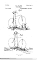
- FIG. 1 is a perspective view of one form of the stand ready for use.
- Fig. 2 is a side elevation showing it in the position adapted for placing the machine in it, the machine being represented in dotted lines.
- Fig. 3 is a side elevation showing it with the machine,
- Fig. 4 is a detail of one of the scotches.
- Figs. 5 and 6 are elevations of an alternative form of the stand shown in Figs. 1 to 3, these figures showing the stand respectively in and out of use.
- Fig. 7 is a perspective view of a stand constructed for use as a home trainer.
- Fig. 8 is a perspective view of a modified form of home-trainer.
- Figs. 9 and 10 are perspective views of stands constructed for use as race-starters and Fig. 11 is a perspective View of the adjustable scotch thereof.
- Figs. 1 to t A are the standards conveniently made of a single piece of tubing curved at the top and terminating in feet or sockets B adapted to rest upon the ground and provide suflicient support for the frame and machine.
- These feet may be made of any suitable material conveniently malleable cast iron and the standards A may be secured therein by set-screws although it is preferred to merely step them in as then the length can be varied by cutting portions off the standards if required.
- the feet B are extended at B in front of the standards A and are there pierced for the reception of the ends of the Y-shaped piece 0 whose stem 0 is cranked at O partly to.
- the piece G O C may be made of thin iron rod the ends of 0 being screwed and placed through the holes in B and kept in position by nuts upon each side of the bracket.
- the scotches D and E maybe secured upon plates F with enlarged ends F pierced to allow of their sliding upon the rod O and adapted to be fixed thereon by setscrews G.
- standards A may be conveniently in the form of a complete bobbin While the nearer one E may be in the form of a half bobbin, the object being to raise the farther bobbin D higher than the nearer one E and thus prevent the machine from slipping backward; the precise shape of the bobbins may however be varied to suit circumstances.
- each of the standardsA is an adj ustable arm or hook H preferably covered with leather or felt pierced to slide upon the standard and provided with a set-screw H by which it may be fixed at the required height thereon.
- the chain I, Fig. 1 is secured to the link or sleeve J adapted to slide freely upon one of the standards the other end of the chain being when required carried round the other standard so as to form aloop K around the standard the end of the loop being secured to the chain by a padlock L or other convenient means.
- This chain is useful as it may be curled around the neck or head of the bicycle which it thus secures to the standard preventing it from being illicitly removed and also preventing undue side play.
- Figs. 2 and 3 as in the other figures hereinafter described the bicycle is merely indicated diagrammatically.
- the elfect of lowering and raising the supports would be the same if instead of the two hooks H a single central hook or equivalent were employed to grip the machine in some part other than the handle bar as for example under the brake, or at the neck, the result as'to lifting themachine being the same.
- This raising effect as will be seen would be applicable to the front portion of rear-driving tricycles.
- the stand represented in Figs. 5and 6 is of substantially similar construction to that shown in Figs. 1 to 3 the only difference being that whereas the standards A in Figs. 1 to 3 slant backward and the arms or hooks H thereon are normally above the level of the cycle handle-bar the standards in Figs. 5 and 6 slant forward and the arms or hooks H are normally below the level of thecycle handlebar.
- Figs. 7 and 8 are designed to serve both as cycle stands and home-trainers.
- Fig. 7 the standards A are shown supported in shoes B in substantially the same manner as before explained with regard to the foregoing examples but instead of inclining backward or forward they may be more or less vertical.
- Two T or Y-shaped rods C C are pivoted in the shoes B one at the front and the other at the back of the standards A as shown.
- On the rod 0 are mounted scotches E D which may in all respects be similar to those before described.
- the scotches E D serve for blocking the front wheel of the cycle.
- a bracket Iin which are pivoted two rollers J J the roller J preferably arranged higher than the roller J so that when the cycle isin position on the stand the weight of the hind wheel and the person using the apparatus as a home-trainerwi1l be thrown principally on the roller J thereby reducing the power necessary for operating the cycle.
- the rollers J J may however be arranged at or nearly at the same heightfrom the ground as shown in Fig.8 in which construction no scotches are necessary for the front wheel since there is no tendency on the part of the machine to run forward as there is when the hind wheel is supported on practically one point and that almost immediately below its axis of rotation, as in Fig. 7.
- the brackets I, Figs. 7 and 8 are adjustable on the rods 0 as before mentioned and may be secured in any desired position thereon by the pinching screws G.
- Figs. 9 and 10 are substantially the same as those previously described but can be used for starting purposes in races.
- a board or sheet of metal or other plate M takes the place of the rod 0 O C and upon this the standards A are pivoted substantiallyin the same manner as in Fig. 1 a rod or bar M being screwed or riveted to M to afliord bearings upon which the feet B Fig. 9, in which the standards maybe carried, can rotate.
- scotch D suitable for application to the board or plate M is illustrated.
- the scotch D is secured by screwing or in any convenient manner to the plate N through which passes the screw 0 which also passes through the slot M in the plate M so that the chock can be adjusted upon the plate M and secured by the preferably winged nut O as will be well understood.
- the standards A are shown formed of a single piece of bent tube the junction of the two rims being however at ICC the bottom instead of, as in Fig. 1 at the top.
- the hooks H are placed in the open ends of the standards the handle bar resting upon them as clearly indicated in the figure.
- I may construct the standardsAof fiatiron say one-fourth or threeeighths of an inch in thickness so that when lying on the ground they would project to a very slight extent above its surface and besides this the standards A may be connected to the frame 0 or board or plate M by a disjunctive joint which as soon as the standards fall to the ground automatically releases them from O or M.
- Fig. 10 the board or plate M is shown as terminating at the standards, but it can be carried farther on as in Fig. 9 if desired.
- Two scotches or an indentation in the surface of the board or plate M could be employed to hold the back wheel if desired, but as it is important to start away as quickly as possible in a race it is preferable, where this can be managed, not to have any obstruction in front of the wheel.
- I claim- 1 In a stand for bicycles and the like, one or more standards adapted to be tilted, supporting feet therefor secured to the standards and moving or tilting therewith, a base or frame pivoted to said feet, and adjustable 2.
- the combination of standards A shoes B rod 0 adjustable bracket I rollers J J pinching screw G and supports Hsubstantially as described and illustrated in the accompanying drawings.
Description
a (No Model.) 5 Sheets-Sheet 1. J. S. SLATER.
GYGLBSTAND,
No. 511,367. PatentedDeoiZQ 1893.
ml NAYIONAI. LIYNOGRAFHING COMPANY.
WASHINGTON. n. c.
5 Sheets-Sheet 2.
(No Model.)
' J. S. SLATER.
GYGLE STAND.
.Pat nted Dec.26,1893.
ms NAYIONAL uwoaurmma com lwv. WASHINGTON, n. c.
(No Model.)
. 5 sheets shet 3. J. s. SLATER CYCLE STAND.
No. 511,367. Patented D60. 26, 1893.
1% Model!) 5 SheetsSheet 4. J. s. SLATER.
03501.5 STAND.
Patent-ed Dec. 26, 1893.
me NATIONAL UTNQGRAFNING ccMPANv.
WASNINGTGN, n. o
5 Sheets-Sheet 5.
(No Model.)
J. SLSLATER.
CYCLE STAND.
v0. 511,367. Patented Dec. '26, 1893.
m m J. J
f x g.
"HE NATIONAL LIYHOGRAFHINQ coMPANv.
wAsruNmoN. u. c.
UNITED STATES I PATENT FFIGE.
JOHN SISSON SLATER, OF LYTHAM, ENGLAND.
CYCLE-STAN D.
SPECIFICATION forming part of Letters Patent No. 511,367, dated December 26, 1893.
Application filed November 16,1892. Serial bio-452,183. (No model.)
To all whom it may concern.-
Be it known that I, J OHN Srsson SLATER, a subject of the Queen of England, residing at Seafield, Lytham, England, have invented certain new and useful Improvements in Oycle-Stands Applicable for Use as Home-Trainers and Race-Starters, of which the following is a specification.
This invention relates to the construction of an improved stand for bicycles and similar velocipedes theobject of the invention being to support the bicycle in a vertical position. The frame is so constructed that the cycle or machine is supported from falling sidewise by the handles with the hind wheel scotched by an attachment connected with the frame which supports the front part of the cycle, so that there is no undue strain upon the machine which can be placed upon the stand without any great efiort, and without directly lifting the machine on to the same. When not in use the stand can be easily folded up and put out of the way.
The invention will be best understood by reference to the accompanying drawings, in which- Figure 1 is a perspective view of one form of the stand ready for use. Fig. 2 is a side elevation showing it in the position adapted for placing the machine in it, the machine being represented in dotted lines. Fig. 3 is a side elevation showing it with the machine,
in place, and Fig. 4 is a detail of one of the scotches. Figs. 5 and 6 are elevations of an alternative form of the stand shown in Figs. 1 to 3, these figures showing the stand respectively in and out of use. Fig. 7 is a perspective view of a stand constructed for use as a home trainer. Fig. 8 is a perspective view of a modified form of home-trainer. Figs. 9 and 10 are perspective views of stands constructed for use as race-starters and Fig. 11 is a perspective View of the adjustable scotch thereof.
Like letters represent like parts throughout the drawings.
Referring to Figs. 1 to t A are the standards conveniently made of a single piece of tubing curved at the top and terminating in feet or sockets B adapted to rest upon the ground and provide suflicient support for the frame and machine. These feet may be made of any suitable material conveniently malleable cast iron and the standards A may be secured therein by set-screws although it is preferred to merely step them in as then the length can be varied by cutting portions off the standards if required. The feet B are extended at B in front of the standards A and are there pierced for the reception of the ends of the Y-shaped piece 0 whose stem 0 is cranked at O partly to. get the stem dut of the way and partly to allow of the scotches, though connected to the frame 0, lying in the central line of the whole apparatus. It is desirable to pivot the rod or frame 0 O at the front of the standards A so that when the latter are tilted forward and the feet tilted up as in Fig. 2, the frame 0 will not be raised from the floor or ground. The piece G O C may be made of thin iron rod the ends of 0 being screwed and placed through the holes in B and kept in position by nuts upon each side of the bracket. The scotches D and E, as shown in Fig. 4, maybe secured upon plates F with enlarged ends F pierced to allow of their sliding upon the rod O and adapted to be fixed thereon by setscrews G. standards A may be conveniently in the form of a complete bobbin While the nearer one E may be in the form of a half bobbin, the object being to raise the farther bobbin D higher than the nearer one E and thus prevent the machine from slipping backward; the precise shape of the bobbins may however be varied to suit circumstances.
Upon each of the standardsA is an adj ustable arm or hook H preferably covered with leather or felt pierced to slide upon the standard and provided with a set-screw H by which it may be fixed at the required height thereon. The chain I, Fig. 1, is secured to the link or sleeve J adapted to slide freely upon one of the standards the other end of the chain being when required carried round the other standard so as to form aloop K around the standard the end of the loop being secured to the chain by a padlock L or other convenient means. This chain is useful as it may be curled around the neck or head of the bicycle which it thus secures to the standard preventing it from being illicitly removed and also preventing undue side play.
The operation of the apparatus shown in The scotch D farthest from the ICO Figs. 1 we will be understood by reference more particularly to Figs. 2 and 3. The chain Ihaving been released the standards are tilted forward, as indicated in Fig. 2, turning the feet B upon their heels with the toes lifted as shown; this has the effect of bringing the hooksH temporarily to a lower level than the handle bar when by wheeling the bicycle forward the handle bar M may be brought above the hooks H, and upon then wheeling the machine back again the handle bar is lifted as the standards A assume the vertical position while the back wheel passing over the nearer or lower scotch E is retained between the two scotches, while the front wheel is lifted off the ground, all ashhown in Fig. 3.
In Figs. 2 and 3 as in the other figures hereinafter described the bicycle is merely indicated diagrammatically. The elfect of lowering and raising the supports would be the same if instead of the two hooks H a single central hook or equivalent were employed to grip the machine in some part other than the handle bar as for example under the brake, or at the neck, the result as'to lifting themachine being the same. This raising effect as will be seen would be applicable to the front portion of rear-driving tricycles.
The stand represented in Figs. 5and 6 is of substantially similar construction to that shown in Figs. 1 to 3 the only difference being that whereas the standards A in Figs. 1 to 3 slant backward and the arms or hooks H thereon are normally above the level of the cycle handle-bar the standards in Figs. 5 and 6 slant forward and the arms or hooks H are normally below the level of thecycle handlebar.
In placing a bicycle in the stand shown in Figs. 5 and 6, the bicycle is wheeled forward until its handle bar comes over the arms H and then the standards A aye tilted backward the machine moving along with them until the hind wheel passes over the scotch E and rests between it and the scotch D in which position the machine will remain, the front wheel being raised off the ground as shown in Fig. 6.
The apparatus shown in Figs. 7 and 8 are designed to serve both as cycle stands and home-trainers.
In Fig. 7 the standards A are shown supported in shoes B in substantially the same manner as before explained with regard to the foregoing examples but instead of inclining backward or forward they may be more or less vertical. Two T or Y-shaped rods C C are pivoted in the shoes B one at the front and the other at the back of the standards A as shown. On the rod 0 are mounted scotches E D which may in all respects be similar to those before described. The scotches E D serve for blocking the front wheel of the cycle. On the rod 0 is adjustably mounted a bracket Iin which are pivoted two rollers J J the roller J preferably arranged higher than the roller J so that when the cycle isin position on the stand the weight of the hind wheel and the person using the apparatus as a home-trainerwi1l be thrown principally on the roller J thereby reducing the power necessary for operating the cycle. The rollers J J may however be arranged at or nearly at the same heightfrom the ground as shown in Fig.8 in which construction no scotches are necessary for the front wheel since there is no tendency on the part of the machine to run forward as there is when the hind wheel is supported on practically one point and that almost immediately below its axis of rotation, as in Fig. 7. The brackets I, Figs. 7 and 8 are adjustable on the rods 0 as before mentioned and may be secured in any desired position thereon by the pinching screws G.
The manner of using the last described apparatus as a home-traineris as followsz-The person desiring to use it places the cycle in the position shown in Figs. 7 or 8 and mounts as usual. Then as soon as he pedals in the usual way the back wheel will rotate and through it the rollers J J also while the machine is prevented from moving backward or forward.
The stands shown in Figs. 9 and 10 are substantially the same as those previously described but can be used for starting purposes in races. A board or sheet of metal or other plate M takes the place of the rod 0 O C and upon this the standards A are pivoted substantiallyin the same manner as in Fig. 1 a rod or bar M being screwed or riveted to M to afliord bearings upon which the feet B Fig. 9, in which the standards maybe carried, can rotate.
In Fig. 11 the scotch D suitable for application to the board or plate M is illustrated. In this case the scotch D is secured by screwing or in any convenient manner to the plate N through which passes the screw 0 which also passes through the slot M in the plate M so that the chock can be adjusted upon the plate M and secured by the preferably winged nut O as will be well understood. The other parts are the same as previously described and in use the machine is placed in position as before and as indicated diagrammatically in dotted lines, and the rider who is going to start in the race mounts upon the machine which is upheld as before; when he wants to start, the machine is urged forward either by himself through the intervention of the pedals and driving wheel in the usual manner of riding, or by another person pushing the machine behind, and as he goes forward the standards A fall down leaving the machine free. As however the feet B might, where a number of persons start in the race together, be in the way of those who started behind, they may be dispensed with as indicated in Fig. 10 where the standards A are shown formed of a single piece of bent tube the junction of the two rims being however at ICC the bottom instead of, as in Fig. 1 at the top. In this figure the hooks H are placed in the open ends of the standards the handle bar resting upon them as clearly indicated in the figure. In order to present the least possible obstruction to riders following another rider started from a starting stand constructed according to this invention I may construct the standardsAof fiatiron say one-fourth or threeeighths of an inch in thickness so that when lying on the ground they would project to a very slight extent above its surface and besides this the standards A may be connected to the frame 0 or board or plate M by a disjunctive joint which as soon as the standards fall to the ground automatically releases them from O or M.
In Fig. 10 the board or plate M is shown as terminating at the standards, but it can be carried farther on as in Fig. 9 if desired. Two scotches or an indentation in the surface of the board or plate M could be employed to hold the back wheel if desired, but as it is important to start away as quickly as possible in a race it is preferable, where this can be managed, not to have any obstruction in front of the wheel.
I claim- 1. In a stand for bicycles and the like, one or more standards adapted to be tilted, supporting feet therefor secured to the standards and moving or tilting therewith, a base or frame pivoted to said feet, and adjustable 2. In a stand for bicycles and the like the combination of standards A shoes B rod 0 adjustable bracket I rollers J J pinching screw G and supports Hsubstantially as described and illustrated in the accompanying drawings.
3. The combination of the standards A, the detachable shoes, frame or rod 0 extending forwardly of said standards and bearing scotches which are adjustable thereon, frame or red 0 extending rearwardly of said stand ards and also bearing scotches which are adjustable thereon, and the supports H, substantially as described.
4. The combination of the standards A, provided with the supports H, the shoes therefor, rod or frame 0 extending forwardly of said standards and having scotches thereon, the outer one of which is elevated abovethe other, and the rod or frame 0, extending rearwardly of said standards and having scotches thereon, the outer one of which is likewise elevated, substantially as described.
In testimony whereof I have hereunto set my hand in the presence of the two subscribing witnesses.
JOHN SISSON SLATER.
Witnesses:
ALFRED J. BoULT, HARRY B. BRIDGE.
Publications (1)
| Publication Number | Publication Date |
|---|---|
| US511367A true US511367A (en) | 1893-12-26 |
Family
ID=2580190
Family Applications (1)
| Application Number | Title | Priority Date | Filing Date |
|---|---|---|---|
| US511367D Expired - Lifetime US511367A (en) | slater |
Country Status (1)
| Country | Link |
|---|---|
| US (1) | US511367A (en) |
Cited By (11)
| Publication number | Priority date | Publication date | Assignee | Title |
|---|---|---|---|---|
| US2899163A (en) * | 1959-08-11 | Sousaphone storage stand | ||
| US4312452A (en) * | 1980-05-02 | 1982-01-26 | Waier Vincent J | Vehicle theft protection device |
| WO1991004886A1 (en) * | 1989-09-29 | 1991-04-18 | Blackburn Designs, Inc. | Automobile mountable bicycle carrier |
| US5082120A (en) * | 1988-05-13 | 1992-01-21 | Vega James S | Free standing bike rack |
| US6062396A (en) * | 1995-09-29 | 2000-05-16 | Ultimate Support Systems, Inc. | Integrated vehicle display system |
| US6375135B1 (en) | 1998-01-15 | 2002-04-23 | Ultimate Support Systems, Inc. | High strength engineered collapsible tripod |
| USD779386S1 (en) | 2015-06-08 | 2017-02-21 | Yakima Products, Inc. | Hub for bicycle rack |
| USD780641S1 (en) | 2015-06-08 | 2017-03-07 | Yakima Products, Inc. | Frame for bicycle rack |
| US9610993B1 (en) * | 2016-05-19 | 2017-04-04 | Ye Chou Industry Co., Ltd. | Bicycle stand |
| US9815415B2 (en) | 2015-06-05 | 2017-11-14 | Yakima Products, Inc. | Adjustable bicycle carrier |
| US11312438B1 (en) * | 2021-03-03 | 2022-04-26 | Cyclingdeal Usa, Inc. | Adjustabale bicycle parking rack |
-
0
- US US511367D patent/US511367A/en not_active Expired - Lifetime
Cited By (12)
| Publication number | Priority date | Publication date | Assignee | Title |
|---|---|---|---|---|
| US2899163A (en) * | 1959-08-11 | Sousaphone storage stand | ||
| US4312452A (en) * | 1980-05-02 | 1982-01-26 | Waier Vincent J | Vehicle theft protection device |
| US5082120A (en) * | 1988-05-13 | 1992-01-21 | Vega James S | Free standing bike rack |
| WO1991004886A1 (en) * | 1989-09-29 | 1991-04-18 | Blackburn Designs, Inc. | Automobile mountable bicycle carrier |
| US5056700A (en) * | 1989-09-29 | 1991-10-15 | Blackburn Designs, Inc. | Automobile mountable bicycle carrier |
| US6062396A (en) * | 1995-09-29 | 2000-05-16 | Ultimate Support Systems, Inc. | Integrated vehicle display system |
| US6375135B1 (en) | 1998-01-15 | 2002-04-23 | Ultimate Support Systems, Inc. | High strength engineered collapsible tripod |
| US9815415B2 (en) | 2015-06-05 | 2017-11-14 | Yakima Products, Inc. | Adjustable bicycle carrier |
| USD779386S1 (en) | 2015-06-08 | 2017-02-21 | Yakima Products, Inc. | Hub for bicycle rack |
| USD780641S1 (en) | 2015-06-08 | 2017-03-07 | Yakima Products, Inc. | Frame for bicycle rack |
| US9610993B1 (en) * | 2016-05-19 | 2017-04-04 | Ye Chou Industry Co., Ltd. | Bicycle stand |
| US11312438B1 (en) * | 2021-03-03 | 2022-04-26 | Cyclingdeal Usa, Inc. | Adjustabale bicycle parking rack |
Similar Documents
| Publication | Publication Date | Title |
|---|---|---|
| US511367A (en) | slater | |
| US2572149A (en) | Wheel chair attachment | |
| US2439556A (en) | Scooter | |
| US3724844A (en) | Exercise stand for bicycles | |
| US3888511A (en) | Safety device to prevent tipping a bicycle | |
| US3423086A (en) | Exercising device for attachment to a wheelchair | |
| US2929641A (en) | Bicycle with swingable drive sprocket | |
| US2715342A (en) | Tandem attachment for bicycles | |
| US2675236A (en) | Bicycle exercising apparatus | |
| US574167A (en) | Francis b | |
| US2647764A (en) | Stabilizing wheel attachment for bicycles | |
| US638963A (en) | Driving mechanism for unicycles. | |
| US431740A (en) | Bicycle-stand | |
| US559312A (en) | Obadiah seely | |
| US1533837A (en) | Mail-delivery vehicle | |
| US564733A (en) | William n | |
| US558103A (en) | Bicycle-support | |
| US581575A (en) | Wheel-support for bicycles | |
| US585616A (en) | Bicycle-support | |
| US573096A (en) | Skating-cycle | |
| US359126A (en) | Wheel attachment for bicycles | |
| US484941A (en) | Joseph julius mxller | |
| US1117807A (en) | Monorunner coasting-sleigh. | |
| US396182A (en) | Foot-rest for bicycles | |
| US578395A (en) | estes |