US5115338A - Multi-stage optical amplifier - Google Patents
Multi-stage optical amplifier Download PDFInfo
- Publication number
- US5115338A US5115338A US07/686,013 US68601391A US5115338A US 5115338 A US5115338 A US 5115338A US 68601391 A US68601391 A US 68601391A US 5115338 A US5115338 A US 5115338A
- Authority
- US
- United States
- Prior art keywords
- optical
- stage
- amplifier
- coupler
- pump
- Prior art date
- Legal status (The legal status is an assumption and is not a legal conclusion. Google has not performed a legal analysis and makes no representation as to the accuracy of the status listed.)
- Expired - Lifetime
Links
Images

Classifications
-
- H—ELECTRICITY
- H01—ELECTRIC ELEMENTS
- H01S—DEVICES USING THE PROCESS OF LIGHT AMPLIFICATION BY STIMULATED EMISSION OF RADIATION [LASER] TO AMPLIFY OR GENERATE LIGHT; DEVICES USING STIMULATED EMISSION OF ELECTROMAGNETIC RADIATION IN WAVE RANGES OTHER THAN OPTICAL
- H01S3/00—Lasers, i.e. devices using stimulated emission of electromagnetic radiation in the infrared, visible or ultraviolet wave range
- H01S3/05—Construction or shape of optical resonators; Accommodation of active medium therein; Shape of active medium
- H01S3/06—Construction or shape of active medium
- H01S3/063—Waveguide lasers, i.e. whereby the dimensions of the waveguide are of the order of the light wavelength
- H01S3/067—Fibre lasers
- H01S3/06754—Fibre amplifiers
- H01S3/06758—Tandem amplifiers
-
- H—ELECTRICITY
- H01—ELECTRIC ELEMENTS
- H01S—DEVICES USING THE PROCESS OF LIGHT AMPLIFICATION BY STIMULATED EMISSION OF RADIATION [LASER] TO AMPLIFY OR GENERATE LIGHT; DEVICES USING STIMULATED EMISSION OF ELECTROMAGNETIC RADIATION IN WAVE RANGES OTHER THAN OPTICAL
- H01S3/00—Lasers, i.e. devices using stimulated emission of electromagnetic radiation in the infrared, visible or ultraviolet wave range
- H01S3/05—Construction or shape of optical resonators; Accommodation of active medium therein; Shape of active medium
- H01S3/06—Construction or shape of active medium
- H01S3/063—Waveguide lasers, i.e. whereby the dimensions of the waveguide are of the order of the light wavelength
- H01S3/067—Fibre lasers
- H01S3/06754—Fibre amplifiers
- H01S3/06787—Bidirectional amplifier
-
- H—ELECTRICITY
- H01—ELECTRIC ELEMENTS
- H01S—DEVICES USING THE PROCESS OF LIGHT AMPLIFICATION BY STIMULATED EMISSION OF RADIATION [LASER] TO AMPLIFY OR GENERATE LIGHT; DEVICES USING STIMULATED EMISSION OF ELECTROMAGNETIC RADIATION IN WAVE RANGES OTHER THAN OPTICAL
- H01S3/00—Lasers, i.e. devices using stimulated emission of electromagnetic radiation in the infrared, visible or ultraviolet wave range
- H01S3/09—Processes or apparatus for excitation, e.g. pumping
- H01S3/091—Processes or apparatus for excitation, e.g. pumping using optical pumping
- H01S3/094—Processes or apparatus for excitation, e.g. pumping using optical pumping by coherent light
- H01S3/094003—Processes or apparatus for excitation, e.g. pumping using optical pumping by coherent light the pumped medium being a fibre
- H01S3/094011—Processes or apparatus for excitation, e.g. pumping using optical pumping by coherent light the pumped medium being a fibre with bidirectional pumping, i.e. with injection of the pump light from both two ends of the fibre
-
- H—ELECTRICITY
- H01—ELECTRIC ELEMENTS
- H01S—DEVICES USING THE PROCESS OF LIGHT AMPLIFICATION BY STIMULATED EMISSION OF RADIATION [LASER] TO AMPLIFY OR GENERATE LIGHT; DEVICES USING STIMULATED EMISSION OF ELECTROMAGNETIC RADIATION IN WAVE RANGES OTHER THAN OPTICAL
- H01S3/00—Lasers, i.e. devices using stimulated emission of electromagnetic radiation in the infrared, visible or ultraviolet wave range
- H01S3/09—Processes or apparatus for excitation, e.g. pumping
- H01S3/091—Processes or apparatus for excitation, e.g. pumping using optical pumping
- H01S3/094—Processes or apparatus for excitation, e.g. pumping using optical pumping by coherent light
- H01S3/09408—Pump redundancy
Definitions
- This invention relates generally to optical amplifiers for lightwave communications and more particularly to an Erbium-doped optical fiber amplifier having more than a single stage of amplification.
- the rare earth doped optical amplifying fibers are found to be low in cost, exhibit low-noise, have a relatively large gain bandwidth which is not polarization dependent, exhibit substantially reduced crosstalk problems and display low insertion losses at the relevant operating wavelengths, for example, approximately 1.55 ⁇ m which are used in optical communications.
- a rare earth doped optical fiber amplifier can be coupled end-to-end to a transmission fiber and a laser diode pump, through an optical multiplexer.
- the optical multiplexer is designed to combine the signal which is to be amplified and the output from the laser diode pump with low loss.
- the pump energy may be made to propagate either co-directionally or contra-directionally relative to the signal energy, the direction of travel of the signal from the pump depending upon the noise requirements of the amplifier and whether any remaining unconverted pump light can be more conveniently filtered at the receiving end or transmitting end of the optical amplifier.
- a complicating factor in the design of rare earth doped optical amplifiers involves the difference between the various parameters necessary to optimize the performance of the amplifier and those necessary to optimize the performance of the transmission system from end-to-end.
- the spacing between repeaters can be increased by minimizing loss in the fiber to reduce optical power requirements and by minimizing the fiber dispersion.
- the major concern involves high gain, high saturation power and low noise, all with minimal pump powers.
- the signal mode size between the two fibers can be significantly different, splicing losses due to mode mismatch of the two fibers might be significant.
- Erbium-doped fiber amplifiers appear to have the greatest potential for the high amplification necessary to overcome losses in the signal path including those of the various optical elements associated with the optical amplifier.
- This invention relates to an Erbium-doped fiber amplifier having multiple stages of amplification for providing enhanced performance. More specifically, optical means is located intermediate first and second stages of doped optical amplifying fibers adapted to receive a pump signal at a pump wavelength where the optical means is adapted to modify the net gain characteristics of the multi-stage amplifier.
- optical means is located intermediate first and second stages of doped optical amplifying fibers adapted to receive a pump signal at a pump wavelength where the optical means is adapted to modify the net gain characteristics of the multi-stage amplifier.
- all known Erbium-doped fiber amplifiers utilize relatively simple single stage amplifiers which support required ancillary optically passive components such as isolators, filters, pump multiplexers, power monitors and the like at either end of the amplifier.
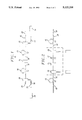
- FIG. 1 is a block diagram of an Erbium-doped fiber amplifier having at least two stages of amplification in accordance with the principles of the invention
- FIG. 2 is a block diagram of another embodiment of structure in accordance with the principles of the invention.
- FIG. 3 is a block diagram of still another embodiment of structure in accordance with the principles of the invention.
- Rare earth doped fibers for amplifying weak signals for both local and trunk optical telecommunications networks are of particular interest because of their low insertion loss, broad gain bandwidth and polarization insensitive gain.
- the doped optical fiber is normally transversely coupled to a pump so that a weak optical input signal at some wavelength within the rare earth gain profile experiences a desired amplification.
- Pump light which can be coupled into the optical fiber via a directional coupler may propagate either co-directionally or contra-directionally within the fiber relative to the signal.
- the directional coupler can have a high coupling ratio at the pump wavelength and a low coupling ratio at the signal wavelength.
- Erbium-doped optical amplifiers when used as power amplifiers, repeaters and preamplifiers in lightwave systems have been responsible for significant improvement in the performance of long-distance transmission systems, networks, CATV distribution and the like. Important features of these amplifiers include high gain (>40 dB), low noise (near quantum limit) and high saturated output power (>10 dBm).
- all optical systems utilize relatively simple single-stage amplifiers in combination with ancillary passive components such as isolators, pump multiplexers, and power monitors which are attached to either end of the fiber amplifier. This arrangement not only leads to rather stringent design and fabrication tolerances for a high-performance optical amplifier, but it prevents the exploitation of several unique properties of Erbium-doped fiber amplifiers.
- an optical fiber amplifier comprises multiple stages of amplification.
- the optical amplifier 10 comprises two separate and distinct stages of amplification separated by an optical means which can be a passive optical element such as an optical isolator.
- the first stage of amplification 12 is coupled to a second stage of amplification 14 through an optical means such as a passive element 16 which can be an optical isolator, an optical filter or the like.
- the first stage 12 can comprise a doped amplifying fiber 18 coupled via a coupler 20 to both an input port 22 for receiving a signal which is to be amplified and to a pump port 24 for receiving energy from a laser diode pump 26.
- Coupler 20 can be a multiplex (demultiplex) type of filter or an optical interference filter manufactured by, for example, JDS Optics of Ottawa, Canada.
- the second stage 14 of the multi-stage amplifier can comprise a second doped amplifying fiber 14 coupled via a coupler 28 to both an output port 30 for providing a signal which has been amplified and to a pump port 32 for receiving energy from a laser diode pump 34.
- coupler 28 can be a multiplex (demultiplex) type of filter or an optical interference filter manufactured by, for example, JDS Optics, a company located in Ottawa, Canada.
- the output port 36 of the fiber 18 is coupled to the input port 38 of the fiber 19 via a passive optical element 16.
- the optical element 16 can be an optical isolator or an optical filter or both.
- the optical isolator can take the form of an optical diode which permits optical energy to travel from the first stage 12 to the second stage 14 but restricts the travel of optical energy in the opposite direction.
- the optical filter can take the form of a multiplexer which can be made from a, a diffraction grating, a thin film, or a filter which can restrict the amplified spontaneous emission (ASE) and/or has filtering characteristics for modifying the gain characteristics of the multi-stage amplifier or other type of filter which reduces energy in the form of spontaneous emission from flowing between the two stages and causing saturation of either stage.
- the optical isolator and or the optical filter can be coupled to the optical fibers of the first stage 12 and the second stage 14 either optically, by fusion, by splicing or by other means.
- Light from laser diode pump 26 can be launched into the first stage 18 via a lens located at the pump port 24.
- a filter such as a holographic grating 39 can be formed in the fiber between the end 24 and the coupler 20 to reject an undesired mode from the laser diode pump by providing the required backscattering.
- coupler 20 is constructed to couple both the input signal received by input port 22 and the pump signal received by pump port 24 to amplifying fiber 18.
- coupler 28 is constructed to pass the amplified signal from the multi-stage amplifier to the output port 30 and to couple the pump signal received by pump port 32 to amplifying fiber 14.
- the laser diode pump 34 described above can generate a primary signal having a wavelength of 1.48 ⁇ m. It is to be noted, however, that the diode pump which generates a signal having a wavelength of 0.98 ⁇ m can also be used. When a laser diode pump which generates a signal having a wavelength of 0.98 ⁇ m is used, the problems associated with having undesired modes in the 1.50-1.55 ⁇ m wavelength are not normally present.
- an optical signal which is to be amplified is coupled by some convenient means such as, for example, optically or the like to input port 22 and a pump signal is coupled to pump port 24 and pump port 32.
- the received optical signal amplified by the Erbium-doped fiber amplifier 18 of the first stage 12 of the optical fiber amplifier 10 is coupled to the input port of the second stage 14 of the optical amplifier 10 via a passive optical element.
- the Erbium-doped fiber amplifier 18 of the first stage 12 can be pumped from either or both ends and that the Erbium-doped fiber amplifier 19 of the second stage 14 can also be pumped from either or both ends.
- the laser diode and a multiplexer for pumping the first and second stages 12, 14 of the optical amplifier 10 can be fabricated on a single substrate and, that substrate can include the passive optical element or elements such as an optical isolator and/or an optical filter.
- an Erbium-doped fiber amplifier By providing an optical amplifier which has two stages of amplification rather than only one, an Erbium-doped fiber amplifier is obtained which provides enhanced performance.
- the total pump power into the amplifier was less than 50 mW from two 1480 nm pump laser diodes.
- the positioning of one or more optical filters between the first and second stages of the multi-stage optical amplifier permits the gain spectrum to be controlled without significantly increasing amplifier noise as occurs when filters are placed at the input of a single stage amplifier or loss of saturated output power when the filters are placed at the output of a single stage amplifier.
- By positioning the filters between stages not only are these deleterious effects avoided, but self saturation by ASE is greatly reduced.
- the multi-stage amplifier becomes more robust than an equivalent single stage amplifier. For example, the multi-stage amplifier becomes less sensitive to transmission fiber reflections or internal reflections that cause oscillations or undesirable noise.
- a two-stage amplifier requires only one isolator whereas a single stage amplifier requires two isolators.
- the first stage can be operated as a low noise front end amplifier stage and the second stage can be operated as the power stage.
- This embodiment permits the second stage to be operated with a slightly higher noise to signal ratio without materially degrading the signal.
- FIG. 2 there is illustrated another embodiment of structure in accordance with the principles of the invention.
- the couplers for coupling the laser diode pumps and the passive optical elements such as the optical isolator and/or optical filter are located between the first stage of amplification and the second stage of amplification.
- the laser diode pump, couplers and passive optical elements can be on a single chip which can be conveniently located.
- an input port 40 of the first stage 12 of the multi-stage amplifier can be coupled either optically or by splicing, to a transmission fiber to receive an optical signal which is to be amplified.
- the output port 42 of the first stage 12 is coupled to coupler 20 either optically or by splicing.
- Coupler 20 couples a pump signal from a laser diode to the amplifying fiber 18 and also couples the amplified signal from the first amplifier stage 12 to an optical isolator 15.
- Isolator 15 which can be an optical diode, permits optical energy to travel from the first stage 12 to the second stage 14, but restricts the travel of optical energy in the opposite direction.
- the signal from the optical isolator can be connected to an optical filter 17 before passing through coupler 28 to the input port 44 of the second stage 14 of the multi-stage amplifier.
- the optical filter restricts energy in the form of spontaneous emission from the first stage 12 from reaching and causing saturation of the second stage 14 of amplification.
- Coupler 28 couples a pump signal from a laser diode to amplifying fiber 19 and also couples the amplified signal passed by isolator 15 and filter 17 to the input port of the second stage 14 of the multi-stage amplifier.
- the output port 30 of the multi-stage amplifier can be coupled, either optically, by splicing or the like to a transmission fiber 50.
- Couplers 20, 28, the isolator 15, filter 17 and laser diode pumps are positioned within a dashed box to indicate that they can be part of a common chip.
- FIG. 3 there is illustrated still another embodiment of structure in accordance with the principles of the invention for amplifying two discrete signals which are being transmitted in opposite directions.
- an amplified signal which is to be amplified is coupled to the input port 40 of the first stage 12 of the multi-stage amplifier 10.
- Coupler 20 couples a pump signal from a laser diode pump to amplifying fiber 18 and couples the amplified signal from the first stage 12 to a coupler 21.
- the amplified signal from the first stage 12 received by coupler 21 is directed to optical isolator 15.
- isolator 15 permits optical energy to travel from the first stage 12 to the second stage 14, but restricts optical energy from traveling in the opposite direction.
- optical filter 17 The signal from the optical isolator 15 is directed through optical filter 17, optical coupler 25 which can be similar to optical coupler 21, and optical coupler 28 which can be similar to optical coupler 20.
- Coupler 28 couples a pump signal from a laser diode pump and the amplified signal from the first stage 12 to the input port of amplifying fiber 19.
- An optical isolator 52 in tandem with an optical filter 54 is coupled between optical filters 21, 25.
- a first optical signal of a first wavelength which is received at port 40 of stage 12 of multi-stage amplifier 10 is first amplified in stage 12, then passes through couplers 20, 21, isolator 15, filter 17, coupler 25, coupler 28 and stage 14 where it is again amplified before arriving at port 30 for transmission along transmission fiber 50.
- a second optical signal of a second wavelength which is received at port 30 of stage 14 of multistage amplifier 10 is first amplified in stage 14. The amplified signal then passes through couplers 28, 25, isolator 52, filter 54, couplers 21 and 20 and stage 12 where it is again amplified before arriving at port 40 for transmission along transmission fiber 56.
- optical filter 17 is designed to pass the amplified signal received from stage 12 and to block the amplified signal received from stage 14.
- optical filter 52 is designed to pass the amplified signal received from stage 14 and to block the amplified signal received from stage 12.
- Couplers 21 and 25 can be dichroic couplers, 3 dB couplers or other type of couplers. Thus, substantially 50% of the signal from stage 12 is passed through coupler 21 to isolator 15 and the remaining signal is passed through to filter 54 and isolator 52 where it is blocked. In a similar manner, substantially 50% of the signal from stage 14 is passed through coupler 25 to isolator 52 and the remaining signal is passed through to filter 17 where it is blocked.
- Pump energy for stage 12 is obtained from laser diode 26 coupled to coupler 20; and, pump energy for stage 14 is obtained from laser diode 34 coupled to coupler 28.
- Locating a coupler 58, which can be a 3 dB coupler, between the laser diodes 26, 34 and the couplers 20, 28 permits the laser diodes to provide pump power to each stage either simultaneously, sequentially or alternately.
- signals obtained from couplers 21 and 25 can be used to monitor the operation of the stages of the multi-stage amplifier 10.
- An advantage of the embodiment of FIG. 3 is low input loss and high output saturation power and gain for signals being transmitted in two directions.
Abstract
This invention relates to an Erbium-doped fiber amplifier having multiple stages of amplification for providing enhanced performance. More specifically, optical means is located intermediate first and second stages of doped optical amplifying fibers adapted to receive a pump signal at a pump wavelength where the optical means is adapted to modify the net gain characteristics of the multi-stage amplifier. Presently, all known Erbium-doped fiber amplifiers utilize relatively simple single stage amplifiers which support required ancillary optically passive components such as isolators, filters, pump multiplexers, power monitors and the like at either end of the amplifier. This requirement of having the passive optical element at an end of thhe optical amplifier not only lends to relatively stringent design and fabrication tolerances for a high performance optical amplifier, but it restricts the design of the Erbium-doped fiber amplifier to an embodiment which prevents exploitation of the various unique properties of the Erbium-doped fiber amplifier.
Description
This application is a continuation of application Ser. No. 07/530,665, filed on May 30, 1990 now abandoned.
This invention relates generally to optical amplifiers for lightwave communications and more particularly to an Erbium-doped optical fiber amplifier having more than a single stage of amplification.
There is considerable interest in using rate earth doped fiber amplifiers to amplify weak optical signals for both local and trunk optical telecommunications networks. The rare earth doped optical amplifying fibers are found to be low in cost, exhibit low-noise, have a relatively large gain bandwidth which is not polarization dependent, exhibit substantially reduced crosstalk problems and display low insertion losses at the relevant operating wavelengths, for example, approximately 1.55 μm which are used in optical communications. A rare earth doped optical fiber amplifier can be coupled end-to-end to a transmission fiber and a laser diode pump, through an optical multiplexer. The optical multiplexer is designed to combine the signal which is to be amplified and the output from the laser diode pump with low loss. When the amplifying medium is excited with the optical power from the pump laser, signal light traversing the amplifier experiences gain. The pump energy may be made to propagate either co-directionally or contra-directionally relative to the signal energy, the direction of travel of the signal from the pump depending upon the noise requirements of the amplifier and whether any remaining unconverted pump light can be more conveniently filtered at the receiving end or transmitting end of the optical amplifier.
A complicating factor in the design of rare earth doped optical amplifiers involves the difference between the various parameters necessary to optimize the performance of the amplifier and those necessary to optimize the performance of the transmission system from end-to-end. In a transmission fiber, the spacing between repeaters, can be increased by minimizing loss in the fiber to reduce optical power requirements and by minimizing the fiber dispersion. However, in the amplifying fiber, as opposed to the transmission fiber, the major concern involves high gain, high saturation power and low noise, all with minimal pump powers. Additionally, because the signal mode size between the two fibers can be significantly different, splicing losses due to mode mismatch of the two fibers might be significant.
Currently, Erbium-doped fiber amplifiers appear to have the greatest potential for the high amplification necessary to overcome losses in the signal path including those of the various optical elements associated with the optical amplifier. Erbium-doped fiber amplifiers operate at λ=1.53-1.56 μm which is of particular interest for optical communication systems because, in this wavelength region, the amplifiers exhibit low insertion loss, broad gain bandwidth (approximately 30 nm) and polarization insensitive gain. Such amplifiers, for example, when pumped at λ=1.48 μm can have a gain as high as 35 dB but require as much as 70 mW of launched pump power. A higher gain together with a lower value of pump power is preferred.
This invention relates to an Erbium-doped fiber amplifier having multiple stages of amplification for providing enhanced performance. More specifically, optical means is located intermediate first and second stages of doped optical amplifying fibers adapted to receive a pump signal at a pump wavelength where the optical means is adapted to modify the net gain characteristics of the multi-stage amplifier. Presently, all known Erbium-doped fiber amplifiers utilize relatively simple single stage amplifiers which support required ancillary optically passive components such as isolators, filters, pump multiplexers, power monitors and the like at either end of the amplifier. This requirement of having the passive optical element at an end of the optical amplifier not only lends to relatively stringent design and fabrication tolerances for a high performance optical amplifier, but it restricts the design of the Erbium-doped fiber amplifier to an embodiment which prevents exploitation of the various unique properties of the Erbium-doped fiber amplifier.
FIG. 1 is a block diagram of an Erbium-doped fiber amplifier having at least two stages of amplification in accordance with the principles of the invention;
FIG. 2 is a block diagram of another embodiment of structure in accordance with the principles of the invention; and
FIG. 3 is a block diagram of still another embodiment of structure in accordance with the principles of the invention.
In the various FIGS. of the drawing, similar parts have similar reference numerals.
Rare earth doped fibers for amplifying weak signals for both local and trunk optical telecommunications networks are of particular interest because of their low insertion loss, broad gain bandwidth and polarization insensitive gain. In use, the doped optical fiber is normally transversely coupled to a pump so that a weak optical input signal at some wavelength within the rare earth gain profile experiences a desired amplification. Pump light which can be coupled into the optical fiber via a directional coupler may propagate either co-directionally or contra-directionally within the fiber relative to the signal. The directional coupler can have a high coupling ratio at the pump wavelength and a low coupling ratio at the signal wavelength.
Erbium-doped optical amplifiers when used as power amplifiers, repeaters and preamplifiers in lightwave systems have been responsible for significant improvement in the performance of long-distance transmission systems, networks, CATV distribution and the like. Important features of these amplifiers include high gain (>40 dB), low noise (near quantum limit) and high saturated output power (>10 dBm). At the present time, all optical systems utilize relatively simple single-stage amplifiers in combination with ancillary passive components such as isolators, pump multiplexers, and power monitors which are attached to either end of the fiber amplifier. This arrangement not only leads to rather stringent design and fabrication tolerances for a high-performance optical amplifier, but it prevents the exploitation of several unique properties of Erbium-doped fiber amplifiers.
Following the teaching of this invention, enhanced performance of Erbium-doped fiber amplifiers is obtained when an optical fiber amplifier comprises multiple stages of amplification. Referring to FIG. 1, there is illustrated a multi-stage optical amplifier in accordance with the principles of the invention. The optical amplifier 10 comprises two separate and distinct stages of amplification separated by an optical means which can be a passive optical element such as an optical isolator. The first stage of amplification 12 is coupled to a second stage of amplification 14 through an optical means such as a passive element 16 which can be an optical isolator, an optical filter or the like. The first stage 12 can comprise a doped amplifying fiber 18 coupled via a coupler 20 to both an input port 22 for receiving a signal which is to be amplified and to a pump port 24 for receiving energy from a laser diode pump 26. Coupler 20 can be a multiplex (demultiplex) type of filter or an optical interference filter manufactured by, for example, JDS Optics of Ottawa, Canada.
The second stage 14 of the multi-stage amplifier can comprise a second doped amplifying fiber 14 coupled via a coupler 28 to both an output port 30 for providing a signal which has been amplified and to a pump port 32 for receiving energy from a laser diode pump 34. Similar to the first stage, coupler 28 can be a multiplex (demultiplex) type of filter or an optical interference filter manufactured by, for example, JDS Optics, a company located in Ottawa, Canada.
The output port 36 of the fiber 18 is coupled to the input port 38 of the fiber 19 via a passive optical element 16. The optical element 16 can be an optical isolator or an optical filter or both. The optical isolator can take the form of an optical diode which permits optical energy to travel from the first stage 12 to the second stage 14 but restricts the travel of optical energy in the opposite direction. The optical filter can take the form of a multiplexer which can be made from a, a diffraction grating, a thin film, or a filter which can restrict the amplified spontaneous emission (ASE) and/or has filtering characteristics for modifying the gain characteristics of the multi-stage amplifier or other type of filter which reduces energy in the form of spontaneous emission from flowing between the two stages and causing saturation of either stage. The optical isolator and or the optical filter can be coupled to the optical fibers of the first stage 12 and the second stage 14 either optically, by fusion, by splicing or by other means.
Light from laser diode pump 26 can be launched into the first stage 18 via a lens located at the pump port 24. A filter such as a holographic grating 39 can be formed in the fiber between the end 24 and the coupler 20 to reject an undesired mode from the laser diode pump by providing the required backscattering.
As noted above, the coupler 20 is constructed to couple both the input signal received by input port 22 and the pump signal received by pump port 24 to amplifying fiber 18. In a similar manner, coupler 28 is constructed to pass the amplified signal from the multi-stage amplifier to the output port 30 and to couple the pump signal received by pump port 32 to amplifying fiber 14.
The laser diode pump 34 described above can generate a primary signal having a wavelength of 1.48 μm. It is to be noted, however, that the diode pump which generates a signal having a wavelength of 0.98 μm can also be used. When a laser diode pump which generates a signal having a wavelength of 0.98 μm is used, the problems associated with having undesired modes in the 1.50-1.55 μm wavelength are not normally present.
In operation, an optical signal which is to be amplified is coupled by some convenient means such as, for example, optically or the like to input port 22 and a pump signal is coupled to pump port 24 and pump port 32. The received optical signal amplified by the Erbium-doped fiber amplifier 18 of the first stage 12 of the optical fiber amplifier 10 is coupled to the input port of the second stage 14 of the optical amplifier 10 via a passive optical element.
It is to be understood that the Erbium-doped fiber amplifier 18 of the first stage 12 can be pumped from either or both ends and that the Erbium-doped fiber amplifier 19 of the second stage 14 can also be pumped from either or both ends. This being so, the laser diode and a multiplexer for pumping the first and second stages 12, 14 of the optical amplifier 10 can be fabricated on a single substrate and, that substrate can include the passive optical element or elements such as an optical isolator and/or an optical filter.
By providing an optical amplifier which has two stages of amplification rather than only one, an Erbium-doped fiber amplifier is obtained which provides enhanced performance. For example, a multi-stage Erbium-doped optical amplifier has been built which had a 1 nm bandwidth with 46.4 dB fiber-to-fiber gain at 1533 nm,>7 dBm output power at 3 dB gain saturation and nsp =3.25. The total pump power into the amplifier was less than 50 mW from two 1480 nm pump laser diodes. The positioning of one or more optical filters between the first and second stages of the multi-stage optical amplifier permits the gain spectrum to be controlled without significantly increasing amplifier noise as occurs when filters are placed at the input of a single stage amplifier or loss of saturated output power when the filters are placed at the output of a single stage amplifier. By positioning the filters between stages, not only are these deleterious effects avoided, but self saturation by ASE is greatly reduced. Thus, with this invention there is an increase of the efficiency of the conversion of pump light into signal photons. Additionally, by placing an optical isolator between two stages of a multi-stage Erbium-doped fiber amplifier rather than at an end, the multi-stage amplifier becomes more robust than an equivalent single stage amplifier. For example, the multi-stage amplifier becomes less sensitive to transmission fiber reflections or internal reflections that cause oscillations or undesirable noise. Furthermore, in many applications, a two-stage amplifier requires only one isolator whereas a single stage amplifier requires two isolators.
Another important advantage of the disclosed multi-stage optical amplifier is that very good conversion of pump light into signal light can be obtained to provide very high gain. Additionally, in the invention disclosed, the first stage can be operated as a low noise front end amplifier stage and the second stage can be operated as the power stage. This embodiment permits the second stage to be operated with a slightly higher noise to signal ratio without materially degrading the signal.
Referring to FIG. 2, there is illustrated another embodiment of structure in accordance with the principles of the invention. In the embodiment of FIG. 2 the couplers for coupling the laser diode pumps and the passive optical elements such as the optical isolator and/or optical filter are located between the first stage of amplification and the second stage of amplification. With this arrangement, the laser diode pump, couplers and passive optical elements can be on a single chip which can be conveniently located. In FIG. 2, an input port 40 of the first stage 12 of the multi-stage amplifier can be coupled either optically or by splicing, to a transmission fiber to receive an optical signal which is to be amplified. The output port 42 of the first stage 12 is coupled to coupler 20 either optically or by splicing. Coupler 20 couples a pump signal from a laser diode to the amplifying fiber 18 and also couples the amplified signal from the first amplifier stage 12 to an optical isolator 15. Isolator 15, which can be an optical diode, permits optical energy to travel from the first stage 12 to the second stage 14, but restricts the travel of optical energy in the opposite direction. The signal from the optical isolator can be connected to an optical filter 17 before passing through coupler 28 to the input port 44 of the second stage 14 of the multi-stage amplifier. The optical filter restricts energy in the form of spontaneous emission from the first stage 12 from reaching and causing saturation of the second stage 14 of amplification. Coupler 28 couples a pump signal from a laser diode to amplifying fiber 19 and also couples the amplified signal passed by isolator 15 and filter 17 to the input port of the second stage 14 of the multi-stage amplifier. The output port 30 of the multi-stage amplifier can be coupled, either optically, by splicing or the like to a transmission fiber 50. Couplers 20, 28, the isolator 15, filter 17 and laser diode pumps are positioned within a dashed box to indicate that they can be part of a common chip.
Referring to FIG. 3, there is illustrated still another embodiment of structure in accordance with the principles of the invention for amplifying two discrete signals which are being transmitted in opposite directions. In FIG. 3, an amplified signal which is to be amplified is coupled to the input port 40 of the first stage 12 of the multi-stage amplifier 10. Coupler 20 couples a pump signal from a laser diode pump to amplifying fiber 18 and couples the amplified signal from the first stage 12 to a coupler 21. The amplified signal from the first stage 12 received by coupler 21 is directed to optical isolator 15. As in FIG. 2, isolator 15 permits optical energy to travel from the first stage 12 to the second stage 14, but restricts optical energy from traveling in the opposite direction. The signal from the optical isolator 15 is directed through optical filter 17, optical coupler 25 which can be similar to optical coupler 21, and optical coupler 28 which can be similar to optical coupler 20. Coupler 28 couples a pump signal from a laser diode pump and the amplified signal from the first stage 12 to the input port of amplifying fiber 19. An optical isolator 52 in tandem with an optical filter 54 is coupled between optical filters 21, 25.
In operation, a first optical signal of a first wavelength which is received at port 40 of stage 12 of multi-stage amplifier 10 is first amplified in stage 12, then passes through couplers 20, 21, isolator 15, filter 17, coupler 25, coupler 28 and stage 14 where it is again amplified before arriving at port 30 for transmission along transmission fiber 50. A second optical signal of a second wavelength which is received at port 30 of stage 14 of multistage amplifier 10 is first amplified in stage 14. The amplified signal then passes through couplers 28, 25, isolator 52, filter 54, couplers 21 and 20 and stage 12 where it is again amplified before arriving at port 40 for transmission along transmission fiber 56.
In FIG. 3, optical filter 17 is designed to pass the amplified signal received from stage 12 and to block the amplified signal received from stage 14. Similarly, optical filter 52 is designed to pass the amplified signal received from stage 14 and to block the amplified signal received from stage 12.
Pump energy for stage 12 is obtained from laser diode 26 coupled to coupler 20; and, pump energy for stage 14 is obtained from laser diode 34 coupled to coupler 28. Locating a coupler 58, which can be a 3 dB coupler, between the laser diodes 26, 34 and the couplers 20, 28 permits the laser diodes to provide pump power to each stage either simultaneously, sequentially or alternately.
In some instances, a need may exist to monitor the operation of the multi-stage amplifier. Referring to FIG. 3, signals obtained from couplers 21 and 25 can be used to monitor the operation of the stages of the multi-stage amplifier 10.
An advantage of the embodiment of FIG. 3 is low input loss and high output saturation power and gain for signals being transmitted in two directions.
Claims (2)
1. A multi-stage optical amplifier comprising a first stage of amplification comprising an Erbium-doped optical amplifying fiber having a first port and a second port and lacking an isolator, a second stage of amplification comprising an Erbium-doped optical amplifying fiber having a first port and a second port and lacking an isolator,
a first coupler coupled to the second port of said first stage of amplification,
a second coupler coupled to the first port of said second stage of amplification,
means for generating a pump signal at a pump wavelength coupled to said first stage of amplification through said first coupler and to said second stage of amplification through said second coupler,
a third coupler interposed between said first coupler and said second coupler,
a fourth coupler interposed between said third coupler and said second coupler,
a first optical isolator and a first optical filter interposed between said third and fourth couplers to pass a signal of a first wavelength from first stage of amplification to said second stage of amplification, and
a second optical isolator and a second optical filter interposed between said third and fourth couplers to pass a signal of a second wavelength from said second stage of amplification to said first stage of amplification.
2. The multi-stage optical amplifier of claim 1 wherein said third and fourth couplers comprises 3 dB couplers, said first and second optical isolators comprise optical diodes, said first and second optical filters comprise interference filters, and said means for generating a pump signal comprises a laser diode.
Priority Applications (1)
| Application Number | Priority Date | Filing Date | Title |
|---|---|---|---|
| US07/686,013 US5115338A (en) | 1990-05-30 | 1991-04-12 | Multi-stage optical amplifier |
Applications Claiming Priority (2)
| Application Number | Priority Date | Filing Date | Title |
|---|---|---|---|
| US53066590A | 1990-05-30 | 1990-05-30 | |
| US07/686,013 US5115338A (en) | 1990-05-30 | 1991-04-12 | Multi-stage optical amplifier |
Related Parent Applications (1)
| Application Number | Title | Priority Date | Filing Date |
|---|---|---|---|
| US53066590A Continuation | 1990-05-30 | 1990-05-30 |
Publications (1)
| Publication Number | Publication Date |
|---|---|
| US5115338A true US5115338A (en) | 1992-05-19 |
Family
ID=27063338
Family Applications (1)
| Application Number | Title | Priority Date | Filing Date |
|---|---|---|---|
| US07/686,013 Expired - Lifetime US5115338A (en) | 1990-05-30 | 1991-04-12 | Multi-stage optical amplifier |
Country Status (1)
| Country | Link |
|---|---|
| US (1) | US5115338A (en) |
Cited By (60)
| Publication number | Priority date | Publication date | Assignee | Title |
|---|---|---|---|---|
| US5185814A (en) * | 1989-07-13 | 1993-02-09 | British Telecommunications Public Limited Company | Optical fiber communications network including plural amplifiers with single pump source |
| US5223705A (en) * | 1992-08-12 | 1993-06-29 | At&T Bell Laboratories | Measurement of an optical amplifier parameter with polarization |
| US5233463A (en) * | 1990-07-16 | 1993-08-03 | Pirelli Cavi S.P.A. | Active fiber optical amplifier for a fiber optics telecommunication line |
| US5271024A (en) * | 1992-07-27 | 1993-12-14 | General Instrument Corporation | Optical fiber amplifier and laser with flattened gain slope |
| US5343320A (en) * | 1992-08-03 | 1994-08-30 | At&T Bell Laboratories | Pump laser control circuit for an optical transmission system |
| US5363234A (en) * | 1993-10-14 | 1994-11-08 | Corning Incorporated | Amplifier having pump fiber filter |
| US5367587A (en) * | 1991-11-08 | 1994-11-22 | Mitsubishi Denki Kabushiki Kaisha | Optical amplifier |
| US5406411A (en) * | 1993-10-14 | 1995-04-11 | Corning Incorporated | Fiber amplifier having efficient pump power utilization |
| US5416864A (en) * | 1990-11-20 | 1995-05-16 | British Telecommunications Public Limited Company | Optical fiber amplified tapping network and method using same |
| US5422754A (en) * | 1992-03-19 | 1995-06-06 | Fujitsu Limited | Optical transmission line relayed with multistage optical amplifiers |
| US5430572A (en) * | 1993-09-30 | 1995-07-04 | At&T Corp. | High power, high gain, low noise, two-stage optical amplifier |
| US5455704A (en) * | 1991-11-08 | 1995-10-03 | Mitsubishi Denki Kabushiki Kaisha | Optical-fiber light amplifier |
| US5485299A (en) * | 1993-07-31 | 1996-01-16 | Northern Telecom Limited | Communications system |
| US5500756A (en) * | 1992-02-28 | 1996-03-19 | Hitachi, Ltd. | Optical fiber transmission system and supervision method of the same |
| US5502591A (en) * | 1994-01-26 | 1996-03-26 | France Telecom Etablissement Autonome De Droit Public | Optical amplifier with a doped fluoride glass of optical fibre and process for producing said amplifier |
| US5510930A (en) * | 1993-07-19 | 1996-04-23 | Mitsubishi Denki Kabushiki Kaisha | Light amplifying apparatus |
| US5521753A (en) * | 1992-08-20 | 1996-05-28 | Hewlett-Packard Company | Multi-stage fibre amplifier |
| US5532870A (en) * | 1993-11-24 | 1996-07-02 | Sumitomo Electric Industries, Ltd. | Optical fiber amplifier and optical amplifier repeater |
| US5555118A (en) * | 1993-06-04 | 1996-09-10 | Ciena Corporation | Method for removing and inserting optical carriers in a WDM optical communication system |
| US5600473A (en) * | 1993-06-04 | 1997-02-04 | Ciena Corporation | Optical amplifier systems with add/drop multiplexing |
| US5677920A (en) * | 1994-09-06 | 1997-10-14 | Sdl, Inc. | Upconversion fiber laser |
| US5721635A (en) * | 1993-11-24 | 1998-02-24 | Sumitomo Electric Industries, Ltd. | Optical fiber amplifier and optical amplifier repeater |
| AU701698B2 (en) * | 1994-11-25 | 1999-02-04 | Sumitomo Electric Industries, Ltd. | Optical communication system |
| WO1999018476A1 (en) * | 1997-10-02 | 1999-04-15 | Nam Kyoo Park | Multi-stage fiber amplifier with flattened gain curves |
| US5915052A (en) * | 1997-06-30 | 1999-06-22 | Uniphase Telecommunications Products, Inc. | Loop status monitor for determining the amplitude of the signal components of a multi-wavelength optical beam |
| US5933552A (en) * | 1996-04-25 | 1999-08-03 | The Furukawa Electric Co., Ltd. | Optical filter, manufacturing method thereof and optical amplifier equipped with said optical filter |
| US5963361A (en) * | 1998-05-22 | 1999-10-05 | Ciena Corporation | Optical amplifier having a variable attenuator controlled based on detected ASE |
| WO1999050978A2 (en) * | 1998-04-01 | 1999-10-07 | Telefonaktiebolaget Lm Ericsson (Publ) | Optical fiber amplifier having a gain flattening filter |
| US5982964A (en) * | 1997-06-30 | 1999-11-09 | Uniphase Corporation | Process for fabrication and independent tuning of multiple integrated optical directional couplers on a single substrate |
| US5995277A (en) * | 1997-06-30 | 1999-11-30 | Samsung Electronics Co., Ltd. | Optical fiber amplifier with absorber |
| US6020986A (en) * | 1997-11-21 | 2000-02-01 | Jds Uniphase Corporation | Programmable add-drop module for use in an optical circuit |
| US6031849A (en) * | 1997-11-14 | 2000-02-29 | Jds Uniphase Corporation | High power three level fiber laser and method of making same |
| US6049413A (en) * | 1998-05-22 | 2000-04-11 | Ciena Corporation | Optical amplifier having first and second stages and an attenuator controlled based on the gains of the first and second stages |
| US6061173A (en) * | 1994-09-26 | 2000-05-09 | Fujitsu Limited | Wavelength-division-multiplexing optical amplifier |
| US6061171A (en) * | 1998-05-22 | 2000-05-09 | Ciena Corporation | Optical amplifier having a variable attenuator controlled based on input power |
| WO2000031839A1 (en) * | 1998-11-24 | 2000-06-02 | Samsung Electronics Co., Ltd. | Optical fiber amplifier for controlling gain flatness |
| US6151157A (en) * | 1997-06-30 | 2000-11-21 | Uniphase Telecommunications Products, Inc. | Dynamic optical amplifier |
| US6178276B1 (en) * | 1999-04-05 | 2001-01-23 | United States Of America As Represented By The Secretary Of The Army | End-pumped waveguide optical splitter-amplifiers based on self-imaging |
| US6198570B1 (en) * | 1996-04-05 | 2001-03-06 | The Furukawa Electric Co., Ltd. | Optical filter, manufacturing method thereof, and optical amplifier equipped with said optical filter |
| US6226424B1 (en) | 1997-09-19 | 2001-05-01 | Uniphase Telecommunications Products, Inc. | Integrated wavelength-select transmitter |
| EP1128581A1 (en) * | 2000-02-16 | 2001-08-29 | Nec Corporation | Optical amplifier with gain equalizer |
| US6310990B1 (en) | 2000-03-16 | 2001-10-30 | Cidra Corporation | Tunable optical structure featuring feedback control |
| US6332722B1 (en) | 1997-08-04 | 2001-12-25 | Pirelli Cavi E Sistemi S.P.A. | Method for optically connecting optical components in an optoelectronic rig, and optoelectronic rig constructed according to this method |
| US6362916B2 (en) | 1998-09-25 | 2002-03-26 | Fiver Laboratories | All fiber gain flattening optical filter |
| US6424457B1 (en) * | 2000-10-06 | 2002-07-23 | Onetta, Inc. | Optical amplifiers and methods for manufacturing optical amplifiers |
| US6483632B1 (en) * | 1996-06-26 | 2002-11-19 | Nortel Networks Limited | Multistage optical amplifier with gain flattening |
| US6583923B1 (en) * | 1999-12-07 | 2003-06-24 | Siemens Aktiengesellschaft | Optical fiber amplifier |
| US20030165007A1 (en) * | 2002-03-04 | 2003-09-04 | Sergey Frolov | Multistage optical amplifier having a fiber-based amplifier stage and a planar waveguide-based amplifier stage |
| WO2003079058A2 (en) * | 2002-03-15 | 2003-09-25 | Pd-Ld, Inc. | Fiber optic devices having volume bragg grating elements |
| US6636661B1 (en) * | 2002-02-26 | 2003-10-21 | Wavesplitter Technologies, Inc. | Optical signal interleaving comb filter with reduced chromatic dispersion and applications therefor |
| US20050018743A1 (en) * | 2003-07-03 | 2005-01-27 | Volodin Boris Leonidovich | Use of volume Bragg gratings for the conditioning of laser emission characteristics |
| US20050099930A1 (en) * | 2003-09-26 | 2005-05-12 | Volodin Boris L. | Methods for manufacturing volume bragg grating elements |
| US20060146896A1 (en) * | 2005-01-06 | 2006-07-06 | Lg Electronics Inc. | Laser optical apparatus |
| US20060171428A1 (en) * | 2005-02-03 | 2006-08-03 | Pd-Ld, Inc. | High-power, phased-locked, laser arrays |
| US20070165298A1 (en) * | 2003-08-13 | 2007-07-19 | Atsushi Seki | Optical amplifier apparatus |
| US20080253421A1 (en) * | 2004-01-20 | 2008-10-16 | Greg Charache | High-Power Semiconductor Laser |
| US7528385B2 (en) | 2002-03-15 | 2009-05-05 | Pd-Ld, Inc. | Fiber optic devices having volume Bragg grating elements |
| US20100164603A1 (en) * | 2008-12-30 | 2010-07-01 | Hafez Walid M | Programmable fuse and anti-fuse elements and methods of changing conduction states of same |
| US20110206074A1 (en) * | 2006-05-11 | 2011-08-25 | Michael Kevan Durkin | Apparatus for providing optical radiation |
| US8455157B1 (en) | 2007-04-26 | 2013-06-04 | Pd-Ld, Inc. | Methods for improving performance of holographic glasses |
Citations (8)
| Publication number | Priority date | Publication date | Assignee | Title |
|---|---|---|---|---|
| US3416089A (en) * | 1964-04-03 | 1968-12-10 | American Optical Corp | Laser amplifier construction |
| US3599106A (en) * | 1968-11-06 | 1971-08-10 | American Optical Corp | High intensity-high coherence laser system |
| US3949315A (en) * | 1972-10-03 | 1976-04-06 | Gunter Zeidler | Optical intermediate amplifier for a communication system |
| US4015217A (en) * | 1961-10-27 | 1977-03-29 | American Optical Corporation | Means for producing and amplifying optical energy |
| US4143332A (en) * | 1975-11-13 | 1979-03-06 | Compagnie Generale D'electricite S.A. | Wave-length selective cut-out device |
| US4859016A (en) * | 1983-11-25 | 1989-08-22 | The Board Of Trustees Of The Leland Stanford Junior University | Fiber optic amplifier |
| US4906949A (en) * | 1984-11-16 | 1990-03-06 | Thomson-Csf | Monomode optical source and an optical amplifying device tuneable in the near infra red and application to selective and regeneration amplifying devices |
| US4938556A (en) * | 1983-11-25 | 1990-07-03 | The Board Of Trustees Of The Leland Stanford Junior University | Superfluorescent broadband fiber laser source |
-
1991
- 1991-04-12 US US07/686,013 patent/US5115338A/en not_active Expired - Lifetime
Patent Citations (9)
| Publication number | Priority date | Publication date | Assignee | Title |
|---|---|---|---|---|
| US4015217A (en) * | 1961-10-27 | 1977-03-29 | American Optical Corporation | Means for producing and amplifying optical energy |
| US3416089A (en) * | 1964-04-03 | 1968-12-10 | American Optical Corp | Laser amplifier construction |
| US3599106A (en) * | 1968-11-06 | 1971-08-10 | American Optical Corp | High intensity-high coherence laser system |
| US3949315A (en) * | 1972-10-03 | 1976-04-06 | Gunter Zeidler | Optical intermediate amplifier for a communication system |
| US4143332A (en) * | 1975-11-13 | 1979-03-06 | Compagnie Generale D'electricite S.A. | Wave-length selective cut-out device |
| US4859016A (en) * | 1983-11-25 | 1989-08-22 | The Board Of Trustees Of The Leland Stanford Junior University | Fiber optic amplifier |
| US4938556A (en) * | 1983-11-25 | 1990-07-03 | The Board Of Trustees Of The Leland Stanford Junior University | Superfluorescent broadband fiber laser source |
| US4859016B1 (en) * | 1983-11-25 | 2000-11-07 | Univ Leland Stanford Junior | Fiber optic amplifier |
| US4906949A (en) * | 1984-11-16 | 1990-03-06 | Thomson-Csf | Monomode optical source and an optical amplifying device tuneable in the near infra red and application to selective and regeneration amplifying devices |
Non-Patent Citations (10)
| Title |
|---|
| Electronics Letters, May 10, 1990, vol. 26, No. 10, pp. 661 662. * |
| Electronics Letters, May 10, 1990, vol. 26, No. 10, pp. 661-662. |
| Giles et al; "2 GBit/ Signal Amplification . . . Amplifier"; J. Lightwave Tech., vol. 7, #4, pp. 651-656, May 1989, Abstract Supplied. |
| Giles et al; "Noise Performance of Erbrium-Doped . . . "; IBEB Photonics. Tech. Lett.; vol. 1, #11, pp. 367-369, Nov. 1989, Abstract Supplied. |
| Giles et al; 2 GBit/ Signal Amplification . . . Amplifier ; J. Lightwave Tech., vol. 7, 4, pp. 651 656, May 1989, Abstract Supplied. * |
| Giles et al; Noise Performance of Erbrium Doped . . . ; IBEB Photonics. Tech. Lett.; vol. 1, 11, pp. 367 369, Nov. 1989, Abstract Supplied. * |
| Mesuda et al; "High Gain Two Stage Amplification . . . "; Elect. Lett., vol. 26, #10, pp. 661-662, May 1, 1990. |
| Mesuda et al; High Gain Two Stage Amplification . . . ; Elect. Lett., vol. 26, 10, pp. 661 662, May 1, 1990. * |
| Olsson et al.; "Two-Stage High-Gain Optical Amplifier"; Journ. Lightwave Tech., vol 7, #5, May 1989, pp. 791-793. |
| Olsson et al.; Two Stage High Gain Optical Amplifier ; Journ. Lightwave Tech., vol 7, 5, May 1989, pp. 791 793. * |
Cited By (123)
| Publication number | Priority date | Publication date | Assignee | Title |
|---|---|---|---|---|
| US5185814A (en) * | 1989-07-13 | 1993-02-09 | British Telecommunications Public Limited Company | Optical fiber communications network including plural amplifiers with single pump source |
| US5233463A (en) * | 1990-07-16 | 1993-08-03 | Pirelli Cavi S.P.A. | Active fiber optical amplifier for a fiber optics telecommunication line |
| US5416864A (en) * | 1990-11-20 | 1995-05-16 | British Telecommunications Public Limited Company | Optical fiber amplified tapping network and method using same |
| US5367587A (en) * | 1991-11-08 | 1994-11-22 | Mitsubishi Denki Kabushiki Kaisha | Optical amplifier |
| US5455704A (en) * | 1991-11-08 | 1995-10-03 | Mitsubishi Denki Kabushiki Kaisha | Optical-fiber light amplifier |
| US5500756A (en) * | 1992-02-28 | 1996-03-19 | Hitachi, Ltd. | Optical fiber transmission system and supervision method of the same |
| US5568310A (en) * | 1992-03-19 | 1996-10-22 | Fujitsu Limited | Optical transmission line relayed with multistage optical amplifiers |
| US5422754A (en) * | 1992-03-19 | 1995-06-06 | Fujitsu Limited | Optical transmission line relayed with multistage optical amplifiers |
| US5271024A (en) * | 1992-07-27 | 1993-12-14 | General Instrument Corporation | Optical fiber amplifier and laser with flattened gain slope |
| US5343320A (en) * | 1992-08-03 | 1994-08-30 | At&T Bell Laboratories | Pump laser control circuit for an optical transmission system |
| US5223705A (en) * | 1992-08-12 | 1993-06-29 | At&T Bell Laboratories | Measurement of an optical amplifier parameter with polarization |
| US5521753A (en) * | 1992-08-20 | 1996-05-28 | Hewlett-Packard Company | Multi-stage fibre amplifier |
| US5579143A (en) * | 1993-06-04 | 1996-11-26 | Ciena Corporation | Optical system with tunable in-fiber gratings |
| US5600473A (en) * | 1993-06-04 | 1997-02-04 | Ciena Corporation | Optical amplifier systems with add/drop multiplexing |
| US5555118A (en) * | 1993-06-04 | 1996-09-10 | Ciena Corporation | Method for removing and inserting optical carriers in a WDM optical communication system |
| US5701186A (en) * | 1993-06-04 | 1997-12-23 | Ciena Corporation | Optical cable TV system |
| US5510930A (en) * | 1993-07-19 | 1996-04-23 | Mitsubishi Denki Kabushiki Kaisha | Light amplifying apparatus |
| US5485299A (en) * | 1993-07-31 | 1996-01-16 | Northern Telecom Limited | Communications system |
| US5430572A (en) * | 1993-09-30 | 1995-07-04 | At&T Corp. | High power, high gain, low noise, two-stage optical amplifier |
| US5363234A (en) * | 1993-10-14 | 1994-11-08 | Corning Incorporated | Amplifier having pump fiber filter |
| US5406411A (en) * | 1993-10-14 | 1995-04-11 | Corning Incorporated | Fiber amplifier having efficient pump power utilization |
| US5721635A (en) * | 1993-11-24 | 1998-02-24 | Sumitomo Electric Industries, Ltd. | Optical fiber amplifier and optical amplifier repeater |
| US5532870A (en) * | 1993-11-24 | 1996-07-02 | Sumitomo Electric Industries, Ltd. | Optical fiber amplifier and optical amplifier repeater |
| US5640269A (en) * | 1993-11-24 | 1997-06-17 | Sumitomo Electric Industries, Inc. | Optical fiber amplifier and optical amplifier repeater |
| US5502591A (en) * | 1994-01-26 | 1996-03-26 | France Telecom Etablissement Autonome De Droit Public | Optical amplifier with a doped fluoride glass of optical fibre and process for producing said amplifier |
| US5677920A (en) * | 1994-09-06 | 1997-10-14 | Sdl, Inc. | Upconversion fiber laser |
| US6061173A (en) * | 1994-09-26 | 2000-05-09 | Fujitsu Limited | Wavelength-division-multiplexing optical amplifier |
| AU701698B2 (en) * | 1994-11-25 | 1999-02-04 | Sumitomo Electric Industries, Ltd. | Optical communication system |
| US6198570B1 (en) * | 1996-04-05 | 2001-03-06 | The Furukawa Electric Co., Ltd. | Optical filter, manufacturing method thereof, and optical amplifier equipped with said optical filter |
| US5933552A (en) * | 1996-04-25 | 1999-08-03 | The Furukawa Electric Co., Ltd. | Optical filter, manufacturing method thereof and optical amplifier equipped with said optical filter |
| US6483632B1 (en) * | 1996-06-26 | 2002-11-19 | Nortel Networks Limited | Multistage optical amplifier with gain flattening |
| US5915052A (en) * | 1997-06-30 | 1999-06-22 | Uniphase Telecommunications Products, Inc. | Loop status monitor for determining the amplitude of the signal components of a multi-wavelength optical beam |
| US5982964A (en) * | 1997-06-30 | 1999-11-09 | Uniphase Corporation | Process for fabrication and independent tuning of multiple integrated optical directional couplers on a single substrate |
| US5995277A (en) * | 1997-06-30 | 1999-11-30 | Samsung Electronics Co., Ltd. | Optical fiber amplifier with absorber |
| US6151157A (en) * | 1997-06-30 | 2000-11-21 | Uniphase Telecommunications Products, Inc. | Dynamic optical amplifier |
| US6332722B1 (en) | 1997-08-04 | 2001-12-25 | Pirelli Cavi E Sistemi S.P.A. | Method for optically connecting optical components in an optoelectronic rig, and optoelectronic rig constructed according to this method |
| US6226424B1 (en) | 1997-09-19 | 2001-05-01 | Uniphase Telecommunications Products, Inc. | Integrated wavelength-select transmitter |
| US6370290B1 (en) | 1997-09-19 | 2002-04-09 | Uniphase Corporation | Integrated wavelength-select transmitter |
| WO1999018476A1 (en) * | 1997-10-02 | 1999-04-15 | Nam Kyoo Park | Multi-stage fiber amplifier with flattened gain curves |
| US6473549B1 (en) * | 1997-10-02 | 2002-10-29 | Samsung Electronics, Co., Ltd. | Multi-stage fiber amplifier with flattened gain curves |
| US6031849A (en) * | 1997-11-14 | 2000-02-29 | Jds Uniphase Corporation | High power three level fiber laser and method of making same |
| US6020986A (en) * | 1997-11-21 | 2000-02-01 | Jds Uniphase Corporation | Programmable add-drop module for use in an optical circuit |
| WO1999050978A2 (en) * | 1998-04-01 | 1999-10-07 | Telefonaktiebolaget Lm Ericsson (Publ) | Optical fiber amplifier having a gain flattening filter |
| US6414787B2 (en) | 1998-04-01 | 2002-07-02 | Telefonaktiebolaget Lm Ericsson | Optical fiber amplifier having a gain flattening filter |
| WO1999050978A3 (en) * | 1998-04-01 | 1999-12-02 | Ericsson Telefon Ab L M | Optical fiber amplifier having a gain flattening filter |
| US6061171A (en) * | 1998-05-22 | 2000-05-09 | Ciena Corporation | Optical amplifier having a variable attenuator controlled based on input power |
| US6049413A (en) * | 1998-05-22 | 2000-04-11 | Ciena Corporation | Optical amplifier having first and second stages and an attenuator controlled based on the gains of the first and second stages |
| US5963361A (en) * | 1998-05-22 | 1999-10-05 | Ciena Corporation | Optical amplifier having a variable attenuator controlled based on detected ASE |
| US6822786B2 (en) | 1998-09-25 | 2004-11-23 | Sdo Communications Corp. | All fiber gain flattening optical filter |
| US20020041434A1 (en) * | 1998-09-25 | 2002-04-11 | Weiti Wu | All fiber gain flattening optical filter |
| US6362916B2 (en) | 1998-09-25 | 2002-03-26 | Fiver Laboratories | All fiber gain flattening optical filter |
| WO2000031839A1 (en) * | 1998-11-24 | 2000-06-02 | Samsung Electronics Co., Ltd. | Optical fiber amplifier for controlling gain flatness |
| US6178276B1 (en) * | 1999-04-05 | 2001-01-23 | United States Of America As Represented By The Secretary Of The Army | End-pumped waveguide optical splitter-amplifiers based on self-imaging |
| US6583923B1 (en) * | 1999-12-07 | 2003-06-24 | Siemens Aktiengesellschaft | Optical fiber amplifier |
| EP1128581A1 (en) * | 2000-02-16 | 2001-08-29 | Nec Corporation | Optical amplifier with gain equalizer |
| US6600595B2 (en) | 2000-02-16 | 2003-07-29 | Nec Corporation | Multi-stage optical amplifier apparatus having fiber grating with a cutoff wavelength less than the pump light wavelength |
| US6310990B1 (en) | 2000-03-16 | 2001-10-30 | Cidra Corporation | Tunable optical structure featuring feedback control |
| US6563968B2 (en) | 2000-03-16 | 2003-05-13 | Cidra Corporation | Tunable optical structure featuring feedback control |
| US6424457B1 (en) * | 2000-10-06 | 2002-07-23 | Onetta, Inc. | Optical amplifiers and methods for manufacturing optical amplifiers |
| US6636661B1 (en) * | 2002-02-26 | 2003-10-21 | Wavesplitter Technologies, Inc. | Optical signal interleaving comb filter with reduced chromatic dispersion and applications therefor |
| US20030165007A1 (en) * | 2002-03-04 | 2003-09-04 | Sergey Frolov | Multistage optical amplifier having a fiber-based amplifier stage and a planar waveguide-based amplifier stage |
| US6865018B2 (en) | 2002-03-04 | 2005-03-08 | Inplane Photonics, Inc. | Multistage optical amplifier having a fiber-based amplifier stage and a planar waveguide-based amplifier stage |
| WO2003079058A2 (en) * | 2002-03-15 | 2003-09-25 | Pd-Ld, Inc. | Fiber optic devices having volume bragg grating elements |
| US7273683B2 (en) | 2002-03-15 | 2007-09-25 | Pd-Ld, Inc. | Fiber optic devices having volume bragg grating elements |
| US7949216B2 (en) | 2002-03-15 | 2011-05-24 | Pd-Ld, Inc. | Bragg grating elements for optical devices |
| US20050031264A1 (en) * | 2002-03-15 | 2005-02-10 | Pd-Ld, Inc. | Fiber optic devices having volume Bragg grating elements |
| US20030219205A1 (en) * | 2002-03-15 | 2003-11-27 | Volodin Boris L. | Fiber optic devices having volume bragg grating elements |
| US7817888B2 (en) | 2002-03-15 | 2010-10-19 | Pd-Ld, Inc. | Bragg grating elements for optical devices |
| US20050244102A1 (en) * | 2002-03-15 | 2005-11-03 | Pd-Ld, Inc. | Fiber optic devices having volume bragg grating elements |
| US20050265657A1 (en) * | 2002-03-15 | 2005-12-01 | Pd-Ld, Inc. | Fiber optic devices having volume bragg grating elements |
| US7031573B2 (en) | 2002-03-15 | 2006-04-18 | Pd-Ld, Inc. | Fiber optic devices having volume Bragg grating elements |
| US7528385B2 (en) | 2002-03-15 | 2009-05-05 | Pd-Ld, Inc. | Fiber optic devices having volume Bragg grating elements |
| US20090086297A1 (en) * | 2002-03-15 | 2009-04-02 | Pd-Ld, Inc. | Bragg grating elements for optical devices |
| US20060193571A1 (en) * | 2002-03-15 | 2006-08-31 | Volodin Boris L | Bragg grating elements for optical devices |
| US7125632B2 (en) | 2002-03-15 | 2006-10-24 | Pd-Ld, Inc. | Fiber optic devices having volume Bragg grating elements |
| US7477818B2 (en) | 2002-03-15 | 2009-01-13 | Pd-Ld, Inc. | Bragg grating elements for optical devices |
| WO2003079058A3 (en) * | 2002-03-15 | 2004-12-02 | Pd Ld Inc | Fiber optic devices having volume bragg grating elements |
| US20080267246A1 (en) * | 2003-07-03 | 2008-10-30 | Pd-Ld, Inc. | Apparatus And Methods For Altering A Characteristic Of A Light-Emitting Device |
| US20060256832A1 (en) * | 2003-07-03 | 2006-11-16 | Pd-Ld, Inc. | Chirped bragg grating elements |
| US20060256827A1 (en) * | 2003-07-03 | 2006-11-16 | Volodin Boris L | Use of bragg grating elements for the conditioning of laser emission characteristics |
| US20060256830A1 (en) * | 2003-07-03 | 2006-11-16 | Pd-Ld, Inc. | Bragg grating elements for the conditioning of laser emission characteristics |
| US20060256831A1 (en) * | 2003-07-03 | 2006-11-16 | Pd-Ld, Inc. | Use of volume bragg gratings for the conditioning of laser emission characteristics |
| US20070047608A1 (en) * | 2003-07-03 | 2007-03-01 | Pd-Ld, Inc. | Use of volume bragg gratings for the conditioning of laser emission characteristics |
| US10205295B2 (en) | 2003-07-03 | 2019-02-12 | Necsel Intellectual Property, Inc. | Chirped Bragg grating elements |
| US7248618B2 (en) | 2003-07-03 | 2007-07-24 | Pd-Ld, Inc. | Systems and methods for second harmonic generation using three-dimensional Bragg grating elements |
| US7248617B2 (en) | 2003-07-03 | 2007-07-24 | Pd-Ld, Inc. | Use of volume bragg gratings for the conditioning of laser emission characteristics |
| US20060251143A1 (en) * | 2003-07-03 | 2006-11-09 | Volodin Boris L | Apparatus and methods for altering a characteristic of light-emitting device |
| US7298771B2 (en) | 2003-07-03 | 2007-11-20 | Pd-Ld, Inc. | Use of volume Bragg gratings for the conditioning of laser emission characteristics |
| US9793674B2 (en) | 2003-07-03 | 2017-10-17 | Necsel Intellectual Property, Inc. | Chirped Bragg grating elements |
| US7397837B2 (en) | 2003-07-03 | 2008-07-08 | Pd-Ld, Inc. | Apparatus and methods for altering a characteristic of a light-emitting device |
| US8306088B2 (en) | 2003-07-03 | 2012-11-06 | Pd-Ld, Inc. | Bragg grating elements for the conditioning of laser emission characteristics |
| US20080253424A1 (en) * | 2003-07-03 | 2008-10-16 | Boris Leonidovich Volodin | Use of Volume Bragg Gratings For The Conditioning Of Laser Emission Characteristics |
| US20050018743A1 (en) * | 2003-07-03 | 2005-01-27 | Volodin Boris Leonidovich | Use of volume Bragg gratings for the conditioning of laser emission characteristics |
| US20060251142A1 (en) * | 2003-07-03 | 2006-11-09 | Pd-Ld, Inc. | Apparatus and methods for altering a characteristic of a light-emitting device |
| US20060251134A1 (en) * | 2003-07-03 | 2006-11-09 | Volodin Boris L | Apparatus and methods for altering a characteristic of a light-emitting device |
| US7796673B2 (en) | 2003-07-03 | 2010-09-14 | Pd-Ld, Inc. | Apparatus and methods for altering a characteristic of a light-emitting device |
| US7697589B2 (en) | 2003-07-03 | 2010-04-13 | Pd-Ld, Inc. | Use of volume Bragg gratings for the conditioning of laser emission characteristics |
| US7545844B2 (en) | 2003-07-03 | 2009-06-09 | Pd-Ld, Inc. | Use of Bragg grating elements for the conditioning of laser emission characteristics |
| US7590162B2 (en) | 2003-07-03 | 2009-09-15 | Pd-Ld, Inc. | Chirped bragg grating elements |
| US7633985B2 (en) | 2003-07-03 | 2009-12-15 | Pd-Ld, Inc. | Apparatus and methods for altering a characteristic of light-emitting device |
| US7609437B2 (en) * | 2003-08-13 | 2009-10-27 | Advantest Corporation | Optical amplifier apparatus |
| US20070165298A1 (en) * | 2003-08-13 | 2007-07-19 | Atsushi Seki | Optical amplifier apparatus |
| US7391703B2 (en) | 2003-09-26 | 2008-06-24 | Pd-Ld, Inc. | Methods for manufacturing volume Bragg grating elements |
| US7792003B2 (en) | 2003-09-26 | 2010-09-07 | Pd-Ld, Inc. | Methods for manufacturing volume Bragg grating elements |
| US20080225672A1 (en) * | 2003-09-26 | 2008-09-18 | Pd-Ld, Inc. | Methods For Manufacturing Volume Bragg Grating Elements |
| US20050099930A1 (en) * | 2003-09-26 | 2005-05-12 | Volodin Boris L. | Methods for manufacturing volume bragg grating elements |
| US7889776B2 (en) | 2004-01-20 | 2011-02-15 | Trumpf Photonics Inc. | High-power semiconductor laser |
| US20080253421A1 (en) * | 2004-01-20 | 2008-10-16 | Greg Charache | High-Power Semiconductor Laser |
| US20060146896A1 (en) * | 2005-01-06 | 2006-07-06 | Lg Electronics Inc. | Laser optical apparatus |
| US7596157B2 (en) * | 2005-01-06 | 2009-09-29 | Lg Electronics Inc. | Laser optical apparatus |
| US20060171428A1 (en) * | 2005-02-03 | 2006-08-03 | Pd-Ld, Inc. | High-power, phased-locked, laser arrays |
| US7949030B2 (en) | 2005-02-03 | 2011-05-24 | Pd-Ld, Inc. | High-power, phased-locked, laser arrays |
| US9130349B2 (en) | 2005-02-03 | 2015-09-08 | Pd-Ld, Inc. | High-power, phase-locked, laser arrays |
| US8340150B2 (en) | 2005-02-03 | 2012-12-25 | Pd-Ld, Inc. | High-power, phase-locked, laser arrays |
| US9748730B2 (en) | 2005-02-03 | 2017-08-29 | Necsel Intellectual Property, Inc. | High-power, phased-locked, laser arrays |
| US8755421B2 (en) | 2005-02-03 | 2014-06-17 | Pd-Ld, Inc. | High-power, phase-locked, laser arrays |
| US9379514B2 (en) | 2005-02-03 | 2016-06-28 | Pd-Ld, Inc. | High-power, phased-locked, laser arrays |
| US20110216790A1 (en) * | 2006-05-11 | 2011-09-08 | Michael Kevan Durkin | Apparatus for providing optical radiation |
| US20110206074A1 (en) * | 2006-05-11 | 2011-08-25 | Michael Kevan Durkin | Apparatus for providing optical radiation |
| US9377757B2 (en) | 2007-04-26 | 2016-06-28 | Pd-Ld, Inc. | Methods for improving performance of holographic glasses |
| US9120696B2 (en) | 2007-04-26 | 2015-09-01 | Pd-Ld, Inc. | Methods for improving performance of holographic glasses |
| US8455157B1 (en) | 2007-04-26 | 2013-06-04 | Pd-Ld, Inc. | Methods for improving performance of holographic glasses |
| US20100164603A1 (en) * | 2008-12-30 | 2010-07-01 | Hafez Walid M | Programmable fuse and anti-fuse elements and methods of changing conduction states of same |
Similar Documents
| Publication | Publication Date | Title |
|---|---|---|
| US5115338A (en) | Multi-stage optical amplifier | |
| US5253104A (en) | Balanced optical amplifier | |
| US5831754A (en) | Optical amplifier | |
| US6104527A (en) | High efficiency bandwidth doubled and gain flattened silica fiber amplifier | |
| US6310716B1 (en) | Amplifier system with a discrete Raman fiber amplifier module | |
| KR100312013B1 (en) | Fiber Optic Amplifier with Efficient Pump Power Characteristics | |
| US5808786A (en) | Optical fiber amplifying device and method therefor | |
| JP2999376B2 (en) | Optical fiber amplifier | |
| JPH07176817A (en) | Optical signal amplifier | |
| US5822113A (en) | Optical amplifier using optical circulator and fiber amplifier | |
| JPH04250429A (en) | Optical fiber amplifier | |
| EP1235370A2 (en) | Bi-directional optical-amplifier module | |
| US6469826B1 (en) | Optical amplifier | |
| EP0459685A2 (en) | Multi-stage optical amplifier | |
| US5548438A (en) | Bidirectional optical amplifier | |
| US6952308B2 (en) | Multi-stage bidirectional optical amplifier | |
| US20030179442A1 (en) | Gain flattening optical fiber amplifier | |
| KR100446541B1 (en) | Dispersion-compensated raman optical fiber amplifier | |
| US6504647B1 (en) | Optical fiber amplifier, a method of amplifying optical signals, optical communications system | |
| JP2002217477A (en) | Optical amplifier | |
| US6807373B1 (en) | Multiband Raman amplifier | |
| Delavaux et al. | High performance Er-Yb planar waveguide amplifiers as in-line and pre-amplifiers in 10 Gb/s fiber system experiments | |
| JP3290707B2 (en) | Optical amplifier | |
| JP2737596B2 (en) | Optical fiber amplifier | |
| JP3317722B2 (en) | Optical fiber amplifier |
Legal Events
| Date | Code | Title | Description |
|---|---|---|---|
| STCF | Information on status: patent grant |
Free format text: PATENTED CASE |
|
| FEPP | Fee payment procedure |
Free format text: PAYOR NUMBER ASSIGNED (ORIGINAL EVENT CODE: ASPN); ENTITY STATUS OF PATENT OWNER: LARGE ENTITY |
|
| FPAY | Fee payment |
Year of fee payment: 4 |
|
| FEPP | Fee payment procedure |
Free format text: PAYOR NUMBER ASSIGNED (ORIGINAL EVENT CODE: ASPN); ENTITY STATUS OF PATENT OWNER: LARGE ENTITY Free format text: PAYER NUMBER DE-ASSIGNED (ORIGINAL EVENT CODE: RMPN); ENTITY STATUS OF PATENT OWNER: LARGE ENTITY |
|
| FPAY | Fee payment |
Year of fee payment: 8 |
|
| FPAY | Fee payment |
Year of fee payment: 12 |