US5183116A - Variable pressure regulator for extended fire-extinguishing system - Google Patents
Variable pressure regulator for extended fire-extinguishing system Download PDFInfo
- Publication number
- US5183116A US5183116A US07/728,358 US72835891A US5183116A US 5183116 A US5183116 A US 5183116A US 72835891 A US72835891 A US 72835891A US 5183116 A US5183116 A US 5183116A
- Authority
- US
- United States
- Prior art keywords
- pressure
- fire
- inlet
- extinguishing material
- regulated
- Prior art date
- Legal status (The legal status is an assumption and is not a legal conclusion. Google has not performed a legal analysis and makes no representation as to the accuracy of the status listed.)
- Expired - Lifetime
Links
Images


Classifications
-
- A—HUMAN NECESSITIES
- A62—LIFE-SAVING; FIRE-FIGHTING
- A62C—FIRE-FIGHTING
- A62C3/00—Fire prevention, containment or extinguishing specially adapted for particular objects or places
- A62C3/07—Fire prevention, containment or extinguishing specially adapted for particular objects or places in vehicles, e.g. in road vehicles
- A62C3/08—Fire prevention, containment or extinguishing specially adapted for particular objects or places in vehicles, e.g. in road vehicles in aircraft
-
- A—HUMAN NECESSITIES
- A62—LIFE-SAVING; FIRE-FIGHTING
- A62C—FIRE-FIGHTING
- A62C31/00—Delivery of fire-extinguishing material
-
- A—HUMAN NECESSITIES
- A62—LIFE-SAVING; FIRE-FIGHTING
- A62C—FIRE-FIGHTING
- A62C37/00—Control of fire-fighting equipment
- A62C37/36—Control of fire-fighting equipment an actuating signal being generated by a sensor separate from an outlet device
- A62C37/38—Control of fire-fighting equipment an actuating signal being generated by a sensor separate from an outlet device by both sensor and actuator, e.g. valve, being in the danger zone
- A62C37/40—Control of fire-fighting equipment an actuating signal being generated by a sensor separate from an outlet device by both sensor and actuator, e.g. valve, being in the danger zone with electric connection between sensor and actuator
-
- G—PHYSICS
- G05—CONTROLLING; REGULATING
- G05D—SYSTEMS FOR CONTROLLING OR REGULATING NON-ELECTRIC VARIABLES
- G05D16/00—Control of fluid pressure
- G05D16/04—Control of fluid pressure without auxiliary power
- G05D16/10—Control of fluid pressure without auxiliary power the sensing element being a piston or plunger
- G05D16/103—Control of fluid pressure without auxiliary power the sensing element being a piston or plunger the sensing element placed between the inlet and outlet
-
- Y—GENERAL TAGGING OF NEW TECHNOLOGICAL DEVELOPMENTS; GENERAL TAGGING OF CROSS-SECTIONAL TECHNOLOGIES SPANNING OVER SEVERAL SECTIONS OF THE IPC; TECHNICAL SUBJECTS COVERED BY FORMER USPC CROSS-REFERENCE ART COLLECTIONS [XRACs] AND DIGESTS
- Y10—TECHNICAL SUBJECTS COVERED BY FORMER USPC
- Y10T—TECHNICAL SUBJECTS COVERED BY FORMER US CLASSIFICATION
- Y10T137/00—Fluid handling
- Y10T137/7722—Line condition change responsive valves
- Y10T137/7781—With separate connected fluid reactor surface
- Y10T137/7784—Responsive to change in rate of fluid flow
- Y10T137/7787—Expansible chamber subject to differential pressures
- Y10T137/7788—Pressures across fixed choke
-
- Y—GENERAL TAGGING OF NEW TECHNOLOGICAL DEVELOPMENTS; GENERAL TAGGING OF CROSS-SECTIONAL TECHNOLOGIES SPANNING OVER SEVERAL SECTIONS OF THE IPC; TECHNICAL SUBJECTS COVERED BY FORMER USPC CROSS-REFERENCE ART COLLECTIONS [XRACs] AND DIGESTS
- Y10—TECHNICAL SUBJECTS COVERED BY FORMER USPC
- Y10T—TECHNICAL SUBJECTS COVERED BY FORMER US CLASSIFICATION
- Y10T137/00—Fluid handling
- Y10T137/7722—Line condition change responsive valves
- Y10T137/7781—With separate connected fluid reactor surface
- Y10T137/7793—With opening bias [e.g., pressure regulator]
- Y10T137/7808—Apertured reactor surface surrounds flow line
Definitions
- the original approach to protecting the cargo space was to have two or more agent containers, each having sufficient agent to produce a concentration greatly in excess of that required for extinguishing a fire in the cargo space.
- These containers which were rapid discharge containers, would be discharged sequentially at predetermined time intervals.
- the first container would be discharged at the onset of a fire to raise the concentration of fire-extinguishing material in the cargo space to about 8%-10%. This concentration would decay due to leakage of fire-extinguishing material from the cargo space.
- a second container would be fired, again producing a concentration of 8%-10%. This method of keeping a fire suppressed proved inefficient in that it requires more fire-extinguishing material than is necessary to keep the fire suppressed.
- Most fire extinguishing systems include at least two containers --one for rapid discharge of the fire extinguishing material and one for extended discharge of the fire extinguishing material. Both containers are normally disposed outside the cargo space and are subject to temperatures between -65° F. and 170° F.
- the rapid discharge container is designed to rapidly release the fire-extinguishing material so as to obtain, in a short time period, a concentration in the cargo space sufficient to extinguish or "knock-down" the fire.
- the extended discharge container is designed to release the fire-extinguishing material at a much slower rate in order to keep the concentration of fire-extinguishing material in the cargo space at a predetermined value to prevent the fire from reoccurring. Without the extended discharge, the concentration of fire-extinguishing material in the cargo space could drop below what is necessary to keep the fire suppressed and embers could reignite the fire.
- Variations in the mass flow rate of fire-extinguishing material in an extended discharge system is potentially hazardous. If the mass flow rate is too low to maintain an adequate concentration of fire-extinguishing material in the cargo space the fire could reoccur. Conversely, if the mass flow rate is too high, then the fire-extinguishing material could be depleted before the flight is completed. This possibility would require the extended discharge container to be grossly over-sized to provide an adequate safety margin resulting in higher costs and greater weight to be carried.
- the present invention is an extended discharge system for aircraft which compensates for temperature variations to maintain the mass flow rate of fire-extinguishing material within a predetermined, optimal range at any temperature.
- the extended discharge system includes a container filled with a fire-extinguishing material, a discharge nozzle connected to the extended discharge container, and a variable pressure controller interconnected between the extended discharge container and the discharge nozzle.
- the variable pressure controller produces a variable regulated pressure which varies as a function of the inlet pressure to the controller.
- the variable pressure controller uses a sliding piston to vary the size of a variable orifice between an inlet chamber and a control chamber.
- the inlet pressure within the inlet chamber acts on the piston tending to enlarge the variable orifice.
- the regulated pressure, or the pressure in the control chamber acts on the piston tending t close the variable orifice.
- the piston will assume a position which restricts the flow of fire-extinguishing material between the inlet chamber and the control chamber.
- force balance on the piston is upset causing the piston to move toward a more open position.
- the pressure drop across the orifice will decrease until a new force balance is established.
- the variable orifice will open to a point that it no longer restricts the flow of fire-extinguishing material between the inlet chamber and regulated pressure chamber. Below this threshold pressure, there will be no regulation of the pressure.
- Another object of the present invention is to provide an extended discharge system having a variable pressure controller which provides a variable regulated pressure as a function of the inlet pressure to the controller.
- Still another object of the present invention is to provide an extended discharge system which is effective in keeping a fire aboard an aircraft suppressed for the duration of the aircraft's flight.
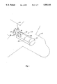
- FIG. 1 is a schematic diagram of a fire-extinguishing system incorporating the extended discharge system of the present invention.
- FIG. 2 is a graph illustrating the performance of a prior art extended discharge system using a constant pressure regulator in series with a fixed orifice.
- FIG. 3 is a graph illustrating the performance of a prior art extended discharge system having a fixed orifice and no pressure regulation.
- FIG. 4 is an elevation view of an extended discharge container with a portion thereof shown in section.
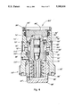
- FIG. 5 is a longitudinal sectional view of the variable pressure controller used in the extended discharge system.
- FIG. 6 is a longitudinal sectional view of a second embodiment of the variable pressure controller used in the extended discharge system.
- FIG. 7 is a graph illustrating the performance of the extended discharge system of the present invention.
- the fire-extinguishing system 10 is used for suppressing a fire in a cargo bay 14 of an aircraft 12.
- the fire-extinguishing system includes a rapid discharge system 16 and an extended discharge system 22.
- the rapid discharge system includes at least one container 17 connected by line 18 to discharge,nozzles 20.
- the fire-extinguishing material from the container 17 is rapidly discharged to obtain a relatively high concentration of fire-extinguishing material sufficient to extinguish the fire.
- the extended discharge system 22 includes in the cargo bay 14 at least one container 24 connected by line 26 to the extended discharge nozzles 28.
- the extended discharge container 24 is adapted to slowly release fire-extinguishing material to prevent the fire from reflaming. More particularly, the extended discharge container 24 releases an amount of fire-extinguishing material sufficient to compensate for any loss of concentration in the cargo bay 14 due to leakage. Thus, the concentration of fire extinguishing material within the cargo bay 14 can be maintained at a sufficient level to keep the fire suppressed.
- the extended discharge systems have discharged the fire-extinguishing material through a fixed orifice or have used a constant pressure regulator in series with a fixed orifice. It has been discovered that the mass flow rate of fire-extinguishing material from the extended discharge container in prior art devices will vary greatly depending upon the temperature of the fire-extinguishing material.
- the graph shown in FIG. 2 illustrates the operation of an extended discharged system with a fixed pressure regulator set at 50 lbs/in 2 in series with a fixed orifice. The system represented in the graph is currently in use in commercial aircraft. The graph illustrates the rate at which the fire-extinguishing material is discharged at different temperatures.
- the system was tested at temperatures of -54° F., 70° F., and 164° F. As can be clearly seen, the mass flow rate of the fire-extinguishing material varied widely depending on the temperature.
- a second test was conducted in an extended discharge system with a single fixed orifice and no pressure regulation. The system was tested at temperatures of -66° F., -25° F., 70° F., 135° F., and 164° F. The results of this test are shown in FIG. 3. As can be seen in the graph, the system without any pressure regulation produced better results than the system with constant pressure regulation. Nevertheless, the extended discharge system with the single fixed orifice produced a mass flow rate which varied by approximately 40 % depending on the temperature of the fire-extinguishing material.
- the present invention is designed to obtain a far greater degree of consistency in the mass flow rate of fire-extinguishing material in an extended discharge system.
- a more consistent mass flow rate is achieved by using a variable pressure controller in series with a fixed orifice.
- the pressure controller produces a regulated pressure as a function of the inlet pressure to the regulator.
- the relationship of the inlet pressure to the regulated pressure was selected based on empirical studies conducted to produce a constant mass flow rate over a wide range of temperatures.
- the extended discharge container 24 includes a generally cylindrical tank 30.
- a pressure switch fitting 32 and fill fitting 34 are disposed in the upper portions of the tank 30 which is hermetically sealed around the fittings.
- Four mounting lugs 36 are welded to the circumference of the tank 30 for mounting the container 24 in the aircraft.
- An exhaust fitting 38 is disposed at the lower end of the tank 30 and the tank 30 is hermetically sealed around the fitting 38.
- the variable pressure controller 50 is inserted into the exhaust fitting 38 and projects into the lower regions of the tank 30.
- a frangible burst disk 40 is fitted inside the exhaust fitting 38 and is also hermetically sealed around its outer periphery to the inside of the exhaust fitting 38.
- a sleeve adapter 42 is threaded onto the outer circumference of the exhaust fitting 38.
- a standard discharge head 44 slides over the adapter sleeve 42 and is secured by a nut 45 which engages threads on the discharge head 44.
- the discharge head 44 includes a cartridge 46 which is connected to the electrical connector 48. When a fire is detected, the cartridge 46 is fired into the frangible burst disk 40 to rupture the disk 40. Once the disk 40 is ruptured, the fire-extinguishing material flows through the variable pressure controller 50 into the discharge head 44. From the discharge head 44, the fire-extinguishing material is directed through line 26 to the discharge nozzles 28 at a predetermined mass flow rate needed to maintain an adequate concentration of fire-extinguishing material in the cargo bay 14 to keep the fire suppressed.
- the variable pressure controller 50 includes a housing 52 having an inlet chamber 54, a control chamber 60, and an exhaust chamber 62.
- the control chamber 60 is larger in diameter than the inlet chamber 54 so as to define a shoulder 56.
- the housing 50 is open at both ends.
- the end adjacent the control chamber 60 is enclosed by means of a piston stop 86 which is held by a retaining ring 90.
- An o-ring 92 is inserted into a circumferential groove 94 formed in the housing 52 to prevent leakage of fire-extinguishing material around the piston stop 86.
- the opposite end is enclosed by a spring cap 98.
- the spring cap 98 includes an externally threaded skirt 100 which engages corresponding threads formed internally in the exhaust chamber 62 of the housing 52.
- the spring cap 98 also includes exhaust ports 104 through which the fire-extinguishing material exits the controller 50.
- a piston bore 64 extends axially through the housing 52 between the inlet chamber 54 and exhaust chamber 62.
- a piston 66 having an outwardly projecting flange 68 is slidably mounted in the piston bore 64 for controlling the flow of fire-extinguishing material through the controller 50.
- the piston 66 includes a seat member 70 made of nylon material and having a conical outer surface 72 which is held in place by a retaining ring 74.
- the conical surface 72 of the seat member 70 in combination with the shoulder 56, defines a variable orifice 58 communicating between the inlet chamber 54 and control chamber 60.
- An o-ring 67 extends around the circumference of the piston to prevent leakage of fluid around the piston 66 from the inlet chamber 54 to the exhaust chamber 62.
- An internal passageway 76 is formed inside the piston 66 and communicates between the control chamber 60 and exhaust chamber 62. Fluid in the control chamber 60 passes through the piston 66 into the exhaust chamber 62.
- a restrictor 78 is inserted into the internal passageway 76 of the piston 66.
- the restrictor 78 includes a filter 80 in series with a fixed orifice 82 for metering the fire-extinguishing material flowing through the piston 66.
- the piston 66 is biased against the stop 86 by a spring 96.
- the spring 96 is retained by the spring cap 98.
- One end of the spring 96 is inserted into the skirt 100.
- the opposite end of the spring 96 pushes against a spring plate 102 which engages the end of the piston 66 to bias the piston 66 toward a less restrictive position.
- pressurized fire-extinguishing material enters the inlet section 54 through the inlet 53.
- a screen is provided over the inlet 53 to prevent particulate matter from entering the controller 50.
- These fluids ar forced through the variable orifice 58 between the shoulder 56 and the conical surface 72 of the seat member 70 into the control chamber 60.
- a reduction in pressure is effected by restriction of the flow of fire-extinguishing material through the variable orifice 58.
- the effective area A 1 of the piston 66 acted on by the inlet pressure P i is less than the effective area A 2 of the piston 66 acted on by the regulated pressure P R .
- the ratio of these areas A 1 and A 2 plus the force of the spring 96 is such that the net force exerted on the piston 66 by the regulated pressure P R will always exceed the net force exerted on the piston 66 by the inlet pressure.
- the pressure controller 50 will always try to maintain a force balance according to the following equation:
- K the force exerted by the spring on the piston.
- the inlet pressure P i to the controller 50 will decrease.
- the decrease in the inlet pressure P i will upset the force balance on the piston 66 causing the piston 66 to move towards a more open position.
- the area of the variable orifice 58 increases, there will be less restriction on the flow of fluid between the inlet chamber 54 and control chamber 60 so that the pressure differential will also decrease.
- a predetermined threshold pressure is reached, the difference between the force exerted by the regulated pressure on the piston 66 and the force exerted by the inlet pressure on the piston 66 will be insufficient to counterbalance the spring force.
- the piston 66 will be urged to an extreme open position as shown in FIG. 5.
- the controller 50 will not regulate the pressure.
- This threshold pressure is determined by the spring force exerted on the piston 66 and can be changed by either tightening or loosening the spring cap 98.
- the inlet pressure P i to the controller 50 will increase.
- the increase in the inlet pressure P i will upset the force balance on the piston 66 causing the piston 66 to move towards a more restrictive position.
- the area of the variable orifice 58 decreases, there will be more restriction on the flow of fluid between the inlet chamber 54 and control chamber 60 so that the pressure differential will also increase.
- the pressure controller 50 of the present invention compensates for pressure and density variation resulting from changes in the temperature of the fire-extinguishing material over the operational range of the controller.
- the mass flow rate of fire-extinguishing material at -65° F. will be roughly equal to the mass flow rate of fire-extinguishing material at 160° F.
- variable pressure regulator 50' includes a housing 52' having an inlet chamber 54', a control chamber 60', and an exhaust chamber 62'.
- the control chamber 60' is larger in diameter than the inlet chamber 54' so as to define a shoulder 56'.
- the housing 52' is open at both ends.
- the end adjacent the control chamber 60' is enclosed by means of a piston stop 86' which is held by a retaining ring 90'.
- An o-ring 92' is inserted into a circumferential groove 94' formed in the housing 52' to prevent leakage of fire-extinguishing material around the piston stop 86'.
- the opposite end is enclosed by an end cap 88'.
- the end cap 88' is externally threaded and engages corresponding threads formed internally in the exhaust chamber 62' of the housing 52'.
- the end cap 88' includes exhaust ports 89' through which the fire-extinguishing material exits the controller 50'.
- a piston 66' is movably mounted in the housing 52'.
- the piston 66' includes a removable seat 70' disposed around the main body chamber 68' of the piston 66' which is held in place by a washer 73' and retaining ring 74'.
- the seat 70' includes a conical surface 72' which is disposed with respect to the shoulder 56' of the housing 52' so as to define a variable size orifice 58'.
- An internal passageway 76' is formed in the piston 66' which communicates between the control chambers 60' and exhaust chamber 62'.
- a restrictor 78' is disposed in the internal passageway 76' of the piston 66'.
- the restrictor 78' includes a filter 80' in series with a fixed orifice 82' for metering the fire-extinguishing material flowing through the piston 66'.
- the piston 66' is biased against the stop 86' by a bellows 96'.
- the bellows 96' is secured at one end to a bellows stop 98' which is secured in the housing 52' by a roll pin 100'. Leakage of gas around the bellows stop 98' is prevented by an o-ring 102' which is disposed in a circumferential groove 104' formed in the housing 52'.
- the neck 67' of the piston extends into the bellows 96' which keeps the piston 66' centered in the housing 52'.
- the bellows 96' also functions to keep fluid from flowing between the inlet chamber 54' and the exhaust chamber 62'.
- the embodiment shown in FIG. 6 functions in the same manner as the previous embodiment.
- the fire-extinguishing material enters the inlet chamber 54' through the inlet 53'. Fluid must then pass through the variable orifice 58' into the control chamber 60'.
- the flow of fluid will be restricted as the fluid passes through the variable orifice 58' resulting in a pressure differential between the fluid in the inlet chamber 54' and the fluid in the control chamber 60' .
- the force balance on the piston 66' is upset causing the piston 66' to move toward a less restricted position.
- the pressure differential between the inlet chamber 54' and the control chamber 60' will decrease.
- variable orifice 58' will open to a point that it no longer restricts the flow of fire-extinguishing material between the inlet chamber 54' and the control chamber 60'. Below this threshold pressure, there will be no regulation of the pressure.
- variable pressure regulator according to the present invention when used in a extended discharged system produces a mass flow rate which remains relatively constant over a wide range of temperatures.
- a prototype of the system was tested and the results of the test are shown in FIG. 7.
- the extended discharge system of the present invention produced a more consistent flow rate over a wide range of temperatures than the prior art extended discharge systems.
- variations in flow rate between temperatures of -70° to 160° can be kept within ⁇ 5% of a predetermined mass flow rate needed to keep the fire within a cargo space of an airplane suppressed.
Abstract
Description
PA.sub.2 =P.sub.i A.sub.1 +K
Claims (17)
Priority Applications (3)
| Application Number | Priority Date | Filing Date | Title |
|---|---|---|---|
| US07/728,358 US5183116A (en) | 1991-07-11 | 1991-07-11 | Variable pressure regulator for extended fire-extinguishing system |
| AU23246/92A AU2324692A (en) | 1991-07-11 | 1992-07-09 | Variable pressure regulator for extended fire-extinguishing system |
| PCT/US1992/005915 WO1993000961A1 (en) | 1991-07-11 | 1992-07-09 | Variable pressure regulator for extended fire-extinguishing system |
Applications Claiming Priority (1)
| Application Number | Priority Date | Filing Date | Title |
|---|---|---|---|
| US07/728,358 US5183116A (en) | 1991-07-11 | 1991-07-11 | Variable pressure regulator for extended fire-extinguishing system |
Publications (1)
| Publication Number | Publication Date |
|---|---|
| US5183116A true US5183116A (en) | 1993-02-02 |
Family
ID=24926524
Family Applications (1)
| Application Number | Title | Priority Date | Filing Date |
|---|---|---|---|
| US07/728,358 Expired - Lifetime US5183116A (en) | 1991-07-11 | 1991-07-11 | Variable pressure regulator for extended fire-extinguishing system |
Country Status (3)
| Country | Link |
|---|---|
| US (1) | US5183116A (en) |
| AU (1) | AU2324692A (en) |
| WO (1) | WO1993000961A1 (en) |
Cited By (15)
| Publication number | Priority date | Publication date | Assignee | Title |
|---|---|---|---|---|
| US5344077A (en) * | 1992-09-14 | 1994-09-06 | Terry Roy D A | Apparatus for delivering compressed particulate solid fire fighting agent |
| US5578993A (en) * | 1994-11-28 | 1996-11-26 | Autronics Corporation | Temperature compensated annunciator |
| US5582014A (en) * | 1993-12-15 | 1996-12-10 | American Airlines, Inc. | Halon recovery system |
| US6003608A (en) * | 1997-12-08 | 1999-12-21 | Fail Safe Safety Systems, Inc. | Fire suppression system for an enclosed space |
| US6024174A (en) * | 1997-12-12 | 2000-02-15 | Pierce; Lauvon | Sprinkler head and a temperature controlled valve therefor |
| US6053256A (en) * | 1998-07-17 | 2000-04-25 | Pacific Scientific Company | Fire extinguishing system |
| US6102127A (en) * | 1997-12-12 | 2000-08-15 | Pierce; Lauvon | Temperature controlled valve for drip valves and sprinkler systems |
| US20040020665A1 (en) * | 2002-07-31 | 2004-02-05 | Alankar Gupta | Helium gas total flood fire suppression system |
| EP1547651A1 (en) * | 2003-12-24 | 2005-06-29 | Airbus Deutschland GmbH | Fire extinguishing device and method in particular for cargo spaces in aircrafts |
| US20140102732A1 (en) * | 2010-10-29 | 2014-04-17 | Leonard K. Parker | Pressure Assisted Variable Flow Clean Throat Aerial Retardant Delivery System |
| US20150297922A1 (en) * | 2014-04-16 | 2015-10-22 | Kidde Technologies, Inc. | Fire suppression flow control system apparatus and system |
| WO2017218011A1 (en) * | 2016-06-17 | 2017-12-21 | Ametek Ameron, Llc | Fire metering protection system for aircraft |
| WO2019087147A1 (en) * | 2017-11-03 | 2019-05-09 | Bombardier Inc. | Aircraft fire suppression system |
| US10352801B2 (en) * | 2016-05-10 | 2019-07-16 | Fike Corporation | Intelligent temperature and pressure gauge assembly |
| WO2021025929A1 (en) * | 2019-08-02 | 2021-02-11 | ETG FIRE, Inc. | Extended discharge fire suppression systems and methods |
Families Citing this family (4)
| Publication number | Priority date | Publication date | Assignee | Title |
|---|---|---|---|---|
| US5704797A (en) * | 1994-05-19 | 1998-01-06 | Tii Industries, Inc. | Switchable electrical socket |
| AU712134B2 (en) * | 1996-09-04 | 1999-10-28 | Chin Kwee Ong | Fire extinguishing system |
| US9463344B2 (en) * | 2014-04-29 | 2016-10-11 | Kidde Technologies, Inc. | Bellows actuated temperature compensated pressure switching apparatus and system |
| US10420969B2 (en) * | 2017-10-17 | 2019-09-24 | Kidde Technologies, Inc. | Commercial aviation fire extinguisher—strength increase method for in service and OEM fire protection |
Citations (2)
| Publication number | Priority date | Publication date | Assignee | Title |
|---|---|---|---|---|
| US4643260A (en) * | 1985-09-26 | 1987-02-17 | The Boeing Company | Fire suppression system with controlled secondary extinguishant discharge |
| US5038867A (en) * | 1986-05-07 | 1991-08-13 | Mbb | Fire protection of cargo spaces |
-
1991
- 1991-07-11 US US07/728,358 patent/US5183116A/en not_active Expired - Lifetime
-
1992
- 1992-07-09 AU AU23246/92A patent/AU2324692A/en not_active Abandoned
- 1992-07-09 WO PCT/US1992/005915 patent/WO1993000961A1/en active Application Filing
Patent Citations (2)
| Publication number | Priority date | Publication date | Assignee | Title |
|---|---|---|---|---|
| US4643260A (en) * | 1985-09-26 | 1987-02-17 | The Boeing Company | Fire suppression system with controlled secondary extinguishant discharge |
| US5038867A (en) * | 1986-05-07 | 1991-08-13 | Mbb | Fire protection of cargo spaces |
Cited By (26)
| Publication number | Priority date | Publication date | Assignee | Title |
|---|---|---|---|---|
| US5344077A (en) * | 1992-09-14 | 1994-09-06 | Terry Roy D A | Apparatus for delivering compressed particulate solid fire fighting agent |
| US5582014A (en) * | 1993-12-15 | 1996-12-10 | American Airlines, Inc. | Halon recovery system |
| US5578993A (en) * | 1994-11-28 | 1996-11-26 | Autronics Corporation | Temperature compensated annunciator |
| US6003608A (en) * | 1997-12-08 | 1999-12-21 | Fail Safe Safety Systems, Inc. | Fire suppression system for an enclosed space |
| US6024174A (en) * | 1997-12-12 | 2000-02-15 | Pierce; Lauvon | Sprinkler head and a temperature controlled valve therefor |
| US6102127A (en) * | 1997-12-12 | 2000-08-15 | Pierce; Lauvon | Temperature controlled valve for drip valves and sprinkler systems |
| US6053256A (en) * | 1998-07-17 | 2000-04-25 | Pacific Scientific Company | Fire extinguishing system |
| US6935433B2 (en) | 2002-07-31 | 2005-08-30 | The Boeing Company | Helium gas total flood fire suppression system |
| US20040020665A1 (en) * | 2002-07-31 | 2004-02-05 | Alankar Gupta | Helium gas total flood fire suppression system |
| US7434628B2 (en) | 2003-12-24 | 2008-10-14 | Airbus Deutschland Gmbh | Method and apparatus for extinguishing a fire in an enclosed space |
| DE10361020A1 (en) * | 2003-12-24 | 2005-08-04 | Airbus Deutschland Gmbh | Fire-extinguishing apparatus and method, in particular for firefighting cargo compartments of aircraft |
| US20050139366A1 (en) * | 2003-12-24 | 2005-06-30 | Alexander Scheidt | Method and apparatus for extinguishing a fire in an enclosed space |
| EP1547651A1 (en) * | 2003-12-24 | 2005-06-29 | Airbus Deutschland GmbH | Fire extinguishing device and method in particular for cargo spaces in aircrafts |
| DE10361020B4 (en) * | 2003-12-24 | 2010-09-30 | Airbus Deutschland Gmbh | Fire fighting equipment |
| US9180325B2 (en) * | 2010-10-29 | 2015-11-10 | Leonard K. Parker | Pressure assisted aerial retardant delivery system |
| US8820422B2 (en) * | 2010-10-29 | 2014-09-02 | Leonard K. Parker | Pressure assisted aerial retardant delivery system |
| US20140367128A1 (en) * | 2010-10-29 | 2014-12-18 | Leonard K. Parker | Pressure Assisted Aerial Retardant Delivery System |
| US20140102732A1 (en) * | 2010-10-29 | 2014-04-17 | Leonard K. Parker | Pressure Assisted Variable Flow Clean Throat Aerial Retardant Delivery System |
| US20150297922A1 (en) * | 2014-04-16 | 2015-10-22 | Kidde Technologies, Inc. | Fire suppression flow control system apparatus and system |
| US9440103B2 (en) * | 2014-04-16 | 2016-09-13 | Kidde Technologies, Inc. | Fire suppression flow control system apparatus and system |
| US9694221B2 (en) | 2014-04-16 | 2017-07-04 | Kidde Technologies, Inc. | Fire suppression flow control system apparatus and system |
| US10352801B2 (en) * | 2016-05-10 | 2019-07-16 | Fike Corporation | Intelligent temperature and pressure gauge assembly |
| WO2017218011A1 (en) * | 2016-06-17 | 2017-12-21 | Ametek Ameron, Llc | Fire metering protection system for aircraft |
| WO2019087147A1 (en) * | 2017-11-03 | 2019-05-09 | Bombardier Inc. | Aircraft fire suppression system |
| WO2021025929A1 (en) * | 2019-08-02 | 2021-02-11 | ETG FIRE, Inc. | Extended discharge fire suppression systems and methods |
| US11298573B2 (en) | 2019-08-02 | 2022-04-12 | ETG FIRE, Inc. | Extended discharge fire suppression systems and methods |
Also Published As
| Publication number | Publication date |
|---|---|
| AU2324692A (en) | 1993-02-11 |
| WO1993000961A1 (en) | 1993-01-21 |
Similar Documents
| Publication | Publication Date | Title |
|---|---|---|
| US5183116A (en) | Variable pressure regulator for extended fire-extinguishing system | |
| US3211175A (en) | Valve regulator | |
| US4402341A (en) | Pilot operated relief valve | |
| US4188971A (en) | Fluid cutout valve | |
| US3539112A (en) | Fire hose nozzle with automatic volume adjustment | |
| US3443760A (en) | Fail-safe fuel injection nozzle | |
| US20050139366A1 (en) | Method and apparatus for extinguishing a fire in an enclosed space | |
| US3831845A (en) | Fluid delivery system | |
| EP1828649B1 (en) | Pressurised fluid cylinders | |
| US8814130B2 (en) | Discharge flow control valve | |
| US3658208A (en) | Combined control head seal and relief valve for pressurized fluid dispensing apparatus | |
| US4386627A (en) | Accumulator high flow valve | |
| US4172468A (en) | Pressure shock absorber for oxygen-regulator supply system | |
| US4385640A (en) | Hydraulic unloader | |
| US6053256A (en) | Fire extinguishing system | |
| US2631675A (en) | Discharge apparatus | |
| GB2115905A (en) | Pressure-controlled valve | |
| US4479506A (en) | Conduit blowout preventer | |
| US2865592A (en) | Delayed action valve controlling apparatus | |
| US11547887B2 (en) | Valves for fire suppression systems | |
| US4665942A (en) | Hydraulic pressure fuse | |
| US6772786B2 (en) | Self-contained hydraulic ESD system | |
| WO2014044572A2 (en) | Pressure-reducing valve for an automatic fire-extinguishing system | |
| GB2119132A (en) | Pilot operated relief valve | |
| US2634814A (en) | Stored pressure fluid medium container closure |
Legal Events
| Date | Code | Title | Description |
|---|---|---|---|
| AS | Assignment |
Owner name: WALTER KIDDE AEROSPACE, INC., NORTH CAROLINA Free format text: ASSIGNMENT OF ASSIGNORS INTEREST.;ASSIGNOR:FLEMING, WILLIAM T.;REEL/FRAME:006137/0784 Effective date: 19910703 |
|
| STCF | Information on status: patent grant |
Free format text: PATENTED CASE |
|
| FPAY | Fee payment |
Year of fee payment: 4 |
|
| FEPP | Fee payment procedure |
Free format text: PAYOR NUMBER ASSIGNED (ORIGINAL EVENT CODE: ASPN); ENTITY STATUS OF PATENT OWNER: LARGE ENTITY |
|
| FPAY | Fee payment |
Year of fee payment: 8 |
|
| FEPP | Fee payment procedure |
Free format text: PAYOR NUMBER ASSIGNED (ORIGINAL EVENT CODE: ASPN); ENTITY STATUS OF PATENT OWNER: LARGE ENTITY Free format text: PAYER NUMBER DE-ASSIGNED (ORIGINAL EVENT CODE: RMPN); ENTITY STATUS OF PATENT OWNER: LARGE ENTITY |
|
| AS | Assignment |
Owner name: FENWAL SAFETY SYSTEMS, INC., MASSACHUSETTS Free format text: MERGER;ASSIGNOR:WALTER KIDDE AEROSPACE INC.;REEL/FRAME:012884/0261 Effective date: 19930623 Owner name: KIDDE TECHNOLOGIES, INC., NORTH CAROLINA Free format text: CHANGE OF NAME;ASSIGNOR:FENWAL SAFETY SYSTEMS, INC.;REEL/FRAME:012884/0258 Effective date: 19930624 |
|
| FEPP | Fee payment procedure |
Free format text: PAYOR NUMBER ASSIGNED (ORIGINAL EVENT CODE: ASPN); ENTITY STATUS OF PATENT OWNER: LARGE ENTITY Free format text: PAYER NUMBER DE-ASSIGNED (ORIGINAL EVENT CODE: RMPN); ENTITY STATUS OF PATENT OWNER: LARGE ENTITY |
|
| FPAY | Fee payment |
Year of fee payment: 12 |