US5246340A - Internally cooled airfoil - Google Patents
Internally cooled airfoil Download PDFInfo
- Publication number
- US5246340A US5246340A US07/794,756 US79475691A US5246340A US 5246340 A US5246340 A US 5246340A US 79475691 A US79475691 A US 79475691A US 5246340 A US5246340 A US 5246340A
- Authority
- US
- United States
- Prior art keywords
- internal
- rib
- passages
- fluid
- chord
- Prior art date
- Legal status (The legal status is an assumption and is not a legal conclusion. Google has not performed a legal analysis and makes no representation as to the accuracy of the status listed.)
- Expired - Lifetime
Links
Images


Classifications
-
- B—PERFORMING OPERATIONS; TRANSPORTING
- B23—MACHINE TOOLS; METAL-WORKING NOT OTHERWISE PROVIDED FOR
- B23P—METAL-WORKING NOT OTHERWISE PROVIDED FOR; COMBINED OPERATIONS; UNIVERSAL MACHINE TOOLS
- B23P15/00—Making specific metal objects by operations not covered by a single other subclass or a group in this subclass
- B23P15/04—Making specific metal objects by operations not covered by a single other subclass or a group in this subclass turbine or like blades from several pieces
-
- F—MECHANICAL ENGINEERING; LIGHTING; HEATING; WEAPONS; BLASTING
- F01—MACHINES OR ENGINES IN GENERAL; ENGINE PLANTS IN GENERAL; STEAM ENGINES
- F01D—NON-POSITIVE DISPLACEMENT MACHINES OR ENGINES, e.g. STEAM TURBINES
- F01D5/00—Blades; Blade-carrying members; Heating, heat-insulating, cooling or antivibration means on the blades or the members
- F01D5/12—Blades
- F01D5/14—Form or construction
- F01D5/147—Construction, i.e. structural features, e.g. of weight-saving hollow blades
-
- F—MECHANICAL ENGINEERING; LIGHTING; HEATING; WEAPONS; BLASTING
- F01—MACHINES OR ENGINES IN GENERAL; ENGINE PLANTS IN GENERAL; STEAM ENGINES
- F01D—NON-POSITIVE DISPLACEMENT MACHINES OR ENGINES, e.g. STEAM TURBINES
- F01D5/00—Blades; Blade-carrying members; Heating, heat-insulating, cooling or antivibration means on the blades or the members
- F01D5/12—Blades
- F01D5/14—Form or construction
- F01D5/18—Hollow blades, i.e. blades with cooling or heating channels or cavities; Heating, heat-insulating or cooling means on blades
- F01D5/187—Convection cooling
-
- F—MECHANICAL ENGINEERING; LIGHTING; HEATING; WEAPONS; BLASTING
- F05—INDEXING SCHEMES RELATING TO ENGINES OR PUMPS IN VARIOUS SUBCLASSES OF CLASSES F01-F04
- F05D—INDEXING SCHEME FOR ASPECTS RELATING TO NON-POSITIVE-DISPLACEMENT MACHINES OR ENGINES, GAS-TURBINES OR JET-PROPULSION PLANTS
- F05D2260/00—Function
- F05D2260/20—Heat transfer, e.g. cooling
- F05D2260/201—Heat transfer, e.g. cooling by impingement of a fluid
Definitions
- This invention pertains to gas turbo machinery and relates more particularly to improved internal configurations for hollowed, internally cooled fluid foils.
- Appropriate cooling design is further complicated by the nonuniform temperature distribution across the length and span of the blade, the necessity to optimize the difference between the leading edge average temperature and the bulk average temperature of the blade to minimize thermal stresses, and the continual need to minimize the total volume of cooling flow utilized as the latter represents a parasitic power loss to the overall engine.
- the present invention contemplates such an improved, hollowed fluid foil that receives a heat exchange fluid in the interior thereof, wherein efficient impingement cooling is maximized in major portions of the blade subject to the greatest temperature extremes.
- the present invention contemplates a hollowed, internally cooled gas turbine blade or vane having radial internal ribs dividing the interior of the blade or vane in to a plurality of cavities, each of the ribs having passages therethrough for allowing cooling fluid flow to pass sequentially through the various internal cavities.
- such internal rib and passage configuration is manufactured by fabricating the blade or vane in two halves, a pressure half and a suction half, which are then joined through known bonding techniques along a bond line extending somewhat near the mean camber line of the vane or blade.
- the associated passages may be formed by, for instance, electrical discharge machining (EDM) or electrochemical machining (ECM).
- the present invention is particularly suitable for smaller sized turbine blades and vanes wherein the internal cavities and passages are also quite small and therefore more difficult to manufacture. It is especially useful in such configurations wherein the passages carrying the cooling airflow have a length to diameter ratio of less than about 3, wherein the direction of airflow issuing therefrom is determined by the direction of the wall through which the passage is drilled, rather than by the direction of hole drilling.
- the present invention contemplates an arrangement for effective cooling of the internal ribs extending across the internal space of the blade or vane between the pressure and suction sides 0 thereof, such that the cooled ribs then act as additional heat sinks for the hot surfaces of the blade or vane. Yet, mechanically, the cooled ribs are capable of greater load carrying capacity.
- FIG. 1 illustrates a gas turbine engine having an improved blade as contemplated by the present invention
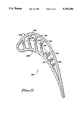
- FIG. 2 is an elevational cross-sectional view extending irregularly along the length of the core of a turbine blade constructed in accordance with the principles of the present invention, as taken along lines 2--2 of FIG. 3;
- FIG. 3 is a top plan cross-sectional view taken along lines 3--3 of FIG. 2;
- FIG. 4 is a front elevational cross-sectional view taken along lines 4--4 of FIG. 3;
- FIG. 5 is a view similar to FIG. 3 but showing a modified version of the present invention.
- a gas turbine engine denoted by the numeral 10 includes a hot gas carrying passage 12 having an axial turbine blade 14 extending radially from the center line of the rotating hub of a rotary turbine wheel 16.
- blade 14 extends in a generally axial direction from a leading edge 18 toward a trailing edge 20 relative to the motive gas flow passing thereby.
- the blade 14 is arcuately curved in a chord-wise direction extending along the central mean camber line from the center of the leading edge 18 to the trailing edge 20.
- the blade extends tangentially in a circumferential direction relative to rotation of wheel 16 and has a pressure side 22 spaced circumferentially from a suction side 24.
- the turbine blade extends radially from an inner or bottom platform 26 to a top platform 28.
- the bottom platform 26 may have a dovetail configuration 30 for intersecurement in a correspondingly configured dovetail groove in the hub of the turbine wheel 16 for intersecurement therewith.
- the top platform 28 includes a tip cap portion 32 surrounded by an upstanding squealer tip 34.
- blade 14 may be manufactured in a variety of manners, a preferred approach contemplates casting two blade halves 14P, 14S. As best illustrated in FIG. 3 the subsequent bond line for these two castings halves is represented by the line 36 and extends generally near the mean camber line of the blade 14. Alternately, the two blade halves 14P, 14S may be machined from stock. If cast from single crystal alloys, both halves 14P, 14S are grown by known seeding techniques to avoid high angled grain boundaries at the bond joint. Prior to bonding of the two blade halves, internal cooling passages, as needed, may be created by electrical discharge machining or by electrochemical machining.
- the two blade halves are then bonded together by conventional bonding techniques suitable for the superalloys normally utilized for gas turbine blades. After bonding, the final external airfoil shaping and the forming of dovetail 30 are accomplished through machining as needed.
- a plurality of tangential or circumferentially extending ribs 38, 40, 42, 46, 48, and 50 extend internally across the hollowed interior of blade 14 between the pressure side 22 and suction side 24.
- These ribs 38-50 define a plurality of span-wise extending internal cavities 52, 54, 56, 58, 60, 62, 64 and 66. These cavities 52-66 are spaced in a chord-wise direction from one another, being separated by the ribs 38-50, and a mid-chord located cavity 56 communicates with a cooling air supply passage 67 extending radially inwardly into the dovetail region of the blade for receiving cooling air flow from another part of the engine.
- the internal ribs have associated passages 39, 41P, 41S, 43P, 43S, 45, 47, 49 and 51, all of which facilitate delivery of the cooling air flow to the adjacent cavities in a generally chordwise direction along the blade 14.
- the smaller drilled passages 39, 41P, 41S, 43P, 43S, and 45 preferably are drilled through electrical discharge machining or electrochemical machining of the two separate halves 14P, 14S before bonding thereof.
- the blade 14 is configured with exhaust apertures 68, 70 and 72, only a portion of which are illustrated in the drawings, for the purpose of exhausting the cooling air flow from the interior cavities to the exterior of the blade on either the pressure side 22, the suction side 24, or at the trailing edge 20 thereof.
- midchord cavity 56, and/or other cavities may include one or more exhaust passages 74 extending through the tip cap 32. These exhaust apertures assure continuous flow of cooling air flow into, through, and out of the interior of the hollowed blade 14.
- a very important aspect of the present invention relates to the configuration of ribs 40, 42 and their associated passages 41P, 41S, 43P and 43S. More particularly, it will be noted in FIG. 3 that the internal ribs 38 and 40 do not extend across the interior of the blade 14 in a straight line.
- Each of the ribs 38 and 40 is comprised of a pair of segments, one associated with each of the casting halves 14P, 14S. The straight segments of rib 38 are angled to one another and joined at the bond line 36. Similarly, each of the segments making up rib 40 are straight or linear, but are angled to one another and are joined at the bond line. Thus, each of the ribs 38, 40 extend indirectly across the interior of the hollowed blade 14 between the pressure side and suction side.
- passages 41P, 41S associated with the nonlinear rib 40 are drilled at an angle therethrough rather readily prior to bonding of the casting halves 14P and 14S. More particularly, passages 41P are aligned such that cooling air flow issuing therefrom from cavity 56 is directed into the adjacent cavity 54 to impinge substantially at the corner formed between the next adjacent rib 38 and the internal surface of the pressure side 22 of the turbine blade. Because of the angulation of the segment of rib 40 which carries the passages 41P, these passages 41P are at a substantially right angle to the segment of the rib 40. As a net result, the cooling air flow impinges directly upon the above-mentioned corner. Thus the cooling airflow impinges directly upon substantial portions of both the internal surface of the pressure side 22 as well as upon the next adjacent rib 38.
- passages 41P and the associated rib 40 assure that the cooling air flow issuing into cavity 54 impinges upon a substantial portion of both the internal surface of the pressure side 22 as well as upon the next adjacent rib 38 This promotes very effective impingement cooling of both the pressure side 22 as well as rib 38. Because the passage 41P is extending almost perpendicularly through the associated segment of the internal rib 40, the diameter of passage 41P can be substantially large in comparison to the thickness of rib 40; yet the direction of cooling air flow issuing therethrough will still assure impingement adjacent the corner of the next adjacent rib to promote the impingement cooling upon both mentioned walls.
- the length-to-diameter ratio of the passage 41P may be significantly less than three, and impingement cooling will still occur upon both of the internal surface of pressure side 22 and the next adjacent rib 38.
- air flow through a passage in a wall will generally follow the direction of that passage so long as its length-to-diameter ratio is approximately three or higher. If the length-to-diameter ratio is less than three, the air flow through such a passage tends to be perpendicular to the plane of the wall through which the aperture or passage extends.
- the passage 41P may be of substantially large diameter in comparison to its length through the rib 40 so as to allow significant air flow therethrough, yet still assuring that the air flow is issuing toward the corner formed at the next adjacent rib. This is especially important for passages 41P because flow in the forward end of the blade must exhaust through apertures 68 into a relatively high pressure region external to blade 14. This means there is a lower pressure differential between cavity 56 and apertures 68 for forcing cooling flow through passages 41P. By allowing passage 41P to be relatively large, i.e. length-to-diameter ratio less than three, sufficient cooling air flow occurs therethrough even with the minimized pressure differential.
- passages 41S are drilled in a line such that cooling air flow passing therethrough from cavity 56 into cavity 54 is also directed toward the corner formed between the next adjacent rib 38 and the internal surface associated with suction side 24. By being directed towards this corner, impingement cooling occurs across a large portion of the internal surface associated with section side 24, as well as upon the next adjacent rib 38. Like cooling air flow through passage 41P, this resulting impingement cooling caused by the cooling air flow issuing through passage 41S maximizes the heat exchange effects and maximizes cooling of the turbine blade in a region wherein the blade 14 is exposed to higher temperatures.
- the configuration of the segment of rib 40 associated with the suction side casting 14S assures that the associated passage 41S has a significantly higher length-to-diameter ratio than the associated passage 41P. This, coupled with the angulation of passage 41S, assures that the fluid flow issuing from passage 41S into the adjacent cavity 54 is generally toward the corner between the next adjacent rib 38 and the internal surface of the suction side 24.
- the passages 41P and 41S comprise a column of passages extending spanwise or radially along the rib 40.
- the passages 41P, 41S can also be spaced and arranged to produce preferential cooling by controlling the volume of cooling air flow directed into different portions of the cavity 54.
- the more critical temperature zone of such a turbine blade 14 tends to be towards the central portion thereof in a spanwise direction, i.e. in a direction from the bottom platform 26 towards the top platform 28.
- each of the passages 41P and 41S are arranged in greater concentration in the midspan portion of the blade than in those portions more adjacent either the bottom platform 26 or the top platform 28.
- Impingement cooling directly upon the internal surfaces associated with pressure side 22 and suction side 24 within the cavity 54 is important as it promotes maximum cooling of the blade in these regions. Impingement cooling upon the next adjacent rib 38 is also important inasmuch as the cooled rib 38 now acts as a heat sink so that greater heat may be removed from the blade through conduction in to the internal rib 38. Additionally, this impingement cooling of rib 38 is important from a mechanical point of view inasmuch as the cooled rib 38 is better able to carry the blade loading.
- Passage 76 directs cooling air flow to impinge directly upon the tip cap 32 in an area adjacent the squealer cap 34 near the leading edge 18 of the blade. Such impingement cooling produces higher internal heat transfer coefficient, allowing additional cooling of the squealer cap adjacent the leading edge via conduction through the tip cap 32.
- the present invention thereby improves the internal heat transfer coefficients in comparison to relying merely upon convection heat transfer from the pressure side and suction side of the blades. Yet the present invention accomplishes this improved heat transfer with a relatively simplified internal cooling configuration in comparison to prior art. For example, prior art attempts to produce impingement cooling upon the internal surfaces associated with the pressure side and the suction side of a blade characteristically involved utilization of a double internal wall. When viewing internal ribs 38 and 40 it will be apparent that the internal geometry of the hollowed blade of the present invention is vastly simpler than characteristic of a majority of the prior art arrangements.
- Cooling air flow from the midspan cavity 56 in passing rearwardly towards the trailing edge 20 of the blade will ultimately exhaust through passages such as those illustrated at 70 and 72.
- exhausting cooling air flow passing through apertures 70 and 72 dump in to an external region of significantly lower pressure than normally encountered by aperture 68.
- the internal rib 42 may be linear in configuration extending in a straight line between the pressure side and suction side.
- the associated passages 43S, and 43P are of substantially smaller diameter than the passages 41P and 41S.
- passages 43S, and 43P may be of substantially smaller diameter and yet carry necessary cooling air flow as required by the blade. Because the diameter of passages 43P, 43S are significantly smaller, there length-to-diameter ratio can be on the order of approximately three to one.
- the passage 43P is aligned such that its axis is directed substantially towards the corner formed between the next adjacent rib 45 and the pressure side internal surface.
- the passage 43S is arranged such that fluid flow issuing therefrom is directed substantially at the corner formed between next adjacent rib 45 and the internal surface associated with suction side 24.
- impingement cooling again occurs on the internal surfaces of both the pressure side and suction side in the region of cavity 58, along with impingement cooling of the next adjacent rib 44.
- the rib 42 and its associated passages 43P, 43S are configured and arranged such that the cooling air flow passing therethrough does cause impingement cooling in the same manner as set forth above with respect to passages 41P and 41S.
- the present invention may be utilized in conjunction with other known heat exchange geometrical configurations.
- the internal supply cavity 56 may include a plurality of turbulators 78 associated with the internal surfaces on both the pressure side and suction side.
- the walls 46, 48 and 50 may comprise a series of tubulators 80 extending a short distance from the internal surfaces of the pressure side and suction side, and/or may include a plurality of pin fins 82 extending substantially across the tangential or circumferential width of the blade.
- Such heat exchange fins and tubulators are typical and well known within the art.
- FIG. 5 illustrates an alternative form of the invention wherein a turbine blade 140 includes three internal ribs 142, 144 and 146 each of which is of nonlinear configuration in the same manner as discussed above with respect to blade 40 of FIG. 3. Associated passages 143, 145 and 147 therewithin are configured and arranged as discussed previously such that cooling air flow passing therethrough issues directly toward the corners form between the next adjacent blade and the internal surface of both the pressure side and the suction side of the turbine blade 140.
- the bond line between the pair of casting halves 140P and 140S is offset further from the main camber line of the blade near the leading edge of the blade. While increasing complexity of the casting process, the blade of FIG.
- blade 140 includes a pair of ribs 148, 150 which are linear but which have associated passages 149, 151 therewithin which have a length-to-diameter ratio of approximately three or greater so that cooling air flow again impinges not only upon the internal surfaces of the pressure side and suction side, but also impinges upon the next adjacent internal rib.
- ribs 148, 150 which are linear but which have associated passages 149, 151 therewithin which have a length-to-diameter ratio of approximately three or greater so that cooling air flow again impinges not only upon the internal surfaces of the pressure side and suction side, but also impinges upon the next adjacent internal rib.
- Various other internal features, including the exhaust apertures are not illustrated in FIG. 5 for purposes of clarity.
- the present invention contemplates an improved internal geometry for a fluid foil such that internal heat transfer coefficients are dramatically increased. This allows operation of the fluid flow at a higher temperature, such as when operating as a turbine blade or vane, or alternately allows a reduced flow of cooling air to minimize parasitic power losses.
- the concepts of the present invention are readily adaptable to a heat exchange arrangement with a fluid foil which must be heated, rather than cooled. In such instance the heat exchange fluid delivered in to the hollowed interior of the fluid foil would be a heating fluid rather than a cooling fluid.
Abstract
Description
Claims (7)
Priority Applications (1)
| Application Number | Priority Date | Filing Date | Title |
|---|---|---|---|
| US07/794,756 US5246340A (en) | 1991-11-19 | 1991-11-19 | Internally cooled airfoil |
Applications Claiming Priority (1)
| Application Number | Priority Date | Filing Date | Title |
|---|---|---|---|
| US07/794,756 US5246340A (en) | 1991-11-19 | 1991-11-19 | Internally cooled airfoil |
Publications (1)
| Publication Number | Publication Date |
|---|---|
| US5246340A true US5246340A (en) | 1993-09-21 |
Family
ID=25163589
Family Applications (1)
| Application Number | Title | Priority Date | Filing Date |
|---|---|---|---|
| US07/794,756 Expired - Lifetime US5246340A (en) | 1991-11-19 | 1991-11-19 | Internally cooled airfoil |
Country Status (1)
| Country | Link |
|---|---|
| US (1) | US5246340A (en) |
Cited By (84)
| Publication number | Priority date | Publication date | Assignee | Title |
|---|---|---|---|---|
| US5387085A (en) * | 1994-01-07 | 1995-02-07 | General Electric Company | Turbine blade composite cooling circuit |
| US5472316A (en) * | 1994-09-19 | 1995-12-05 | General Electric Company | Enhanced cooling apparatus for gas turbine engine airfoils |
| US5503527A (en) * | 1994-12-19 | 1996-04-02 | General Electric Company | Turbine blade having tip slot |
| US5511946A (en) * | 1994-12-08 | 1996-04-30 | General Electric Company | Cooled airfoil tip corner |
| US5688104A (en) * | 1993-11-24 | 1997-11-18 | United Technologies Corporation | Airfoil having expanded wall portions to accommodate film cooling holes |
| US6036441A (en) * | 1998-11-16 | 2000-03-14 | General Electric Company | Series impingement cooled airfoil |
| EP1022434A2 (en) * | 1999-01-25 | 2000-07-26 | General Electric Company | Gas turbine blade cooling configuration |
| US6153889A (en) * | 1998-03-20 | 2000-11-28 | Rolls-Royce Plc | Method and an apparatus for inspecting articles |
| US6213714B1 (en) | 1999-06-29 | 2001-04-10 | Allison Advanced Development Company | Cooled airfoil |
| EP1197635A2 (en) * | 2000-10-12 | 2002-04-17 | Solar Turbines Incorporated | Gas turbine engine airfoil cooling |
| US6454526B1 (en) * | 2000-09-28 | 2002-09-24 | Siemens Westinghouse Power Corporation | Cooled turbine vane with endcaps |
| EP1314855A2 (en) * | 2001-11-21 | 2003-05-28 | ROLLS-ROYCE plc | Gas turbine engine aerofoil |
| EP1557528A2 (en) * | 2004-01-26 | 2005-07-27 | United Technologies Corporation | Hollow fan blade for gas turbine engine |
| EP1557529A2 (en) * | 2004-01-26 | 2005-07-27 | United Technologies Corporation | Hollow fan blade for gas turbine engine |
| US20050226726A1 (en) * | 2004-04-08 | 2005-10-13 | Ching-Pang Lee | Cascade impingement cooled airfoil |
| JP2005299637A (en) * | 2004-04-14 | 2005-10-27 | General Electric Co <Ge> | Method and device for reducing turbine blade temperature |
| US20060104813A1 (en) * | 2004-11-18 | 2006-05-18 | General Electric Company | Cooling system for an airfoil |
| EP1380724A3 (en) * | 2002-07-11 | 2006-11-02 | Mitsubishi Heavy Industries, Ltd. | Cooled turbine blade |
| US20060269408A1 (en) * | 2005-05-26 | 2006-11-30 | Siemens Westinghouse Power Corporation | Turbine airfoil trailing edge cooling system with segmented impingement ribs |
| EP1728970A2 (en) | 2005-05-31 | 2006-12-06 | United Technologies Corporation | Turbine blade cooling system |
| US20070036652A1 (en) * | 2005-08-15 | 2007-02-15 | United Technologies Corporation | Hollow fan blade for gas turbine engine |
| US20070128036A1 (en) * | 2005-12-05 | 2007-06-07 | Snecma | Turbine blade with cooling and with improved service life |
| US20070128034A1 (en) * | 2005-12-05 | 2007-06-07 | General Electric Company | Zigzag cooled turbine airfoil |
| US20070128042A1 (en) * | 2005-12-06 | 2007-06-07 | United Technologies Corporation | Hollow fan blade for gas turbine engine |
| US20070297917A1 (en) * | 2006-06-22 | 2007-12-27 | United Technologies Corporation | Leading edge cooling using chevron trip strips |
| US20070297916A1 (en) * | 2006-06-22 | 2007-12-27 | United Technologies Corporation | Leading edge cooling using wrapped staggered-chevron trip strips |
| US20080050244A1 (en) * | 2006-08-28 | 2008-02-28 | United Technologies Corporation | Turbine blade with split impingement rib |
| EP1895096A1 (en) * | 2006-09-04 | 2008-03-05 | Siemens Aktiengesellschaft | Cooled turbine rotor blade |
| GB2443638A (en) * | 2006-11-09 | 2008-05-14 | Rolls Royce Plc | An air-cooled component |
| CN101377132A (en) * | 2007-08-30 | 2009-03-04 | 通用电气公司 | Multi-part cast turbine engine component having an internal cooling channel and method of forming the same |
| US20090123292A1 (en) * | 2007-11-14 | 2009-05-14 | Siemens Power Generation, Inc. | Turbine Blade Tip Cooling System |
| US20090206203A1 (en) * | 2006-07-28 | 2009-08-20 | Tristan Crawford | Aircraft wing box and manufacture thereof |
| EP2107215A1 (en) | 2008-03-31 | 2009-10-07 | ALSTOM Technology Ltd | Gas turbine airfoil |
| US20090317234A1 (en) * | 2008-06-18 | 2009-12-24 | Jack Raul Zausner | Crossflow turbine airfoil |
| US20100054933A1 (en) * | 2008-09-04 | 2010-03-04 | James Allister W | Stationary turbine component with laminated skin |
| US7690892B1 (en) | 2006-11-16 | 2010-04-06 | Florida Turbine Technologies, Inc. | Turbine airfoil with multiple impingement cooling circuit |
| US20100329835A1 (en) * | 2009-06-26 | 2010-12-30 | United Technologies Corporation | Airfoil with hybrid drilled and cutback trailing edge |
| US7862299B1 (en) * | 2007-03-21 | 2011-01-04 | Florida Turbine Technologies, Inc. | Two piece hollow turbine blade with serpentine cooling circuits |
| US20110052413A1 (en) * | 2009-08-31 | 2011-03-03 | Okey Kwon | Cooled gas turbine engine airflow member |
| US20110059290A1 (en) * | 2009-09-08 | 2011-03-10 | Honeywell International Inc. | Bonded assemblies and methods for improving bond strength of a joint |
| US20110110772A1 (en) * | 2009-11-11 | 2011-05-12 | Arrell Douglas J | Turbine Engine Components with Near Surface Cooling Channels and Methods of Making the Same |
| US20110146075A1 (en) * | 2009-12-18 | 2011-06-23 | Brian Thomas Hazel | Methods for making a turbine blade |
| EP1944468A3 (en) * | 2007-01-11 | 2012-07-18 | Rolls-Royce plc | Gas turbine blade |
| CN102943693A (en) * | 2012-11-29 | 2013-02-27 | 哈尔滨汽轮机厂有限责任公司 | Efficient cooling turbine movable vane of gas turbine with low-heat and medium-heat values |
| CN102953766A (en) * | 2011-08-24 | 2013-03-06 | 通用电气公司 | Axially cooled airfoil |
| US20130142666A1 (en) * | 2011-12-06 | 2013-06-06 | Ching-Pang Lee | Turbine blade incorporating trailing edge cooling design |
| US20130280091A1 (en) * | 2012-04-24 | 2013-10-24 | Mark F. Zelesky | Gas turbine engine airfoil impingement cooling |
| EP2258925A3 (en) * | 2009-06-01 | 2013-12-11 | Rolls-Royce plc | Cooling arrangements |
| WO2014011289A3 (en) * | 2012-04-24 | 2014-03-27 | United Technologies Corporation | Airfoil having minimum distance ribs |
| JP2014134201A (en) * | 2013-01-09 | 2014-07-24 | General Electric Co <Ge> | Interior configuration for turbine rotor blade |
| KR101464988B1 (en) * | 2013-11-12 | 2014-11-26 | 연세대학교 산학협력단 | Gas Turbine Blade Having an Internal Cooling Passage Structure for Improving Cooling Performance |
| US20150004001A1 (en) * | 2012-03-22 | 2015-01-01 | Alstom Technology Ltd | Turbine blade |
| US9039371B2 (en) | 2013-10-31 | 2015-05-26 | Siemens Aktiengesellschaft | Trailing edge cooling using angled impingement on surface enhanced with cast chevron arrangements |
| US20160003053A1 (en) * | 2013-01-15 | 2016-01-07 | United Technologies Corporation | Gas turbine engine component having transversely angled impingement ribs |
| US20160230565A1 (en) * | 2015-02-10 | 2016-08-11 | United Technologies Corporation | Flared crossovers for airfoils |
| US20160265363A1 (en) * | 2013-11-08 | 2016-09-15 | United Technologies Corporation | Bonded multi-piece gas turbine engine component |
| US20170350256A1 (en) * | 2016-06-06 | 2017-12-07 | General Electric Company | Turbine component and methods of making and cooling a turbine component |
| US9874110B2 (en) | 2013-03-07 | 2018-01-23 | Rolls-Royce North American Technologies Inc. | Cooled gas turbine engine component |
| US9879601B2 (en) | 2013-03-05 | 2018-01-30 | Rolls-Royce North American Technologies Inc. | Gas turbine engine component arrangement |
| JP2018506678A (en) * | 2015-01-22 | 2018-03-08 | シーメンス エナジー インコーポレイテッド | Turbine blade cooling system with a squealer tip cooling channel extending in the chordal direction |
| CN108223018A (en) * | 2017-12-28 | 2018-06-29 | 中国航发四川燃气涡轮研究院 | A kind of open-celled structure for reducing the hollow moving turbine blade blade impact around-the-hole stress of aero-engine |
| US20180306038A1 (en) * | 2015-05-12 | 2018-10-25 | United Technologies Corporation | Airfoil impingement cavity |
| US10145246B2 (en) | 2014-09-04 | 2018-12-04 | United Technologies Corporation | Staggered crossovers for airfoils |
| US20190048727A1 (en) * | 2013-09-24 | 2019-02-14 | United Technologies Corporation | Bonded multi-piece gas turbine engine component |
| US20190101008A1 (en) * | 2017-10-03 | 2019-04-04 | United Technologies Corporation | Airfoil having internal hybrid cooling cavities |
| US10370976B2 (en) | 2017-08-17 | 2019-08-06 | United Technologies Corporation | Directional cooling arrangement for airfoils |
| US10472973B2 (en) * | 2016-06-06 | 2019-11-12 | General Electric Company | Turbine component and methods of making and cooling a turbine component |
| US20200024966A1 (en) * | 2018-07-19 | 2020-01-23 | General Electric Company | Airfoil with Tunable Cooling Configuration |
| US10570748B2 (en) | 2018-01-10 | 2020-02-25 | United Technologies Corporation | Impingement cooling arrangement for airfoils |
| US10577944B2 (en) | 2017-08-03 | 2020-03-03 | General Electric Company | Engine component with hollow turbulators |
| US10590778B2 (en) | 2017-08-03 | 2020-03-17 | General Electric Company | Engine component with non-uniform chevron pins |
| US10626733B2 (en) | 2017-10-03 | 2020-04-21 | United Technologies Corporation | Airfoil having internal hybrid cooling cavities |
| US10626731B2 (en) * | 2017-07-31 | 2020-04-21 | Rolls-Royce Corporation | Airfoil leading edge cooling channels |
| US10626734B2 (en) | 2017-10-03 | 2020-04-21 | United Technologies Corporation | Airfoil having internal hybrid cooling cavities |
| US10633980B2 (en) | 2017-10-03 | 2020-04-28 | United Technologies Coproration | Airfoil having internal hybrid cooling cavities |
| US10704397B2 (en) | 2015-04-03 | 2020-07-07 | Siemens Aktiengesellschaft | Turbine blade trailing edge with low flow framing channel |
| US10844732B2 (en) | 2017-12-14 | 2020-11-24 | Rolls-Royce Plc | Aerofoil and method of manufacture |
| US10968754B2 (en) | 2017-12-14 | 2021-04-06 | Rolls-Royce Plc | Aerofoil |
| US11111857B2 (en) | 2019-07-18 | 2021-09-07 | Raytheon Technologies Corporation | Hourglass airfoil cooling configuration |
| US20210324741A1 (en) * | 2020-04-16 | 2021-10-21 | Raytheon Technologies Corporation | Airfoil with y-shaped rib |
| US11203940B2 (en) | 2016-11-15 | 2021-12-21 | Rolls-Royce Corporation | Dual-wall airfoil with leading edge cooling slot |
| US11401818B2 (en) | 2018-08-06 | 2022-08-02 | General Electric Company | Turbomachine cooling trench |
| EP4105442A1 (en) * | 2021-06-17 | 2022-12-21 | Raytheon Technologies Corporation | Improved cooling schemes for airfoils for gas turbine engines |
| US11585224B2 (en) | 2020-08-07 | 2023-02-21 | General Electric Company | Gas turbine engines and methods associated therewith |
Citations (13)
| Publication number | Priority date | Publication date | Assignee | Title |
|---|---|---|---|---|
| US2248221A (en) * | 1937-03-20 | 1941-07-08 | Dornier Werke Gmbh | Propeller blade |
| US2659444A (en) * | 1949-06-21 | 1953-11-17 | Autogiro Co Of America | Molded aircraft sustaining rotor blade |
| US3237850A (en) * | 1964-08-24 | 1966-03-01 | Borg Warner | Axial flow fan with boundary layer control |
| US3628226A (en) * | 1970-03-16 | 1971-12-21 | Aerojet General Co | Method of making hollow compressor blades |
| US3732031A (en) * | 1970-06-17 | 1973-05-08 | Gen Motors Corp | Cooled airfoil |
| US3736638A (en) * | 1971-04-07 | 1973-06-05 | United Aircraft Corp | Method for bonding opposed parts of a hollow article together |
| US4056332A (en) * | 1975-05-16 | 1977-11-01 | Bbc Brown Boveri & Company Limited | Cooled turbine blade |
| US4089456A (en) * | 1977-06-28 | 1978-05-16 | United Technologies Corporation | Controlled-pressure diffusion bonding and fixture therefor |
| US4221539A (en) * | 1977-04-20 | 1980-09-09 | The Garrett Corporation | Laminated airfoil and method for turbomachinery |
| US4601638A (en) * | 1984-12-21 | 1986-07-22 | United Technologies Corporation | Airfoil trailing edge cooling arrangement |
| US4815939A (en) * | 1986-11-03 | 1989-03-28 | Airfoil Textron Inc. | Twisted hollow airfoil with non-twisted internal support ribs |
| US4827587A (en) * | 1988-01-25 | 1989-05-09 | United Technologies Corporation | Method of fabricating an air cooled turbine blade |
| US5083371A (en) * | 1990-09-14 | 1992-01-28 | United Technologies Corporation | Hollow metal article fabrication |
-
1991
- 1991-11-19 US US07/794,756 patent/US5246340A/en not_active Expired - Lifetime
Patent Citations (13)
| Publication number | Priority date | Publication date | Assignee | Title |
|---|---|---|---|---|
| US2248221A (en) * | 1937-03-20 | 1941-07-08 | Dornier Werke Gmbh | Propeller blade |
| US2659444A (en) * | 1949-06-21 | 1953-11-17 | Autogiro Co Of America | Molded aircraft sustaining rotor blade |
| US3237850A (en) * | 1964-08-24 | 1966-03-01 | Borg Warner | Axial flow fan with boundary layer control |
| US3628226A (en) * | 1970-03-16 | 1971-12-21 | Aerojet General Co | Method of making hollow compressor blades |
| US3732031A (en) * | 1970-06-17 | 1973-05-08 | Gen Motors Corp | Cooled airfoil |
| US3736638A (en) * | 1971-04-07 | 1973-06-05 | United Aircraft Corp | Method for bonding opposed parts of a hollow article together |
| US4056332A (en) * | 1975-05-16 | 1977-11-01 | Bbc Brown Boveri & Company Limited | Cooled turbine blade |
| US4221539A (en) * | 1977-04-20 | 1980-09-09 | The Garrett Corporation | Laminated airfoil and method for turbomachinery |
| US4089456A (en) * | 1977-06-28 | 1978-05-16 | United Technologies Corporation | Controlled-pressure diffusion bonding and fixture therefor |
| US4601638A (en) * | 1984-12-21 | 1986-07-22 | United Technologies Corporation | Airfoil trailing edge cooling arrangement |
| US4815939A (en) * | 1986-11-03 | 1989-03-28 | Airfoil Textron Inc. | Twisted hollow airfoil with non-twisted internal support ribs |
| US4827587A (en) * | 1988-01-25 | 1989-05-09 | United Technologies Corporation | Method of fabricating an air cooled turbine blade |
| US5083371A (en) * | 1990-09-14 | 1992-01-28 | United Technologies Corporation | Hollow metal article fabrication |
Cited By (148)
| Publication number | Priority date | Publication date | Assignee | Title |
|---|---|---|---|---|
| US5688104A (en) * | 1993-11-24 | 1997-11-18 | United Technologies Corporation | Airfoil having expanded wall portions to accommodate film cooling holes |
| US5387085A (en) * | 1994-01-07 | 1995-02-07 | General Electric Company | Turbine blade composite cooling circuit |
| US5472316A (en) * | 1994-09-19 | 1995-12-05 | General Electric Company | Enhanced cooling apparatus for gas turbine engine airfoils |
| US5511946A (en) * | 1994-12-08 | 1996-04-30 | General Electric Company | Cooled airfoil tip corner |
| US5503527A (en) * | 1994-12-19 | 1996-04-02 | General Electric Company | Turbine blade having tip slot |
| US6153889A (en) * | 1998-03-20 | 2000-11-28 | Rolls-Royce Plc | Method and an apparatus for inspecting articles |
| US6036441A (en) * | 1998-11-16 | 2000-03-14 | General Electric Company | Series impingement cooled airfoil |
| EP1022434A2 (en) * | 1999-01-25 | 2000-07-26 | General Electric Company | Gas turbine blade cooling configuration |
| EP1022434A3 (en) * | 1999-01-25 | 2001-11-14 | General Electric Company | Gas turbine blade cooling configuration |
| US6213714B1 (en) | 1999-06-29 | 2001-04-10 | Allison Advanced Development Company | Cooled airfoil |
| US6454526B1 (en) * | 2000-09-28 | 2002-09-24 | Siemens Westinghouse Power Corporation | Cooled turbine vane with endcaps |
| US6431832B1 (en) * | 2000-10-12 | 2002-08-13 | Solar Turbines Incorporated | Gas turbine engine airfoils with improved cooling |
| EP1197635A2 (en) * | 2000-10-12 | 2002-04-17 | Solar Turbines Incorporated | Gas turbine engine airfoil cooling |
| EP1197635A3 (en) * | 2000-10-12 | 2003-05-28 | Solar Turbines Incorporated | Gas turbine engine airfoil cooling |
| EP1314855A2 (en) * | 2001-11-21 | 2003-05-28 | ROLLS-ROYCE plc | Gas turbine engine aerofoil |
| EP1314855A3 (en) * | 2001-11-21 | 2004-09-01 | ROLLS-ROYCE plc | Gas turbine engine aerofoil |
| US6837683B2 (en) | 2001-11-21 | 2005-01-04 | Rolls-Royce Plc | Gas turbine engine aerofoil |
| EP1380724A3 (en) * | 2002-07-11 | 2006-11-02 | Mitsubishi Heavy Industries, Ltd. | Cooled turbine blade |
| EP1557528A2 (en) * | 2004-01-26 | 2005-07-27 | United Technologies Corporation | Hollow fan blade for gas turbine engine |
| EP1557529A2 (en) * | 2004-01-26 | 2005-07-27 | United Technologies Corporation | Hollow fan blade for gas turbine engine |
| EP1557528A3 (en) * | 2004-01-26 | 2006-01-18 | United Technologies Corporation | Hollow fan blade for gas turbine engine |
| EP1557529A3 (en) * | 2004-01-26 | 2006-01-18 | United Technologies Corporation | Hollow fan blade for gas turbine engine |
| US20050226726A1 (en) * | 2004-04-08 | 2005-10-13 | Ching-Pang Lee | Cascade impingement cooled airfoil |
| US7097426B2 (en) * | 2004-04-08 | 2006-08-29 | General Electric Company | Cascade impingement cooled airfoil |
| US7217092B2 (en) * | 2004-04-14 | 2007-05-15 | General Electric Company | Method and apparatus for reducing turbine blade temperatures |
| US20070059172A1 (en) * | 2004-04-14 | 2007-03-15 | Ching-Pang Lee | Method and apparatus for reducing turbine blade temperatures |
| JP2005299637A (en) * | 2004-04-14 | 2005-10-27 | General Electric Co <Ge> | Method and device for reducing turbine blade temperature |
| EP1659263A2 (en) | 2004-11-18 | 2006-05-24 | General Electric Company | Cooling system for a gas turbine airfoil |
| US20060104813A1 (en) * | 2004-11-18 | 2006-05-18 | General Electric Company | Cooling system for an airfoil |
| JP2006144786A (en) * | 2004-11-18 | 2006-06-08 | General Electric Co <Ge> | Cooling system for airfoil section |
| EP1659263A3 (en) * | 2004-11-18 | 2009-12-16 | General Electric Company | Cooling system for a gas turbine airfoil |
| US7168921B2 (en) * | 2004-11-18 | 2007-01-30 | General Electric Company | Cooling system for an airfoil |
| US20060269408A1 (en) * | 2005-05-26 | 2006-11-30 | Siemens Westinghouse Power Corporation | Turbine airfoil trailing edge cooling system with segmented impingement ribs |
| US7270515B2 (en) | 2005-05-26 | 2007-09-18 | Siemens Power Generation, Inc. | Turbine airfoil trailing edge cooling system with segmented impingement ribs |
| EP1728970A2 (en) | 2005-05-31 | 2006-12-06 | United Technologies Corporation | Turbine blade cooling system |
| EP1728970A3 (en) * | 2005-05-31 | 2009-12-09 | United Technologies Corporation | Turbine blade cooling system |
| US20070036652A1 (en) * | 2005-08-15 | 2007-02-15 | United Technologies Corporation | Hollow fan blade for gas turbine engine |
| US7458780B2 (en) | 2005-08-15 | 2008-12-02 | United Technologies Corporation | Hollow fan blade for gas turbine engine |
| US20070128034A1 (en) * | 2005-12-05 | 2007-06-07 | General Electric Company | Zigzag cooled turbine airfoil |
| US7293961B2 (en) | 2005-12-05 | 2007-11-13 | General Electric Company | Zigzag cooled turbine airfoil |
| US20070128036A1 (en) * | 2005-12-05 | 2007-06-07 | Snecma | Turbine blade with cooling and with improved service life |
| US7670112B2 (en) * | 2005-12-05 | 2010-03-02 | Snecma | Turbine blade with cooling and with improved service life |
| US20070128042A1 (en) * | 2005-12-06 | 2007-06-07 | United Technologies Corporation | Hollow fan blade for gas turbine engine |
| US7993105B2 (en) | 2005-12-06 | 2011-08-09 | United Technologies Corporation | Hollow fan blade for gas turbine engine |
| US20070297916A1 (en) * | 2006-06-22 | 2007-12-27 | United Technologies Corporation | Leading edge cooling using wrapped staggered-chevron trip strips |
| US8690538B2 (en) * | 2006-06-22 | 2014-04-08 | United Technologies Corporation | Leading edge cooling using chevron trip strips |
| US20070297917A1 (en) * | 2006-06-22 | 2007-12-27 | United Technologies Corporation | Leading edge cooling using chevron trip strips |
| US20090206203A1 (en) * | 2006-07-28 | 2009-08-20 | Tristan Crawford | Aircraft wing box and manufacture thereof |
| US8172179B2 (en) * | 2006-07-28 | 2012-05-08 | Airbus Operations Limited | Aircraft wing box and manufacture thereof |
| US7713027B2 (en) * | 2006-08-28 | 2010-05-11 | United Technologies Corporation | Turbine blade with split impingement rib |
| US20080050244A1 (en) * | 2006-08-28 | 2008-02-28 | United Technologies Corporation | Turbine blade with split impingement rib |
| JP2010502872A (en) * | 2006-09-04 | 2010-01-28 | シーメンス アクチエンゲゼルシヤフト | Cooled turbine blade |
| WO2008028702A1 (en) * | 2006-09-04 | 2008-03-13 | Siemens Aktiengesellschaft | Cooled turbine rotor blade |
| EP1895096A1 (en) * | 2006-09-04 | 2008-03-05 | Siemens Aktiengesellschaft | Cooled turbine rotor blade |
| US20090252615A1 (en) * | 2006-09-04 | 2009-10-08 | Gross Heinz-Juergen | Cooled Turbine Rotor Blade |
| GB2443638B (en) * | 2006-11-09 | 2008-11-26 | Rolls Royce Plc | An air-cooled aerofoil |
| US20080112816A1 (en) * | 2006-11-09 | 2008-05-15 | Rolls-Royce Plc | Air-cooled component |
| GB2443638A (en) * | 2006-11-09 | 2008-05-14 | Rolls Royce Plc | An air-cooled component |
| US7976277B2 (en) | 2006-11-09 | 2011-07-12 | Rolls-Royce, Plc | Air-cooled component |
| US7690892B1 (en) | 2006-11-16 | 2010-04-06 | Florida Turbine Technologies, Inc. | Turbine airfoil with multiple impingement cooling circuit |
| US8297925B2 (en) | 2007-01-11 | 2012-10-30 | Rolls-Royce Plc | Aerofoil configuration |
| EP1944468A3 (en) * | 2007-01-11 | 2012-07-18 | Rolls-Royce plc | Gas turbine blade |
| US7862299B1 (en) * | 2007-03-21 | 2011-01-04 | Florida Turbine Technologies, Inc. | Two piece hollow turbine blade with serpentine cooling circuits |
| US20090060714A1 (en) * | 2007-08-30 | 2009-03-05 | General Electric Company | Multi-part cast turbine engine component having an internal cooling channel and method of forming a multi-part cast turbine engine component |
| CN101377132A (en) * | 2007-08-30 | 2009-03-04 | 通用电气公司 | Multi-part cast turbine engine component having an internal cooling channel and method of forming the same |
| US20090123292A1 (en) * | 2007-11-14 | 2009-05-14 | Siemens Power Generation, Inc. | Turbine Blade Tip Cooling System |
| US7934906B2 (en) * | 2007-11-14 | 2011-05-03 | Siemens Energy, Inc. | Turbine blade tip cooling system |
| US8231349B2 (en) | 2008-03-31 | 2012-07-31 | Alstom Technology Ltd. | Gas turbine airfoil |
| EP2107215A1 (en) | 2008-03-31 | 2009-10-07 | ALSTOM Technology Ltd | Gas turbine airfoil |
| US20100254824A1 (en) * | 2008-03-31 | 2010-10-07 | Shailendra Naik | Gas turbine airfoil |
| US20090317234A1 (en) * | 2008-06-18 | 2009-12-24 | Jack Raul Zausner | Crossflow turbine airfoil |
| US8210814B2 (en) | 2008-06-18 | 2012-07-03 | General Electric Company | Crossflow turbine airfoil |
| US20100054933A1 (en) * | 2008-09-04 | 2010-03-04 | James Allister W | Stationary turbine component with laminated skin |
| US8241001B2 (en) | 2008-09-04 | 2012-08-14 | Siemens Energy, Inc. | Stationary turbine component with laminated skin |
| EP2258925A3 (en) * | 2009-06-01 | 2013-12-11 | Rolls-Royce plc | Cooling arrangements |
| EP2267276A3 (en) * | 2009-06-26 | 2014-05-21 | United Technologies Corporation | Airfoil with hybrid drilled and cutback trailing edge |
| US20100329835A1 (en) * | 2009-06-26 | 2010-12-30 | United Technologies Corporation | Airfoil with hybrid drilled and cutback trailing edge |
| US9422816B2 (en) | 2009-06-26 | 2016-08-23 | United Technologies Corporation | Airfoil with hybrid drilled and cutback trailing edge |
| US20110052413A1 (en) * | 2009-08-31 | 2011-03-03 | Okey Kwon | Cooled gas turbine engine airflow member |
| US8342797B2 (en) | 2009-08-31 | 2013-01-01 | Rolls-Royce North American Technologies Inc. | Cooled gas turbine engine airflow member |
| US20110059290A1 (en) * | 2009-09-08 | 2011-03-10 | Honeywell International Inc. | Bonded assemblies and methods for improving bond strength of a joint |
| US20110110772A1 (en) * | 2009-11-11 | 2011-05-12 | Arrell Douglas J | Turbine Engine Components with Near Surface Cooling Channels and Methods of Making the Same |
| US20110146075A1 (en) * | 2009-12-18 | 2011-06-23 | Brian Thomas Hazel | Methods for making a turbine blade |
| CN102953766A (en) * | 2011-08-24 | 2013-03-06 | 通用电气公司 | Axially cooled airfoil |
| US9004866B2 (en) * | 2011-12-06 | 2015-04-14 | Siemens Aktiengesellschaft | Turbine blade incorporating trailing edge cooling design |
| US20130142666A1 (en) * | 2011-12-06 | 2013-06-06 | Ching-Pang Lee | Turbine blade incorporating trailing edge cooling design |
| US9932836B2 (en) * | 2012-03-22 | 2018-04-03 | Ansaldo Energia Ip Uk Limited | Turbine blade |
| US20150004001A1 (en) * | 2012-03-22 | 2015-01-01 | Alstom Technology Ltd | Turbine blade |
| EP2828484B1 (en) * | 2012-03-22 | 2019-05-08 | Ansaldo Energia IP UK Limited | Turbine blade |
| WO2014011289A3 (en) * | 2012-04-24 | 2014-03-27 | United Technologies Corporation | Airfoil having minimum distance ribs |
| US20130280091A1 (en) * | 2012-04-24 | 2013-10-24 | Mark F. Zelesky | Gas turbine engine airfoil impingement cooling |
| US10500633B2 (en) | 2012-04-24 | 2019-12-10 | United Technologies Corporation | Gas turbine engine airfoil impingement cooling |
| US9296039B2 (en) * | 2012-04-24 | 2016-03-29 | United Technologies Corporation | Gas turbine engine airfoil impingement cooling |
| US9404369B2 (en) | 2012-04-24 | 2016-08-02 | United Technologies Corporation | Airfoil having minimum distance ribs |
| CN102943693A (en) * | 2012-11-29 | 2013-02-27 | 哈尔滨汽轮机厂有限责任公司 | Efficient cooling turbine movable vane of gas turbine with low-heat and medium-heat values |
| JP2014134201A (en) * | 2013-01-09 | 2014-07-24 | General Electric Co <Ge> | Interior configuration for turbine rotor blade |
| US20160003053A1 (en) * | 2013-01-15 | 2016-01-07 | United Technologies Corporation | Gas turbine engine component having transversely angled impingement ribs |
| US9879601B2 (en) | 2013-03-05 | 2018-01-30 | Rolls-Royce North American Technologies Inc. | Gas turbine engine component arrangement |
| US9874110B2 (en) | 2013-03-07 | 2018-01-23 | Rolls-Royce North American Technologies Inc. | Cooled gas turbine engine component |
| US20190048727A1 (en) * | 2013-09-24 | 2019-02-14 | United Technologies Corporation | Bonded multi-piece gas turbine engine component |
| US9039371B2 (en) | 2013-10-31 | 2015-05-26 | Siemens Aktiengesellschaft | Trailing edge cooling using angled impingement on surface enhanced with cast chevron arrangements |
| EP3080401B1 (en) * | 2013-11-08 | 2020-10-14 | United Technologies Corporation | Bonded multi-piece gas turbine engine component |
| US20160265363A1 (en) * | 2013-11-08 | 2016-09-15 | United Technologies Corporation | Bonded multi-piece gas turbine engine component |
| US10458249B2 (en) * | 2013-11-08 | 2019-10-29 | United Technologies Corporation | Bonded multi-piece gas turbine engine component |
| KR101464988B1 (en) * | 2013-11-12 | 2014-11-26 | 연세대학교 산학협력단 | Gas Turbine Blade Having an Internal Cooling Passage Structure for Improving Cooling Performance |
| US10145246B2 (en) | 2014-09-04 | 2018-12-04 | United Technologies Corporation | Staggered crossovers for airfoils |
| JP2018506678A (en) * | 2015-01-22 | 2018-03-08 | シーメンス エナジー インコーポレイテッド | Turbine blade cooling system with a squealer tip cooling channel extending in the chordal direction |
| EP3056672A1 (en) * | 2015-02-10 | 2016-08-17 | United Technologies Corporation | Inclined crossover passages for airfoils |
| US10190420B2 (en) * | 2015-02-10 | 2019-01-29 | United Technologies Corporation | Flared crossovers for airfoils |
| EP3342982A1 (en) * | 2015-02-10 | 2018-07-04 | United Technologies Corporation | Inclined crossover passages for internal airfoil cavities |
| US20160230565A1 (en) * | 2015-02-10 | 2016-08-11 | United Technologies Corporation | Flared crossovers for airfoils |
| US10704397B2 (en) | 2015-04-03 | 2020-07-07 | Siemens Aktiengesellschaft | Turbine blade trailing edge with low flow framing channel |
| US20180306038A1 (en) * | 2015-05-12 | 2018-10-25 | United Technologies Corporation | Airfoil impingement cavity |
| US11319816B2 (en) | 2016-06-06 | 2022-05-03 | General Electric Company | Turbine component and methods of making and cooling a turbine component |
| US11333024B2 (en) * | 2016-06-06 | 2022-05-17 | General Electric Company | Turbine component and methods of making and cooling a turbine component |
| US20170350256A1 (en) * | 2016-06-06 | 2017-12-07 | General Electric Company | Turbine component and methods of making and cooling a turbine component |
| US10472973B2 (en) * | 2016-06-06 | 2019-11-12 | General Electric Company | Turbine component and methods of making and cooling a turbine component |
| US10590776B2 (en) * | 2016-06-06 | 2020-03-17 | General Electric Company | Turbine component and methods of making and cooling a turbine component |
| US11203940B2 (en) | 2016-11-15 | 2021-12-21 | Rolls-Royce Corporation | Dual-wall airfoil with leading edge cooling slot |
| US10626731B2 (en) * | 2017-07-31 | 2020-04-21 | Rolls-Royce Corporation | Airfoil leading edge cooling channels |
| US10590778B2 (en) | 2017-08-03 | 2020-03-17 | General Electric Company | Engine component with non-uniform chevron pins |
| US10577944B2 (en) | 2017-08-03 | 2020-03-03 | General Electric Company | Engine component with hollow turbulators |
| US10633978B2 (en) | 2017-08-17 | 2020-04-28 | United Technologies Corporation | Directional cooling arrangement for airfoils |
| US10370976B2 (en) | 2017-08-17 | 2019-08-06 | United Technologies Corporation | Directional cooling arrangement for airfoils |
| US10704398B2 (en) * | 2017-10-03 | 2020-07-07 | Raytheon Technologies Corporation | Airfoil having internal hybrid cooling cavities |
| US10626734B2 (en) | 2017-10-03 | 2020-04-21 | United Technologies Corporation | Airfoil having internal hybrid cooling cavities |
| US10633980B2 (en) | 2017-10-03 | 2020-04-28 | United Technologies Coproration | Airfoil having internal hybrid cooling cavities |
| US11649731B2 (en) | 2017-10-03 | 2023-05-16 | Raytheon Technologies Corporation | Airfoil having internal hybrid cooling cavities |
| US10626733B2 (en) | 2017-10-03 | 2020-04-21 | United Technologies Corporation | Airfoil having internal hybrid cooling cavities |
| US20190101008A1 (en) * | 2017-10-03 | 2019-04-04 | United Technologies Corporation | Airfoil having internal hybrid cooling cavities |
| US10844732B2 (en) | 2017-12-14 | 2020-11-24 | Rolls-Royce Plc | Aerofoil and method of manufacture |
| US10968754B2 (en) | 2017-12-14 | 2021-04-06 | Rolls-Royce Plc | Aerofoil |
| CN108223018A (en) * | 2017-12-28 | 2018-06-29 | 中国航发四川燃气涡轮研究院 | A kind of open-celled structure for reducing the hollow moving turbine blade blade impact around-the-hole stress of aero-engine |
| US10570748B2 (en) | 2018-01-10 | 2020-02-25 | United Technologies Corporation | Impingement cooling arrangement for airfoils |
| US11255197B2 (en) | 2018-01-10 | 2022-02-22 | Raytheon Technologies Corporation | Impingement cooling arrangement for airfoils |
| US20200024966A1 (en) * | 2018-07-19 | 2020-01-23 | General Electric Company | Airfoil with Tunable Cooling Configuration |
| US10837293B2 (en) * | 2018-07-19 | 2020-11-17 | General Electric Company | Airfoil with tunable cooling configuration |
| CN114607471A (en) * | 2018-07-19 | 2022-06-10 | 通用电气公司 | Airfoil with adjustable cooling configuration |
| CN110735665A (en) * | 2018-07-19 | 2020-01-31 | 通用电气公司 | Airfoil with adjustable cooling configuration |
| US11401818B2 (en) | 2018-08-06 | 2022-08-02 | General Electric Company | Turbomachine cooling trench |
| US11879356B2 (en) | 2018-08-06 | 2024-01-23 | General Electric Company | Turbomachine cooling trench |
| US11111857B2 (en) | 2019-07-18 | 2021-09-07 | Raytheon Technologies Corporation | Hourglass airfoil cooling configuration |
| US11624322B2 (en) | 2019-07-18 | 2023-04-11 | Raytheon Technologies Corporation | Hourglass airfoil cooling configuration |
| US11220912B2 (en) * | 2020-04-16 | 2022-01-11 | Raytheon Technologies Corporation | Airfoil with y-shaped rib |
| US20210324741A1 (en) * | 2020-04-16 | 2021-10-21 | Raytheon Technologies Corporation | Airfoil with y-shaped rib |
| US11585224B2 (en) | 2020-08-07 | 2023-02-21 | General Electric Company | Gas turbine engines and methods associated therewith |
| EP4105442A1 (en) * | 2021-06-17 | 2022-12-21 | Raytheon Technologies Corporation | Improved cooling schemes for airfoils for gas turbine engines |
| US11629602B2 (en) | 2021-06-17 | 2023-04-18 | Raytheon Technologies Corporation | Cooling schemes for airfoils for gas turbine engines |
Similar Documents
| Publication | Publication Date | Title |
|---|---|---|
| US5246340A (en) | Internally cooled airfoil | |
| US5348446A (en) | Bimetallic turbine airfoil | |
| US5486093A (en) | Leading edge cooling of turbine airfoils | |
| US3810711A (en) | Cooled turbine blade and its manufacture | |
| JP4607302B2 (en) | Cooling circuit and method for cooling a gas turbine bucket | |
| US5927946A (en) | Turbine blade having recuperative trailing edge tip cooling | |
| US5660524A (en) | Airfoil blade having a serpentine cooling circuit and impingement cooling | |
| US3849025A (en) | Serpentine cooling channel construction for open-circuit liquid cooled turbine buckets | |
| US6955522B2 (en) | Method and apparatus for cooling an airfoil | |
| US4604031A (en) | Hollow fluid cooled turbine blades | |
| US4650399A (en) | Rotor blade for a rotary machine | |
| US6290463B1 (en) | Slotted impingement cooling of airfoil leading edge | |
| US6554571B1 (en) | Curved turbulator configuration for airfoils and method and electrode for machining the configuration | |
| US3560107A (en) | Cooled airfoil | |
| US4501053A (en) | Method of making rotor blade for a rotary machine | |
| US4203706A (en) | Radial wafer airfoil construction | |
| EP1600604B1 (en) | Cooler rotor blade and method for cooling a rotor blade | |
| US3635587A (en) | Blade cooling liner | |
| US7824150B1 (en) | Multiple piece turbine airfoil | |
| US4738587A (en) | Cooled highly twisted airfoil for a gas turbine engine | |
| US8186953B1 (en) | Multiple piece turbine blade | |
| JPH08503530A (en) | Coolable airfoil and core for casting the airfoil | |
| US8382439B1 (en) | Process of forming a high temperature turbine rotor blade | |
| US6004100A (en) | Trailing edge cooling apparatus for a gas turbine airfoil | |
| JPH03194101A (en) | Gas turbine cooling moving blade |
Legal Events
| Date | Code | Title | Description |
|---|---|---|---|
| AS | Assignment |
Owner name: ALLIED-SIGNAL INC.,, DELAWARE Free format text: ASSIGNMENT OF ASSIGNORS INTEREST.;ASSIGNORS:WINSTANLEY, DAVID K.;PHILLIPS, JOHN K.;REEL/FRAME:005937/0995 Effective date: 19911118 |
|
| STCF | Information on status: patent grant |
Free format text: PATENTED CASE |
|
| AS | Assignment |
Owner name: ALLIEDSIGNAL INC., NEW JERSEY Free format text: CHANGE OF NAME;ASSIGNOR:ALLIED-SIGNAL INC.;REEL/FRAME:006704/0091 Effective date: 19930426 |
|
| FEPP | Fee payment procedure |
Free format text: PAYOR NUMBER ASSIGNED (ORIGINAL EVENT CODE: ASPN); ENTITY STATUS OF PATENT OWNER: LARGE ENTITY |
|
| FPAY | Fee payment |
Year of fee payment: 4 |
|
| FPAY | Fee payment |
Year of fee payment: 8 |
|
| FPAY | Fee payment |
Year of fee payment: 12 |